EP3574973A1 - Dispositif filtrant - Google Patents
Dispositif filtrant Download PDFInfo
- Publication number
- EP3574973A1 EP3574973A1 EP19162171.3A EP19162171A EP3574973A1 EP 3574973 A1 EP3574973 A1 EP 3574973A1 EP 19162171 A EP19162171 A EP 19162171A EP 3574973 A1 EP3574973 A1 EP 3574973A1
- Authority
- EP
- European Patent Office
- Prior art keywords
- openings
- group
- filter
- arrangement according
- tube
- Prior art date
- Legal status (The legal status is an assumption and is not a legal conclusion. Google has not performed a legal analysis and makes no representation as to the accuracy of the status listed.)
- Granted
Links
Images



Classifications
-
- B—PERFORMING OPERATIONS; TRANSPORTING
- B01—PHYSICAL OR CHEMICAL PROCESSES OR APPARATUS IN GENERAL
- B01D—SEPARATION
- B01D46/00—Filters or filtering processes specially modified for separating dispersed particles from gases or vapours
- B01D46/24—Particle separators, e.g. dust precipitators, using rigid hollow filter bodies
- B01D46/2403—Particle separators, e.g. dust precipitators, using rigid hollow filter bodies characterised by the physical shape or structure of the filtering element
-
- B—PERFORMING OPERATIONS; TRANSPORTING
- B01—PHYSICAL OR CHEMICAL PROCESSES OR APPARATUS IN GENERAL
- B01D—SEPARATION
- B01D46/00—Filters or filtering processes specially modified for separating dispersed particles from gases or vapours
- B01D46/24—Particle separators, e.g. dust precipitators, using rigid hollow filter bodies
- B01D46/2403—Particle separators, e.g. dust precipitators, using rigid hollow filter bodies characterised by the physical shape or structure of the filtering element
- B01D46/2411—Filter cartridges
-
- B—PERFORMING OPERATIONS; TRANSPORTING
- B01—PHYSICAL OR CHEMICAL PROCESSES OR APPARATUS IN GENERAL
- B01D—SEPARATION
- B01D46/00—Filters or filtering processes specially modified for separating dispersed particles from gases or vapours
- B01D46/42—Auxiliary equipment or operation thereof
-
- B—PERFORMING OPERATIONS; TRANSPORTING
- B01—PHYSICAL OR CHEMICAL PROCESSES OR APPARATUS IN GENERAL
- B01D—SEPARATION
- B01D46/00—Filters or filtering processes specially modified for separating dispersed particles from gases or vapours
- B01D46/66—Regeneration of the filtering material or filter elements inside the filter
- B01D46/70—Regeneration of the filtering material or filter elements inside the filter by acting counter-currently on the filtering surface, e.g. by flushing on the non-cake side of the filter
- B01D46/71—Regeneration of the filtering material or filter elements inside the filter by acting counter-currently on the filtering surface, e.g. by flushing on the non-cake side of the filter with pressurised gas, e.g. pulsed air
Definitions
- the invention relates to a filter arrangement for gaseous media according to the preamble of claim 1.
- Generic perforated pipe nozzle arrangements are used for cleaning of air filters or filters for gaseous media.
- the air supply from the outside takes place, the ambient air is often heavily polluted, especially in industrial areas or areas of low humidity and in areas with high levels of sand.
- the air inlets of air supply systems for industrial devices are provided with filters which have to clog and be cleaned at different rates depending on the environmental conditions and the degree of soiling of the sucked air.
- the cleaning takes place in that on the clean room side of the filter (ie in the direction of flow with the air after the filter) a compressed gas from a perforated pipe nozzle is pulsed at high speed impulsively onto the filter material to build up a pressure in the filter to the environment, whereby the gas flows through the filter against the usual flow direction and thereby contaminants are removed in or on the outside of the filter and fall down.
- This pulse-like flow must take place at regular intervals, the time between two pulses depending on the degree of contamination of the ambient air. By default, and after the so-called Aramcotest the cleaning takes place at intervals of 20 minutes.
- a plurality of cylindrical filters are usually arranged side by side or in the manner of a matrix and each row of filters is arranged opposite a perforated pipe nozzle, which consists of a tube with lateral nozzle arrangements, which open into the interior of the tube directed cylindrical filter and can exert the gas pressure surge, so that the contaminants on the opposite inlet side of the outside of the cylindrical filter fall off and can be disposed of in the region of the bottom.
- cylindrical filters including conical filter to understand, or filters, which have a conical and a cylindrical portion.
- the peristaltic nozzle in the region of each filter has a nozzle insert, e.g. can be screwed into the tube wall and provided with a plurality of individual nozzles, e.g. up to twelve circularly arranged individual nozzles.
- This design is expensive because it requires an additional component for each filter, namely the nozzle insert, which must be additionally manufactured and screwed into the pipe.
- the cleaning performance is not satisfactory, because also the circumstance of the pressure drop in the pipe from the feed point to the closed end of the pipe can not be sufficiently taken into account.
- the US 5,361,452 describes a perforated tube nozzle without additional nozzle inserts, in which therefore the tube is provided only with lateral openings which are opposite to the filters to be cleaned. However, this nozzle is provided for central introduction along the central axis of a cylindrical filter. The cleaning of several, adjacent filters by opposing positioning of the perforated tube nozzle is not provided.
- the DE 10 2015 005 414 A1 has an arrangement for cleaning a filter cartridge and nozzle unit to the object, in which the nozzle unit has one or more recesses whose entire cross-sectional area can be traversed by compressed air in the range 10 mm 2 to 380 mm 2 , wherein the recess or the recesses generate a free jet of compressed air which deviates from a free jet emitted from a single circular recess.
- FIG. 12 is a perforated tube nozzle assembly with the orifice nozzle positioned opposite the inlets of adjacent cylindrical filter assemblies and having groups of apertures, each group of apertures facing a cylindrical filter to be cleaned.
- the number of openings in a group This decreases from the point of application of the perforated pipe nozzle with compressed air, as well as their cross section.
- the object is to develop a filter assembly according to the preamble of claim 1 so that with minimal design effort an optimal cleaning effect of each filter within a linear filter assembly is possible.
- the invention relates in particular to a filter arrangement for gaseous media, with a plurality of identically constructed, cylindrical filters, each having a central axis and an open bottom, as well as with a relation to the open bottoms of the filter arranged in a flow direction with gas flow-through tube, which each filter having associated group of lateral openings.
- each group has at least three openings, and the distance of the flow-most farthest openings of each group is at least three times as the distance of the most distant openings of each group transverse to the flow direction, measured over the circumference of the tube.
- the extent of each group along the tube is at least 40% of a diameter of the associated filter.
- the sum of the cross-sectional areas of all openings within each group has the same value with a tolerance of ⁇ 20%.
- each group has the same number of apertures except for one possible deviation from an aperture, the number of apertures of each group being between three and nine, preferably five or six.
- the openings have a diameter between 4 mm and 20 mm, preferably between 8 mm and 18 mm.
- each group of apertures is spaced from the central axis of its associated filter, with the apertures of the groups disposed upstream relative to the central axis of the filter associated therewith. In this case, the distance from the entry of compressed air into the tube in the flow direction at each group of openings decreases.
- the openings are circular or oval.
- at least one opening of each group has an additionally introduced tube-like structure.
- Different groups of openings may be made different in the arrangement of the openings within the group and / or the angle of their flow axes.
- Each opening preferably has a respective flow axis running centrally therewith, and at least one flow axis of an opening is at an acute angle to the central axis of the associated filter.
- a further flow axis of at least one further opening of the same group is at a further angle, different from the acute angle of the first opening, to the central axis of the associated filter.
- further flow axes of further openings of the same group are at further, different acute angles to the central axis of the associated filter.
- the Figures 1 - 3 show a hole pipe nozzle used for the realization of the invention which - in so far as known per se - consists of a tube 1 made of metal, which on one side (in the Figures 1 and 2 left) has a crank with a Beaufschlagungsstelle 5, via which the tube 1 can be acted upon with compressed air or pulse-like compressed air surges.
- the other end of the tube 1 (shown on the right in the drawings) is closed.
- Reference numeral 4 denotes the longitudinal direction of the tube 1.
- the tube 1 has a plurality of groups 2 side openings 3.
- Each of these groups 2, 2', 2 " has five openings 3, which are preferably formed as bores through the wall of the tube 1 and in a characteristic manner, as in particular FIG. 3 can be seen, are arranged, namely here in a course that is similar to a sinusoid, with other courses are also possible.
- this arrangement corresponds to five openings within the group 2 "approximately the arrangement of the number" 5 "on the side of a cube approximately the same cross-section, with deviations up to a tolerance limit of +/- 20% are possible.
- each group 2, 2 ', 2 "of openings 3 contains the same number of openings 3, in the illustrated embodiment, five openings 3 per group 2, 2' and 2".
- each group has at least three openings, in the illustrated embodiment, there are five openings, and the distance of the most distant in the flow direction L openings of each group 2 "is at least three times as the distance of the farthest apart openings 3 of each group 2 "transverse to the flow direction L, measured over the circumference of the tube 1."
- Distance here is to be understood as the total extent of the group 2" in the flow direction L or transverse to the flow direction L, that is, the diameter of the openings 3 with counts to the distance.
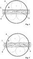
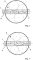
- FIGS. 4 to 7 schematically show the flow and the effect of various arrangements of openings 3 in the wall of the tube 4 on the open bottom 8 of the filter 6. Die FIGS. 4 to 7 thus show four different embodiments.
- the circumference of the filter 6 in the region of the surface of its open bottom 8 is shown schematically by a circle.
- the drawing has three adjacent, dashed circles, the center of which are marked by dash-dotted crosses.
- the tube 1 has three openings 3 which are arranged at an angle to the longitudinal direction 4 of the tube 1 (and thus to the flow direction L) and at an angle to the central axis 7 of the filter 6, so that the compressed gas exiting from the openings 3 intermittently strikes the open bottom 8 of the filter 6 in the areas of the dot-dashed crosses. Since the flow path from the opening 3 to the bottom 8 of the filter 6 widens conically, so that the enclosed by the dotted circles surfaces with the jerky emerging compressed air from the openings 3 acted upon. As already FIG.
- FIG. 5 The same situation is shown with four openings and four contiguous dot-dashed circles, in FIG. 6 with five openings, in which case the central opening has a smaller diameter than the two laterally left and right adjacent thereto openings in the wall of the tube 1, whereby the central circle has a smaller diameter and fits into the surrounding him four circles of larger diameter ,
- the situation is similar in the arrangement according to FIG. 7 with six openings.
- the distance B between the central axes 7 of successive filters 6 and the center of each group 2 or 2 'of openings 3 is not constant. Rather, this distance B, B ', B "decreases in the direction of flow L to account for the decreasing velocity of the gas within the tube 1. As this velocity decreases, the gas flows out of the apertures 3 of the tube at an increasingly perpendicular angle 1, so that the distance B between the central axes 7 of the filters 6 and the center of the groups 2 and 2 'is reduced in order to achieve a uniform loading of all the floors 8 of the filter 6.
- FIG. 11 shows the arrangement FIG. 10 rotated by 90 ° about the central axis 7, ie in the flow direction L of the tube 1.
- the center of the tube 1 is located at a distance h from the bottom 8 of the filter 6, as well as in FIG. 10 .
- the angles 12 and 12 ' here show the distance of the most distant openings 3 transversely to the flow direction L along the circumference of the tube 1.
- the various angles 12 and 12' arise due to the need, one of the in the FIGS. 4 to 7 shown loading pattern of the bottom 8 of the filter 6 to achieve.
- FIG. 8 is shown by an enlarged section through the wall of the tube 1, the individual openings 3 of each group 2 on a bore axis 9 (ie its central axis), which at an angle of less than 90 °, ie at an acute angle, based on both the central axis 7 of the filter 6 and on the longitudinal direction 4 of the tube 1, are arranged.
- a bore axis 9 ie its central axis
- the openings 3, with respect to the wall of the tube 1 or its longitudinal direction 4 run obliquely.
- the oblique course is, for example, realized by an oblique bore.
- This oblique course of the bore axis 9 of each opening 3 takes place counter to the flow direction L, so that the gas exiting through the openings 3 is deflected at the right choice of bore angle ultimately at a right angle from its flow direction L through the tube 1, if there are openings 3 passes.
- the openings 3 of each group 2 may have an additionally introduced tubular structure 10, which may be, for example, a sleeve with a stop.
- these tubular structures 10 are firmly connected to the wall of the tube 1 to a Release these items under the high pressure load to prevent. Through the tubular structure, the air can be directed more targeted in its exit direction.
- the openings 3 have a diameter between 4 and 20 mm, preferably again between 8 and 16 mm.
- the various groups 2 of the openings 3 may be made different with respect to the arrangement of the openings 3 within the group 2 and / or the inclination of the central axes 9 of at least one opening 3 with respect to the longitudinal direction 4 of the tube 1, i. not every group 2, 2 'and 2 "has to be formed identically.
- the filters 6 have a cylinder made of a filter material, which may also be closed with filter material opposite the open bottom 8 (not shown).
- Each group 2 of openings 3 is associated with the open inlet area or bottom 8 of a filter 6, so that the air flowing in pulses through the openings 3 into the interior pass each filter 6 and there can flow through the filter material, whereby on the outside (in the FIG. 11 Above), so the impure side of the filter 6, the adhering dirt are released and fall down.
- each group 2 The choice of the number of openings 3 and the constant number within each group 2 causes the pulse-like pressure in the inlet region of each cylindrical filter 6 is constant over the entire surface, so that no counterflow can form out of the filter to be cleaned.
- three openings 3 are already sufficient to keep such a pressure constant in the inlet area of the filter 6.
- Particularly advantageous is an embodiment with five openings, which are not exactly arranged in the tube 1 in the manner of a cube-five pattern, but distorted, as in FIG. 3 shown.
Landscapes
- Chemical & Material Sciences (AREA)
- Chemical Kinetics & Catalysis (AREA)
- Physics & Mathematics (AREA)
- Geometry (AREA)
- Filtering Of Dispersed Particles In Gases (AREA)
Priority Applications (1)
| Application Number | Priority Date | Filing Date | Title |
|---|---|---|---|
| PL19162171T PL3574973T3 (pl) | 2018-06-01 | 2019-03-12 | Układ filtrujący |
Applications Claiming Priority (1)
| Application Number | Priority Date | Filing Date | Title |
|---|---|---|---|
| DE102018113131.3A DE102018113131A1 (de) | 2018-06-01 | 2018-06-01 | Filteranordnung |
Publications (2)
| Publication Number | Publication Date |
|---|---|
| EP3574973A1 true EP3574973A1 (fr) | 2019-12-04 |
| EP3574973B1 EP3574973B1 (fr) | 2021-05-12 |
Family
ID=65766913
Family Applications (1)
| Application Number | Title | Priority Date | Filing Date |
|---|---|---|---|
| EP19162171.3A Active EP3574973B1 (fr) | 2018-06-01 | 2019-03-12 | Dispositif filtrant |
Country Status (6)
| Country | Link |
|---|---|
| US (1) | US20190366255A1 (fr) |
| EP (1) | EP3574973B1 (fr) |
| CN (1) | CN110548353B (fr) |
| DE (1) | DE102018113131A1 (fr) |
| DK (1) | DK3574973T3 (fr) |
| PL (1) | PL3574973T3 (fr) |
Citations (4)
| Publication number | Priority date | Publication date | Assignee | Title |
|---|---|---|---|---|
| AT377711B (de) * | 1983-07-04 | 1985-04-25 | Scheuch Alois | Vorrichtung zur abreinigung von aussen beaufschlagten filterschlaeuchen |
| US5062867A (en) * | 1989-12-14 | 1991-11-05 | Dustex Corporation | Method of retrofitting a dust collecting apparatus |
| US5395409A (en) * | 1994-02-03 | 1995-03-07 | Dustex Corporation | Dust collecting apparatus having reverse pulse filter cleaning capability |
| DE102015005414A1 (de) * | 2015-04-29 | 2016-11-03 | Carl Freudenberg Kg | Anordnung zur Abreinigung einer Filterpatrone und Düseneinheit |
Family Cites Families (9)
| Publication number | Priority date | Publication date | Assignee | Title |
|---|---|---|---|---|
| JPS5067514A (fr) | 1973-10-15 | 1975-06-06 | ||
| US3912173A (en) | 1974-04-25 | 1975-10-14 | Donald F Robichaux | Formation flushing tool |
| US5361452A (en) | 1993-04-29 | 1994-11-08 | Roger Horn | Reducer cannon cleaning device |
| JPH0716413A (ja) | 1993-06-30 | 1995-01-20 | Osamu Asai | 中空フィルタを有する集塵機 |
| US5938818A (en) * | 1997-08-22 | 1999-08-17 | Energy & Environmental Research Center Foundation | Advanced hybrid particulate collector and method of operation |
| CN101306285B (zh) * | 2008-07-10 | 2011-03-16 | 苏州工业园区协昌环保科技有限公司 | 脉冲喷吹袋式除尘器及其喷吹管的设计方法 |
| CN203648290U (zh) * | 2013-12-31 | 2014-06-18 | 苏州协昌环保科技股份有限公司 | 喷吹气流集中的喷吹管 |
| US10035095B2 (en) * | 2016-03-04 | 2018-07-31 | General Electric Company | Diverted pulse jet cleaning device and system |
| DE102016213769B4 (de) * | 2016-07-27 | 2022-06-09 | Audi Ag | Partikelfilter für eine Abgasanlage sowie Verfahren zum Herstellen eines Partikelfilters |
-
2018
- 2018-06-01 DE DE102018113131.3A patent/DE102018113131A1/de active Pending
-
2019
- 2019-03-12 PL PL19162171T patent/PL3574973T3/pl unknown
- 2019-03-12 DK DK19162171.3T patent/DK3574973T3/da active
- 2019-03-12 EP EP19162171.3A patent/EP3574973B1/fr active Active
- 2019-05-09 CN CN201910384102.0A patent/CN110548353B/zh active Active
- 2019-05-31 US US16/427,530 patent/US20190366255A1/en not_active Abandoned
Patent Citations (4)
| Publication number | Priority date | Publication date | Assignee | Title |
|---|---|---|---|---|
| AT377711B (de) * | 1983-07-04 | 1985-04-25 | Scheuch Alois | Vorrichtung zur abreinigung von aussen beaufschlagten filterschlaeuchen |
| US5062867A (en) * | 1989-12-14 | 1991-11-05 | Dustex Corporation | Method of retrofitting a dust collecting apparatus |
| US5395409A (en) * | 1994-02-03 | 1995-03-07 | Dustex Corporation | Dust collecting apparatus having reverse pulse filter cleaning capability |
| DE102015005414A1 (de) * | 2015-04-29 | 2016-11-03 | Carl Freudenberg Kg | Anordnung zur Abreinigung einer Filterpatrone und Düseneinheit |
Also Published As
| Publication number | Publication date |
|---|---|
| EP3574973B1 (fr) | 2021-05-12 |
| DE102018113131A1 (de) | 2019-12-05 |
| CN110548353B (zh) | 2021-08-17 |
| DK3574973T3 (da) | 2021-07-19 |
| PL3574973T3 (pl) | 2021-11-02 |
| CN110548353A (zh) | 2019-12-10 |
| US20190366255A1 (en) | 2019-12-05 |
Similar Documents
| Publication | Publication Date | Title |
|---|---|---|
| DE3727843C2 (de) | Vorrichtung zum Erzeugen von Flüssigkeitsstrahlen | |
| EP2952091B1 (fr) | Tuyau d'irrigation goutte à goutte doté d'éléments de dosage intégrés | |
| CH663730A5 (de) | Zylindrischer einsatz fuer eine zweistoff-zerstaeubungsduese. | |
| DE2514233A1 (de) | Duese fuer beregnungsanlagen | |
| EP3574973B1 (fr) | Dispositif filtrant | |
| DE4133973C2 (de) | Vorrichtung zum Versprühen eines Flüssigkeitsstrahls mit rotierender Achse auf einer konischen Fläche | |
| DE202018103090U1 (de) | Filteranordnung | |
| DE3333172A1 (de) | Vorrichtung zum abscheiden von fluessigkeitstropfen oder feinkoernigen feststoffen aus einem gasstrom | |
| DE102018105828A1 (de) | Vorrichtung zur Aufweitung eines Luftvolumenstroms | |
| DE29520069U1 (de) | Hydraulischer Durchsatzregler | |
| EP2383046B1 (fr) | Dispositif de buse | |
| EP3526385B1 (fr) | Rampe de jets d'eau pour le traitement de fibres par jets d'eau | |
| EP3526382B1 (fr) | Rampe de jets d'eau pour le traitement de fibres par jets d'eau | |
| EP3526384B1 (fr) | Rampe de jets d'eau pour le traitement de fibres par jets d'eau | |
| EP4140593B1 (fr) | Dispositif de buse et son procédé de fabrication | |
| EP3718455A1 (fr) | Buse de lave-vaisselle destinée au nettoyage des verres | |
| EP3669996B1 (fr) | Buse de distribution des liquides et dispositif de pulvérisation agricole | |
| WO2018068961A1 (fr) | Rampe de jets d'eau pour le traitement de fibres par jets d'eau | |
| DE102022124763A1 (de) | Düse mit konischem Strömungskanal | |
| DE102005004550A1 (de) | Plattenförmiges Stützelement | |
| DE102017002811A1 (de) | Strömungskanal mit einer Mischvorrichtung | |
| DD253666A1 (de) | Duesenkasten fuer eine vorrichtung zur waermebehandlung von warenbahnen, insbesondere textilbahnen | |
| CH368916A (de) | Luftbefeuchtungssystem, insbesondere für Ventilations- und Klimaanlagen | |
| DE102010019183A1 (de) | Düsenvorrichtung | |
| DE2637476B1 (de) | Abhitzedampferzeuger |
Legal Events
| Date | Code | Title | Description |
|---|---|---|---|
| PUAI | Public reference made under article 153(3) epc to a published international application that has entered the european phase |
Free format text: ORIGINAL CODE: 0009012 |
|
| STAA | Information on the status of an ep patent application or granted ep patent |
Free format text: STATUS: THE APPLICATION HAS BEEN PUBLISHED |
|
| AK | Designated contracting states |
Kind code of ref document: A1 Designated state(s): AL AT BE BG CH CY CZ DE DK EE ES FI FR GB GR HR HU IE IS IT LI LT LU LV MC MK MT NL NO PL PT RO RS SE SI SK SM TR |
|
| AX | Request for extension of the european patent |
Extension state: BA ME |
|
| STAA | Information on the status of an ep patent application or granted ep patent |
Free format text: STATUS: REQUEST FOR EXAMINATION WAS MADE |
|
| 17P | Request for examination filed |
Effective date: 20200604 |
|
| RBV | Designated contracting states (corrected) |
Designated state(s): AL AT BE BG CH CY CZ DE DK EE ES FI FR GB GR HR HU IE IS IT LI LT LU LV MC MK MT NL NO PL PT RO RS SE SI SK SM TR |
|
| GRAP | Despatch of communication of intention to grant a patent |
Free format text: ORIGINAL CODE: EPIDOSNIGR1 |
|
| STAA | Information on the status of an ep patent application or granted ep patent |
Free format text: STATUS: GRANT OF PATENT IS INTENDED |
|
| INTG | Intention to grant announced |
Effective date: 20201104 |
|
| GRAS | Grant fee paid |
Free format text: ORIGINAL CODE: EPIDOSNIGR3 |
|
| GRAA | (expected) grant |
Free format text: ORIGINAL CODE: 0009210 |
|
| STAA | Information on the status of an ep patent application or granted ep patent |
Free format text: STATUS: THE PATENT HAS BEEN GRANTED |
|
| AK | Designated contracting states |
Kind code of ref document: B1 Designated state(s): AL AT BE BG CH CY CZ DE DK EE ES FI FR GB GR HR HU IE IS IT LI LT LU LV MC MK MT NL NO PL PT RO RS SE SI SK SM TR |
|
| REG | Reference to a national code |
Ref country code: GB Ref legal event code: FG4D Free format text: NOT ENGLISH |
|
| REG | Reference to a national code |
Ref country code: CH Ref legal event code: EP |
|
| REG | Reference to a national code |
Ref country code: DE Ref legal event code: R096 Ref document number: 502019001391 Country of ref document: DE |
|
| REG | Reference to a national code |
Ref country code: IE Ref legal event code: FG4D Free format text: LANGUAGE OF EP DOCUMENT: GERMAN |
|
| REG | Reference to a national code |
Ref country code: AT Ref legal event code: REF Ref document number: 1391799 Country of ref document: AT Kind code of ref document: T Effective date: 20210615 |
|
| REG | Reference to a national code |
Ref country code: DK Ref legal event code: T3 Effective date: 20210714 |
|
| REG | Reference to a national code |
Ref country code: LT Ref legal event code: MG9D |
|
| REG | Reference to a national code |
Ref country code: SK Ref legal event code: T3 Ref document number: E 37870 Country of ref document: SK |
|
| REG | Reference to a national code |
Ref country code: NL Ref legal event code: MP Effective date: 20210512 |
|
| PG25 | Lapsed in a contracting state [announced via postgrant information from national office to epo] |
Ref country code: BG Free format text: LAPSE BECAUSE OF FAILURE TO SUBMIT A TRANSLATION OF THE DESCRIPTION OR TO PAY THE FEE WITHIN THE PRESCRIBED TIME-LIMIT Effective date: 20210812 Ref country code: FI Free format text: LAPSE BECAUSE OF FAILURE TO SUBMIT A TRANSLATION OF THE DESCRIPTION OR TO PAY THE FEE WITHIN THE PRESCRIBED TIME-LIMIT Effective date: 20210512 Ref country code: HR Free format text: LAPSE BECAUSE OF FAILURE TO SUBMIT A TRANSLATION OF THE DESCRIPTION OR TO PAY THE FEE WITHIN THE PRESCRIBED TIME-LIMIT Effective date: 20210512 Ref country code: LT Free format text: LAPSE BECAUSE OF FAILURE TO SUBMIT A TRANSLATION OF THE DESCRIPTION OR TO PAY THE FEE WITHIN THE PRESCRIBED TIME-LIMIT Effective date: 20210512 |
|
| PG25 | Lapsed in a contracting state [announced via postgrant information from national office to epo] |
Ref country code: IS Free format text: LAPSE BECAUSE OF FAILURE TO SUBMIT A TRANSLATION OF THE DESCRIPTION OR TO PAY THE FEE WITHIN THE PRESCRIBED TIME-LIMIT Effective date: 20210912 Ref country code: GR Free format text: LAPSE BECAUSE OF FAILURE TO SUBMIT A TRANSLATION OF THE DESCRIPTION OR TO PAY THE FEE WITHIN THE PRESCRIBED TIME-LIMIT Effective date: 20210813 Ref country code: LV Free format text: LAPSE BECAUSE OF FAILURE TO SUBMIT A TRANSLATION OF THE DESCRIPTION OR TO PAY THE FEE WITHIN THE PRESCRIBED TIME-LIMIT Effective date: 20210512 Ref country code: NO Free format text: LAPSE BECAUSE OF FAILURE TO SUBMIT A TRANSLATION OF THE DESCRIPTION OR TO PAY THE FEE WITHIN THE PRESCRIBED TIME-LIMIT Effective date: 20210812 Ref country code: RS Free format text: LAPSE BECAUSE OF FAILURE TO SUBMIT A TRANSLATION OF THE DESCRIPTION OR TO PAY THE FEE WITHIN THE PRESCRIBED TIME-LIMIT Effective date: 20210512 Ref country code: SE Free format text: LAPSE BECAUSE OF FAILURE TO SUBMIT A TRANSLATION OF THE DESCRIPTION OR TO PAY THE FEE WITHIN THE PRESCRIBED TIME-LIMIT Effective date: 20210512 Ref country code: PT Free format text: LAPSE BECAUSE OF FAILURE TO SUBMIT A TRANSLATION OF THE DESCRIPTION OR TO PAY THE FEE WITHIN THE PRESCRIBED TIME-LIMIT Effective date: 20210913 |
|
| PG25 | Lapsed in a contracting state [announced via postgrant information from national office to epo] |
Ref country code: NL Free format text: LAPSE BECAUSE OF FAILURE TO SUBMIT A TRANSLATION OF THE DESCRIPTION OR TO PAY THE FEE WITHIN THE PRESCRIBED TIME-LIMIT Effective date: 20210512 |
|
| PG25 | Lapsed in a contracting state [announced via postgrant information from national office to epo] |
Ref country code: ES Free format text: LAPSE BECAUSE OF FAILURE TO SUBMIT A TRANSLATION OF THE DESCRIPTION OR TO PAY THE FEE WITHIN THE PRESCRIBED TIME-LIMIT Effective date: 20210512 Ref country code: EE Free format text: LAPSE BECAUSE OF FAILURE TO SUBMIT A TRANSLATION OF THE DESCRIPTION OR TO PAY THE FEE WITHIN THE PRESCRIBED TIME-LIMIT Effective date: 20210512 Ref country code: SM Free format text: LAPSE BECAUSE OF FAILURE TO SUBMIT A TRANSLATION OF THE DESCRIPTION OR TO PAY THE FEE WITHIN THE PRESCRIBED TIME-LIMIT Effective date: 20210512 Ref country code: RO Free format text: LAPSE BECAUSE OF FAILURE TO SUBMIT A TRANSLATION OF THE DESCRIPTION OR TO PAY THE FEE WITHIN THE PRESCRIBED TIME-LIMIT Effective date: 20210512 |
|
| REG | Reference to a national code |
Ref country code: DE Ref legal event code: R097 Ref document number: 502019001391 Country of ref document: DE |
|
| PLBE | No opposition filed within time limit |
Free format text: ORIGINAL CODE: 0009261 |
|
| STAA | Information on the status of an ep patent application or granted ep patent |
Free format text: STATUS: NO OPPOSITION FILED WITHIN TIME LIMIT |
|
| 26N | No opposition filed |
Effective date: 20220215 |
|
| PG25 | Lapsed in a contracting state [announced via postgrant information from national office to epo] |
Ref country code: IS Free format text: LAPSE BECAUSE OF FAILURE TO SUBMIT A TRANSLATION OF THE DESCRIPTION OR TO PAY THE FEE WITHIN THE PRESCRIBED TIME-LIMIT Effective date: 20210912 Ref country code: AL Free format text: LAPSE BECAUSE OF FAILURE TO SUBMIT A TRANSLATION OF THE DESCRIPTION OR TO PAY THE FEE WITHIN THE PRESCRIBED TIME-LIMIT Effective date: 20210512 |
|
| PG25 | Lapsed in a contracting state [announced via postgrant information from national office to epo] |
Ref country code: MC Free format text: LAPSE BECAUSE OF FAILURE TO SUBMIT A TRANSLATION OF THE DESCRIPTION OR TO PAY THE FEE WITHIN THE PRESCRIBED TIME-LIMIT Effective date: 20210512 |
|
| REG | Reference to a national code |
Ref country code: CH Ref legal event code: PL |
|
| PG25 | Lapsed in a contracting state [announced via postgrant information from national office to epo] |
Ref country code: LU Free format text: LAPSE BECAUSE OF NON-PAYMENT OF DUE FEES Effective date: 20220312 Ref country code: LI Free format text: LAPSE BECAUSE OF NON-PAYMENT OF DUE FEES Effective date: 20220331 Ref country code: IE Free format text: LAPSE BECAUSE OF NON-PAYMENT OF DUE FEES Effective date: 20220312 Ref country code: CH Free format text: LAPSE BECAUSE OF NON-PAYMENT OF DUE FEES Effective date: 20220331 |
|
| PG25 | Lapsed in a contracting state [announced via postgrant information from national office to epo] |
Ref country code: MK Free format text: LAPSE BECAUSE OF FAILURE TO SUBMIT A TRANSLATION OF THE DESCRIPTION OR TO PAY THE FEE WITHIN THE PRESCRIBED TIME-LIMIT Effective date: 20210512 Ref country code: CY Free format text: LAPSE BECAUSE OF FAILURE TO SUBMIT A TRANSLATION OF THE DESCRIPTION OR TO PAY THE FEE WITHIN THE PRESCRIBED TIME-LIMIT Effective date: 20210512 |
|
| PG25 | Lapsed in a contracting state [announced via postgrant information from national office to epo] |
Ref country code: HU Free format text: LAPSE BECAUSE OF FAILURE TO SUBMIT A TRANSLATION OF THE DESCRIPTION OR TO PAY THE FEE WITHIN THE PRESCRIBED TIME-LIMIT; INVALID AB INITIO Effective date: 20190312 |
|
| PG25 | Lapsed in a contracting state [announced via postgrant information from national office to epo] |
Ref country code: MT Free format text: LAPSE BECAUSE OF FAILURE TO SUBMIT A TRANSLATION OF THE DESCRIPTION OR TO PAY THE FEE WITHIN THE PRESCRIBED TIME-LIMIT Effective date: 20210512 |
|
| REG | Reference to a national code |
Ref country code: AT Ref legal event code: MM01 Ref document number: 1391799 Country of ref document: AT Kind code of ref document: T Effective date: 20240312 |
|
| PGFP | Annual fee paid to national office [announced via postgrant information from national office to epo] |
Ref country code: DE Payment date: 20250415 Year of fee payment: 7 |
|
| PGFP | Annual fee paid to national office [announced via postgrant information from national office to epo] |
Ref country code: IT Payment date: 20250331 Year of fee payment: 7 |
|
| PG25 | Lapsed in a contracting state [announced via postgrant information from national office to epo] |
Ref country code: AT Free format text: LAPSE BECAUSE OF NON-PAYMENT OF DUE FEES Effective date: 20240312 |
|
| PGFP | Annual fee paid to national office [announced via postgrant information from national office to epo] |
Ref country code: GB Payment date: 20260317 Year of fee payment: 8 |
|
| PGFP | Annual fee paid to national office [announced via postgrant information from national office to epo] |
Ref country code: DK Payment date: 20260323 Year of fee payment: 8 |
|
| PGFP | Annual fee paid to national office [announced via postgrant information from national office to epo] |
Ref country code: AT Payment date: 20260410 Year of fee payment: 5 |
|
| PGFP | Annual fee paid to national office [announced via postgrant information from national office to epo] |
Ref country code: BE Payment date: 20260323 Year of fee payment: 8 |
|
| PGFP | Annual fee paid to national office [announced via postgrant information from national office to epo] |
Ref country code: FR Payment date: 20260324 Year of fee payment: 8 |
|
| PGFP | Annual fee paid to national office [announced via postgrant information from national office to epo] |
Ref country code: TR Payment date: 20260305 Year of fee payment: 8 |
|
| PGFP | Annual fee paid to national office [announced via postgrant information from national office to epo] |
Ref country code: CZ Payment date: 20260227 Year of fee payment: 8 |
|
| PGFP | Annual fee paid to national office [announced via postgrant information from national office to epo] |
Ref country code: PL Payment date: 20260227 Year of fee payment: 8 |
|
| PGFP | Annual fee paid to national office [announced via postgrant information from national office to epo] |
Ref country code: SK Payment date: 20260309 Year of fee payment: 8 |