EP3575014A1 - Tube cylindrique pour amortisseur et son procédé de fabrication - Google Patents
Tube cylindrique pour amortisseur et son procédé de fabrication Download PDFInfo
- Publication number
- EP3575014A1 EP3575014A1 EP18174630.6A EP18174630A EP3575014A1 EP 3575014 A1 EP3575014 A1 EP 3575014A1 EP 18174630 A EP18174630 A EP 18174630A EP 3575014 A1 EP3575014 A1 EP 3575014A1
- Authority
- EP
- European Patent Office
- Prior art keywords
- tube
- joining part
- joining
- präzisrohrrohling
- precision
- Prior art date
- Legal status (The legal status is an assumption and is not a legal conclusion. Google has not performed a legal analysis and makes no representation as to the accuracy of the status listed.)
- Withdrawn
Links
- 239000006096 absorbing agent Substances 0.000 title claims abstract description 38
- 230000035939 shock Effects 0.000 title claims abstract description 38
- 238000004519 manufacturing process Methods 0.000 title claims abstract description 29
- 238000000034 method Methods 0.000 title claims description 32
- 238000005304 joining Methods 0.000 claims abstract description 47
- 239000000463 material Substances 0.000 claims description 33
- 238000006073 displacement reaction Methods 0.000 claims description 15
- 230000004323 axial length Effects 0.000 claims description 13
- 238000001953 recrystallisation Methods 0.000 claims description 6
- 230000000717 retained effect Effects 0.000 claims description 4
- 230000006835 compression Effects 0.000 description 11
- 238000007906 compression Methods 0.000 description 11
- 230000008569 process Effects 0.000 description 7
- 239000007769 metal material Substances 0.000 description 6
- 239000012530 fluid Substances 0.000 description 5
- 238000003754 machining Methods 0.000 description 5
- 230000009467 reduction Effects 0.000 description 5
- 238000013016 damping Methods 0.000 description 4
- 238000002844 melting Methods 0.000 description 4
- 230000008018 melting Effects 0.000 description 4
- 238000012545 processing Methods 0.000 description 4
- 238000007514 turning Methods 0.000 description 4
- 230000015572 biosynthetic process Effects 0.000 description 3
- 239000003795 chemical substances by application Substances 0.000 description 3
- 238000011161 development Methods 0.000 description 3
- 230000018109 developmental process Effects 0.000 description 3
- 239000011159 matrix material Substances 0.000 description 3
- 238000007789 sealing Methods 0.000 description 3
- 239000011343 solid material Substances 0.000 description 3
- 238000003860 storage Methods 0.000 description 3
- 230000000694 effects Effects 0.000 description 2
- 239000000834 fixative Substances 0.000 description 2
- 238000003780 insertion Methods 0.000 description 2
- 230000037431 insertion Effects 0.000 description 2
- 238000010409 ironing Methods 0.000 description 2
- 230000002093 peripheral effect Effects 0.000 description 2
- 238000005482 strain hardening Methods 0.000 description 2
- 230000009471 action Effects 0.000 description 1
- 239000003638 chemical reducing agent Substances 0.000 description 1
- 238000002485 combustion reaction Methods 0.000 description 1
- 239000002131 composite material Substances 0.000 description 1
- 150000001875 compounds Chemical class 0.000 description 1
- 238000001816 cooling Methods 0.000 description 1
- 238000013461 design Methods 0.000 description 1
- 238000005516 engineering process Methods 0.000 description 1
- 238000004898 kneading Methods 0.000 description 1
- 230000014759 maintenance of location Effects 0.000 description 1
- 230000007246 mechanism Effects 0.000 description 1
- 239000002184 metal Substances 0.000 description 1
- 238000003825 pressing Methods 0.000 description 1
- 239000007787 solid Substances 0.000 description 1
- 239000000725 suspension Substances 0.000 description 1
- 230000008719 thickening Effects 0.000 description 1
Images


Classifications
-
- B—PERFORMING OPERATIONS; TRANSPORTING
- B21—MECHANICAL METAL-WORKING WITHOUT ESSENTIALLY REMOVING MATERIAL; PUNCHING METAL
- B21K—MAKING FORGED OR PRESSED METAL PRODUCTS, e.g. HORSE-SHOES, RIVETS, BOLTS OR WHEELS
- B21K25/00—Uniting components to form integral members, e.g. turbine wheels and shafts, caulks with inserts, with or without shaping of the components
-
- B—PERFORMING OPERATIONS; TRANSPORTING
- B23—MACHINE TOOLS; METAL-WORKING NOT OTHERWISE PROVIDED FOR
- B23P—METAL-WORKING NOT OTHERWISE PROVIDED FOR; COMBINED OPERATIONS; UNIVERSAL MACHINE TOOLS
- B23P11/00—Connecting or disconnecting metal parts or objects by metal-working techniques not otherwise provided for
- B23P11/005—Connecting or disconnecting metal parts or objects by metal-working techniques not otherwise provided for by expanding or crimping
-
- B—PERFORMING OPERATIONS; TRANSPORTING
- B21—MECHANICAL METAL-WORKING WITHOUT ESSENTIALLY REMOVING MATERIAL; PUNCHING METAL
- B21D—WORKING OR PROCESSING OF SHEET METAL OR METAL TUBES, RODS OR PROFILES WITHOUT ESSENTIALLY REMOVING MATERIAL; PUNCHING METAL
- B21D39/00—Application of procedures in order to connect objects or parts, e.g. coating with sheet metal otherwise than by plating; Tube expanders
- B21D39/04—Application of procedures in order to connect objects or parts, e.g. coating with sheet metal otherwise than by plating; Tube expanders of tubes with tubes; of tubes with rods
-
- F—MECHANICAL ENGINEERING; LIGHTING; HEATING; WEAPONS; BLASTING
- F16—ENGINEERING ELEMENTS AND UNITS; GENERAL MEASURES FOR PRODUCING AND MAINTAINING EFFECTIVE FUNCTIONING OF MACHINES OR INSTALLATIONS; THERMAL INSULATION IN GENERAL
- F16F—SPRINGS; SHOCK-ABSORBERS; MEANS FOR DAMPING VIBRATION
- F16F2226/00—Manufacturing; Treatments
-
- F—MECHANICAL ENGINEERING; LIGHTING; HEATING; WEAPONS; BLASTING
- F16—ENGINEERING ELEMENTS AND UNITS; GENERAL MEASURES FOR PRODUCING AND MAINTAINING EFFECTIVE FUNCTIONING OF MACHINES OR INSTALLATIONS; THERMAL INSULATION IN GENERAL
- F16F—SPRINGS; SHOCK-ABSORBERS; MEANS FOR DAMPING VIBRATION
- F16F9/00—Springs, vibration-dampers, shock-absorbers, or similarly-constructed movement-dampers using a fluid or the equivalent as damping medium
- F16F9/32—Details
- F16F9/3207—Constructional features
- F16F9/3235—Constructional features of cylinders
Definitions
- the invention relates to a method of manufacturing a cylinder tube, i. a cylindrical hollow tube, in particular recuperzisrohrs or in recuperzisrohrohn, which is suitable for example as a shock absorber tube, especially as a shock absorber inner tube for a Zweirohr Stammdämpfer- / strut system for motor vehicles with a trained as a hollow tube recuperzisrohrrohling with the Rezisrohrrohling at least in a joining region coaxially surrounding cylindrical and / or annular Joining part for forming a one with respect to the Rezisrohrrohling increased wall thickness having thick wall section is joined.
- a shock absorber tube especially as a shock absorber inner tube for a Zweirohr Stammer- / strut system for motor vehicles with a trained as a hollow tube recuperrohling with the recuperzisrohrrohling at least in a joining region coaxially surrounding cylindrical and / or annular Joining part for forming a one with respect to the recuperzisrohrroh
- the invention is directed to a cylinder tube, in particular produced by the above method, which is suitable as a shock absorber tube, in particular as a shock absorber inner tube for a Zweirohr Stammdämpfer- / strut system for motor vehicles, with an increased wall thickness thick wall section.
- two-pipe shock absorber systems are formed with two concentrically nested tubes, an inner tube and an outer tube, wherein the inner tube, the actual cylinder tube, ie a cylindrical hollow tube, forms the piston space filled with a shock absorber fluid for a piston.
- the arranged as a compensation space between the inner tube and the outer tube annulus is mostly also filled with shock absorber fluid. Only in the upper part of a compressible gas bubble is provided, which serves to provide the displaced by the more or less plunging piston shock absorber fluid due to their compressibility space.
- shock absorber pipes in the prior art are usually made of precision tube blanks, in particular according to DIN EN 10305-2 (November 2002) or DIN EN 10305-3 (February 2003), produced by various manufacturing processes.
- Particularly suitable for this purpose are so-called axial cold forming processes, wherein a plastic deformation of a metallic material below its recrystallization temperature, which is usually 40-50% of the melting temperature, in particular by means of stretching, drawing, upsetting and / or expansion takes place.
- a generic hydraulic twin-tube shock absorber for motor vehicles is from the DE 37 219 15 A1 known. This has an outer casing (outer tube) and a recorded in this cylinder (inner tube), whose interior serves as a working space for the piston stroke.
- a space defined between the outer shell and the cylinder is filled with gas as well as oil and forms a storage space which is separated from the interior of the cylinder by a bottom valve attached to the lower end thereof.
- the bottom valve is provided with a throttle opening and a return opening, wherein oil flowing through the throttle opening generates a damping force at the compression (compression stroke) of the damper.
- the piston slidably inserted into the cylinder divides the interior of the cylinder into two chambers. During rebound (expansion stroke) of the damper, a damping force is generated by flowing oil between the two chambers.
- an additional sealing mechanism should be provided.
- the shock absorber inner tube for a hydraulic twin-tube shock absorber to take.
- the shock absorber inner tube is made in several cold forming steps, wherein a first tube portion is formed by upsetting to a thick wall portion with respect to the Rezisrohrrohling increased wall thickness and another, second tube portion, in particular a pipe end is formed by means of an expanding mandrel with a pipe expansion.
- the thick wall section and the flared tube end each are formed with a tube outer diameter, which is substantially the tube inner diameter of an outer tube for the same twin-tube shock absorber corresponds to, for example, to weld the flared end of the inner tube and the outer tube together.
- the thick wall section can act as an annular web and be provided with an annular groove for receiving a sealing ring, to seal the inner tube and the outer tube liquid-tight, in particular oil-tight, against each other.
- the EP 0 944 443 B1 discloses, for example, a method for producing composite pipes, in particular so-called internally plated pipes.
- a second inner tube is inserted with a smaller outer diameter in an outer, thick-walled tube made of a high-strength metallic material.
- the inner tube is made of a likewise metallic material and has a smaller wall thickness than the outer tube.
- a securing element which is intended to prevent a radial displacement of two tubes arranged coaxially with one another is proposed.
- a camshaft with a coaxially arranged in an outer shaft inner shaft, wherein the outer shaft is formed as a circular cylindrical tube.
- the axial end arranged to the inner shaft securing device is the Fixation of the inner shaft radially to the outer shaft.
- the inner shaft has a radially inwardly recessed peripheral step, which forms a seat for the securing element.
- the fuse element can be shrunk by means of shrink fit on the inner shaft and so firmly connected to this.
- the joint connection is realized here between the annular securing element and the inner shaft formed of solid material.
- the concerns DE 199 57 508 C1 a device for joining provided with a through-hole joining parts, such as cams on hollow sections, for example, a hollow shaft to form a camshaft.
- a through-hole joining parts such as cams on hollow sections, for example, a hollow shaft to form a camshaft.
- the cams by partial hydroforming by means of a pressure lance leading expansion lance.
- the expanding lance is inserted into the hollow shaft and widens it by means of fluid internal high pressure at the point at which the cams are pushed in order to obtain a joint realized as a press connection.
- a disadvantage of this method is that the hollow profile is widened plastically by means of the fluidic internal high pressure at the joint, whereby its material properties, in particular its strength values deteriorate.
- this object is achieved in that a joint connection between the Rezisrohrrohling and the adherend to form the thick wall portion by local Cold forming of the Joining part is formed positively and / or non-positively within the joining region.
- cylinder tube which is suitable as a shock absorber tube, in particular as a shock absorber inner tube for a Zweiirohritzdämpfer- / strut system for motor vehicles, suitable by the thick wall section as a joint connection between a Rezisrohrrohling and a cylindrical and / or annular joining part is formed, wherein the joining part coaxially surrounds the precision tube blank in a joining region and in the region of the thick wall section.
- the invention is not limited to the use of the inventive method for producing a cylinder tube for shock absorber systems. According to the invention, any application is possible, in which a cylindrical hollow tube with a (locally) thickened wall section, a (local) thick-wall section, in precision tube quality or as a precision tube product is required.
- a force and / or form fit corresponding to the requirements imposed on a precision tube product can be obtained in the region of the thick wall section.
- the cylinder tube is suitable for use as a shock absorber tube, in particular as a shock absorber inner tube
- the joint connection is formed by a cold forming process or the joining part is locally cold formed.
- the Cold forming is the, preferably metallic, joining part formed by the action of force, ie the geometry of the joining part is changed plastically.
- the cold-forming process does not exceed the recrystallization temperature of the material, which is usually 40-50% of the melting temperature, in particular of the metallic material.
- the recrystallization temperature of the material which is usually 40-50% of the melting temperature, in particular of the metallic material.
- a positive and / or positive connection can be obtained locally in the joining region between the precision tube blank and the joining part, which then forms the thick-wall section of a cylinder tube.
- the obtained cylinder tube and its thick-walled portion are further processable and / or usable in the same manner as an integrally manufactured cylinder tube with a thick-walled portion formed by, for example, swaging.
- the thick-walled section can be spaced at any axial sections of the precision tube blank, also from its end sections and / or tube ends, and formed in any desired axial length without substantial changes being made in the method sequence.
- the present manufacturing process is more flexible and less expensive due to the no longer necessary machining of metal to form a compression edge.
- a recuperatorrohling can be used with a comparison with the conventional manufacturing process lower wall thickness.
- the determination of the position of the thick wall section is effected by fixing the joining region, within which the cylindrical and / or annular joining part is arranged coaxially with the precision tube blank.
- the axial length of the thick wall section can be determined by the axial length of the cylindrical and / or annular joining part used.
- the inner wall of an inner tube for a two-tube shock absorber system is a smooth, especially groove-free surface essential to realize an unobstructed sliding of the piston moving up and down in it.
- the joining part is forced during the cold forming in a stroke in a stroke direction by a die and / or Reduzierring, locally within the joining region, an axial and / or a radial material displacement of the joining part to form the form and / or non-positive joint connection is obtained.
- the recuperatively forming is held during cold forming by means of a, in particular designed as clamping jaws, fixing, the recuperatorrohling is held loose and / or play in the working stroke by means of the fixing means to allow an axial positional displacement of procurzisrohrrohlings.
- the precision tube blank may be supported during the working stroke by means of a mandrel disposed within the precision tube blank to counteract and stabilize a force transferred to the precision tube blank during cold forming of the adherend.
- the joining area is then arranged between the die and / or reducing ring and the mandrel.
- the fixing means which is designed in particular as a counter-jaw surrounding clamping jaws arranged.
- the cylindrical and / or annular joining part can be supported on supporting edges of the fixing.
- the adherend is forced through the die and / or reducer ring, thereby effecting cold working with axial and / or radial material misalignment. Due to the axial material offset, the axial length of the supporting edge of the fixing means supporting the joining part is increased, wherein the positive and / or non-positively between the mandrel and the joining part or the die and / or Reduzierring "trapped" Rezisrohrrohling within the fixing axially offset, in particular slightly raised.
- the precision tube blank In order to avoid damage and / or a reduction in quality of the precision tube blank during cold working in the working stroke, it is expedient for the precision tube blank to be held loosely and / or with play by the fixing means.
- the precision tube blank is held firmly and / or without play by the fixing means, in particular by pulling out the mandrel from inside the precision tube blank and / or passing the joining part with the precision tube blank, in particular the joining region To allow Matrizen- and / or Reduzierring.
- a fixing device designed as a clamping jaw it is possible, for example, to move it further radially in the direction of the precision tube blank, in particular to close it and to retain the precision tube blank by force and / or positive locking.
- An advantageous embodiment of the method provides that the recuperatorrohling is formed within the joining region with an annular groove or a circumferential receptacle and then during the cold forming a radial material displacement of the joining part in the annular groove or circumferential recording for the formation of the positive joining connection is obtained.
- an axial length of the cylindrical and / or annular joining part is selected to be greater than an axial length of the annular groove or circumferential receptacle formed within the joining area on the precision tube blank and during the cold forming a radial material displacement of the joining part into the annular groove or circumferential receptacle for the formation of the obtains a positive joint connection.
- the joining part and the precision tube blank In order to form a positive connection between the joining part and the precision tube blank, it can first be formed within the joining region with an annular groove or a peripheral receptacle in any desired geometric configuration, which is produced for example by machining material, in particular by turning.
- the joining area with the precision tube blank and the joining part In the working stroke, the joining area with the precision tube blank and the joining part can be forced through a die and / or reducing ring to effect cold forming. Due to the radially to the joining part inside annular groove or circumferential recording in this case a material offset of the joining part takes place in the radial direction in the annular groove or circumferential recording in place.
- the annular groove or circumferential receptacle can thus be "filled” with the adherend so that a positive connection between this and the recuperzisrohrrohling arises.
- the adherend is heated before and / or during cold forming to form and / or improve the frictional joining connection to a temperature below the recrystallization temperature, which is usually 40-50% of the melting temperature of the adherend.
- a material strength of the precision tube blank is selected to be higher than a material strength of the joining part.
- a material strength of the joining part is selected to be higher than a material strength of the joining part.
- the joining part before it is arranged coaxially in the region of the joint to the recuperzisrohrrohling is preheated to a temperature of about 70 ° C -80 ° C.
- the joining part is also heated during cold forming by the forces acting on. After completion of the cold forming, in particular after the return stroke, the joining part cools, whereby, in particular in addition to the positive locking a non-positive garment seat is obtained in the sense of a press connection and / or the non-positive connection is improved.
- damping fluid in particular oil
- the temperature of the joining part in particular of the metallic joining part, always remains below its recrystallization temperature, which is usually 40-50% of the melting temperature.
- the strength values of the material can be maintained virtually unchanged during cold forming.
- An advantageous embodiment of the manufacturing method is characterized in that a Rohrendabêt or a pipe end of the Rezisrohrrohlings is formed before the cold forming with a pipe expansion, the pipe expansion has a relation to the procurzisrohrrohling larger pipe diameter.
- the joining part coaxially surrounding the precision tube blank is forced in a working stroke in a stroke direction by a die and / or reducing ring and during the working stroke by means of one, in particular as two Clamping jaws trained, fixing means is loosely and / or kept at play to allow axial positional displacement of the procurzisrohrrohlings, and is guided in a following on the working stroke return stroke in a lifting direction opposite return direction through the die and / or Reduzierring, wherein the procurzisrohrrohling is restrained by the fixer during the return stroke by abutting the tube extension at a retention edge of the fixative.
- the pipe expansion is preferably also transformed by a cold forming process, a so-called expansion, whereby losses in the material quality, in particular the strength of, in particular metallic Rezisrohrrohlings be avoided.
- the pipe end can be expanded in a range of 10-20%, preferably 17%.
- the positioning of the joining part to be attached to the precision tube blank is fixed solely by the geometric design or dimensions of the fixing means, so that preferably only the fixing agent is used to produce different cylinder tubes, in particular with thick-wall sections formed at different axial positions and / or with or without a tube expansion is.
- the joining part which after cold forming forms the thick-wall section, which has an increased wall thickness relative to the precision tube blank, is formed with a receiving groove, in particular for receiving a ring seal.
- the joint connection between the procurzisrohrrohling and the adherend is made so solid due to the cold-formed, positive or non-positive, in particular positive and non-positive connection, that the cylinder wall having the thick wall portion, further processed and / or can be used in the same manner as a cylinder tube made of a solid material with an example obtained by upsetting thick wall section.
- the thick-wall section can be provided with a receiving groove for receiving a ring seal by means of metal-removing material processing, preferably by means of turning.
- the cylinder tube according to the invention is also characterized in an advantageous embodiment by the fact that the thick wall portion, which compared to the Rezisrohrrohling has an increased wall thickness, with a receiving groove, in particular for receiving a ring seal is formed.
- the thick wall portion forming joint connection between the Rezisrohrrohling and the cylindrical and / or annular joining part and / or the joining area is formed positively and / or non-positively.
- the thick wall portion forming joint connection between the Rezisrohrrohling and the cylindrical and / or annular joining part is not visually recognizable.
- the cylinder tube according to the invention in particular produced by the method according to the invention, is not to be distinguished from a conventional cylinder tube, the thick-walled section of which has been shaped, for example, by compression.
- the manufacturing method according to the invention is faster, easier and cheaper to perform compared to known from the prior art method, since only a few processing steps of Retriggerrohlings and / or the joining part are made. Both the axial position with respect to the recuperzisrohrrohlings and the axial length of the joining part can in a simple manner by the embodiment a fixing agent to which the joining part bears during the cold forming, or be set over the axial length of the joining part used.
- the radial extent or the thickness of the thick wall section can also be adjusted via the geometric dimension of the joining part.
- the cylinder tube according to the invention is generally less expensive than known from the prior art cylinder tubes with thick wall section, since this is not formed from the refzisrohrrohling itself but added as a cheaper joining part. Additional material losses, for example by forming a compression edge, can also be avoided. Due to the cold forming according to the invention for the formation of the joint connection, the strength value of the precision tube blank remains unchanged.
- the inventive manufacturing method according to claim 1 and the cylinder tube according to the invention, d. H. the cylindrically shaped hollow tube, according to claim 12 for other purposes, as the production of or use as a shock absorber tube, in particular shock absorber inner tube may be suitable.
- the production method according to the invention can be used for any precision tube products which provide a local thickening or increase in the wall thickness or thick-wall section.
- the joining compound according to the invention produced by forming technology is in each case suitable for fulfilling the requirements imposed on precision tube products with regard to the force / form fit.
- FIG. 1 shows an exemplary representation of the method according to the invention, in which a procurzisionsrohrrohling 100 in a Fixing 200 is arranged.
- a first tube end 110 of the precision tube blank 100 is formed with a tube extension 111, which was preferably cold-formed by expansion.
- the precision tube blank 100 has an annular groove or circumferential receptacle 121, which has been formed, in particular by machining material, preferably by turning, on the outside of the casing of the precision tube blank 100.
- the fixing means 200 is arranged on a base plate 210 and has two hollow cylindrical clamping jaws 220 mounted so as to be movable radially relative to one another.
- the inner surface of the hollow cylindrical clamping jaws 220 is adapted in its geometry of the tube extension 111 of the precision tube blank 100. Furthermore, the fixing means 200 has a counter-part 230 which is coaxially surrounded by the clamping jaws 220.
- the first tube end 110 of the precision tube blank 100 formed with the tube expansion 111 is, in turn, arranged coaxially between the clamping jaws 220 and the counter-tooth 230.
- the clamping jaws 220 are movable radially along the double arrow A.
- FIG. 2 an exemplary representation of the method according to the invention is shown, in which a cylindrical and / or annular joining part 300 coaxially surrounding the precision tube blank 100 is supported on the fixing means 200.
- the clamping jaws 220 of the fixing means 200 are moved radially along the double arrow A in the direction of the precision tube blank 100 in order to keep the precision tube blank 100 in the region of the first tube end 110.
- the precision tube blank 100 is loosely held by the fixation means 200, or the first tube end 110 of the precision tube blank 100 is disposed coaxially between the jaws 220 and the counter-tooth 230 in both the radial and axial directions.
- the cylindrical and / or annular joining part 300 is the precision tube blank 100 disposed coaxially surrounding within the joining region 120, wherein the joining part 300 is supported on a support edge 240 of the clamping jaws 220.
- the joining part 300 is loosely pushed onto the precision tube blank 100 and is held and / or positioned within the joining region 120 by the fixing means 200, in particular by the supporting edges 230 of the clamping jaws 220, whereby the axial position of the later formed thick wall section with respect.
- Precision tube blank 100 is set.
- FIG. 3 shows an exemplary representation of the method according to the invention, which is to remove a provided for joining the procurzisrohrrohlings 100 with the joining part 300 tool head 400.
- the tool head 400 is axially movable along the double arrow B in the direction of the bottom plate 210, in particular lowerable.
- the tool head 400 comprises a head plate 410, a receiving block 420 with a cylindrical recess for receiving a spring element 430, in particular a compression spring element, a matrix 441 connected to a ring console 441 and / or Reduzierring 440 and a support mandrel 450, which is held by a mandrel 451.
- the mandrel 450 is already partially inserted into the interior of the precision tube blank 100 and is flush with its inner surface or the support mandrel 450 is arranged without play within the Rezisrohrrohlings 100.
- the spring element 430 on which the support mandrel 450 is supported by means of the mandrel rod 451, is unloaded and / or not deflected.
- the matrix and / or reducing ring 440 is arranged surrounding the support mandrel 450, so that a second pipe end 130 of the precision tube blank 100, which protrudes from the fixing means 200, coaxially between the support mandrel 450 and the die and / or Reduzierring 440 is arranged. Due to the radial clearance with which the precision tube blank 100 is held within the fixing means 200, play-free insertion of the support mandrel 450 into the second tube end 130 of the precision tube blank 100 is facilitated.
- FIG. 4 An exemplary representation of the method according to the invention, in which the tool head 400 is moved in a stroke direction during a working stroke, is the FIG. 4 refer to.
- the tool head 400 is moved in the direction of the precision tube blank 100 held by the fixing means 200 or in the direction of the base plate 210, in particular the tool head 400 is lowered until the support mandrel 450 strikes against the counter-tooth 230 coaxially arranged within the precision tube blank 100.
- the height of the counter-cam 230 or its axial length is selected such that the support mandrel 450 radially supports the precision tube blank 100 within the joining region 120.
- the Positioning of the attached to the recuperzisrohrrohling 100 joining part 300 is thus festlebgar alone by the geometric configuration or the dimensions of the fixative 200, so preferably for producing different cylinder tubes, especially with formed at different positions thick wall sections and / or without tube extension 111 exclusively Changing the fixer 200 and use of the same tool head 400 is possible.
- the tool head 400 is further moved in the direction of the bottom plate 210 during the power stroke, in particular lowered, wherein the spring element 430, in particular the compression spring element, loaded by the mandrel bar 451 and / or is deflected.
- the die and / or reduction ring 440 is moved further in the direction of the base plate 210, in particular lowered, whereas the support mandrel 450 is retained by the counter-element 230 in an unchanged position.
- the die and / or reduction ring 440 thus moves axially relative to the support mandrel 450.
- the tool head 400 is further moved in the direction of the base plate 210, in particular lowered, until the die and / or Reduzierring 440 after completion of the power stroke has passed the coaxially to the Rezisrohrrohling 100 joining part 300 or the joining part 300 through the die and / or reducing ring 440 was forced.
- the joining part 300 is exposed to a radial as well as axial pressure and / or pressing force whereby a cold forming, in particular a radial and axial material displacement of the joining part 300 is obtained.
- the precision tube blank 100 has within the joining region 120 the previously formed, in particular screwed, annular groove or circumferential receptacle 121, whereby a radial material displacement of the joining part 300 is obtained in this in order to form fit or a positive joint connection by cold forming between the joining part 300 and form the Rezisrohrrohling 100.
- a frictional connection or a non-positive connection between the precision tube blank 100 and the joining part 300 can be formed.
- the joining part 300 is replaced by means of the die and / or reducing ring 440, thereby increasing its axial length while reducing its diameter.
- the joining part 300 is non-positively connected to the precision tube blank 100 in the sense of a press fit.
- the joining part 300 also experiences a temperature increase, below its recrystallization temperature, which is accompanied by a volume expansion and due to the subsequent cooling and the associated decrease in volume to improve the frictional connection or the frictional connection and / or the press fit between the joining part 300 and the precision tube blank 100 contributes.
- the precision tube blank 100, to which the joining part 300 is attached is raised within the fixing means 200, which is indicated by the loose or closed position formed with radial and axial play storage or fixation is possible. In this way, a damage caused by the cold forming, in particular stripping, damage and / or reduction of the quality of the precision tube blank can be avoided.
- FIG. 6 is an exemplary illustration of the method according to the invention, in which the tool head 400 is moved during a return stroke in a scrubhubraum shown.
- the joining region 120 or the joining part 300 attached to the precision tube blank 100 is guided again, in an opposite return stroke direction, through the die and / or reducing ring 440 substantially without force.
- the mandrel is moved, in particular 450 raised to remove it from the interior of the Rezisrohrrohlings 100. Due to the snug and / or backlash-free positioning of the mandrel 450 within the precision tube blank 100, this is taken during the return stroke of the support mandrel 450, in particular raised.
- the geometry of the fixing means 200 in particular the support jaws 220, adapted to the geometry of the recuperativerohlings 100 such that formed at the first pipe end 110 pipe extension 111 at one within the hollow cylindrical Fixing means 200 arranged retaining edge 250 is supported or arrives at the stop and is retained by the retaining edge 250.
- the fixing means 200 in particular its clamping jaws 220, are moved radially along the double arrow A on the base plate 210 in the direction of the precision tube blank 100 in order to fix it or hold it firmly and / or without play.
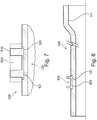
- FIG. 7 An exemplary representation of a section of the joining region 120 of a cylinder tube 500 according to the invention can be the FIG. 7 be removed.
- a joining part 300 is arranged in a form-fitting manner within an annular groove or circumferential receptacle 121 of the cylinder tube 500 and frictionally surrounds the cylinder tube 500, in particular the joining region 120. Due to the cold-formed, positive or non-positive, in particular positive and non-positive connection, the joint connection is made so strong that the cylinder tube 500 having the thick wall section 510 has the same manner as a cylinder tube made of a solid material, in particular a compressed thick wall section can be processed and / or further processed.
- the thick-wall section 510 is formed by machining material, in particular by means of turning, with a receiving groove 520, preferably for receiving a sealing ring.
- the original geometric shape of the thick wall portion 510 before the receiving groove 520 has been formed is schematically indicated by the dashed line.
Landscapes
- Engineering & Computer Science (AREA)
- Mechanical Engineering (AREA)
- Fluid-Damping Devices (AREA)
Priority Applications (1)
| Application Number | Priority Date | Filing Date | Title |
|---|---|---|---|
| EP18174630.6A EP3575014A1 (fr) | 2018-05-28 | 2018-05-28 | Tube cylindrique pour amortisseur et son procédé de fabrication |
Applications Claiming Priority (1)
| Application Number | Priority Date | Filing Date | Title |
|---|---|---|---|
| EP18174630.6A EP3575014A1 (fr) | 2018-05-28 | 2018-05-28 | Tube cylindrique pour amortisseur et son procédé de fabrication |
Publications (1)
| Publication Number | Publication Date |
|---|---|
| EP3575014A1 true EP3575014A1 (fr) | 2019-12-04 |
Family
ID=62492420
Family Applications (1)
| Application Number | Title | Priority Date | Filing Date |
|---|---|---|---|
| EP18174630.6A Withdrawn EP3575014A1 (fr) | 2018-05-28 | 2018-05-28 | Tube cylindrique pour amortisseur et son procédé de fabrication |
Country Status (1)
| Country | Link |
|---|---|
| EP (1) | EP3575014A1 (fr) |
Citations (8)
| Publication number | Priority date | Publication date | Assignee | Title |
|---|---|---|---|---|
| DE3721915A1 (de) | 1986-07-03 | 1988-01-28 | Toyota Motor Co Ltd | Zweirohr-stossdaempfer |
| DE19957508C1 (de) | 1999-11-30 | 2001-01-04 | Daimler Chrysler Ag | Vorrichtung zum Fügen von Fügeteilen auf Hohlprofile mittels fluidischen Innenhochdruckes |
| EP0944443B1 (fr) | 1996-12-13 | 2001-03-28 | MANNESMANN Aktiengesellschaft | Procede de production de tubes plaques a l'interieur |
| US20040060160A1 (en) * | 2002-01-31 | 2004-04-01 | Makoto Nishimura | Method for joining rod and collar and joining die set therefor |
| DE102005062207A1 (de) | 2005-12-24 | 2007-06-28 | Mahle International Gmbh | Nockenwelle |
| DE112012002602T5 (de) * | 2011-06-23 | 2014-04-03 | Tenneco Automotive Operating Co., Inc. | Dämpferrohr-Verstärkungshülse |
| EP3213837A1 (fr) | 2016-03-03 | 2017-09-06 | SchmitterGroup AG | Tube de pare-chocs et son procédé de fabrication |
| US20180094691A1 (en) * | 2016-09-30 | 2018-04-05 | Thyssenkrupp Bilstein Gmbh | Vibration damper for a motor vehicle and a method for producing a press fit between a damper inner tube and at least one separating plate |
-
2018
- 2018-05-28 EP EP18174630.6A patent/EP3575014A1/fr not_active Withdrawn
Patent Citations (8)
| Publication number | Priority date | Publication date | Assignee | Title |
|---|---|---|---|---|
| DE3721915A1 (de) | 1986-07-03 | 1988-01-28 | Toyota Motor Co Ltd | Zweirohr-stossdaempfer |
| EP0944443B1 (fr) | 1996-12-13 | 2001-03-28 | MANNESMANN Aktiengesellschaft | Procede de production de tubes plaques a l'interieur |
| DE19957508C1 (de) | 1999-11-30 | 2001-01-04 | Daimler Chrysler Ag | Vorrichtung zum Fügen von Fügeteilen auf Hohlprofile mittels fluidischen Innenhochdruckes |
| US20040060160A1 (en) * | 2002-01-31 | 2004-04-01 | Makoto Nishimura | Method for joining rod and collar and joining die set therefor |
| DE102005062207A1 (de) | 2005-12-24 | 2007-06-28 | Mahle International Gmbh | Nockenwelle |
| DE112012002602T5 (de) * | 2011-06-23 | 2014-04-03 | Tenneco Automotive Operating Co., Inc. | Dämpferrohr-Verstärkungshülse |
| EP3213837A1 (fr) | 2016-03-03 | 2017-09-06 | SchmitterGroup AG | Tube de pare-chocs et son procédé de fabrication |
| US20180094691A1 (en) * | 2016-09-30 | 2018-04-05 | Thyssenkrupp Bilstein Gmbh | Vibration damper for a motor vehicle and a method for producing a press fit between a damper inner tube and at least one separating plate |
Similar Documents
| Publication | Publication Date | Title |
|---|---|---|
| EP0787047B1 (fr) | Procede permettant de refouler des extremites tubulaires et dispositif de mise en uvre dudit procede | |
| DE4301124C2 (de) | Verfahren zum Verbinden einer Zylinderbuchse mit einem Grundkörper | |
| DE112019005271T5 (de) | Dämpfer mit zweiteiliger Schale | |
| EP2829353B1 (fr) | Procédé de fabrication d'un arbre à cames assemblé et dispositif correspondant | |
| EP0328007B1 (fr) | Arbre de transmission assemblé | |
| DE10135588B4 (de) | Lagerring | |
| WO2014082666A1 (fr) | Tube cylindrique (2) étanche aux fluides du côté frontal et procédé pour le fabriquer | |
| WO2003093654A1 (fr) | Came monobloc, son procede de fabrication, et assemblage d'un arbre de commande ou arbre a came | |
| EP2205371B1 (fr) | Procédé pour fabriquer des systèmes à double tube | |
| EP3213837A1 (fr) | Tube de pare-chocs et son procédé de fabrication | |
| EP3575014A1 (fr) | Tube cylindrique pour amortisseur et son procédé de fabrication | |
| DE69322945T2 (de) | Verfahren und Vorrichtung zum Fixieren eines mit zumindest einer zylindrischen Bohrung versehenen metallischen Stückes um ein metallisches Rohr | |
| DE102010004204B4 (de) | Verfahren zur Herstellung einer Nut an einem Lagergehäuse sowie gemäß dem Verfahren hergestelltes Lagergehäuse und Federbeinstützlger mit dem erfindungsgemäßen Lagergehäuse | |
| DE4334230A1 (de) | Verfahren zum Befestigen eines Profilteils in einem das Profilteil umgreifenden Hohlprofil | |
| EP1611973B1 (fr) | Procédé de formage de tubes et de fabrication d'arbres creux | |
| EP3441633B1 (fr) | Joint pivotant | |
| DE202022100872U1 (de) | Vorrichtung zum Herstellen einer einteiligen Hohlwelle aus einem rohrförmigen Werkstück aus Metall, damit herstellbare oder hergestellte Hohlwelle und Verwendung der Vorrichtung | |
| EP0986449B1 (fr) | Procede de production d'un reservoir a membrane | |
| DE102010026760A1 (de) | Verfahren zum Herstellen einer Welle | |
| DE10151659B4 (de) | Verfahren zum Fügen von zumindest zwei Bauteilen und Vorrichtung hierfür | |
| DE102011001279A1 (de) | Metallisches balgartiges Dichtungselement und Verfahren zum Herstellen des Dichtelementes | |
| DE102020104529A1 (de) | Vorrichtung und Verfahren zum mechanischen Fügen von Hohlprofilen | |
| DE102006034865B4 (de) | Verfahren zum Verbinden einer Flanschplatte mit einem abgasführenden Rohr und Flansch-Rohr-Verbindung | |
| EP1857343B1 (fr) | Tampon pour véhicules sur rail | |
| DE10135515A1 (de) | Umformwerkzeug |
Legal Events
| Date | Code | Title | Description |
|---|---|---|---|
| PUAI | Public reference made under article 153(3) epc to a published international application that has entered the european phase |
Free format text: ORIGINAL CODE: 0009012 |
|
| AK | Designated contracting states |
Kind code of ref document: A1 Designated state(s): AL AT BE BG CH CY CZ DE DK EE ES FI FR GB GR HR HU IE IS IT LI LT LU LV MC MK MT NL NO PL PT RO RS SE SI SK SM TR |
|
| AX | Request for extension of the european patent |
Extension state: BA ME |
|
| STAA | Information on the status of an ep patent application or granted ep patent |
Free format text: STATUS: THE APPLICATION IS DEEMED TO BE WITHDRAWN |
|
| 18D | Application deemed to be withdrawn |
Effective date: 20200605 |