EP3575104A1 - Zur selbstverriegelung nach herausdrücken der führung fähiges korrekturband - Google Patents
Zur selbstverriegelung nach herausdrücken der führung fähiges korrekturband Download PDFInfo
- Publication number
- EP3575104A1 EP3575104A1 EP17893688.6A EP17893688A EP3575104A1 EP 3575104 A1 EP3575104 A1 EP 3575104A1 EP 17893688 A EP17893688 A EP 17893688A EP 3575104 A1 EP3575104 A1 EP 3575104A1
- Authority
- EP
- European Patent Office
- Prior art keywords
- slot
- slider
- tape
- guiding
- position limiting
- Prior art date
- Legal status (The legal status is an assumption and is not a legal conclusion. Google has not performed a legal analysis and makes no representation as to the accuracy of the status listed.)
- Withdrawn
Links
- 238000012937 correction Methods 0.000 title claims abstract description 50
- 230000033001 locomotion Effects 0.000 claims abstract description 35
- 238000005096 rolling process Methods 0.000 claims description 17
- 230000005540 biological transmission Effects 0.000 claims description 16
- 150000001875 compounds Chemical class 0.000 claims description 15
- 238000004891 communication Methods 0.000 claims description 12
- 239000002131 composite material Substances 0.000 abstract 1
- 230000000717 retained effect Effects 0.000 abstract 1
- 230000001681 protective effect Effects 0.000 description 3
- 230000009286 beneficial effect Effects 0.000 description 1
- 230000007547 defect Effects 0.000 description 1
- 238000013461 design Methods 0.000 description 1
- 238000000034 method Methods 0.000 description 1
- 238000012986 modification Methods 0.000 description 1
- 230000004048 modification Effects 0.000 description 1
- 230000002265 prevention Effects 0.000 description 1
- 238000011160 research Methods 0.000 description 1
Images




Classifications
-
- B—PERFORMING OPERATIONS; TRANSPORTING
- B65—CONVEYING; PACKING; STORING; HANDLING THIN OR FILAMENTARY MATERIAL
- B65H—HANDLING THIN OR FILAMENTARY MATERIAL, e.g. SHEETS, WEBS, CABLES
- B65H37/00—Article or web delivery apparatus incorporating devices for performing specified auxiliary operations
- B65H37/002—Web delivery apparatus, the web serving as support for articles, material or another web
- B65H37/005—Hand-held apparatus
- B65H37/007—Applicators for applying coatings, e.g. correction, colour or adhesive coatings
-
- B—PERFORMING OPERATIONS; TRANSPORTING
- B43—WRITING OR DRAWING IMPLEMENTS; BUREAU ACCESSORIES
- B43L—ARTICLES FOR WRITING OR DRAWING UPON; WRITING OR DRAWING AIDS; ACCESSORIES FOR WRITING OR DRAWING
- B43L19/00—Erasers, rubbers, or erasing devices; Holders therefor
-
- B—PERFORMING OPERATIONS; TRANSPORTING
- B65—CONVEYING; PACKING; STORING; HANDLING THIN OR FILAMENTARY MATERIAL
- B65H—HANDLING THIN OR FILAMENTARY MATERIAL, e.g. SHEETS, WEBS, CABLES
- B65H2402/00—Constructional details of the handling apparatus
- B65H2402/60—Coupling, adapter or locking means
Definitions
- the present invention relates to a kind of correction tape, and more specifically relates to a kind that has a self-locking mechanism, wherein the correction tape has a tape guide capable of self-locking after being pushed out.
- correction tape is a kind of indispensable commodity in offices and schools.
- a correction tape commonly available nowadays is usually provided with a protective cap to protect the tape guide.
- the protective cap is removed during use, and is capped again to the tape guide when the correction tape is not in use.
- This structural design has some disadvantages: on one hand, the cap has to be removed and then capped again to the tape guide repeatedly, thus causing trouble during use; on the other hand, the removed cap may easily get lost during use, and thus often causing problems such as damages of the tape guide in the absence of protection by the cap, which in turns causing defects or pre-matured end of service life of the entire correction tape.
- the market has provided a kind of correction tape having a retractable tape guide.
- the tape guide can be extended or retracted by the cooperation between an inclined position limiting arm and a retract-positioning groove and an extend-positioning groove.
- the a great force is required to "force" a free end portion of the inclined position limiting arm to slide out of the extend-positioning groove.
- Another kind of retractable type of correction tape is also provided which may easily achieve extension and retraction of the tape guide, however, the tape guide is susceptible to outer impact that will push back the tape guide inside the correction tape when the tape guide is pushed out during use, thereby affecting the use of the correction tape.
- the present invention is conceived after thorough researches in view of the problems now existing in the currently available correction tape having a retractable tape guide.
- Correction tape with a protective cap for the tape guide requires the cap to be opened and closed repeatedly during use, therefore such correction tape is not convenient to operate and the cap is susceptible to get lost, and further, the tape guide may be easily damaged.
- Correction tape with a retractable tape guide has such retractable tape guide susceptible to be pushed back into the correction tape during use due to outer impact, thereby affecting the use of the correction tape.
- An object of the present invention is to provide a correction tape having a tape guide capable of self-locking after being pushed out. In other words, when the tape guide is pushed out and when the tape is applied, the tape guide will not be pushed back into the correction tape due to pressure on the tape guide.
- a correction tape having a tape guide capable of self-locking after being pushed out comprising a main body; the main body comprises a housing, a tape, a rolling application mechanism, a control element and a movable element; the movable element comprises the tape guide; the tape and the rolling application mechanism are provided inside the housing; the tape extends across a frontal part of the tape guide and winds around the rolling application mechanism; the control element controls movement of the movable element; a position limiting slot is provided on the movable element at an end of the movable element distal from the tape guide; the housing is provided with a guiding slot corresponding to the position limiting slot; the control element comprises a motion transmission element; the motion transmission element comprises a first slider 41 passing through firstly the guiding slot and then the position limiting slot, or comprises a second slider inserted into the guiding slot, a third slider inserted into the position limiting slot, and a triangular sliding piece; the second slider and the
- the position limiting slot and the guiding slot are each being a straight slot, a curved slot or a compound slot; the compound slot is a combination of slot sections in communication with one another; the slot sections include at least two different shapes.
- the retraction end is positioned at a side of the guiding slot near to the tape guide, and the extension end is positioned at a side of the guiding slot distal from the tape guide;
- the position limiting slot is a compound slot
- the compound slot comprises a first slot section and a second slot section in communication with one another, wherein the first slot section is a first inclined straight slot; the second slot second is a vertical straight slot or a second inclined straight slot, the stop end is provided in the first slot, and the stop end is a closed end for stopping and position limiting; a range of movement allowed in the guiding slot corresponds to a range of movement between the completely extended position and completely retracted position of the tape guide.
- a positioning protrusion is provided respectively on a side wall of the guiding slot at a position near to the extension end and/or at a position near to the retraction end.
- the control element also comprises an operating portion; the operating portion is fixedly connected with the first slider or the second slider.
- the operating portion is a rotary knob; the rotary knob has a shape of a circular cap; one end of the first slider or one end of the second slider is connected to an inner side wall of the rotary knob at a position proximal to a periphery thereof; or when the operating portion is an adjustment rod, one end of the adjustment rod is connected to said one end of the first slider or said one end of the second slider, another end of the adjustment rod is rotatably connected with the body; or when the operating portion is a push button connected with the first slider or the second slider, a diameter of the push button is larger than a slot width of the guiding slot; two opposite side walls of the push button are supported at slot walls of the guiding slot.
- the position limiting slot When the position limiting slot is a compound slot, the position limiting slot comprises a first slot section, a second slot section and a third slot section arranged in sequence and in communication with one another; the first slot section is a horizontal straight slot; the second slot section is a second inclined straight slot, and the third slot section is a vertical straight slot; the stop end is provided in the first slot section, and the initial end is provided in the third slot section.
- an arc defined by the guiding slot has a central angle greater than or equal to 90 degrees.
- the movable element is an elongated flattened piece, and is mounted inside the housing; with reference to a central axis along a lengthwise direction of the movable element after the correction tape is placed vertically where a lengthwise direction of the correction tape is parallel to a level ground, the position limiting slot is a vertical straight slot, and the stop end provided in this vertical straight slot coincides or is positioned higher than a horizontal level defined by the central axis, and the retraction end of the guiding slot correspondingly coincides or is positioned higher than the horizontal level defined by the central axis; a positioning protrusion is provided on a side wall of the position limiting slot at a position near to the stop end.
- the guiding slot When the guiding slot is a compound slot, the guiding slot comprises a first guiding slot section and a second guiding slot section in communication with each other; the first guiding slot section is a first straight slot, the second guiding slot section is a second straight slot; an included angle is formed between the first guiding slot section and the second guiding slot section.
- the control element When the guiding slot is a horizontal straight slot, the control element also comprises a push button being the operating portion; the triangular sliding piece comprises a first end, a second end and a third end; the first end is rotatably connected with an end of the movable element distal from the tape guide; the third slider is fixed connected to the second end; the triangular sliding piece is provided with an intermediate slot; one end of the intermediate slot is oriented towards the first end, and another end of the intermediate slot is oriented towards a direction which is biased with respect to a line connecting the first end and the second end; the second slider is inserted firstly into the guiding slot and then into the intermediate slot.
- the triangular sliding piece comprises a first end, a second end and a third end; the first end is rotatably connected with an end of the movable element distal from the tape guide; the third slider is fixed connected to the second end; the triangular sliding piece is provided with an intermediate slot; one end of the intermediate slot is oriented towards the first end, and
- a correction tape having a tape guide capable of self-locking after being pushed out comprising a main body; the main body comprises a housing, a tape, a rolling application mechanism, a control element and a movable element; the movable element comprises the tape guide; the tape and the rolling application mechanism are provided inside the housing; the tape extends across a frontal part of the tape guide and winds around the rolling application mechanism; the control element controls movement of the movable element; the control element comprises a fourth slider and an operating portion; a position limiting slot is provided at an end of the movable element distal from the tape guide; the housing is provided with a through hole corresponding to the position limiting slot; the through hole is mounted thereon a middle fitting body adapted to fit on the through hole; the fourth slider is connected to the middle fitting body at a position near a periphery of the middle fitting body; the operating portion and the middle fitting body are mounted together; the fourth slider is inserted into the position limiting slot.
- Two ends of the position limiting slot are an initial end and a stop end respectively; when the fourth slider is positioned at the initial end, the tape guide is completely retracted into the housing; when the fourth slider is positioned at the stop end, the tape guide is completely extended out of the housing.
- the present invention during use has the first slider, third slider or fourth slider limited within the position limiting slot; by means of outer driving force, the movable element is driven to move, thereby achieving extension or retraction of the tape guide.
- extension or retraction of the tape guide according to the present invention can be performed quickly and conveniently.
- the tape guide is completed extended out during use, while the first slider is being limited at the stop end of the position limiting slot, so during application of the tape, the stop end creates a locking force that prevents the tape guide from retracting back.
- positioning protrusion(s) provided at side walls of the guiding slot or the position limiting slot reinforce the prevention of the first slider from moving back from the stop end back to the initial end (i.e. moving back from the retraction end to the extension end in the guiding slot) which leads to retraction of the tape guide affecting the application of the tape.
- the motion transmission element is provided to achieve extension and retraction of the tape guide by making use of motion transmission provided by leverage mechanism of the triangular configuration of components.
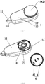
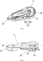
- FIGs. 1-4 A correction tape having a tape guide capable of self-locking after being pushed out is shown in FIGs. 1-4 , comprising a main body; the main body comprises a housing 1, a tape 2, a rolling application mechanism 3, a control element 4 and a movable element 5; the movable element 5 comprises a tape guide 51; the tape 2 and the rolling application mechanism 3 are provided inside the housing 1; the tape 2 extends across a frontal part of the tape guide 51 and winds around the rolling application mechanism 3; the control element 4 controls movement of the movable element 5, and in turns controls extension and retraction of the tape guide 51.
- the tape 2 and the rolling application mechanism 3 are prior arts and will not be described in detail herein.
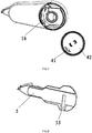
- the control element 4 comprises a first slider 41 and an operating portion; the first slider 41 has a cylindrical shape and is a motion transmission element.
- the operating portion is a rotary knob 42; the rotary knob 42 has a shape of a circular cap; the first slider 41 has a fixed end and a free end; the fixed end of the first slider is attached to the rotary knob 42 at a position proximal to a periphery thereof; the housing 1 has an elongated shape; one end of the housing 1 along a lengthwise direction thereof is provided with a tape guide opening 11; the housing 1 comprises a first housing section 12 and a second housing section 13 engageable with each other by the cooperation between grooves and protrusions; the rotary knob 42 is rotatably connected with the first housing section 12 at an end thereof distal from the tape guide opening 11; the rotary knob 42 is provide with anti-slip textured patterns along the periphery thereof to facilitate rotation.
- the movable element 5 is an elongated flattened piece, mounted in between the first housing section 12 and the second housing section 13; the movable element 5 comprises a tape guide end and a drive end 52; the drive end 52 is provided with a position limiting slot 53 at a side wall thereof corresponding to the first housing section 12.
- a central axis 54 along a lengthwise direction of the movable element 5 after the correction tape is placed vertically where the lengthwise direction of the correction tape is parallel to a horizontal level it is observed that the tape guide is positioned at a left side, the drive end 52 is positioned at a right side, the first slider 41 is positioned at a bottom side of the central axis 54, and an opposite side with respect to the bottom side of the central axis is an upper side.
- Directions as will be described below will be referenced according to the directional references as indicated above.
- the position limiting slot 53 is positioned at a right side of the movable element 5. Also, the position limiting slot 53 is positioned within the bottom zone.
- the position limiting slot 53 is a compound slot comprising a first slot section 531 and a second slot section 532 in communication with each other.
- the first slot section 531 is provided at a side more near to the tape guide 51
- the second slot section 532 is provided at a side more distal from the tape guide 51, in other words, the first slot section 531 is positioned at a left side of the second slot section 532.
- the first slot section 531 and the second slot section 532 are in communication with each other, and both have equal depths.
- the first slot section 531 is a first inclined straight slot that inclines leftward.
- the second slot section 532 is a vertical straight slot. Both the first slot section 531 and the second slot section 532 have widths corresponding to a diameter of the first slider 41.
- the first slot section 531 has a stop end, and this stop end is a closed end for stopping and position limiting.
- the second slot section 532 has an initial end. The stop end is positioned higher than the initial end, in other words, the initial end is located above the initial end.
- the stop end of the position limiting slot 53 is a round end preferably corresponding to the cylindrical shape of the first slider 41.
- a right side of the first housing section 12 is provided with a guiding slot 16 corresponding to the position limiting slot 53.
- the guiding slot 16 is a curved slot comprising an extension end and a retraction end; the retraction end is positioned higher than the extension end, in other words, the retraction end is positioned above the extension end.
- the guiding slot 16 is positioned at the bottom zone with respect to the central axis 54, in other words, both the extension end and the retraction end of the guiding slot 16 are positioned within the bottom zone with respect to the central axis 54.
- An arc of the guiding slot 16 (i.e. the curved slot) has a central angle less than 90 degrees.
- a range of movement allowed in the guiding slot 16 corresponds to a range of movement between the completely extended position and completely retracted position of the tape guide 51.
- a positioning protrusion 14 is provided respectively on a side wall of the guiding slot 16 at a position near to the extension end and at a position near to the retraction end.
- the positioning protrusion 14 is made of plastic material and is slightly resilient.
- the first slider 41 passes through firstly the guiding slot 16 and then the position limiting slot 53; by means of the guiding function of the guiding slot 16 and through the cooperation with the position limiting slot, the first slider 41 drives the movable element 5 to move and thus achieves extension and retraction of the tape guide 51.
- the first slider 41 is positioned or movable within the position limiting slot 53.
- the first slider 41 slides from the second slot section 532 to the first slot section 531, while there is no corresponding change of position between the movable element 5 and the guiding slot 16. Finally, the first slider 41 is positioned at the retraction end of the guiding slot 16, whereas the positioning protrusion 14 near to the retraction end prevents the first slider 41 from sliding downwardly driving the rotary knob 42 to rotate anti-clockwise.
- the movable element 5 When applying the tape during use, the movable element 5 is subject to a rightward horizontal pressure force F1; during application of the tape, the first slider 41 contacts and presses against a wall of the first slot section 531 of the position limiting slot 53, wherein a contact surface between the first slider and the wall of the first slot section is an inclined surface or a curved surface at the round end of the closed end, therefore the contact surface is influenced by the inclination of the inclined straight slot (i.e. the first slot section 531), accordingly, the first slider 41 is subject to resilient force F2.
- F2 When the contact surface is an inclined surface, F2 is perpendicular to the inclined surface; when the contact surface is a curved surface, F2 is oriented towards a center of circle of the curved surface at the round end.
- F3 is a component force of F2 along a vertical direction.
- F3 can facilitate rotation of the rotary knob 42 along the clockwise direction, however, as a wall of the retraction end of the guiding slot 16 prevents the rotary knob 42 to further rotate clockwise, F3 here is considered is a locking force.
- the movable element 5 can self-lock, thereby achieving self-locking of the tape guide 51.
- the present invention can be operated quickly and conveniently during extension and retraction of the tape guide. Also, when the tape guide 51 is completed extended, the first slider 41 is limited at the stop end of the position limiting slot 53; when applying the tape, the position limiting slot 53 has a locking force that prevents retraction of the first slider 41 during the course of applying the tape.
- embodiment 2 has the following differences compared with embodiment 1: structures of the position limiting slot 53 and structures of the operating portion.
- the position limiting slot 53 is a compound slot, which comprises in a top-down sequence a first slot section 531, a second slot section 532 and a third slot section 533.
- the first slot section 531, the second slot section 532 and the third slot section 533 are in communication with one another, and all of them have equal depths.
- the first slot section 531 is a horizontal straight slot;
- the second slot section 532 is a second inclined straight slot inclined to left side;
- the third slot section 533 is a vertical straight slot;
- a stop end of the first slot section 531 is a closed end which can achieve stopping and position limiting.
- the operating portion is an adjustment rod; one end of the adjustment rod is connected to the fixed end of the first slider 41; another end of the adjustment rod is rotatably connected to a supporting point on the first housing section 12.
- the supporting point is a center of circle of an arc defined by the curved slot (i.e. the guiding slot 16).
- the highest point of the first slot section 531 is a closed end for stopping and position limiting.
- the first slider 41 has a cylindrical shape.
- the closed end of the position limiting slot 53 is a round end preferably corresponding to the cylindrical shape of the first slider 41.
- the first slider 41 When applying the tape, the first slider 41 is limited in the first slot section 531 (the horizontal straight slot) of the position limiting slot 53, and the movable element is subject to a rightward horizontal pressure force F1; during application of the tape, the first slider 41 contacts and presses against a wall of the first slot section 531 of the position limiting slot 53, wherein a contact surface between the first slider and the wall of the first slot section is a curved surface at the round end of the closed end, accordingly, the first slider 41 is subject to resilient force F2, which is oriented towards a center of circle of the curved surface at the round end.
- F3 is a component force of F2 along a vertical direction.
- F3 can facilitate rotation of the adjustment rod 43 along the clockwise direction, however, as a wall of the retraction end of the guiding slot 16 prevents the rotary knob 42 to further rotate clockwise, F3 here is considered is a locking force.
- the resilience force of F2 is oriented more closely to a vertical direction than the resilience force F2 in embodiment 1. Therefore, the resilient force F2 has a greater component force F3 along the vertical direction, meaning a greater locking force.
- the positioning slot 53 is provided with an inclined straight slot by means of which self-locking can be achieved.
- the self-locking as achieved is more secured.
- embodiment 3 has the following differences compared with embodiment 1: structures of the position limiting slot 53 and structures of the guiding slot 16.
- the position limiting slot 53 is a straight slot, in particular, a vertical straight slot; a positioning protrusion 14 is provided at a side wall of the vertical straight slot near to the stop end of the vertical straight slot.
- the stop end of the vertical slot extends from the bottom zone of the movable element 5 up to the upper zone of the movable element 5.
- the guiding slot is a curved slot; an arc defined by the curved slot has a central angle less than 90 degrees; also, the retraction end of the guiding slot 16 extends to the upper zone of the movable element 5; the initial end of the vertical straight slot is provided within the bottom zone of the movable element 5.
- the first slider 41 When applying the tape, the first slider 41 is limited at the stop end of the vertical straight slot, such that a circumferential force F3 facilitating the rotary knob 42 to rotate clockwise is created during application of the tape.
- F3 is considered a locking force.
- the central angle of an arc defined by the curved slot can also be equal to 90 degrees.
- embodiment 4 has the following differences compared to embodiment 1: structures of the guiding slot 16 and structures of the operating portion.
- the guiding slot is a compound slot, comprising a first guiding slot section 161 and a second guiding slot section 162 in communication with each other.
- the first guiding slot section 161 is an inclined straight slot (a first straight slot)
- the second guiding slot section 162 is a horizontal straight slot (a second straight slot); an included angle is formed between the first guiding slot section 161 and the second guiding slot section 162.
- a range of movement allowed in the horizontal straight slot corresponds to a range of movement between the completely extended position and completely retracted position of the tape guide 51.
- the operating portion is a push button 44.
- the push button 44 is connected with the fixed end of the first slider 41; a diameter of the push button 44 is larger than a slot width of the guiding slot 16; two opposite side walls of the push button 44 are supported at slot walls of the guiding slot 16.
- a positioning protrusion for position limiting may be provided on the guiding slot 16 at a position near the extension end or at a position near the retraction end.
- embodiment 5 has the following differences compared with embodiment 4: structures of the guiding slot, structures of the control element 4 and structures of the position limiting slot 53.
- the guiding slot 16 is a horizontal straight slot; the position limiting slot 53 is an inclined straight slot inclined to the left.
- the stop end of the inclined straight slot extends from the bottom zone of the movable element 5 to the upper zone of the movable element 5.
- the initial end of the inclined straight slot is positioned within the bottom zone of the movable element 5.
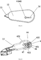
- the control element 4 comprises a push button 44 and a motion transmission element. A portion of the drive end 52 the movable element 5 near a right periphery of the drive end 52 is provided with a trough for movement of the motion transmission element.
- the motion transmission element comprises a triangular sliding piece 45, a second slider 46, and a third slider 47.
- the push button 44 is fixedly connected with one end of the second slider 46;
- the triangular sliding piece 45 has a triangular shape and comprises a first end 455, a second end 452 and a third end 453.
- the triangular sliding piece 45 is rotatably connected with the movable element 5 via the first end 455, and is limited in the trough.
- the third slider 47 has a fixed end and a free end; a fixed end of the third slider 47 is connected with the second end 452.
- the triangular sliding piece 45 is also provided with an inclined intermediate slot 451; one end of the intermediate slot 451 is oriented towards the first end 455, and another end of the intermediate slot 451 is oriented towards a direction which is biased with respect to a line connecting the first end 455 and the second end 452, in other words, the intermediate slot 451 does not coincide with the line connecting the first end 455 and the second end 452.
- said another end of the intermediate slot 451 is oriented to the third end 453.
- the second slider 46 is inserted firstly into the guiding slot 16 and then into the intermediate slot 451; the free end of the third slider 47 is inserted into the position limiting slot 53.
- the second slider 46 move within the trough under the guiding function of the guiding slot 16; movement of the second slider 46 in the trough drives the triangular sliding piece 45 to move, which in turns drives the third slider 47 to slide within the position limiting slot 53; movement of the third slider 47 drives the movable element 5 to move, thereby achieving extension and retraction of the tape guide 51.
- leverage mechanism of the triangular sliding piece 45 is employed for achieving extension and retraction of the tape guide 51.
- embodiment 6 has the following differences compared with embodiment 3: structures of the rotary knob 42, structures of the position limiting slot 53 and structures of the first housing section 12.
- the guiding slot is not provided.
- a fourth slider 48 as will be described below is equivalent to the first slider 41 described in embodiment 3.
- the first housing section 12 is provided with a through hole 15 corresponding to the position limiting slot 53; the through hole is mounted thereon a middle fitting body; the middle fitting body 17 is adapted to fit on the through hole 15 so as to seal the through hole 15.
- the rotary knob 42 is a circular cap.
- the rotary knob 42 and the middle fitting body 17 are fitted together by means of fastening mechanism.
- a fixed end of the fourth slider 48 is connected to the middle fitting body 17 at a position near a periphery of the middle fitting body 17.
- the position limiting slot 53 is a vertical straight slot; a positioning protrusion 14 is provided at a stop end of the vertical straight slot.
- rotation of the rotary knob 42 drives the rotation of the middle fitting body 17 and the fourth slider 48; the fourth slider 48 is limited within the position limiting slot 53; the fourth slider 48 drives the movable element 5 to move.
- the analysis regarding the locking force, and regarding the movements of the first slider 41, the second slider 46, the third slider 47 and the fourth slider 48 can be obtained basic knowledge of physics known to a person skilled in the art, therefore, these analysis are omitted in some embodiments described above.
- the movable element and the tape guide can be connected integrally, or can be connected by means of fastening components.
Landscapes
- Closures For Containers (AREA)
- Supply And Installment Of Electrical Components (AREA)
- Packaging Of Annular Or Rod-Shaped Articles, Wearing Apparel, Cassettes, Or The Like (AREA)
- Printers Characterized By Their Purpose (AREA)
Applications Claiming Priority (2)
| Application Number | Priority Date | Filing Date | Title |
|---|---|---|---|
| CN201720104447.2U CN206968252U (zh) | 2017-01-24 | 2017-01-24 | 一种推咀后能自锁的修正带 |
| PCT/CN2017/115531 WO2018137416A1 (zh) | 2017-01-24 | 2017-12-12 | 一种推咀后能自锁的修正带 |
Publications (2)
| Publication Number | Publication Date |
|---|---|
| EP3575104A1 true EP3575104A1 (de) | 2019-12-04 |
| EP3575104A4 EP3575104A4 (de) | 2020-11-11 |
Family
ID=61414729
Family Applications (1)
| Application Number | Title | Priority Date | Filing Date |
|---|---|---|---|
| EP17893688.6A Withdrawn EP3575104A4 (de) | 2017-01-24 | 2017-12-12 | Zur selbstverriegelung nach herausdrücken der führung fähiges korrekturband |
Country Status (4)
| Country | Link |
|---|---|
| EP (1) | EP3575104A4 (de) |
| JP (1) | JP3222384U (de) |
| CN (1) | CN206968252U (de) |
| WO (1) | WO2018137416A1 (de) |
Cited By (1)
| Publication number | Priority date | Publication date | Assignee | Title |
|---|---|---|---|---|
| CN112046178A (zh) * | 2020-10-21 | 2020-12-08 | 广东乐普升文具有限公司 | 一种笔形修正带 |
Families Citing this family (3)
| Publication number | Priority date | Publication date | Assignee | Title |
|---|---|---|---|---|
| CN106585226B (zh) * | 2017-01-24 | 2019-02-15 | 泉州市一扬文化用品有限公司 | 一种推咀后能自锁的修正带 |
| CN113400845B (zh) * | 2021-08-12 | 2025-02-11 | 泉州市天高文化用品有限公司 | 一种推咀自动解锁的卷绕式文具 |
| TWI877840B (zh) * | 2023-10-13 | 2025-03-21 | 昶邑國際有限公司 | 便於換帶之薄膜塗抹器推鈕結構改良 |
Family Cites Families (11)
| Publication number | Priority date | Publication date | Assignee | Title |
|---|---|---|---|---|
| JP3039407B2 (ja) * | 1996-12-27 | 2000-05-08 | コクヨ株式会社 | 転着テープヘッドの保護カバー |
| JP4316771B2 (ja) * | 2000-05-09 | 2009-08-19 | 株式会社トンボ鉛筆 | 塗膜転写具 |
| CN2538755Y (zh) * | 2002-04-10 | 2003-03-05 | 宁海县小雪人文具有限公司 | 可防带芯倒转的修正带盒 |
| TWI403424B (zh) * | 2010-10-21 | 2013-08-01 | Sdi Corp | A push-button-locked film transponder |
| TWI547386B (zh) * | 2012-01-20 | 2016-09-01 | Sdi Corp | A band with a locking function, and a film transducer with the core band |
| CN204687662U (zh) * | 2015-05-21 | 2015-10-07 | 泉州市一扬文化用品有限公司 | 一种伸缩笔型修正带 |
| CN105059024B (zh) * | 2015-08-10 | 2017-04-26 | 泉州市一扬文化用品有限公司 | 一种弹簧按压式笔型修正带 |
| CN204870241U (zh) * | 2015-08-31 | 2015-12-16 | 章承光 | 一种可伸缩的活动压嘴的修正带 |
| CN105197662B (zh) * | 2015-09-06 | 2017-03-22 | 广东乐普升文具有限公司 | 一种供卷带的功能薄膜转帖并将基带回收的卷绕式装置 |
| CN205292051U (zh) * | 2015-12-25 | 2016-06-08 | 陈明雄 | 带有自锁装置的伸缩修正带 |
| CN106585226B (zh) * | 2017-01-24 | 2019-02-15 | 泉州市一扬文化用品有限公司 | 一种推咀后能自锁的修正带 |
-
2017
- 2017-01-24 CN CN201720104447.2U patent/CN206968252U/zh not_active Withdrawn - After Issue
- 2017-12-12 EP EP17893688.6A patent/EP3575104A4/de not_active Withdrawn
- 2017-12-12 WO PCT/CN2017/115531 patent/WO2018137416A1/zh not_active Ceased
- 2017-12-12 JP JP2019600013U patent/JP3222384U/ja active Active
Cited By (1)
| Publication number | Priority date | Publication date | Assignee | Title |
|---|---|---|---|---|
| CN112046178A (zh) * | 2020-10-21 | 2020-12-08 | 广东乐普升文具有限公司 | 一种笔形修正带 |
Also Published As
| Publication number | Publication date |
|---|---|
| EP3575104A4 (de) | 2020-11-11 |
| JP3222384U (ja) | 2019-08-01 |
| WO2018137416A1 (zh) | 2018-08-02 |
| CN206968252U (zh) | 2018-02-06 |
Similar Documents
| Publication | Publication Date | Title |
|---|---|---|
| US7438112B2 (en) | Roll-up barrier | |
| US9260914B2 (en) | Covering for an architectural opening | |
| US10633916B2 (en) | Window shade and actuating system thereof | |
| WO2014163666A4 (en) | Blade positioning device | |
| JP5979459B2 (ja) | 出没式筆記具のプッシュロック装置{pushlocksystemforslidetypewritingtools} | |
| US8061757B1 (en) | Force assist for sunshade closing slide mechanism | |
| CA2529547A1 (en) | Door lock assembly having a press button in an inner handle | |
| CN209190828U (zh) | 毛发切削设备 | |
| CN108301683B (zh) | 用于门或窗的手柄 | |
| US20250249701A1 (en) | Push-action compass | |
| JP3222384U (ja) | プッシュアウトした後にセルフロッキングできる修正テープ | |
| JP5173222B2 (ja) | 引戸用クローザ装置 | |
| KR20160063388A (ko) | 회전 핸들용 캡 | |
| US2409658A (en) | Cosmetic container | |
| PL2142732T3 (pl) | Zespół klucza i obudowy | |
| US9180722B2 (en) | Mechanical pencil having lead-rotating mechanism | |
| JP2014062391A (ja) | 引込み装置ユニット | |
| JP5001079B2 (ja) | 清掃具 | |
| CN204091201U (zh) | 一种自动开收伞伞头锁键装置 | |
| US4520639A (en) | Double dead bolt door lock | |
| CN218428450U (zh) | 一种旋转伸缩工具刀 | |
| KR20180124346A (ko) | 슬라이딩 창호용 그립형 잠금장치 | |
| US2773478A (en) | Cartridge projecting and retracting mechanism for ball point pens | |
| CN201887249U (zh) | 数字便携设备的隐藏式插座 | |
| CN216789359U (zh) | 一种直行程电动执行器 |
Legal Events
| Date | Code | Title | Description |
|---|---|---|---|
| STAA | Information on the status of an ep patent application or granted ep patent |
Free format text: STATUS: THE INTERNATIONAL PUBLICATION HAS BEEN MADE |
|
| PUAI | Public reference made under article 153(3) epc to a published international application that has entered the european phase |
Free format text: ORIGINAL CODE: 0009012 |
|
| STAA | Information on the status of an ep patent application or granted ep patent |
Free format text: STATUS: REQUEST FOR EXAMINATION WAS MADE |
|
| 17P | Request for examination filed |
Effective date: 20190718 |
|
| AK | Designated contracting states |
Kind code of ref document: A1 Designated state(s): AL AT BE BG CH CY CZ DE DK EE ES FI FR GB GR HR HU IE IS IT LI LT LU LV MC MK MT NL NO PL PT RO RS SE SI SK SM TR |
|
| AX | Request for extension of the european patent |
Extension state: BA ME |
|
| DAV | Request for validation of the european patent (deleted) | ||
| DAX | Request for extension of the european patent (deleted) | ||
| A4 | Supplementary search report drawn up and despatched |
Effective date: 20201009 |
|
| RIC1 | Information provided on ipc code assigned before grant |
Ipc: B43L 19/00 20060101AFI20201005BHEP Ipc: B65H 37/00 20060101ALI20201005BHEP |
|
| GRAP | Despatch of communication of intention to grant a patent |
Free format text: ORIGINAL CODE: EPIDOSNIGR1 |
|
| STAA | Information on the status of an ep patent application or granted ep patent |
Free format text: STATUS: GRANT OF PATENT IS INTENDED |
|
| INTG | Intention to grant announced |
Effective date: 20230317 |
|
| STAA | Information on the status of an ep patent application or granted ep patent |
Free format text: STATUS: THE APPLICATION IS DEEMED TO BE WITHDRAWN |
|
| 18D | Application deemed to be withdrawn |
Effective date: 20230701 |