EP3575144B1 - Dynamisches pneumatisches stützsystem - Google Patents
Dynamisches pneumatisches stützsystem Download PDFInfo
- Publication number
- EP3575144B1 EP3575144B1 EP18174781.7A EP18174781A EP3575144B1 EP 3575144 B1 EP3575144 B1 EP 3575144B1 EP 18174781 A EP18174781 A EP 18174781A EP 3575144 B1 EP3575144 B1 EP 3575144B1
- Authority
- EP
- European Patent Office
- Prior art keywords
- bladder
- back rest
- dorsal
- lumbar
- pressure
- Prior art date
- Legal status (The legal status is an assumption and is not a legal conclusion. Google has not performed a legal analysis and makes no representation as to the accuracy of the status listed.)
- Active
Links
Images

Classifications
-
- B—PERFORMING OPERATIONS; TRANSPORTING
- B60—VEHICLES IN GENERAL
- B60N—SEATS SPECIALLY ADAPTED FOR VEHICLES; VEHICLE PASSENGER ACCOMMODATION NOT OTHERWISE PROVIDED FOR
- B60N2/00—Seats specially adapted for vehicles; Arrangement or mounting of seats in vehicles
- B60N2/90—Details or parts not otherwise provided for
- B60N2/914—Hydro-pneumatic adjustments of the shape
-
- A—HUMAN NECESSITIES
- A47—FURNITURE; DOMESTIC ARTICLES OR APPLIANCES; COFFEE MILLS; SPICE MILLS; SUCTION CLEANERS IN GENERAL
- A47C—CHAIRS; SOFAS; BEDS
- A47C7/00—Parts, details, or accessories of chairs or stools
- A47C7/36—Supports for the head or the back
- A47C7/40—Supports for the head or the back for the back
- A47C7/46—Supports for the head or the back for the back with special, e.g. adjustable, lumbar region support profile; "Ackerblom" profile chairs
- A47C7/467—Supports for the head or the back for the back with special, e.g. adjustable, lumbar region support profile; "Ackerblom" profile chairs adjustable by fluid means
-
- B—PERFORMING OPERATIONS; TRANSPORTING
- B60—VEHICLES IN GENERAL
- B60N—SEATS SPECIALLY ADAPTED FOR VEHICLES; VEHICLE PASSENGER ACCOMMODATION NOT OTHERWISE PROVIDED FOR
- B60N2/00—Seats specially adapted for vehicles; Arrangement or mounting of seats in vehicles
- B60N2/02—Seats specially adapted for vehicles; Arrangement or mounting of seats in vehicles the seat or part thereof being movable, e.g. adjustable
- B60N2/0224—Non-manual adjustments, e.g. with electrical operation
- B60N2/0244—Non-manual adjustments, e.g. with electrical operation with logic circuits
- B60N2/026—Non-manual adjustments, e.g. with electrical operation with logic circuits varying hardness or support of upholstery, e.g. for tuning seat comfort when driving curved roads
-
- B—PERFORMING OPERATIONS; TRANSPORTING
- B60—VEHICLES IN GENERAL
- B60N—SEATS SPECIALLY ADAPTED FOR VEHICLES; VEHICLE PASSENGER ACCOMMODATION NOT OTHERWISE PROVIDED FOR
- B60N2/00—Seats specially adapted for vehicles; Arrangement or mounting of seats in vehicles
- B60N2/02—Seats specially adapted for vehicles; Arrangement or mounting of seats in vehicles the seat or part thereof being movable, e.g. adjustable
- B60N2/0224—Non-manual adjustments, e.g. with electrical operation
- B60N2/0244—Non-manual adjustments, e.g. with electrical operation with logic circuits
- B60N2/0268—Non-manual adjustments, e.g. with electrical operation with logic circuits using sensors or detectors for adapting the seat or seat part, e.g. to the position of an occupant
-
- B—PERFORMING OPERATIONS; TRANSPORTING
- B60—VEHICLES IN GENERAL
- B60N—SEATS SPECIALLY ADAPTED FOR VEHICLES; VEHICLE PASSENGER ACCOMMODATION NOT OTHERWISE PROVIDED FOR
- B60N2/00—Seats specially adapted for vehicles; Arrangement or mounting of seats in vehicles
- B60N2/02—Seats specially adapted for vehicles; Arrangement or mounting of seats in vehicles the seat or part thereof being movable, e.g. adjustable
- B60N2/0296—Central command actuator to selectively switch on or engage one of several special purpose circuits or mechanisms
-
- B—PERFORMING OPERATIONS; TRANSPORTING
- B60—VEHICLES IN GENERAL
- B60N—SEATS SPECIALLY ADAPTED FOR VEHICLES; VEHICLE PASSENGER ACCOMMODATION NOT OTHERWISE PROVIDED FOR
- B60N2/00—Seats specially adapted for vehicles; Arrangement or mounting of seats in vehicles
- B60N2/64—Back-rests or cushions
- B60N2/66—Lumbar supports
- B60N2/665—Lumbar supports using inflatable bladders
Definitions
- the present invention relates to a dynamic pneumatic support system for integration into a back rest of a vehicle seat.
- the invention further relates to a method of self-adjusting such a dynamic pneumatic support system as well as to a vehicle seat comprising such a dynamic pneumatic support system.
- Vehicle seats are in general well cushioned seats to provide a pleasant seating experience during travel.
- a thick cushioning increases the weight of the seat and thus of the vehicle which, in turn, demands a stronger engine and increases fuel consumption of the vehicle.
- US-A-5707109 discloses a vehicle seat comprising adjustors which are activated in response to predetermined level of acceleration forces experienced by the seat.
- inflatable support elements were integrated into vehicle seats of the prior art.
- the softness and flexibility of these support elements provided good cushioning properties. Thus, they were used as additional cushioning elements above or below a smaller common cushioning.
- the support elements were used to provide a passenger-adjusted cushioning. Thereby, the seating comfort of a passenger's seat was further improved.
- Document DE 10 2010 020 642 A1 describes a vehicle seat, in particular an aircraft passenger seat, comprising an inflatable air cushion and an inclination sensor of the back rest, wherein the pressure of the air cushion is controlled with respect to the inclination of the back rest.
- Document DE 10 2006 004 071 A1 describes a pneumatic device for a seat, in particular an aircraft passenger seat, comprising at least a second computational unit for redundancy to ensure a high comfort in particular on long-distant flights.
- Document US 9,327,625 B2 describes a vehicle seat including a seat back that is variable in shape and a control device, wherein the control device controls an introduction and discharge of air into and from each air bag based on a state of change in the air in each air bag that occurs, when the seat occupant sits, to change the shape of the seat back to a shape that conforms to the seat occupant's unique sitting position.
- Document US 8,616,654 B2 describes a method and a device for adjusting a seat, wherein the method includes the acts of detecting a pressure exerted by a user on the seat via a pneumatic sensor and/or hydraulic sensor. Thereby, a first lifting element adjusts the seat based on the pressure exerted by the user.
- a passenger-adjusted cushioning may lose its benefits or even become uncomfortable when stronger motion forces occur that force a passenger into unusual or unwanted seating positions.
- An uncomfortable seating position though, may for example distract a driver and reduce his or her attention to the driving or to the actual road traffic.
- a dynamic pneumatic support system for integration into a back rest of a vehicle seat, the dynamic pneumatic support system comprising at least one lumbar support bladder, arranged at the lumbar region of a back rest, at least one dorsal support bladder, arranged at least at a shoulder region of the back rest, a pump unit for supplying the lumbar support bladder and the dorsal support bladder individually with air, an electronic control unit for controlling the pump unit, and a sensor unit connected to the electronic control unit for automatically measuring orientation and/or acceleration of the back rest and providing orientation and/or acceleration data to the electronic control unit, wherein the electronic control unit can, based on the orientation and/or acceleration data, control the pump unit, for automatically and individually controlling the pressure of at least the lumbar support bladder and dorsal support bladder.
- the dynamic pneumatic support system of the present invention is in particularly advantageous when the passenger tilts the backrest of the seat from a driving position into a relaxing position.
- the dynamic pneumatic support system maintains the users comfort experience in any inclination of the backrest of the seat.
- Further dynamic pneumatic support system is particularly advantageous when integrated into a vehicle seat, during a tilted, i.e. inclined, motion and/or a curved motion of the vehicle. During such a motion a passenger or driver, respectively, of the vehicle is exposed to gravitational or centrifugal forces which will force the passenger away from its original and comfortable seating position to an unwanted and often uncomfortable position.
- the present dynamic pneumatic support system will provide additional support to the passenger in such situations in that the cushioning, i.e.
- the air pressure and thus the volume of the inflatable cushioning elements and bladders, respectively, is increased/decreased in the stressed regions of the seat.
- a more comfortable seating position is achieved when the passenger is supported towards its original, upright sitting, position. Therefore, the cushioning in the dorsal region is intensified.
- the pump unit may pump air into the respective bladder or may release air out of the respective bladder. This increases the pressure within the bladder or decreases the pressure within the bladder and, thus, also changes the shape and/or stroke of the respective bladder.
- the lumbar and dorsal support bladders each cushion the respective zone of the human body of a passenger. Thereby, comfort for the passenger is increased if the vehicle tilts around a transversal axis.
- the electronic control unit dynamically controls the pressure of the at least one lumbar support bladder and of the at least one dorsal support bladder, in a way that when the inclination of the back rest with respect to a vertical direction increases, e.g. when moving the back rest from a driving position to a relaxing position, the pressure of the lumbar support bladder decreases to a predetermined lumbar inclination pressure value or is maintained at a manually set pressure below this predetermined lumbar inclination pressure value, and / or the pressure of the dorsal support bladder increases to a predetermined dorsal inclination pressure value or is maintained at a manually set pressure above this predetermined dorsal inclination pressure value.
- This automatic adjustment of the lumbar and dorsal support bladders increases the comfort of the seat in relaxing position, in which the back rest is more inclined. Further, the manually set comfort pressures of the passengers are taken into consideration. No pressure change is performed, if the manually set pressure of the lumbar bladder is already below the predetermined lumbar inclination pressure value and if the manually set pressure of the dorsal bladder is already above the predetermined dorsal inclination pressure value.
- the electronic control unit dynamically controls the pressure of the at least one lumbar support bladder and of the at least one dorsal support bladder, in a way that when the inclination of the back rest with respect to a vertical direction decreases, e.g.
- the pressure of the lumbar support bladder increases to a stored manually set pressure above a predetermined lumbar inclination pressure value or is maintained at a manually set pressure below this predetermined lumbar inclination pressure value, and / or the pressure of the dorsal support bladder decreases to a stored manually set pressure above a predetermined dorsal inclination pressure value or is maintained at a manually set pressure above this predetermined dorsal inclination pressure value.
- This automatic adjustment of the lumbar and dorsal support bladders increases the comfort of the seat in driving position, in which the back rest is less inclined. Preferably, the comfort of the seat is restored as it was in driving position before the passenger chose the relaxing position of the seat.
- the electronic control unit provides the original manually set pressure values of the lumbar and dorsal support bladders.
- the electronic control unit is programmed such that, when the inclination angle of the backrest increases, the predetermined lumbar inclination pressure value decreases, and / or the predetermined dorsal inclination pressure value increases.
- the pressures of the lumbar and dorsal bladders are continuously adapted to the present inclination of the back rest. The more the back rest is inclined, the more the predetermined lumbar inclination pressure value decreases and the more the predetermined dorsal inclination pressure value increases.
- the predetermined lumbar inclination pressure value is about 40% to 85% of the manually set pressure value, preferably, the predetermined lumbar inclination pressure value is about 65% to 85% of the manually set pressure value at an back rest inclination angle of about 45°, and further preferably the predetermined lumbar inclination pressure value is about 40% to 60% of the manually set pressure value at an back rest inclination angle of about 70°.
- Such pressure values of the lumbar support bladder provide an optimized comfort of the seat in differently inclined positions.
- the predetermined dorsal inclination pressure value is about 50% to 75% of the maximum dorsal pressure value, preferably, the predetermined dorsal inclination pressure value is about 50% of the maximum dorsal pressure value at an back rest inclination angle of about 45°, and further preferably the predetermined dorsal inclination pressure value is about 75% of the maximum dorsal pressure value at an back rest inclination angle of about 70°.
- Such pressure values of the dorsal support bladder provide an optimized comfort of the seat in differently inclined positions.
- the dynamic pneumatic support system comprises two or three lumbar support bladders, the pressures of which are individually controlled by the electronic control unit.
- two or three lumbar support bladders which are preferably arranged at different height levels at the backrest the overall shape and particularly overall height position of the lumbar support can be adjusted to the passenger's needs and size.
- individually controlling the pressure in each of the lumbar support bladders the overall shape and experienced height of the lumbar support can be easily adapted without having any mechanical elements for shifting the lumbar support bladders. For example, if the highest arranged lumbar support bladder has a higher pressure than the lower arranged bladders the apex of the overall lumbar support will be at a high height level at the backrest. If the lowest arranged lumbar support bladder has a higher pressure than the higher arranged lumbar support bladders the apex of the overall lumbar support will be at a low height level at the backrest.
- the dynamic pneumatic support system further comprises at least one right side support bladder, arranged at the right side of the back rest, and at least one left side support bladder, arranged at the left side the back rest, wherein the left and right side support bladders are individually in fluid connection with the pump unit, for supplying the right side support bladder and the left side support bladder individually with air, and the electronic control unit can, based on the orientation and/or acceleration data, control the pump unit, for automatically and individually controlling the pressure of at least the right side support bladder and the left side support bladder.
- the left and right side support bladders can provide an adequate counter force to the above-mentioned gravitational and/or centrifugal forces in order to keep the passenger in its original comfortable position.
- a dynamic pneumatic support system for integration into a back rest of a vehicle seat
- the dynamic pneumatic support system comprising at least one right side support bladder, arranged at the right side of a back rest and at least one left side support bladder, arranged at the left side of the back rest, the left and right side support bladders are individually in fluid connection with a pump unit, for supplying the right side support bladder and the left side support bladder individually with air, an electronic control unit for controlling the pump unit, a sensor unit connected to the electronic control unit for automatically measuring orientation of the dynamic pneumatic support system and/or acceleration and providing orientation and/or acceleration data to the electronic control unit, wherein the electronic control unit can, based on the orientation and/or acceleration data, control the pump unit, for automatically and individually controlling the pressure of at least the right side support bladder and the left side support bladder.
- the electronic control unit comprises two adjustment modes, wherein in a first manual adjustment mode the pressure of the bladders can be manually adjusted by the user, and wherein in a second automatic adjustment mode the pressure of the bladders is automatically adjusted by the electronic control unit.
- a first manual adjustment mode the pressure of the bladders can be manually adjusted by the user
- a second automatic adjustment mode the pressure of the bladders is automatically adjusted by the electronic control unit.
- the manual adjustment mode the user can adjust the back rest shape to his personal comfort requirements.
- the automatic adjustment mode the dynamic pneumatic support system automatically maintains the comfort appearance for the user under different driving conditions and when the backrest inclination is changed.
- the electronic control unit based on the measured orientation data and/or acceleration data, controls the pump unit for automatically controlling the pressure of the bladders for counteracting the acceleration and/or the gravity.
- the pressure in the bladders is controlled according the acceleration, preferably lateral acceleration when driving a curve, and / or gravity when driving a slope or when the backrest inclination is changed.
- the sensor unit comprises a 3-axis sensor and/or an acceleration sensor or wherein the electronic control unit can receive acceleration data from external sources instead of the acceleration sensor.
- the dynamic pneumatic support system maintains the users comfort experience in any inclination of the backrest of the seat and during a tilted, i.e. inclined, motion and/or a curved motion of the vehicle.
- the method of self-adjusting a dynamic pneumatic support system further comprising the following steps:
- the automatic controlling step comprises the steps of increasing the pressure in one of the bladders and at the same time decreasing the pressure of the corresponding other bladder.
- the automatic adjustment of the bladders can be done by inflating of air into the respective bladder, i.e. a pressure increase, or by deflating of air, i.e. a pressure decrease.
- corresponding bladders i.e. the right side support bladder and the left side support bladder can be adjusted in different directions. In one bladder, for example the bladder facing to the outside of a curve, the pressure is increased and simultaneously in the corresponding other bladder, for example the bladder facing to the inside of a curve, the pressure is decreased.
- a higher gravitational and/or acceleration force applied by the passenger sitting in the vehicle seat is compensated by higher pressures or higher pressure decreases, respectively.
- the pump unit while at least one of the opposing or other bladder, respectively, can be automatically deflated stronger by the pump unit at the same time.
- the cushioning can be adapted according to the actual strength of the occurring gravitational and/or acceleration forces. Stronger occurring forces require an increased cushioning pressure in order to provide an adequate support of the passenger in the seat. This is achieved with the present dynamic pneumatic support system.
- the method further comprises the step of switching the electronic control unit into a first manual adjustment mode and manually adjusting an initial pressure within at least one of the bladders of the dynamic pneumatic support system.
- the cushioning of the vehicle seat and regions of this seat, respectively can be manually adjusted according to comfort preferences of the passenger sitting in this seat.
- the method further comprises the step of switching the electronic control unit from a first manual adjustment mode to a second automatic adjustment mode, wherein the electronic control unit automatically controls the self-adjustment of the dynamic pneumatic support system.
- the switching from the first manual mode to the second automatic mode by the passenger enables the passenger to determine when the manual adjustment is possible and when the automatic adjustment is operational.
- a passenger-initiated switching back from the second automatic adjustment mode to the first manual adjustment mode is possible, wherein the passenger can manually re-adjust the cushioning of its seat if necessary.
- a vehicle seat comprising a back rest and a dynamic pneumatic support system, as defined above, integrated into the back rest.
- Such a vehicle seat has the advantage to increase a passenger's comfort during an inclined motion and/or a curved motion of the car. During such a motion a passenger can be moved sideways to the downward side of the inclination and/or further into the direction of the acceleration.
- the active vehicle seat of the present invention supports the passenger in these situations.
- the vehicle seat of the present invention adjusts the rate of cushioning and automatically increases the cushioning on the stressed side of the vehicle seat to increase the comfort of the passenger during the above-mentioned motions.
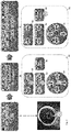
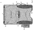
- FIG 1 shows an embodiment of a vehicle seat 10 in a frontal view.
- the vehicle seat 10 essentially comprises a back rest 12 and a seating area 16 onto which a passenger is seated.
- the back rest 12 supports a seated passenger to the back such that he or she can lean against it.
- the vehicle seat 10 is mounted to a floor of the vehicle (not shown) in the installed state by any known mounting techniques like for example by screwing.
- the back rest 12 and the seating area 16 are made of two separate elements that are connected by common connection means to form the complete vehicle seat 10.
- the back rest 12 can be inclined with respect to the seating area 16 at their connection point. Such an inclination of the back rest 12 allows an adjustment of the seat 10 to the passenger and allows a comfortable seating position.
- Manual adjustment devices can be arranged directly at the vehicle seat 10 for setting the inclination of the back rest 12. Further, the back rest 12 inclination can be set by electrical actuators (not shown).
- the vehicle seat 10 comprises a metallic base structure of the seat 10, a variable cushioning above the base structure comprising inflatable cushioning elements, like bladders 21, 22, 62, 72, as well as common cushioning elements, like cold cured foam elements, and a coating based on a fabric material and/or synthetic leather and/or leather on top.
- the back rest 12 comprises two lateral sides 14a, 14b at which protrusions of the cushioning of the back rest 12 are formed in the direction of the passenger for a side support of the passengers.
- the embodiment of a dynamic pneumatic support system 1 of Fig. 1 essentially comprises a side support 20, a lumbar support 60 and a dorsal support 70.
- Each of the supports 20, 60, 70 comprises a certain number of bladders 21, 22, 62, 72.
- the side support 20 comprises a right side support bladders 21, a left side support bladder 22, each being arranged in the respective protrusion on the lateral sides 14a, 14b of the back rest 12.
- the dorsal support 70 comprises one dorsal support bladder 72.
- the lumbar support 60 comprises three separate lumbar support bladders 62a, 62b and 62c which allows adjusting the shape of the back rest 12 in the lumbar area in more defined matter.
- the three lumbar support bladders 62a, 62b and 62c allow to adjust the height of the overall lumbar support 60 in the back rest 12. This provides an improved comfort experience for the passenger.
- Fig. 1 an embodiment with six bladders is shown it is possible to provide the number of bladders 22, 21, 62, 72 as desired.
- the bladders 21, 22, 62, 72 are basically inflatable bags made of a flexible material like soft plastic foil, rubber or the like. In general, the bladders 21, 22, 62, 72 are arranged between the base structure or a suspension mat of the seat 10 and the foam elements, at the so-called foam B-surface level. However, the bladders 21, 22, 62, 72 can also be arranged at the so-called A-surface level, i.e. between the foam elements and a seat trimming. The bladders 21, 22, 62, 72 affect the shape of the vehicle seat 10 when being inflated and/or deflated.
- a pump unit 30 is arranged at the vehicle seat or nearby in order to provide pressurized air to the bladders 21, 22, 62, 72. Thereby, the volume of air fed into each bladder can be controlled by an electronic control unit 40.
- the electronic control unit 40 can be arranged at the vehicle seat 10 and can provide a control panel 80 elsewhere in the car, preferably at the main board of the car. However, in other embodiments the one or more control panels 80 can be arranged for example at each vehicle seat 10.
- the bladders 21, 22, 62, 72 When inflated, the bladders 21, 22, 62, 72 comprise an increased pressure and air volume and are then enlarged. Furthermore, their surface will become harder with increased air pressed into a bladder 21, 22, 62, 72. Thereby, also the pressure within the bladder 21, 22, 62, 72 increases. In such a case, as a result, for example the side support 20 provides a stronger support against stronger occurring gravitational and/or centrifugal, i.e. acceleration, forces A. When air is left from the bladders 21, 22, 62, 72 such that they deflate, their volume and pressure decreases and they become softer. Thus, also the cushioning in the corresponding region of the vehicle seat 10 becomes softer.
- Fig. 2 shows an embodiment of a control panel 80 as well as the corresponding operating sequence for a passenger.
- the electronic control unit 40 is in the first manual adjustment mode and a passenger can manually adjust the cushioning of his seat 10 by activating the corresponding buttons 82, 84, 88 on the control panel 80.
- the 2-way button 88 adjusts the bladders 21 and 22 of the side support.
- the 4-way button 84 adjusts the bladders 62a, 62b and 62c of the lumbar support in their overall height and inflation.
- another 2-way button 82 is provided for manually adjusting the dorsal support bladder 72.
- the passenger When the passenger has finished the manual adjustment, he may activate the "self-adjust" button 86 on the control panel 80 to switch the electronic control unit 40 into the second automatic adjustment mode in which the bladders 21, 22, 62, 72 are automatically self-adjusted.
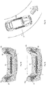
- FIGs. 3a ⁇ 3c an operation scenario of the side support 20 is shown.
- the side support 20 of the dynamic pneumatic support system 1 comprises equally inflated bladders 21, 22 on each lateral side 14a, 14b of the back rest 12. This constitutes the normal state without any particular gravitational and/or acceleration forces.
- a car 100 If a car 100 is moving in a direction D into a curve, as shown in Fig. 3c , it performs a curved motion and centrifugal forces are exerted to the car and its interior. Particularly, a centrifugal acceleration A occurs radially to the outside of the curve and acts on a passenger of the car 100. As a result, the passenger is forced to the right side of the vehicle seat 10 (seen from a sitting perspective of a passenger), in Fig. 3c in the direction of the centrifugal acceleration arrow A.
- the dynamic pneumatic support system 1 controls the bladders 21, 22 of the side support 20 such that bladder 21 on the right lateral side 14a of the back rest 12 is inflated while bladder 22 on the left lateral side 14b of the back rest 12 may be deflated preferably simultaneously, as illustrated in Fig. 3b .
- the more stressed region on the right lateral side 14a of the back rest 12, to which the passenger is pressed is more and harder cushioned than the opposing left lateral side 14b of the back rest 12 in order to keep the passenger in its original comfortable seating position at the center of the vehicle seat 10.
- the deflation of bladder 22 is not always required in this case but may provide a desired softer cushioning on this opposing side. The same applies vice versa when the car 100 performs a curved motion in the opposite direction.
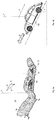
- Fig. 4b shows an uphill motion of the car 100.
- additional gravitational G and acceleration forces A forming a resulting force R are exerted on the car 100 and its passengers.
- the same effect with respect to said gravitational force is achieved when the inclination angle ⁇ is increased with respect to a vertical direction V by an adjustment of the back rest 12 while the car 100 is in normal, i.e. horizontal orientation.
- the absolute inclination angle ⁇ with respect to gravity is of relevance.
- the lumbar and dorsal support 60, 70 of the dynamic pneumatic support system 1 support a passenger seated in vehicle seat 10 as illustrated in Fig. 4a .
- the back rest 12 is inclined, e.g. the back rest is in a relaxing position, and additionally the car is inclined with respect to gravity as illustrated in Fig. 4b .
- the total inclination angle ⁇ is determined by the support system 1 and the bladders 62, 72 are inflated/deflated accordingly. Because of the inclined, backwards, downhill force R a stronger cushioning of the shoulder, i.e. dorsal region, of the passenger is desired while a softer cushioning at the lumbar region may be desired preferably simultaneously.
- the electronic control unit 40 of the dynamic pneumatic support system 1 when the electronic control unit 40 of the dynamic pneumatic support system 1 receives corresponding measurement data of the orientation of the dynamic pneumatic support system 1 and/or acceleration from the sensor unit 50 or from an external sensor, it will control the pump unit 30 to inflate bladder 72 of the dorsal support 70 and to deflate at least one of bladders 62a,b,c of the lumbar support 60 in order to provide the desired comfortable support of the back rest 12 to the passenger.
- the adjustment of the side support 20 may maintain unchanged.
- the initial manually set pressures of the dorsal support bladder 72 and the lumbar support bladders 72 are restored by the control unit 40 and the pump unit 30.
- the pump unit 30 may have separate pressure sensors for each connected bladder 21, 22, 62, 63.
- the backrest 12 may have a backrest angle ⁇ 1 of about 25° with respect to a vertical direction V.
- the pressures of the lumbar support bladder 62, the dorsal support bladder 72 and the side support bladders 21, 22 have been adjusted by the user. Thereby, the lumbar support bladder 62 and the dorsal support bladder 72 may have a user defined pressure of P'.
- the dynamic pneumatic support system 1 in the "self adjust" mode automatically decreases the pressure of the lumbar support bladder 62 to 65% to a predetermined lumbar inclination pressure value of preferably 85% of P'.
- the pressure of the dorsal support bladder 72 is increased up to a predetermined dorsal inclination pressure value of preferably 50% of the maximum allowable pressure Pmax. If the user already had set the pressure of the dorsal support 72 above 50% Pmax, then preferably this pressure is maintained and no further adjustment is made.
- the dynamic pneumatic support system 1 in the "self adjust" mode automatically decreases the pressure of the lumbar support bladder 62 to a predetermined lumbar inclination pressure value of preferably 40% to 65% of P'.
- the pressure of the dorsal support bladder 72 is increased up to a predetermined dorsal inclination pressure value of preferably 75% of the maximum allowable pressure Pmax. If the user already had set the pressure of the dorsal support 72 above 75% Pmax, then preferably this pressure is maintained and no further adjustment is made. In performing a relative adjustment of the pressure of the bladders 62, 72 the original comfortable seating position can be maintained.
- a pressure map is stored in a memory of the electronic control unit 40 containing values of the manual adjustment of the bladders 62, 72 and certain predetermined lumbar and dorsal inclination pressure value, i.e. percentages, for different inclination, orientation and/or acceleration values in order to specifically adapt the seat to all possible driving and manual adjustment conditions.
- the relative adjustment values i.e. percentage values of the initial adjustment values, maybe furthermore adapted or set by the manufacturer to each vehicle seat 10 class according to empirical values, vehicle seat design and/or bladder shape.
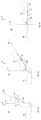
- Fig. 6 shows an embodiment of the dynamic pneumatic support system 1 mounted to a mounting board 2.
- the mounting board 2 can be any plastic and/or metal and/or fiber material plate or can be a suspension mat to be readily integrated into a vehicle seat 10.
- the lumbar support 60 comprises only two separate bladders 62a, 62b each of which is individually connected to a pump unit 30 via separate channels 32. Thereby, air can be filled individually into each of the bladders 62a, 62b or can individually be released from them according to a desired cushioning.
- bladder 72 of the dorsal support 70 is connected to the pump unit 30 via a third separate channel 32.
- the bladders 21, 22 of the side support 20 are mounted and connected to the pump unit 30 via individual channels 32 as well.
- the pump unit 30 may preferably be a pump-valve unit having solenoid valves included, which control the airflow into and out of the respective bladder 21, 22, 62, 72.
- the pump unit 30 comprises an electrically driven air pump, pressure sensors, 3/3 valves for guiding the air into and out of the desired bladder, a printed circuit board, a housing and an air distributor.
- the pump unit 30 is electrically coupled to the electronic control unit 40 and receives power and control signals.
- An overall power supply for the dynamic pneumatic support system 1 may be provided by a battery of the vehicle 100.
- the sensor unit 50 may be mounted to the mounting board 2 as well.
- the electronic control unit 40, the sensor unit 50 and the pump unit 30 are integrated into a common unit.
- the electrically driven air pump is separate from a valve unit, wherein the valve unit, the electronic control unit 40 and the sensor unit 50 are integrated into a common unit.
Landscapes
- Engineering & Computer Science (AREA)
- Aviation & Aerospace Engineering (AREA)
- Transportation (AREA)
- Mechanical Engineering (AREA)
- Seats For Vehicles (AREA)
- Chair Legs, Seat Parts, And Backrests (AREA)
Claims (15)
- Dynamisches pneumatisches Stützsystem (1) zur Integration in eine Rückenlehne (12) eines Fahrzeugsitzes (10), wobei das dynamische pneumatische Stützsystem (1) umfasst:a. mindestens eine Lordosenstützblase (62), die in einem Lordosenbereich einer Rückenlehne (12) angeordnet ist;b. mindestens eine dorsale Stützblase (72), die mindestens an einem Schulterbereich der Rückenlehne (12) angeordnet ist;c. eine Pumpeneinheit (30) zur individuellen Versorgung der Lordosenstützblase (62) und der dorsalen Stützblase (72) mit Luft;d. eine elektronische Steuereinheit (40) zur Steuerung der Pumpeneinheit (30); unde. eine Sensoreinheit (50), die mit der elektronischen Steuereinheit (40) verbunden ist, um automatisch die Orientierung und/oder Beschleunigung (A) der Rückenlehne (12) zu messen und Orientierungsund/oder Beschleunigungsdaten an die elektronische Steuereinheit (40) zu liefern; wobeif. die elektronische Steuereinheit (40), basierend auf den Orientierungsund/oder Beschleunigungsdaten, die Pumpeneinheit (30) steuern kann, um den Druck zumindest der Lordosenstützblase (62) und der dorsalen Stützblase (72) automatisch und individuell zu steuern.
- Dynamisches pneumatisches Stützsystem nach Anspruch 1, wobei die elektronische Steuereinheit (40) den Druck der mindestens einen Lordosenstützblase (62) und der mindestens einen dorsalen Stützblase (72) dynamisch so steuert, dass wenn die Neigung der Rückenlehne (12) gegenüber einer vertikalen Richtung (V) ansteigt:a. der Druck der Lordosenstützblase (62) auf einen vorbestimmten Lordosenneigungsdruckwert abfällt oder auf einem manuell eingestellten Druck unterhalb dieses vorbestimmten Lordosenneigungsdruckwertes gehalten wird; und/oderb. der Druck der dorsalen Stützblase (72) auf einen vorgegebenen dorsalen Neigungsdruckwert ansteigt oder auf einem manuell eingestellten Druck oberhalb dieses vorgegebenen dorsalen Neigungsdruckwertes gehalten wird.
- Dynamisches pneumatisches Stützsystem nach einem der Ansprüche 1 oder 2, wobei die elektronische Steuereinheit (40) den Druck der mindestens einen Lordosenstützblase (62) und der mindestens einen dorsalen Stützblase (72) dynamisch so steuert, dass wenn die Neigung der Rückenlehne (12) gegenüber einer vertikalen Richtung (V) abnimmt:a. der Druck der Lordosenstützblase (62) auf einen gespeicherten, manuell eingestellten Druck oberhalb eines vorbestimmten Lordosenneigungsdruckwertes ansteigt oder auf einem manuell eingestellten Druck unterhalb dieses vorbestimmten Lordosenneigungsdruckwertes gehalten wird; und/oderb. der Druck der dorsalen Stützblase (72) auf einen gespeicherten, manuell eingestellten Druck oberhalb eines vorgegebenen dorsalen Neigungsdruckwertes abfällt oder auf einem manuell eingestellten Druck oberhalb dieses vorgegebenen dorsalen Neigungsdruckwertes gehalten wird.
- Dynamisches pneumatisches Stützsystem nach einem der Ansprüche 1 bis 3, wobei die elektronische Steuereinheit (40) so programmiert ist, dass wenn der Neigungswinkel (a) der Rückenlehne (12) ansteigt,a. der vorgegebene Lordosenneigungsdruckwert abnimmt; und/oderb. der vorgegebene Wert für den dorsalen Neigungsdruck ansteigt.
- Dynamisches pneumatisches Stützsystem nach Anspruch 4, wobei der vorbestimmte Lordosenneigungsdruckwert etwa 40% bis 85% des manuell eingestellten Druckwertes beträgt, vorzugsweise beträgt der vorbestimmte Lordosenneigungsdruckwert etwa 65% bis 85% des manuell eingestellten Druckwertes bei einem Neigungswinkel (a) der Rückenlehne (12) von etwa 45°, und weiter vorzugsweise beträgt der vorbestimmte Lordosenneigungsdruckwert etwa 40% bis 60% des manuell eingestellten Druckwertes bei einem Neigungswinkel (a) der Rückenlehne (12) von etwa 70°.
- Dynamisches pneumatisches Stützsystem nach einem der Ansprüche 4 oder 5, wobei der vorbestimmte dorsale Neigungsdruckwert etwa 50 % bis 75 % des maximalen dorsalen Druckwertes beträgt, vorzugsweise beträgt der vorbestimmte dorsale Neigungsdruckwert etwa 50 % des maximalen dorsalen Druckwertes bei einem Neigungswinkel (a) der Rückenlehne (12) von etwa 45°, und weiter vorzugsweise beträgt der vorbestimmte dorsale Neigungsdruckwert etwa 75 % des maximalen dorsalen Druckwertes bei einem Neigungswinkel (a) der Rückenlehne (12) von etwa 70°.
- Dynamisches pneumatisches Stützsystem nach einem der Ansprüche 1 bis 6, wobei das dynamisch-pneumatische Stützsystem (1) zwei oder drei Lordosenstützblasen (62a, 62b, 62c) umfasst, deren Drücke von der elektronischen Steuereinheit (40) individuell gesteuert werden.
- Dynamisches pneumatisches Stützsystem nach einem der Ansprüche 1 bis 7, wobei das dynamische pneumatische Stützsystem (1) weiterhin umfasst:a. mindestens eine rechte Seitenstützblase (21), die an der rechten Seite der Rückenlehne (12) angeordnet ist; undb. mindestens eine linke Seitenstützblase (22), die an der linken Seite der Rückenlehne (12) angeordnet ist; wobeic. die linke und rechte Seitenstützblase (21, 22) individuell in Fluidverbindung mit der Pumpeneinheit (30) stehen, um die rechte Seitenstützblase (21) und die linke Seitenstützblase (22) individuell mit Luft zu versorgen; undd. die elektronische Steuereinheit (40) kann, basierend auf den Orientierungs- und/oder Beschleunigungsdaten, die Pumpeneinheit (30) steuern, um den Druck zumindest der rechten Seitenstützblase (21) und der linken Seitenstützblase (22) automatisch und individuell zu steuern.
- Dynamisches pneumatisches Stützsystem (1) zur Integration in eine Rückenlehne (12) eines Fahrzeugsitzes (10), wobei das dynamische pneumatische Stützsystem (1) umfasst:a. mindestens eine rechte Seitenstützblase (21), die an der rechten Seite einer Rückenlehne (12) angeordnet ist und mindestens eine linke Seitenstützblase (22), die an der linken Seite der Rückenlehne (12) angeordnet ist;b. die linke und rechte Seitenstützblasen (21, 22) individuell in Fluidverbindung mit einer Pumpeneinheit (30) stehen, um die rechte Seitenstützblase (21) und die linke Seitenstützblase (22) individuell mit Luft zu versorgen;c. eine elektronische Steuereinheit (40), zur Steuerung der Pumpeneinheit (30); undd. eine Sensoreinheit (50), die mit der elektronischen Steuereinheit (40) verbunden ist, um automatisch die Orientierung des dynamischen pneumatischen Stützsystems (1) und/oder die Beschleunigung (A) zu messen und Orientierungs- und/oder Beschleunigungsdaten an die elektronische Steuereinheit (40) zu liefern; wobeie. die elektronische Steuereinheit (40), basierend auf den Orientierungsund/oder Beschleunigungsdaten, die Pumpeneinheit (30) steuern kann, um den Druck zumindest der rechten Seitenstützblase (21) und der linken Seitenstützblase (22) automatisch und individuell zu steuern.
- Dynamisches pneumatisches Stützsystem nach einem der Ansprüche 1 bis 9, wobei die elektronische Steuereinheit (40) zwei Einstellmodi aufweist, wobei in einem ersten manuellen Einstellmodus der Druck der Blasen (21, 22, 62, 72) durch den Benutzer manuell eingestellt werden kann, und wobei in einem zweiten automatischen Einstellmodus der Druck der Blasen (21, 22, 62, 72) automatisch durch die elektronische Steuereinheit (40) eingestellt wird.
- Dynamisches pneumatisches Stützsystem nach einem der Ansprüche 1 bis 10, wobei die elektronische Steuereinheit (40) auf der Grundlage der gemessenen Orientierungsdaten und/oder Beschleunigungsdaten die Pumpeneinheit (30) zur automatischen Steuerung des Drucks der Blasen (21, 22, 62, 72) steuert, um der Beschleunigung (A) und/oder der Schwerkraft (G) entgegenzuwirken.
- Verfahren zur Selbsteinstellung eines dynamischen pneumatischen Stützsystems (1) zur Integration in eine Rückenlehne (12) eines Fahrzeugsitzes (10), wobei das Verfahren die folgenden Schritte aufweist:a. Vorsehen von mindestens einer im Lordosenbereich der Rückenlehne (12) angeordneten Lordosenstützblase (62), mindestens einer mindestens im Schulterbereich der Rückenlehne (12) angeordneten dorsalen Stützblase (72) und einer Pumpeneinheit (30) zur individuellen Versorgung der Lordosenstützblase (62) und der dorsalen Stützblase (72) mit Luft;b. Messen von Orientierungsdaten der Rückenlehne (12) und/oder Beschleunigungsdaten mittels einer Sensoreinheit (50) und Bereitstellen der Orientierungs- und/oder Beschleunigungsdaten an eine elektronische Steuereinheit (40);c. Automatisches Steuern der Pumpeneinheit (30) durch die elektronische Steuereinheit (40) basierend auf den Orientierungsdaten und/oder den Beschleunigungsdaten; undd. Automatisches Steuern des Drucks der mindestens einen Lordosenstützblase (62) und der mindestens einen dorsalen Stützblase (72) durch die Pumpeneinheit (30) entsprechend den gemessenen Orientierungs- und/oder Beschleunigungsdaten.
- Verfahren zur Selbsteinstellung eines dynamischen pneumatischen Stützsystems (1) nach Anspruch 12, weiterhin aufweisend die folgenden Schritte:a. Vorsehen mindestens einer rechten Seitenstützblase (21), die an der rechten Seite der Rückenlehne (12) angeordnet ist, und mindestens einer linken Seitenstützblase (22), die an der linken Seite der Rückenlehne (12) angeordnet ist, wobei die linke und die rechte Seitenstützblasen (21, 22) individuell in Fluidverbindung mit der Pumpeneinheit (30) stehen, um die rechte Seitenstützblase (21) und die linke Seitenstützblase (22) individuell mit Luft zu versorgen; undb. Automatisches Steuern des Drucks der mindestens einen rechten Seitenstützblase (21) und der mindestens einen linken Seitenstützblase (22) durch die Pumpeneinheit (30) entsprechend den gemessenen Orientierungs- und/oder Beschleunigungsdaten.
- Verfahren zur Selbsteinstellung eines dynamischen pneumatischen Stützsystems (1) nach einem der Ansprüche 12 oder 13, wobei der Schritt der automatischen Steuerung die Schritte der Erhöhung des Drucks in einer der Blasen (21, 22, 62, 72) und der gleichzeitigen Verringerung des Drucks der entsprechenden anderen Blase (21, 22, 62, 72) umfasst.
- Fahrzeugsitz (10) aufweisend:a. eine Rückenlehne (12); undb. ein in die Rückenlehne (12) integriertes dynamisches pneumatisches Stützsystem (1) nach einem der Ansprüche 1 bis 11.
Priority Applications (1)
| Application Number | Priority Date | Filing Date | Title |
|---|---|---|---|
| EP18174781.7A EP3575144B1 (de) | 2018-05-29 | 2018-05-29 | Dynamisches pneumatisches stützsystem |
Applications Claiming Priority (1)
| Application Number | Priority Date | Filing Date | Title |
|---|---|---|---|
| EP18174781.7A EP3575144B1 (de) | 2018-05-29 | 2018-05-29 | Dynamisches pneumatisches stützsystem |
Publications (2)
| Publication Number | Publication Date |
|---|---|
| EP3575144A1 EP3575144A1 (de) | 2019-12-04 |
| EP3575144B1 true EP3575144B1 (de) | 2021-10-20 |
Family
ID=62486436
Family Applications (1)
| Application Number | Title | Priority Date | Filing Date |
|---|---|---|---|
| EP18174781.7A Active EP3575144B1 (de) | 2018-05-29 | 2018-05-29 | Dynamisches pneumatisches stützsystem |
Country Status (1)
| Country | Link |
|---|---|
| EP (1) | EP3575144B1 (de) |
Families Citing this family (18)
| Publication number | Priority date | Publication date | Assignee | Title |
|---|---|---|---|---|
| US11858392B2 (en) * | 2019-03-01 | 2024-01-02 | Ts Tech Co., Ltd. | Vehicle seat and vehicle provided with vehicle seat |
| GB2594798B (en) * | 2020-04-07 | 2024-04-17 | Ami Ind Inc | Lumbar support systems for ejection seat |
| US11613366B2 (en) | 2020-04-07 | 2023-03-28 | Ami Industries, Inc. | Lumbar support systems for ejection seat |
| CN113942468A (zh) * | 2020-07-15 | 2022-01-18 | 采埃孚汽车科技(上海)有限公司 | 车辆的气动座椅控制系统、控制方法及计算机可读介质 |
| CN112009314B (zh) * | 2020-08-10 | 2022-02-22 | 广州汽车集团股份有限公司 | 一种车辆座椅侧翼调节方法、装置及系统 |
| CN112089246A (zh) * | 2020-11-03 | 2020-12-18 | 苏州贝氪智能科技有限公司 | 背部跟随支撑装置及办公椅 |
| CN116710320A (zh) * | 2021-01-21 | 2023-09-05 | 提爱思科技股份有限公司 | 交通工具用座椅 |
| WO2022158546A1 (ja) * | 2021-01-21 | 2022-07-28 | テイ・エス テック株式会社 | 乗物用シート |
| CN115139882A (zh) * | 2021-03-29 | 2022-10-04 | 本田技研工业株式会社 | 座椅调节装置 |
| CN113799665B (zh) * | 2021-10-29 | 2022-11-22 | 北京经纬恒润科技股份有限公司 | 一种座椅支撑控制方法及装置 |
| CN115486651A (zh) * | 2022-09-05 | 2022-12-20 | 贾丽红 | 带有传感器的气动腰托 |
| CN115848249A (zh) * | 2022-11-21 | 2023-03-28 | 舒茨曼座椅(宁波)有限公司 | 腰托及其控制方法和装置、座椅、及车辆 |
| CN115837870A (zh) * | 2022-12-07 | 2023-03-24 | 合众新能源汽车股份有限公司 | 汽车座椅靠背的自动调节装置和方法 |
| CN116394960B (zh) * | 2022-12-19 | 2026-03-27 | 江西科技学院 | 基于多种融合疲劳特征的疲劳驾驶预警方法及系统 |
| CN116279040B (zh) * | 2023-03-10 | 2026-02-03 | 安闻汽车技术(天津)有限公司 | 侧翼可随动的气动控制系统、汽车座椅及气动控制方法 |
| CN116424170A (zh) * | 2023-04-28 | 2023-07-14 | 重庆长安汽车股份有限公司 | 一种零重力座椅总成的腰部支撑模块控制方法、系统、汽车、设备及介质 |
| CN116985683A (zh) * | 2023-08-09 | 2023-11-03 | 广汽本田汽车有限公司 | 基于车辆状态的座椅动态调节方法、系统、装置及介质 |
| CN117246199A (zh) * | 2023-09-20 | 2023-12-19 | 中国第一汽车股份有限公司 | 车辆座椅控制方法、装置、电子设备、及存储介质 |
Family Cites Families (8)
| Publication number | Priority date | Publication date | Assignee | Title |
|---|---|---|---|---|
| US5707109A (en) * | 1996-02-02 | 1998-01-13 | Lear Corporation | Acceleration compensating vehicular seat assembly |
| AU5314799A (en) * | 1998-07-15 | 2000-02-07 | Rostra Precision Controls, Inc. | Electronic control system for a variable support mechanism |
| DE19938698A1 (de) * | 1999-08-14 | 2001-02-15 | Volkswagen Ag | Fahrzeugsitz |
| DE102006004071A1 (de) | 2006-01-28 | 2007-08-02 | Recaro Aircraft Seating Gmbh & Co. Kg | Sitzpneumatikvorrichtung |
| DE102007053119A1 (de) | 2007-11-08 | 2009-05-14 | Bayerische Motoren Werke Aktiengesellschaft | Verfahren und Vorrichtung zum Einstellen eines Sitzes sowie Sitz |
| DE102010020642A1 (de) | 2010-05-15 | 2011-11-17 | Dornier Technologie Gmbh & Co. Kg | Pneumatiksteuerung für Fahrzeugsitz, insbesondere Fluggastsitz |
| JP5962485B2 (ja) | 2012-12-17 | 2016-08-03 | トヨタ紡織株式会社 | 車両用シート |
| US10632866B2 (en) * | 2016-06-03 | 2020-04-28 | Faurecia Automotive Seating, Llc | Movement system for a vehicle seat |
-
2018
- 2018-05-29 EP EP18174781.7A patent/EP3575144B1/de active Active
Non-Patent Citations (1)
| Title |
|---|
| None * |
Also Published As
| Publication number | Publication date |
|---|---|
| EP3575144A1 (de) | 2019-12-04 |
Similar Documents
| Publication | Publication Date | Title |
|---|---|---|
| EP3575144B1 (de) | Dynamisches pneumatisches stützsystem | |
| US10427554B2 (en) | Occupant support | |
| CN105799566B (zh) | 柔性车辆座椅 | |
| US5558398A (en) | Self-adjusting seating system | |
| US10384565B2 (en) | Adjustable seat assembly | |
| CN112477716A (zh) | 一种具有自适应调节功能的汽车座椅及其控制方法 | |
| US10455945B2 (en) | Thoracic region comfort seating system | |
| US10328829B2 (en) | Thoracic region comfort vehicle seating system with pneumatic adjustment | |
| EP3529154B1 (de) | Fahrgastsitz mit seitlicher schlafstützanordnung | |
| CN106853784B (zh) | 骨盆和骶骨囊组件及其调节方法 | |
| US20110272993A1 (en) | Cushion for a Seat and Method of Adapting Same | |
| CN106494279A (zh) | 用于车辆座椅总成的气囊系统 | |
| CN100430263C (zh) | 汽车座椅 | |
| EP3526076B1 (de) | Verstellbarer sitz | |
| CN215793340U (zh) | 一种座椅气袋气动控制系统 | |
| US11618348B2 (en) | Systems and methods of adjusting the hardness of a passenger seat | |
| CN104044495B (zh) | 具有气动调节部的胸部区域舒适的交通工具座椅系统 | |
| CN112477718A (zh) | 一种具有自适应调节功能的座椅头枕及其控制方法 | |
| WO2024026130A1 (en) | Multi-way lumbar support system | |
| CN110949188A (zh) | 一种汽车座椅硬度的调节系统及调节方法 | |
| CN210554343U (zh) | 一种软硬度可调的汽车座椅 | |
| CN215204561U (zh) | 一种具有自适应调节功能的汽车座椅 | |
| US20250376097A1 (en) | Seat and method of adjusting a size and comfort of the seat | |
| CZ202174A3 (cs) | Sedadlo do automobilu a automobil s tímto sedadlem | |
| JPH11342775A (ja) | 着座姿勢保持可能な車両用座席 |
Legal Events
| Date | Code | Title | Description |
|---|---|---|---|
| PUAI | Public reference made under article 153(3) epc to a published international application that has entered the european phase |
Free format text: ORIGINAL CODE: 0009012 |
|
| STAA | Information on the status of an ep patent application or granted ep patent |
Free format text: STATUS: THE APPLICATION HAS BEEN PUBLISHED |
|
| AK | Designated contracting states |
Kind code of ref document: A1 Designated state(s): AL AT BE BG CH CY CZ DE DK EE ES FI FR GB GR HR HU IE IS IT LI LT LU LV MC MK MT NL NO PL PT RO RS SE SI SK SM TR |
|
| AX | Request for extension of the european patent |
Extension state: BA ME |
|
| STAA | Information on the status of an ep patent application or granted ep patent |
Free format text: STATUS: REQUEST FOR EXAMINATION WAS MADE |
|
| 17P | Request for examination filed |
Effective date: 20200414 |
|
| RBV | Designated contracting states (corrected) |
Designated state(s): AL AT BE BG CH CY CZ DE DK EE ES FI FR GB GR HR HU IE IS IT LI LT LU LV MC MK MT NL NO PL PT RO RS SE SI SK SM TR |
|
| GRAJ | Information related to disapproval of communication of intention to grant by the applicant or resumption of examination proceedings by the epo deleted |
Free format text: ORIGINAL CODE: EPIDOSDIGR1 |
|
| STAA | Information on the status of an ep patent application or granted ep patent |
Free format text: STATUS: GRANT OF PATENT IS INTENDED |
|
| GRAP | Despatch of communication of intention to grant a patent |
Free format text: ORIGINAL CODE: EPIDOSNIGR1 |
|
| INTG | Intention to grant announced |
Effective date: 20201007 |
|
| GRAJ | Information related to disapproval of communication of intention to grant by the applicant or resumption of examination proceedings by the epo deleted |
Free format text: ORIGINAL CODE: EPIDOSDIGR1 |
|
| STAA | Information on the status of an ep patent application or granted ep patent |
Free format text: STATUS: REQUEST FOR EXAMINATION WAS MADE |
|
| INTC | Intention to grant announced (deleted) | ||
| GRAP | Despatch of communication of intention to grant a patent |
Free format text: ORIGINAL CODE: EPIDOSNIGR1 |
|
| STAA | Information on the status of an ep patent application or granted ep patent |
Free format text: STATUS: GRANT OF PATENT IS INTENDED |
|
| GRAJ | Information related to disapproval of communication of intention to grant by the applicant or resumption of examination proceedings by the epo deleted |
Free format text: ORIGINAL CODE: EPIDOSDIGR1 |
|
| STAA | Information on the status of an ep patent application or granted ep patent |
Free format text: STATUS: REQUEST FOR EXAMINATION WAS MADE |
|
| GRAP | Despatch of communication of intention to grant a patent |
Free format text: ORIGINAL CODE: EPIDOSNIGR1 |
|
| GRAJ | Information related to disapproval of communication of intention to grant by the applicant or resumption of examination proceedings by the epo deleted |
Free format text: ORIGINAL CODE: EPIDOSDIGR1 |
|
| INTG | Intention to grant announced |
Effective date: 20210331 |
|
| GRAP | Despatch of communication of intention to grant a patent |
Free format text: ORIGINAL CODE: EPIDOSNIGR1 |
|
| STAA | Information on the status of an ep patent application or granted ep patent |
Free format text: STATUS: GRANT OF PATENT IS INTENDED |
|
| INTC | Intention to grant announced (deleted) | ||
| INTG | Intention to grant announced |
Effective date: 20210504 |
|
| GRAS | Grant fee paid |
Free format text: ORIGINAL CODE: EPIDOSNIGR3 |
|
| GRAA | (expected) grant |
Free format text: ORIGINAL CODE: 0009210 |
|
| STAA | Information on the status of an ep patent application or granted ep patent |
Free format text: STATUS: THE PATENT HAS BEEN GRANTED |
|
| AK | Designated contracting states |
Kind code of ref document: B1 Designated state(s): AL AT BE BG CH CY CZ DE DK EE ES FI FR GB GR HR HU IE IS IT LI LT LU LV MC MK MT NL NO PL PT RO RS SE SI SK SM TR |
|
| REG | Reference to a national code |
Ref country code: GB Ref legal event code: FG4D |
|
| REG | Reference to a national code |
Ref country code: CH Ref legal event code: EP |
|
| REG | Reference to a national code |
Ref country code: DE Ref legal event code: R096 Ref document number: 602018025202 Country of ref document: DE |
|
| REG | Reference to a national code |
Ref country code: IE Ref legal event code: FG4D |
|
| REG | Reference to a national code |
Ref country code: AT Ref legal event code: REF Ref document number: 1439676 Country of ref document: AT Kind code of ref document: T Effective date: 20211115 |
|
| REG | Reference to a national code |
Ref country code: LT Ref legal event code: MG9D |
|
| REG | Reference to a national code |
Ref country code: NL Ref legal event code: MP Effective date: 20211020 |
|
| REG | Reference to a national code |
Ref country code: AT Ref legal event code: MK05 Ref document number: 1439676 Country of ref document: AT Kind code of ref document: T Effective date: 20211020 |
|
| PG25 | Lapsed in a contracting state [announced via postgrant information from national office to epo] |
Ref country code: RS Free format text: LAPSE BECAUSE OF FAILURE TO SUBMIT A TRANSLATION OF THE DESCRIPTION OR TO PAY THE FEE WITHIN THE PRESCRIBED TIME-LIMIT Effective date: 20211020 Ref country code: LT Free format text: LAPSE BECAUSE OF FAILURE TO SUBMIT A TRANSLATION OF THE DESCRIPTION OR TO PAY THE FEE WITHIN THE PRESCRIBED TIME-LIMIT Effective date: 20211020 Ref country code: FI Free format text: LAPSE BECAUSE OF FAILURE TO SUBMIT A TRANSLATION OF THE DESCRIPTION OR TO PAY THE FEE WITHIN THE PRESCRIBED TIME-LIMIT Effective date: 20211020 Ref country code: BG Free format text: LAPSE BECAUSE OF FAILURE TO SUBMIT A TRANSLATION OF THE DESCRIPTION OR TO PAY THE FEE WITHIN THE PRESCRIBED TIME-LIMIT Effective date: 20220120 Ref country code: AT Free format text: LAPSE BECAUSE OF FAILURE TO SUBMIT A TRANSLATION OF THE DESCRIPTION OR TO PAY THE FEE WITHIN THE PRESCRIBED TIME-LIMIT Effective date: 20211020 |
|
| PG25 | Lapsed in a contracting state [announced via postgrant information from national office to epo] |
Ref country code: IS Free format text: LAPSE BECAUSE OF FAILURE TO SUBMIT A TRANSLATION OF THE DESCRIPTION OR TO PAY THE FEE WITHIN THE PRESCRIBED TIME-LIMIT Effective date: 20220220 Ref country code: SE Free format text: LAPSE BECAUSE OF FAILURE TO SUBMIT A TRANSLATION OF THE DESCRIPTION OR TO PAY THE FEE WITHIN THE PRESCRIBED TIME-LIMIT Effective date: 20211020 Ref country code: PT Free format text: LAPSE BECAUSE OF FAILURE TO SUBMIT A TRANSLATION OF THE DESCRIPTION OR TO PAY THE FEE WITHIN THE PRESCRIBED TIME-LIMIT Effective date: 20220221 Ref country code: PL Free format text: LAPSE BECAUSE OF FAILURE TO SUBMIT A TRANSLATION OF THE DESCRIPTION OR TO PAY THE FEE WITHIN THE PRESCRIBED TIME-LIMIT Effective date: 20211020 Ref country code: NO Free format text: LAPSE BECAUSE OF FAILURE TO SUBMIT A TRANSLATION OF THE DESCRIPTION OR TO PAY THE FEE WITHIN THE PRESCRIBED TIME-LIMIT Effective date: 20220120 Ref country code: NL Free format text: LAPSE BECAUSE OF FAILURE TO SUBMIT A TRANSLATION OF THE DESCRIPTION OR TO PAY THE FEE WITHIN THE PRESCRIBED TIME-LIMIT Effective date: 20211020 Ref country code: LV Free format text: LAPSE BECAUSE OF FAILURE TO SUBMIT A TRANSLATION OF THE DESCRIPTION OR TO PAY THE FEE WITHIN THE PRESCRIBED TIME-LIMIT Effective date: 20211020 Ref country code: HR Free format text: LAPSE BECAUSE OF FAILURE TO SUBMIT A TRANSLATION OF THE DESCRIPTION OR TO PAY THE FEE WITHIN THE PRESCRIBED TIME-LIMIT Effective date: 20211020 Ref country code: ES Free format text: LAPSE BECAUSE OF FAILURE TO SUBMIT A TRANSLATION OF THE DESCRIPTION OR TO PAY THE FEE WITHIN THE PRESCRIBED TIME-LIMIT Effective date: 20211020 |
|
| REG | Reference to a national code |
Ref country code: DE Ref legal event code: R097 Ref document number: 602018025202 Country of ref document: DE |
|
| PG25 | Lapsed in a contracting state [announced via postgrant information from national office to epo] |
Ref country code: SM Free format text: LAPSE BECAUSE OF FAILURE TO SUBMIT A TRANSLATION OF THE DESCRIPTION OR TO PAY THE FEE WITHIN THE PRESCRIBED TIME-LIMIT Effective date: 20211020 Ref country code: SK Free format text: LAPSE BECAUSE OF FAILURE TO SUBMIT A TRANSLATION OF THE DESCRIPTION OR TO PAY THE FEE WITHIN THE PRESCRIBED TIME-LIMIT Effective date: 20211020 Ref country code: RO Free format text: LAPSE BECAUSE OF FAILURE TO SUBMIT A TRANSLATION OF THE DESCRIPTION OR TO PAY THE FEE WITHIN THE PRESCRIBED TIME-LIMIT Effective date: 20211020 Ref country code: EE Free format text: LAPSE BECAUSE OF FAILURE TO SUBMIT A TRANSLATION OF THE DESCRIPTION OR TO PAY THE FEE WITHIN THE PRESCRIBED TIME-LIMIT Effective date: 20211020 Ref country code: DK Free format text: LAPSE BECAUSE OF FAILURE TO SUBMIT A TRANSLATION OF THE DESCRIPTION OR TO PAY THE FEE WITHIN THE PRESCRIBED TIME-LIMIT Effective date: 20211020 Ref country code: CZ Free format text: LAPSE BECAUSE OF FAILURE TO SUBMIT A TRANSLATION OF THE DESCRIPTION OR TO PAY THE FEE WITHIN THE PRESCRIBED TIME-LIMIT Effective date: 20211020 |
|
| PLBE | No opposition filed within time limit |
Free format text: ORIGINAL CODE: 0009261 |
|
| STAA | Information on the status of an ep patent application or granted ep patent |
Free format text: STATUS: NO OPPOSITION FILED WITHIN TIME LIMIT |
|
| 26N | No opposition filed |
Effective date: 20220721 |
|
| PG25 | Lapsed in a contracting state [announced via postgrant information from national office to epo] |
Ref country code: AL Free format text: LAPSE BECAUSE OF FAILURE TO SUBMIT A TRANSLATION OF THE DESCRIPTION OR TO PAY THE FEE WITHIN THE PRESCRIBED TIME-LIMIT Effective date: 20211020 |
|
| PG25 | Lapsed in a contracting state [announced via postgrant information from national office to epo] |
Ref country code: SI Free format text: LAPSE BECAUSE OF FAILURE TO SUBMIT A TRANSLATION OF THE DESCRIPTION OR TO PAY THE FEE WITHIN THE PRESCRIBED TIME-LIMIT Effective date: 20211020 |
|
| REG | Reference to a national code |
Ref country code: CH Ref legal event code: PL |
|
| REG | Reference to a national code |
Ref country code: BE Ref legal event code: MM Effective date: 20220531 |
|
| GBPC | Gb: european patent ceased through non-payment of renewal fee |
Effective date: 20220529 |
|
| PG25 | Lapsed in a contracting state [announced via postgrant information from national office to epo] |
Ref country code: MC Free format text: LAPSE BECAUSE OF FAILURE TO SUBMIT A TRANSLATION OF THE DESCRIPTION OR TO PAY THE FEE WITHIN THE PRESCRIBED TIME-LIMIT Effective date: 20211020 Ref country code: LU Free format text: LAPSE BECAUSE OF NON-PAYMENT OF DUE FEES Effective date: 20220529 Ref country code: LI Free format text: LAPSE BECAUSE OF NON-PAYMENT OF DUE FEES Effective date: 20220531 Ref country code: CH Free format text: LAPSE BECAUSE OF NON-PAYMENT OF DUE FEES Effective date: 20220531 |
|
| PG25 | Lapsed in a contracting state [announced via postgrant information from national office to epo] |
Ref country code: IE Free format text: LAPSE BECAUSE OF NON-PAYMENT OF DUE FEES Effective date: 20220529 Ref country code: FR Free format text: LAPSE BECAUSE OF NON-PAYMENT OF DUE FEES Effective date: 20220531 |
|
| PG25 | Lapsed in a contracting state [announced via postgrant information from national office to epo] |
Ref country code: IT Free format text: LAPSE BECAUSE OF FAILURE TO SUBMIT A TRANSLATION OF THE DESCRIPTION OR TO PAY THE FEE WITHIN THE PRESCRIBED TIME-LIMIT Effective date: 20211020 Ref country code: GB Free format text: LAPSE BECAUSE OF NON-PAYMENT OF DUE FEES Effective date: 20220529 Ref country code: BE Free format text: LAPSE BECAUSE OF NON-PAYMENT OF DUE FEES Effective date: 20220531 |
|
| PG25 | Lapsed in a contracting state [announced via postgrant information from national office to epo] |
Ref country code: HU Free format text: LAPSE BECAUSE OF FAILURE TO SUBMIT A TRANSLATION OF THE DESCRIPTION OR TO PAY THE FEE WITHIN THE PRESCRIBED TIME-LIMIT; INVALID AB INITIO Effective date: 20180529 |
|
| PG25 | Lapsed in a contracting state [announced via postgrant information from national office to epo] |
Ref country code: MK Free format text: LAPSE BECAUSE OF FAILURE TO SUBMIT A TRANSLATION OF THE DESCRIPTION OR TO PAY THE FEE WITHIN THE PRESCRIBED TIME-LIMIT Effective date: 20211020 Ref country code: CY Free format text: LAPSE BECAUSE OF FAILURE TO SUBMIT A TRANSLATION OF THE DESCRIPTION OR TO PAY THE FEE WITHIN THE PRESCRIBED TIME-LIMIT Effective date: 20211020 |
|
| PG25 | Lapsed in a contracting state [announced via postgrant information from national office to epo] |
Ref country code: MT Free format text: LAPSE BECAUSE OF FAILURE TO SUBMIT A TRANSLATION OF THE DESCRIPTION OR TO PAY THE FEE WITHIN THE PRESCRIBED TIME-LIMIT Effective date: 20211020 |
|
| PG25 | Lapsed in a contracting state [announced via postgrant information from national office to epo] |
Ref country code: GR Free format text: LAPSE BECAUSE OF NON-PAYMENT OF DUE FEES Effective date: 20211020 |
|
| PG25 | Lapsed in a contracting state [announced via postgrant information from national office to epo] |
Ref country code: GR Free format text: LAPSE BECAUSE OF NON-PAYMENT OF DUE FEES Effective date: 20211020 |
|
| PGFP | Annual fee paid to national office [announced via postgrant information from national office to epo] |
Ref country code: DE Payment date: 20250526 Year of fee payment: 8 |
|
| PG25 | Lapsed in a contracting state [announced via postgrant information from national office to epo] |
Ref country code: TR Free format text: LAPSE BECAUSE OF FAILURE TO SUBMIT A TRANSLATION OF THE DESCRIPTION OR TO PAY THE FEE WITHIN THE PRESCRIBED TIME-LIMIT Effective date: 20211020 |