EP3575145B1 - Structure de cadre de dossier de siège de véhicule - Google Patents
Structure de cadre de dossier de siège de véhicule Download PDFInfo
- Publication number
- EP3575145B1 EP3575145B1 EP18745414.5A EP18745414A EP3575145B1 EP 3575145 B1 EP3575145 B1 EP 3575145B1 EP 18745414 A EP18745414 A EP 18745414A EP 3575145 B1 EP3575145 B1 EP 3575145B1
- Authority
- EP
- European Patent Office
- Prior art keywords
- width direction
- seat width
- frame
- vehicle
- wall part
- Prior art date
- Legal status (The legal status is an assumption and is not a legal conclusion. Google has not performed a legal analysis and makes no representation as to the accuracy of the status listed.)
- Active
Links
Images

Classifications
-
- B—PERFORMING OPERATIONS; TRANSPORTING
- B60—VEHICLES IN GENERAL
- B60N—SEATS SPECIALLY ADAPTED FOR VEHICLES; VEHICLE PASSENGER ACCOMMODATION NOT OTHERWISE PROVIDED FOR
- B60N2/00—Seats specially adapted for vehicles; Arrangement or mounting of seats in vehicles
- B60N2/64—Back-rests or cushions
-
- B—PERFORMING OPERATIONS; TRANSPORTING
- B60—VEHICLES IN GENERAL
- B60N—SEATS SPECIALLY ADAPTED FOR VEHICLES; VEHICLE PASSENGER ACCOMMODATION NOT OTHERWISE PROVIDED FOR
- B60N2/00—Seats specially adapted for vehicles; Arrangement or mounting of seats in vehicles
- B60N2/68—Seat frames
Definitions
- the present invention relates to a vehicular seatback frame structure according to the preamble of claim 1.
- a vehicular seat is provided with a seat cushion on which a passenger is seated, and a seatback that supports upper limbs of a passenger.
- a frame configuring the seatback which is formed of a resin material such as a fiber-reinforced composite material, as disclosed in JP 2014-65341 , for example.
- the seatback frame in this example has a hollow closed cross-sectional structure for an improvement on strength and rigidity, further reducing weight of the seat.
- US 2004 0227389 A1 discloses a seat back frame for a vehicle seat that includes first and second side members made of ultra-high tensile strength steel, an upper member and a lower member arranged between the two side members and also made of ultra-high tensile strength steel.
- a vehicle seat back frame structure is known that has planar side frames and a cross member disposed between the upper ends of the side frames.
- the material of the elements described JP 2010 046162 A is not disclosed.
- WO 2013 021484 A1 presents a seat back frame with two side frames and an upper frame formed by a seat frame material obtained by laminating a plurality of sheets of a sheet-like resin material, in which a reinforcing fiber material is inserted. The lateral ends of the upper frame are connected to the upper ends of the side frames.
- the seatback frame since the seatback frame is all formed of the closed cross-sectional structure, the seatback frame has the structure having higher rigidity than a steel seat frame for a compact car or a lightweight car that does not require high rigidity, and is possibly overengineered, which is called overspecification. Following the overspecification, the seat weight is also possibly heavy.
- the center of the upper cross member is deformed to bend to the backward side.
- a load in a deviation direction is input to a joining part formed by the adhesive agent.
- the adhesive agent is possibly lower in strength relative to the deviation load than to the shear load. Therefore, the generation of this deformation is not desirable for the bonding structure using the adhesive agent.
- a section for supporting the headrest is provided in the upper part of the seatback frame, but in many cases, the section is formed in a complicated shape. Therefore, in a case of forming the seatback frame of a fiber-reinforced resin material, degree of difficulty in forming is high, possibly leading to reduced productivity.
- the present invention is made for solving the foregoing problems, and an object of the present invention is to provide a vehicular seatback frame structure that can suppress separation of a bond in a bonded section of a closed cross-sectional structure provided in an upper cross member configuring a seatback frame and ensure the rigidity of the upper cross member.
- a vehicular seatback frame structure comprises the sum of features defined by claim 1.
- the seatback frame structure comprises two resin side frames that extend in a vehicle vertical direction and are arranged to be spaced in a seat width direction, and an upper cross member that extends in the seat width direction and connects upper parts of the respective side frames.
- the upper cross member includes a first member extending in the seat width direction, and a second member disposed under the first member and extending in the seat width direction.
- the first member has a lower part that is provided with a downward opening part extending in the seat width direction and opening to the vehicle downward side
- the second member has an upper part that is provided with an upward opening part extending in the seat width direction and opening to the vehicle upward side
- the upper cross member has a closed cross-sectional structure configured by the downward opening part of the first member and the upward opening part of the second member.
- a vehicle vertical position of a joining part between the upper cross member and the side frame is disposed closer to the vehicle downward side than the vehicle vertical position of the closed cross-sectional structure of the upper cross member and closer to the vehicle upward side than the vehicle vertical position in which a front-back direction width of the side frame is the smallest.
- the present invention it is possible to suppress the separation of the bond in the bonded section of the closed cross-sectional structure provided in the upper cross member configuring the seatback frame and ensure the rigidity of the upper cross member.
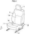
- the vehicular seatback frame structure according to the present embodiment will be explained, as shown in Figure 1 , by taking a seatback frame structure of a vehicular seat for a single passenger such as an operator's seat or a front passenger seat, as an example.
- the vehicular seat is provided with a seat cushion 1, a seatback 2, and a headrest 4.
- the seat cushion 1 has, as shown in Figure 1 and Figure 2 , a seating surface part 1a on which a passenger is seated.
- the seat cushion 1 is configured to be slidable on rails 5 installed on a vehicle body floor panel (not shown). An explanation on a slide mechanism for sliding the seat cushion 1 is omitted.
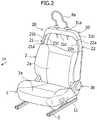
- Seat cushion frames 11 configuring a framework of the seat cushion 1 are provided in the inside of the seat cushion 1. Although detailed illustration is omitted, the seat cushion frames 11 are arranged in both side parts in the left and right of the seating surface part 1a in the inside of the seat cushion 1.
- the left and right herein correspond to the left and right when a passenger seated on the vehicular seat is looking at the vehicle forward side. That is, the seat cushion frame 11 as virtually shown in Figure 2 is the left seat cushion frame 11.
- the seat cushion frame 11 is a plate-shaped member that is formed of a carbon fiber-reinforced resin material, and extends in the vehicle front-back direction in a state of erecting to the vehicle body floor panel as shown in Figure 2 .
- a lower part of the seat cushion frame 11 is configured to be slidable on the rail 5.
- the seatback 2 is, as shown in Figure 1 and Figure 2 , a member having a backrest part 2a that can support upper limbs of a passenger.
- the seatback 2 is configured to be relatively rotatable to the seat cushion 1 by a reclining mechanism 39.
- the headrest 4 is detachably attached to an upper part of the seatback 2.
- a seatback frame 20 configuring a framework of the seatback 2 is, as shown in Figure 2 , provided in the inside of the seatback 2.
- the seatback frame 20 has a right longitudinal frame (a side frame) 21 and a left longitudinal frame (a side frame) 22, which are formed of a carbon fiber-reinforced resin material.
- the right longitudinal frame 21 and the left longitudinal frame 22 are arranged in the left and the right (in both the side parts in the seat width direction) of the backrest part 2a of the seatback 2 and are arranged in parallel to be spaced away from each other in the seat width direction and to be paired.
- the right longitudinal frame 21 is a member extending to the vehicle upward side from a rear part of a right seat cushion frame (not shown), and is rotatably attached to the right seat cushion frame through the reclining mechanism 39.
- the right longitudinal frame 21 includes, as shown in Figure 2 and Figure 3 , a longitudinal wall part 21a having a surface exposed to an outer side and an inner side in the vehicle width direction, and flange parts 21b, 21c extending from an edge end of the longitudinal wall part 21a to the central side in the seat width direction, which are integrally formed.
- the rear flange part 21c extending from a rear end of the longitudinal wall part 21a to the central side in the seat width direction is longer in an extension length (a length in the seat width direction) than the front flange part 21b extending from a front end of the longitudinal wall part 21a to the central side in the seat width direction.
- An inner opening part opening in the seat width direction is configured by the flange parts 21b, 21c.
- a ]-shaped plane cross section (an open cross-sectional structure) opening to the central side (the inner side) in the seat width direction is formed by the longitudinal wall part 21a, the front flange part 21b and the rear flange part 21c.
- a lower part of the longitudinal wall part 21a is provided with an installation part 21d for attaching the reclining mechanism 39.
- the installation part 21d in this example has one large diameter hole 21e and four small diameter holes 21f arranged in a radial outer side of the large diameter hole 21e.
- the small diameter holes 21f are arranged to be equally spaced in the periphery of the large diameter hole 21e.
- the reclining mechanism 39 is attached to the holes 21e, 21f by fastening members or the like.
- a detailed explanation of the reclining mechanism 39 is omitted, but main bodies of the reclining mechanism 39 are arranged to both the outer sides of the left and right longitudinal frames 21, 22 in the seat width direction, and are joined by a pipe to form the reclining mechanism 39.
- the left longitudinal frame 22 is, as shown in Figure 2 , a member extending from a rear part of the left seat cushion frame 11 to the vehicle upward side, and is rotatably attached to the left seat cushion frame 11 through the reclining mechanism 39.
- the left longitudinal frame 22 includes, as shown in Figure 3 and as similar to the right longitudinal frame 21, the longitudinal wall part 22a, the front flange part 22b and the rear flange part 22c, which are integrally formed to configure a ]-shaped plane cross section (an open cross-sectional structure) opening to the central side (the inner side) in the seat width direction.
- a lower part of the longitudinal wall part 22a in the left longitudinal frame 22 is, as similar to the longitudinal wall part 21a of the right longitudinal frame 21, provided with an installation part 22d for attaching the reclining mechanism 39.
- the installation part 22d has, as similar to the right longitudinal frame 21, one large diameter hole 22e and four small diameter holes 22f arranged in a radial outer side of the large diameter hole 22e.
- the seatback frame 20 has, as shown in Figure 3 , an upper cross member 30 connecting an upper part of the right longitudinal frame 21 and an upper part of the left longitudinal frame 22.
- an explanation will be made of the configuration of the upper cross member 30.
- the upper cross member 30 is a member extending in the seat width direction, and has two members, that is, a first member 31 and a second member 32.
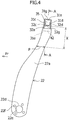
- the first member 31 includes, as shown in Figure 3 and Figure 4 , an upper surface part 31a, a first front wall part 31c, a first rear wall part 31d and side surface parts 31b in both side parts in the seat width direction.
- the upper surface part 31a is a section extending in the seat width direction, and a central part of the upper surface part 31a in the seat width direction is formed as a substantially flat surface.
- the side surface parts 31b are sections provided in both of outer side ends of the upper surface part 31a in the seat width direction.
- the side surface part 31b is formed as a curved inclined surface that is curved and inclined to the vehicle downward side toward the outer side in the seat width direction from the outer side end.
- a center (not shown) of a curvature radius of the curve is disposed closer to the vehicle downward side than the upper surface part 31a.
- the first front wall part 31c includes a flat, plate-shaped section extending in the seat width direction in a state of extending from a front end of the upper surface part 31a to the vehicle downward side, and a flat, plate-shaped section extending in the seat width direction in a state of extending from a front end of the side surface part 31b to the vehicle downward side.
- the first front wall part 31c positioned in the front end of the side surface part 31b is curved to the vehicle downward side along the inclination of the side surface part 31b.
- a lower end 31e of the first front wall part 31c disposed in the front end of the side surface part 31b is disposed closer to the vehicle downward side than a lower end 31f of the first front wall part 31c disposed in the front end of the upper surface part 31a. That is, a ridge shape of the lower ends 31e, 31f of the first front wall part 31c is formed in a shallow U shape opening to the downward side in a seat forward view.
- first rear wall part 31d is a section hidden in Figure 3 , the illustration is omitted, but the first rear wall part 31d is a flat, plate-shaped section extending in the seat width direction as similar to the first front wall part 31c in a state of extending to the vehicle downward side from each of the rear end of the upper surface part 31a and the rear end of the side surface part 31b.
- the first rear wall part 31d is formed in a shape substantially equal to that of the first front wall part 31c, and is curved to the vehicle downward side along the inclination of the side surface part 31b in each of both the end parts of the first rear wall part 31d in the seat width direction.
- An opening part (a downward opening part) opening to the vehicle downward side is formed in a lower part of the first member 31 by a lower part of the first front wall part 31c, a lower part of the first rear wall part 31d and lower parts of the side surface parts 31b in both the left and right.
- the first member 31 is formed in a box shape opening to the vehicle downward side.
- An edge part of the downward opening part is configured by the lower ends 31e, 31f of the first front wall part 31c, the lower end of the first rear wall part 31d and the like, and is inclined to curve to the vehicle downward side toward the outer side in the seat width direction in both the side parts in the seat width direction.
- a ]-shaped traverse cross section (an open cross-sectional structure) opening to the vehicle downward side is configured in the first member 31 by the upper surface part 31a, the first front wall part 31c and the first rear wall part 31d.
- a right joining part 41 and a left joining part 42 in which the lower parts of the left and right side surface parts 31b in the first member 31 and the upper parts of the longitudinal wall parts 21a, 22a in the left and right longitudinal frames 21, 22 are bonded are provided in the seatback frame 20.
- the details of the positions of the joining parts 41, 42 will be described later.
- the first front wall part 31c neighbored to the side surface part 31 is bonded to the front flange parts 21b, 22b of the longitudinal frames 21, 22, and the first rear wall part 31d neighbored to the side surface part 31 is bonded to the rear flange parts 21c, 22c of the longitudinal frames 21, 22.
- the details will be described later.
- the second member 32 includes, as shown in Figure 3 , a lower surface part 32a, a second front wall part 32c, a second rear wall part 32d and side wall parts 32b in both side parts in the seat width direction.
- the lower surface part 32a has a plate-shaped section extending in the seat width direction, on which a substantially flat surface is formed.
- the lower surface part 32a extends substantially lineally, but, for example, a central part of the lower surface part 32a in the seat width direction may be curved to be positioned closer to the upward side than both the side parts in the seat width direction.
- the second front wall part 32c is a flat, plate-shaped section extending in the seat width direction in a state of extending from a front end of the lower surface part 32a to the vehicle upward side.
- the second rear wall part 32d is, as similar to the second front wall part 32c, a flat, plate-shaped section extending in the seat width direction in a state of extending from a rear end of the lower surface part 32a to the vehicle upward side.
- the side wall part 32b projects, as shown in Figure 3 , to the vehicle upward side from the outer side end in the seat width direction of the lower surface part 32a.
- a vehicle vertical height on a basis of the lower surface part 32a from which the side wall part 32b projects is configured to be lower than a vehicle vertical height of each of the second front wall part 32c and the second rear wall part 32d.
- An upward opening part opening to the vehicle upward side is formed in an upper part of the second member 32 by an upper part of the second front wall part 32c, an upper part of the second rear wall part 32d and upper parts of the respective side wall parts 32b.
- the second member 32 is formed in a box shape opening to the vehicle upward side.
- a ]-shaped traverse cross section (an open cross-sectional structure) opening to the vehicle upward side is configured in the second member 32 by the lower surface part 32a, the second front wall part 32c and the second rear wall part 32d.
- the second member 32 is bonded in a state of being accommodated in the inner side of the downward opening part of the first member 31.
- the first member 31 and the second member 32 are bonded by an adhesive agent in a state in which a front surface (an outer surface) of the second front wall part 32c in the second member 32 abuts on a rear surface (an inner surface) of the first front wall part 31c in the first member 31.
- the first member 31 and the second member 32 are bonded by an adhesive agent in a state in which a rear surface (an outer surface) of the second rear wall part 32d in the second member 32 abuts on a front surface (an inner surface) of the first rear wall part 31d in the first member 31.
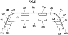
- a hollow closed cross-sectional structure 35 is configured by the first member 31 and the second member 32 as shown in Figure 4 and Figure 5 .
- illustration of the second front wall part 32c bonded to the first front wall part 31c is omitted.
- the upper cross member 30 required to have high bending rigidity and torsional rigidity has the hollow closed cross-sectional structure 35.
- the left and right longitudinal frames 21, 22 lower in required strength than the upper cross member 30 are formed of a ]-shaped open cross-sectional structure opening to the inner side.
- the carbon fiber-reinforced resin material is higher in price than a steel material, it is possible to reduce the use amount of the carbon fiber-reinforced resin material by selecting the hollow closed cross-sectional structure and the open cross-sectional structure for use as needed in the seatback frame structure. As a result, it is possible to hold down material cost.
- the two components of the first member 31 and the second member 32 of the ]-shaped structure opening to the vehicle upward side or the vehicle downward side are overlapped in the vehicle vertical direction and are bonded by an adhesive agent to form the hollow closed cross-sectional structure 35. Therefore, the two components are configured such that the separation load does not act on only the bonding section bonded by the adhesive agent. In this case, the separation load and a compression load act on the bonding section of the first member 31 and the second member 32. Therefore, it is possible to suppress the separation load to the bonding section formed by the adhesive agent. As a result, the breakage of the bonding section can be suppressed.
- each member of the first member 31, the second member 32 and the like is formed in a simple drawn shape, degree of difficulty in manufacture is low. Therefore, in the construction method of the carbon fiber-reinforced resin material, the manufacture using RTM or press affordable in price and short in tact time is made possible.
- the right joining part 41 in which the first member 31 and the right longitudinal frame 21 are bonded is bonded.
- the right side surface part 31b of the first member 31 in the seat width direction is bonded to the longitudinal wall part 21a in a state of being inserted in the inner side of the inner opening part of the right longitudinal frame 21.
- the front surface (the outer surface) of the first front wall part 31c disposed in the front end of the right side surface part 31b in the seat width direction is bonded by an adhesive agent in a state of abutting on the rear surface (the inner surface) of the front flange part 21b in the right longitudinal frame 21.
- the rear surface (the outer surface) of the first rear wall part 31d disposed in the rear end of the right side surface part 31b in the seat width direction is bonded by an adhesive agent in a state of abutting on the front surface (the inner surface) of the rear flange part 21c in the right longitudinal frame 21.
- the left side surface part 31b of the first member 31 in the seat width direction is bonded to the longitudinal wall part 22a in a state of being inserted in the inner side of the opening part of the left longitudinal frame 22.
- the front surface (the outer surface) of the first front wall part 31c disposed in the front end of the left side surface part 31b in the seat width direction is bonded by an adhesive agent in a state of abutting on the rear surface (the inner surface) of the front flange part 22b in the left longitudinal frame 22.
- the rear surface (the outer surface) of the first rear wall part 31d disposed in the rear end of the left side surface part 31b in the seat width direction is bonded by an adhesive agent in a state of abutting on the front surface (the inner surface) of the rear flange part 22c in the left longitudinal frame 22.
- the left and right longitudinal frames 21, 22 are arranged in the first member 31 of the upper cross member 30 in the outer side of the seat width direction. Thereby, for example, when a rear collision load is input to the upper cross member 30, the left and right longitudinal frames 21, 22 can suppress deformation of the upper cross member 30 in the load direction. As a result, the rear collision load can be borne by the joining parts 41, 42 by the adhesive agent, and can be further borne by the longitudinal frames 21, 22 as well on the structure.
- the section bearing the rear collision load is borne only by the adhesion strength of the left and right joining parts 41, 42 formed by the adhesive agent. Meanwhile, the strength against the rear collision load improves with the configuration as described above.
- the coated area of the adhesive agent is small, the use amount of the adhesive agent can be suppressed, leading to a reduction in cost.
- the adhesive agent is applied primarily to the end part of the member, the workability is also excellent. Further, it is possible to reduce a size of tools for fixation or the like.
- the vehicle vertical positions of the left and right joining parts 41, 42 in which the first member 31 and the left and right longitudinal frames 21, 22 are bonded are arranged closer to the vehicle downward side than the vehicle vertical position of the hollow closed cross-sectional structure 35 configured by the first member 31 and the second member 32 and closer to the vehicle upward side than the vehicle vertical position P in which the seat front-back direction width in the left and right longitudinal frames 21, 22 is the smallest. That is, the joining parts 41, 42 are arranged in an area in a range shown in X of Figure 4 . In Figure 4 , the position of the left joining part 42 is shown, but the right joining part 41 is also similar thereto.
- two upper through holes 31g are formed on the upper surface part 31a of the first member 31.
- the through holes are arranged to be spaced in the seat width direction.
- two lower through holes 32g are formed also on the lower surface part 32a of the second member 32.
- the lower through holes 32g are arranged to be spaced in the seat width direction.
- the right upper through hole 31g in the upper surface part 31a and the right lower through hole 32g in the lower surface part 32a are communicated with each other in the vehicle vertical direction when the first member 31 and the second member 32 are assembled.
- the left upper through hole 31g in the upper surface part 31a and the left lower through hole 32g in the lower surface part 32a are also communicated with each other.
- the headrest frame 4a is inserted in the right upper through hole 31g and the right lower through hole 32g communicating in the upper-lower side and in the left upper through hole 31g and the left lower through hole 32g communicating in the upper-lower side.
- the four through holes 31g, 32g can be used as positioning holes at the time of assembling the upper cross member 30. For example, by inserting a round bar member in the through holes 31g, 32g communicating in the upper-lower side, the positional adjustment at the time of bonding the first member 31 and the second member 32 is easy.
- an upper end 32h of the side wall part 32b in the second member 32 is caused to abut on the backside of the side surface part 31b in the first member 31, but this is not limited thereto, and it may be bonded by an adhesive agent.
- the first front wall part 31c and the second front wall part 32c may be arranged reversely in the front and back for bonding. That is, the second front wall part 32 may be bonded to the front surface of the first front wall part 31c. The same can be applied to the first rear wall part 31d and the second rear wall part 32d as well.
- the bond between the upper cross member 30, and the left and right longitudinal frames 21, 22 is not limited to the bond by the adhesive agent, and may be a mechanical join (rivet join or caulked join).
- the longitudinal frames 21, 22 are not limited to a fiber-reinforced resin material, and they may be of a metallic material, a non-ferrous metal material, or other resin materials.
Landscapes
- Engineering & Computer Science (AREA)
- Aviation & Aerospace Engineering (AREA)
- Transportation (AREA)
- Mechanical Engineering (AREA)
- Seats For Vehicles (AREA)
Claims (2)
- Structure d'armature de dossier de siège de véhicule comprenant :deux armatures latérales (21, 22) qui s'étendent dans une direction verticale de véhicule et sont agencées pour être espacées dans une direction de largeur de siège ; etune traverse supérieure (30) qui s'étend dans la direction de largeur de siège et raccorde des parties supérieures des armatures latérales (21, 22) respectives, dans laquellela traverse supérieure (30) comporte un premier organe (31) s'étendant dans la direction de largeur de siège, et un second organe (32) disposé sous le premier organe (31) et s'étendant dans la direction de largeur de siège,le premier organe (31) a une partie inférieure qui est pourvue d'une partie d'ouverture vers le bas s'étendant dans la direction de largeur de siège et s'ouvrant vers le côté vers le bas de véhicule,le second organe (32) a une partie supérieure qui est pourvue d'une partie d'ouverture vers le haut s'étendant dans la direction de largeur de siège et s'ouvrant vers le côté vers le haut de véhicule, etla traverse supérieure (30) a une structure en coupe fermée configurée par la partie d'ouverture vers le bas du premier organe (31) et la partie d'ouverture vers le haut du second organe (32),caractérisée en ce que les deux armatures latérales (21, 22) sont en résine et une position verticale de véhicule d'une partie de jonction (41, 42) entre la traverse supérieure (30) et l'armature latérale (21, 22) est disposée plus près du côté vers le bas de véhicule que la position verticale de véhicule de la structure en coupe fermée de la traverse supérieure (30) et plus près du côté vers le haut de véhicule que la position verticale de véhicule dans laquelle une largeur de direction avant-arrière de l'armature latérale (21, 22) est la plus petite.
- Structure d'armature de dossier de siège de véhicule selon la revendication 1, dans laquelle
l'armature latérale (21, 22) est pourvue d'une partie d'ouverture intérieure dans le côté intérieur dans la direction de largeur de siège, la partie d'ouverture intérieure s'étendant dans la direction verticale de véhicule et s'ouvrant vers le côté intérieur dans la direction de largeur de siège,
le second organe (32) est lié dans un état où il est accueilli dans le côté intérieur de la partie d'ouverture vers le bas du premier organe (31), et
le premier organe (31) a une partie d'extrémité de direction de largeur de siège qui est liée dans un état où elle est insérée dans le côté intérieur de la partie d'ouverture intérieure de l'armature latérale (21, 22).
Applications Claiming Priority (2)
| Application Number | Priority Date | Filing Date | Title |
|---|---|---|---|
| JP2017010472A JP6760857B2 (ja) | 2017-01-24 | 2017-01-24 | 車両用シートバックフレーム構造 |
| PCT/JP2018/001704 WO2018139385A1 (fr) | 2017-01-24 | 2018-01-22 | Structure de cadre de dossier de siège de véhicule |
Publications (3)
| Publication Number | Publication Date |
|---|---|
| EP3575145A1 EP3575145A1 (fr) | 2019-12-04 |
| EP3575145A4 EP3575145A4 (fr) | 2020-01-01 |
| EP3575145B1 true EP3575145B1 (fr) | 2021-03-24 |
Family
ID=62978429
Family Applications (1)
| Application Number | Title | Priority Date | Filing Date |
|---|---|---|---|
| EP18745414.5A Active EP3575145B1 (fr) | 2017-01-24 | 2018-01-22 | Structure de cadre de dossier de siège de véhicule |
Country Status (4)
| Country | Link |
|---|---|
| EP (1) | EP3575145B1 (fr) |
| JP (1) | JP6760857B2 (fr) |
| CN (1) | CN110167794B (fr) |
| WO (1) | WO2018139385A1 (fr) |
Families Citing this family (3)
| Publication number | Priority date | Publication date | Assignee | Title |
|---|---|---|---|---|
| JP7062526B2 (ja) * | 2018-06-07 | 2022-05-06 | 株式会社タチエス | 車両用シート |
| CN113442806A (zh) * | 2021-08-04 | 2021-09-28 | 上海国琻汽车科技有限公司 | 靠背骨架结构及包括该靠背骨架结构的座椅 |
| US20250178497A1 (en) | 2023-12-04 | 2025-06-05 | GM Global Technology Operations LLC | Vehicle seat back frame member with adjustable stiffness system and method |
Family Cites Families (11)
| Publication number | Priority date | Publication date | Assignee | Title |
|---|---|---|---|---|
| FR2594760B1 (fr) * | 1986-02-21 | 1989-11-10 | Renault | Armature de siege a modules de construction assembles |
| JPH08214987A (ja) * | 1995-02-13 | 1996-08-27 | Ikeda Bussan Co Ltd | 座席のフレーム構造 |
| JP2004016710A (ja) * | 2002-06-20 | 2004-01-22 | Shigeru Co Ltd | 車両用シートバック |
| US7066552B2 (en) * | 2003-03-31 | 2006-06-27 | Ts Tech Co., Ltd. | Seat back frame for vehicle seat |
| JP2008067722A (ja) * | 2003-03-31 | 2008-03-27 | T S Tec Kk | 超高張力鋼板製自動車用シートバックフレーム |
| DE202006006834U1 (de) * | 2006-04-28 | 2006-07-27 | Faurecia Autositze Gmbh & Co. Kg | Rückenlehnenrahmen eines Kraftfahrzeugsitzes |
| JP2010046162A (ja) * | 2008-08-20 | 2010-03-04 | Nhk Spring Co Ltd | 車両用シートバックのフレーム構造及び該構造を有する車両用シートバック |
| PL2366584T3 (pl) * | 2010-03-19 | 2013-02-28 | Ruspa Officine S P A | Siedzenie pojazdu |
| WO2013021484A1 (fr) * | 2011-08-10 | 2013-02-14 | ジョンソン コントロールズ テクノロジー カンパニ- | Cadre de dossier de siège pour véhicule |
| JP6004863B2 (ja) | 2012-09-24 | 2016-10-12 | テイ・エス テック株式会社 | シートのフレーム |
| JP6521660B2 (ja) * | 2015-02-17 | 2019-05-29 | テイ・エス テック株式会社 | シートフレーム及び車両用シート |
-
2017
- 2017-01-24 JP JP2017010472A patent/JP6760857B2/ja active Active
-
2018
- 2018-01-22 EP EP18745414.5A patent/EP3575145B1/fr active Active
- 2018-01-22 WO PCT/JP2018/001704 patent/WO2018139385A1/fr not_active Ceased
- 2018-01-22 CN CN201880006379.3A patent/CN110167794B/zh active Active
Non-Patent Citations (1)
| Title |
|---|
| None * |
Also Published As
| Publication number | Publication date |
|---|---|
| JP2018118585A (ja) | 2018-08-02 |
| CN110167794B (zh) | 2021-07-06 |
| CN110167794A (zh) | 2019-08-23 |
| JP6760857B2 (ja) | 2020-09-23 |
| EP3575145A1 (fr) | 2019-12-04 |
| WO2018139385A1 (fr) | 2018-08-02 |
| EP3575145A4 (fr) | 2020-01-01 |
Similar Documents
| Publication | Publication Date | Title |
|---|---|---|
| CN102131671B (zh) | 交通工具座椅框架和制造方法 | |
| CN101677691B (zh) | 拼焊座椅及部件 | |
| US9108554B2 (en) | Structural element for a vehicle seat | |
| US8152223B2 (en) | Sidewall for a motor vehicle | |
| CN108778909B (zh) | 车体下部构造 | |
| US9238428B2 (en) | Back frame for vehicle seat | |
| EP2391526B1 (fr) | Structures de siège et procédés de création de structures de siège | |
| US9096152B2 (en) | Inclination adjuster for vehicle seats | |
| EP2749450A1 (fr) | Structure de cadre pour dossier de siège | |
| CN102046418B (zh) | 结构部件、包括靠背的车辆座椅及制造结构部件或靠背的方法 | |
| EP3575145B1 (fr) | Structure de cadre de dossier de siège de véhicule | |
| JP5641662B2 (ja) | 車両シャーシ | |
| US12606245B2 (en) | Vehicle rear structure | |
| JP2014502583A (ja) | 一部品シートバックフレーム及び製造方法 | |
| US9376045B2 (en) | Vehicle seat | |
| EP3575143B1 (fr) | Structure de siège de véhicule | |
| US20050200184A1 (en) | Mechanically locked recliners | |
| US20080252131A1 (en) | Automotive vehicle seat back and method of making same | |
| TR201908739T4 (tr) | Taşıt şasisi yapıları. | |
| JP6973291B2 (ja) | 乗物用シート | |
| CN111907601A (zh) | 中柱制造方法 | |
| US20240123876A1 (en) | Conveyance seat | |
| US20240270135A1 (en) | Conveyance seat | |
| JP2006081676A (ja) | 車両のシートバックフレーム構造 | |
| JP5813578B2 (ja) | シートフレーム及びその製造方法 |
Legal Events
| Date | Code | Title | Description |
|---|---|---|---|
| STAA | Information on the status of an ep patent application or granted ep patent |
Free format text: STATUS: THE INTERNATIONAL PUBLICATION HAS BEEN MADE |
|
| PUAI | Public reference made under article 153(3) epc to a published international application that has entered the european phase |
Free format text: ORIGINAL CODE: 0009012 |
|
| STAA | Information on the status of an ep patent application or granted ep patent |
Free format text: STATUS: REQUEST FOR EXAMINATION WAS MADE |
|
| 17P | Request for examination filed |
Effective date: 20190604 |
|
| AK | Designated contracting states |
Kind code of ref document: A1 Designated state(s): AL AT BE BG CH CY CZ DE DK EE ES FI FR GB GR HR HU IE IS IT LI LT LU LV MC MK MT NL NO PL PT RO RS SE SI SK SM TR |
|
| AX | Request for extension of the european patent |
Extension state: BA ME |
|
| A4 | Supplementary search report drawn up and despatched |
Effective date: 20191129 |
|
| RIC1 | Information provided on ipc code assigned before grant |
Ipc: B60N 2/64 20060101ALI20191125BHEP Ipc: A47C 7/40 20060101ALI20191125BHEP Ipc: B60N 2/427 20060101ALI20191125BHEP Ipc: B60N 2/90 20180101ALI20191125BHEP Ipc: B60N 2/68 20060101AFI20191125BHEP |
|
| DAV | Request for validation of the european patent (deleted) | ||
| DAX | Request for extension of the european patent (deleted) | ||
| GRAP | Despatch of communication of intention to grant a patent |
Free format text: ORIGINAL CODE: EPIDOSNIGR1 |
|
| STAA | Information on the status of an ep patent application or granted ep patent |
Free format text: STATUS: GRANT OF PATENT IS INTENDED |
|
| INTG | Intention to grant announced |
Effective date: 20201215 |
|
| GRAS | Grant fee paid |
Free format text: ORIGINAL CODE: EPIDOSNIGR3 |
|
| GRAA | (expected) grant |
Free format text: ORIGINAL CODE: 0009210 |
|
| STAA | Information on the status of an ep patent application or granted ep patent |
Free format text: STATUS: THE PATENT HAS BEEN GRANTED |
|
| AK | Designated contracting states |
Kind code of ref document: B1 Designated state(s): AL AT BE BG CH CY CZ DE DK EE ES FI FR GB GR HR HU IE IS IT LI LT LU LV MC MK MT NL NO PL PT RO RS SE SI SK SM TR |
|
| REG | Reference to a national code |
Ref country code: GB Ref legal event code: FG4D |
|
| REG | Reference to a national code |
Ref country code: CH Ref legal event code: EP |
|
| REG | Reference to a national code |
Ref country code: IE Ref legal event code: FG4D |
|
| REG | Reference to a national code |
Ref country code: AT Ref legal event code: REF Ref document number: 1374164 Country of ref document: AT Kind code of ref document: T Effective date: 20210415 Ref country code: DE Ref legal event code: R096 Ref document number: 602018014456 Country of ref document: DE |
|
| REG | Reference to a national code |
Ref country code: LT Ref legal event code: MG9D |
|
| PG25 | Lapsed in a contracting state [announced via postgrant information from national office to epo] |
Ref country code: NO Free format text: LAPSE BECAUSE OF FAILURE TO SUBMIT A TRANSLATION OF THE DESCRIPTION OR TO PAY THE FEE WITHIN THE PRESCRIBED TIME-LIMIT Effective date: 20210624 Ref country code: BG Free format text: LAPSE BECAUSE OF FAILURE TO SUBMIT A TRANSLATION OF THE DESCRIPTION OR TO PAY THE FEE WITHIN THE PRESCRIBED TIME-LIMIT Effective date: 20210624 Ref country code: GR Free format text: LAPSE BECAUSE OF FAILURE TO SUBMIT A TRANSLATION OF THE DESCRIPTION OR TO PAY THE FEE WITHIN THE PRESCRIBED TIME-LIMIT Effective date: 20210625 Ref country code: FI Free format text: LAPSE BECAUSE OF FAILURE TO SUBMIT A TRANSLATION OF THE DESCRIPTION OR TO PAY THE FEE WITHIN THE PRESCRIBED TIME-LIMIT Effective date: 20210324 Ref country code: HR Free format text: LAPSE BECAUSE OF FAILURE TO SUBMIT A TRANSLATION OF THE DESCRIPTION OR TO PAY THE FEE WITHIN THE PRESCRIBED TIME-LIMIT Effective date: 20210324 |
|
| PG25 | Lapsed in a contracting state [announced via postgrant information from national office to epo] |
Ref country code: SE Free format text: LAPSE BECAUSE OF FAILURE TO SUBMIT A TRANSLATION OF THE DESCRIPTION OR TO PAY THE FEE WITHIN THE PRESCRIBED TIME-LIMIT Effective date: 20210324 Ref country code: LV Free format text: LAPSE BECAUSE OF FAILURE TO SUBMIT A TRANSLATION OF THE DESCRIPTION OR TO PAY THE FEE WITHIN THE PRESCRIBED TIME-LIMIT Effective date: 20210324 Ref country code: RS Free format text: LAPSE BECAUSE OF FAILURE TO SUBMIT A TRANSLATION OF THE DESCRIPTION OR TO PAY THE FEE WITHIN THE PRESCRIBED TIME-LIMIT Effective date: 20210324 |
|
| REG | Reference to a national code |
Ref country code: NL Ref legal event code: MP Effective date: 20210324 |
|
| REG | Reference to a national code |
Ref country code: AT Ref legal event code: MK05 Ref document number: 1374164 Country of ref document: AT Kind code of ref document: T Effective date: 20210324 |
|
| PG25 | Lapsed in a contracting state [announced via postgrant information from national office to epo] |
Ref country code: NL Free format text: LAPSE BECAUSE OF FAILURE TO SUBMIT A TRANSLATION OF THE DESCRIPTION OR TO PAY THE FEE WITHIN THE PRESCRIBED TIME-LIMIT Effective date: 20210324 |
|
| PG25 | Lapsed in a contracting state [announced via postgrant information from national office to epo] |
Ref country code: CZ Free format text: LAPSE BECAUSE OF FAILURE TO SUBMIT A TRANSLATION OF THE DESCRIPTION OR TO PAY THE FEE WITHIN THE PRESCRIBED TIME-LIMIT Effective date: 20210324 Ref country code: EE Free format text: LAPSE BECAUSE OF FAILURE TO SUBMIT A TRANSLATION OF THE DESCRIPTION OR TO PAY THE FEE WITHIN THE PRESCRIBED TIME-LIMIT Effective date: 20210324 Ref country code: LT Free format text: LAPSE BECAUSE OF FAILURE TO SUBMIT A TRANSLATION OF THE DESCRIPTION OR TO PAY THE FEE WITHIN THE PRESCRIBED TIME-LIMIT Effective date: 20210324 Ref country code: SM Free format text: LAPSE BECAUSE OF FAILURE TO SUBMIT A TRANSLATION OF THE DESCRIPTION OR TO PAY THE FEE WITHIN THE PRESCRIBED TIME-LIMIT Effective date: 20210324 Ref country code: AT Free format text: LAPSE BECAUSE OF FAILURE TO SUBMIT A TRANSLATION OF THE DESCRIPTION OR TO PAY THE FEE WITHIN THE PRESCRIBED TIME-LIMIT Effective date: 20210324 |
|
| PG25 | Lapsed in a contracting state [announced via postgrant information from national office to epo] |
Ref country code: IS Free format text: LAPSE BECAUSE OF FAILURE TO SUBMIT A TRANSLATION OF THE DESCRIPTION OR TO PAY THE FEE WITHIN THE PRESCRIBED TIME-LIMIT Effective date: 20210724 Ref country code: PL Free format text: LAPSE BECAUSE OF FAILURE TO SUBMIT A TRANSLATION OF THE DESCRIPTION OR TO PAY THE FEE WITHIN THE PRESCRIBED TIME-LIMIT Effective date: 20210324 Ref country code: RO Free format text: LAPSE BECAUSE OF FAILURE TO SUBMIT A TRANSLATION OF THE DESCRIPTION OR TO PAY THE FEE WITHIN THE PRESCRIBED TIME-LIMIT Effective date: 20210324 Ref country code: PT Free format text: LAPSE BECAUSE OF FAILURE TO SUBMIT A TRANSLATION OF THE DESCRIPTION OR TO PAY THE FEE WITHIN THE PRESCRIBED TIME-LIMIT Effective date: 20210726 Ref country code: SK Free format text: LAPSE BECAUSE OF FAILURE TO SUBMIT A TRANSLATION OF THE DESCRIPTION OR TO PAY THE FEE WITHIN THE PRESCRIBED TIME-LIMIT Effective date: 20210324 |
|
| REG | Reference to a national code |
Ref country code: DE Ref legal event code: R097 Ref document number: 602018014456 Country of ref document: DE |
|
| PG25 | Lapsed in a contracting state [announced via postgrant information from national office to epo] |
Ref country code: AL Free format text: LAPSE BECAUSE OF FAILURE TO SUBMIT A TRANSLATION OF THE DESCRIPTION OR TO PAY THE FEE WITHIN THE PRESCRIBED TIME-LIMIT Effective date: 20210324 Ref country code: DK Free format text: LAPSE BECAUSE OF FAILURE TO SUBMIT A TRANSLATION OF THE DESCRIPTION OR TO PAY THE FEE WITHIN THE PRESCRIBED TIME-LIMIT Effective date: 20210324 Ref country code: ES Free format text: LAPSE BECAUSE OF FAILURE TO SUBMIT A TRANSLATION OF THE DESCRIPTION OR TO PAY THE FEE WITHIN THE PRESCRIBED TIME-LIMIT Effective date: 20210324 |
|
| PLBE | No opposition filed within time limit |
Free format text: ORIGINAL CODE: 0009261 |
|
| STAA | Information on the status of an ep patent application or granted ep patent |
Free format text: STATUS: NO OPPOSITION FILED WITHIN TIME LIMIT |
|
| PG25 | Lapsed in a contracting state [announced via postgrant information from national office to epo] |
Ref country code: SI Free format text: LAPSE BECAUSE OF FAILURE TO SUBMIT A TRANSLATION OF THE DESCRIPTION OR TO PAY THE FEE WITHIN THE PRESCRIBED TIME-LIMIT Effective date: 20210324 |
|
| 26N | No opposition filed |
Effective date: 20220104 |
|
| PG25 | Lapsed in a contracting state [announced via postgrant information from national office to epo] |
Ref country code: IS Free format text: LAPSE BECAUSE OF FAILURE TO SUBMIT A TRANSLATION OF THE DESCRIPTION OR TO PAY THE FEE WITHIN THE PRESCRIBED TIME-LIMIT Effective date: 20210724 |
|
| PG25 | Lapsed in a contracting state [announced via postgrant information from national office to epo] |
Ref country code: MC Free format text: LAPSE BECAUSE OF FAILURE TO SUBMIT A TRANSLATION OF THE DESCRIPTION OR TO PAY THE FEE WITHIN THE PRESCRIBED TIME-LIMIT Effective date: 20210324 |
|
| REG | Reference to a national code |
Ref country code: CH Ref legal event code: PL |
|
| GBPC | Gb: european patent ceased through non-payment of renewal fee |
Effective date: 20220122 |
|
| REG | Reference to a national code |
Ref country code: BE Ref legal event code: MM Effective date: 20220131 |
|
| PG25 | Lapsed in a contracting state [announced via postgrant information from national office to epo] |
Ref country code: LU Free format text: LAPSE BECAUSE OF NON-PAYMENT OF DUE FEES Effective date: 20220122 Ref country code: GB Free format text: LAPSE BECAUSE OF NON-PAYMENT OF DUE FEES Effective date: 20220122 |
|
| PG25 | Lapsed in a contracting state [announced via postgrant information from national office to epo] |
Ref country code: BE Free format text: LAPSE BECAUSE OF NON-PAYMENT OF DUE FEES Effective date: 20220131 |
|
| PG25 | Lapsed in a contracting state [announced via postgrant information from national office to epo] |
Ref country code: LI Free format text: LAPSE BECAUSE OF NON-PAYMENT OF DUE FEES Effective date: 20220131 Ref country code: CH Free format text: LAPSE BECAUSE OF NON-PAYMENT OF DUE FEES Effective date: 20220131 |
|
| PG25 | Lapsed in a contracting state [announced via postgrant information from national office to epo] |
Ref country code: IT Free format text: LAPSE BECAUSE OF FAILURE TO SUBMIT A TRANSLATION OF THE DESCRIPTION OR TO PAY THE FEE WITHIN THE PRESCRIBED TIME-LIMIT Effective date: 20210324 Ref country code: IE Free format text: LAPSE BECAUSE OF NON-PAYMENT OF DUE FEES Effective date: 20220122 |
|
| PG25 | Lapsed in a contracting state [announced via postgrant information from national office to epo] |
Ref country code: MK Free format text: LAPSE BECAUSE OF FAILURE TO SUBMIT A TRANSLATION OF THE DESCRIPTION OR TO PAY THE FEE WITHIN THE PRESCRIBED TIME-LIMIT Effective date: 20210324 Ref country code: CY Free format text: LAPSE BECAUSE OF FAILURE TO SUBMIT A TRANSLATION OF THE DESCRIPTION OR TO PAY THE FEE WITHIN THE PRESCRIBED TIME-LIMIT Effective date: 20210324 |
|
| PG25 | Lapsed in a contracting state [announced via postgrant information from national office to epo] |
Ref country code: HU Free format text: LAPSE BECAUSE OF FAILURE TO SUBMIT A TRANSLATION OF THE DESCRIPTION OR TO PAY THE FEE WITHIN THE PRESCRIBED TIME-LIMIT; INVALID AB INITIO Effective date: 20180122 |
|
| PG25 | Lapsed in a contracting state [announced via postgrant information from national office to epo] |
Ref country code: TR Free format text: LAPSE BECAUSE OF FAILURE TO SUBMIT A TRANSLATION OF THE DESCRIPTION OR TO PAY THE FEE WITHIN THE PRESCRIBED TIME-LIMIT Effective date: 20210324 |
|
| PG25 | Lapsed in a contracting state [announced via postgrant information from national office to epo] |
Ref country code: MT Free format text: LAPSE BECAUSE OF FAILURE TO SUBMIT A TRANSLATION OF THE DESCRIPTION OR TO PAY THE FEE WITHIN THE PRESCRIBED TIME-LIMIT Effective date: 20210324 |
|
| PGFP | Annual fee paid to national office [announced via postgrant information from national office to epo] |
Ref country code: FR Payment date: 20251128 Year of fee payment: 9 |
|
| PGFP | Annual fee paid to national office [announced via postgrant information from national office to epo] |
Ref country code: DE Payment date: 20251203 Year of fee payment: 9 |