EP3575189A1 - Pied milieu pour une carrosserie de véhicule ainsi que carrosserie de véhicule pourvue d'un tel pied milieu - Google Patents
Pied milieu pour une carrosserie de véhicule ainsi que carrosserie de véhicule pourvue d'un tel pied milieu Download PDFInfo
- Publication number
- EP3575189A1 EP3575189A1 EP19176432.3A EP19176432A EP3575189A1 EP 3575189 A1 EP3575189 A1 EP 3575189A1 EP 19176432 A EP19176432 A EP 19176432A EP 3575189 A1 EP3575189 A1 EP 3575189A1
- Authority
- EP
- European Patent Office
- Prior art keywords
- pillar
- fiber composite
- composite component
- metal
- force introduction
- Prior art date
- Legal status (The legal status is an assumption and is not a legal conclusion. Google has not performed a legal analysis and makes no representation as to the accuracy of the status listed.)
- Granted
Links
Images


Classifications
-
- B—PERFORMING OPERATIONS; TRANSPORTING
- B62—LAND VEHICLES FOR TRAVELLING OTHERWISE THAN ON RAILS
- B62D—MOTOR VEHICLES; TRAILERS
- B62D21/00—Understructures, i.e. chassis frame on which a vehicle body may be mounted
- B62D21/15—Understructures, i.e. chassis frame on which a vehicle body may be mounted having impact absorbing means, e.g. a frame designed to permanently or temporarily change shape or dimension upon impact with another body
- B62D21/157—Understructures, i.e. chassis frame on which a vehicle body may be mounted having impact absorbing means, e.g. a frame designed to permanently or temporarily change shape or dimension upon impact with another body for side impacts
-
- B—PERFORMING OPERATIONS; TRANSPORTING
- B62—LAND VEHICLES FOR TRAVELLING OTHERWISE THAN ON RAILS
- B62D—MOTOR VEHICLES; TRAILERS
- B62D25/00—Superstructure or monocoque structure sub-units; Parts or details thereof not otherwise provided for
- B62D25/04—Door pillars ; windshield pillars
-
- B—PERFORMING OPERATIONS; TRANSPORTING
- B62—LAND VEHICLES FOR TRAVELLING OTHERWISE THAN ON RAILS
- B62D—MOTOR VEHICLES; TRAILERS
- B62D25/00—Superstructure or monocoque structure sub-units; Parts or details thereof not otherwise provided for
- B62D25/06—Fixed roofs
-
- B—PERFORMING OPERATIONS; TRANSPORTING
- B62—LAND VEHICLES FOR TRAVELLING OTHERWISE THAN ON RAILS
- B62D—MOTOR VEHICLES; TRAILERS
- B62D29/00—Superstructures, understructures, or sub-units thereof, characterised by the material thereof
- B62D29/001—Superstructures, understructures, or sub-units thereof, characterised by the material thereof characterised by combining metal and synthetic material
-
- B—PERFORMING OPERATIONS; TRANSPORTING
- B62—LAND VEHICLES FOR TRAVELLING OTHERWISE THAN ON RAILS
- B62D—MOTOR VEHICLES; TRAILERS
- B62D29/00—Superstructures, understructures, or sub-units thereof, characterised by the material thereof
- B62D29/001—Superstructures, understructures, or sub-units thereof, characterised by the material thereof characterised by combining metal and synthetic material
- B62D29/004—Superstructures, understructures, or sub-units thereof, characterised by the material thereof characterised by combining metal and synthetic material the metal being over-moulded by the synthetic material, e.g. in a mould
Definitions
- the present invention relates to a B-pillar for a motor vehicle body, which extends along a longitudinal axis and an upper metal portion for connecting the B-pillar to a roof area of the body and a lower metal portion for connecting the B-pillar to a sill area of the body and a Fiber composite component comprises. Furthermore, the present invention relates to a motor vehicle body with such a B-pillar.
- a B-pillar that has a metallic body reinforced with a fiber composite in areas of localized stress maxima.
- the load acting on the B-pillar thus contributes to a multilayer composite of metal and fiber composite material.
- the DE 10 2006 027 546 A1 shows a multi-shell B-pillar made of sheet metal parts, which is locally reinforced in the middle region of the B-pillar to protect the occupants in a side impact with an impact protection reinforcing member.
- the reinforcement part consists of a fiber composite material.
- the present invention has for its object to provide a weight-reduced B-pillar that meets demanding crash load cases.
- the object is also to provide a weight-reduced vehicle body that meets demanding crash load cases.
- a solution consists in a B-pillar of the type mentioned above in that the upper metal section has an upper force introduction region and the lower metal section has a lower force introduction region axially spaced from the upper force introduction region, wherein the upper force introduction region and the lower force introduction region are embedded in the fiber composite component.
- the B-pillar is a load-bearing vehicle pillar of a motor vehicle body.
- a built-in state it is meant that state in which the functional B-pillar is installed in the body between the roof area and the sill area.
- Terms such as “bottom,” “top,” or “center” represent spatial information regarding the B-pillar when the body is installed.
- the length of the B-pillar corresponds to the length of the course of a centerline of the B-pillar extending from a lower edge of the B-pillar to an upper edge of the B-pillar.
- the center line is a straight longitudinal axis of the B-pillar, wherein the center line can also be bent in curved course of the B-pillar.
- the B-pillar is a hybrid metal fiber composite column in integral construction. It is advantageous that the hybrid B-pillar can be integrated into the metallic vehicle bodywork by means of conventional joining techniques, for example by using conventional welding methods. A further advantage is that areas of the B-pillar, which do not serve the connection to components of the body, can be substituted by the lighter compared to metallic materials fiber composite component. Thus, it is provided that the fiber composite component areas in which the metallic material is recessed, in particular completely fills. It follows that the fiber composite component is not used in the form of local patches for reinforcing a metal body of the B-pillar. Rather, a material duplication that is by overlaying metal sections with the fiber composite component results only to the extent necessary to ensure a permanent connection between the two connection partners, fiber composite component and metal section in the respective force introduction region.
- the plastic matrix of the fiber composite component serves as an adhesive which inextricably connects the upper metal portion and the lower metal portion with the fiber composite component.
- Embedded means that the respective metal section, viewed in section through the B-pillar, is c-shaped surrounded by the fiber composite component. Thus, the fiber composite component abuts three sides on the respective metal portion.
- the fiber composite component comprises the plastic matrix and the fibers bound in the matrix.
- the fibers within the fiber composite component take over the power transmission and the matrix fills interstices and introduces the external forces into the fibers.
- the plastic matrix may be a thermoplastic matrix or a thermosetting matrix.
- the fibers may include, for example, carbon and / or glass and / or aramid fiber.
- connection of the metal sections with the fiber composite component takes place before the curing or solidification of the matrix and thus during the production of the fiber composite component.
- the fiber composite material can be connected by hand, semi-mechanically or mechanically with the metal sections, for example by a laminating, fiber spraying, pressing or injection method or by another method suitable for connecting metal with fiber composite material.
- the fiber composite component and the metal sections are permanently connected to one another and form an integral hybrid component in the form of the functional B-pillar.
- insoluble means that the fiber composite component immovably adheres to the metal sections. If there is a detachment of the fiber composite component of the metal sections, for example due to an accidental side impact, the B-pillar is destroyed.
- the upper and / or the lower metal sections are / is preferably made of sheet steel.
- the steel sheet may be a particularly high-strength cold-forming steel, for example a dual-phase steel.
- both the upper metal portion and the lower metal portion are made of a cold-formed steel.
- the upper metal portion and / or the lower metal portion may also be made of magnesium or aluminum.
- the upper metal section has an upper end edge, and / or that the lower metal section has a lower end edge, wherein the fiber composite component with an upper end region over the upper end edge in the upper force introduction region and / or with a lower end portion extends over the lower end edge into the lower force introduction area.
- the fiber composite component with an upper end region over the upper end edge in the upper force introduction region and / or with a lower end portion extends over the lower end edge into the lower force introduction area.
- the resulting recess may be at least partially filled by the fiber composite component to support the load of the B pillar in this area.
- the fiber composite component encompasses the respective metal section, viewed in longitudinal section through the B pillar, in a C shape. This allows a particularly stable integration of the fiber composite component in the power flow of the B-pillar.
- the fiber composite component is formed integrally in itself.
- the fiber composite component performs a structure-carrying function within the B-pillar.
- the load acting on the installed B-pillar along a longitudinal section of the B-pillar, which is defined between the upper metal section and the lower metal section can be transferred to more than 50% by the fiber composite component integrated in the force flow of the B-pillar be worn.
- the fiber composite component may extend over at least 0.25 times a total length of the B-pillar, in particular between 50% and 90% of the total length be the B-pillar. Furthermore, a distance between the upper end edge and the lower end edge may be at least 25% of the total length of the B pillar and / or a maximum of 95% of the total length of the B pillar. Another advantage is that the fiber composite component is thus arranged in a central region of the B-pillar, which is designed to protect the occupants usually high strength.
- the fiber composite component has a lower elongation at break compared to the metallic material of the metal sections, but is elastic to load load, for example in a side impact, to some degree and can yield accordingly. As long as the elongation at break of the fiber composite component is not exceeded, this returns after load entry back to its original shape. This advantageous movement of the fiber composite component can also be referred to as breathing.
- a lower end, in particular a lower end edge of the fiber composite component from a lower end, in particular a lower end edge of the B-pillar with a distance of at least 10 cm, in particular with a distance between 10 cm and 60 cm be spaced.
- the B-pillar can be joined only via the lower metal portion with the sill area of the body in order to use standard joining method for connecting the B-pillar to the metallic sill area.
- Due to the spacing of the fiber composite component from the sill area, a deformation area can be provided by the lower metal section, in particular in a door entry area, which can deform plastically in the event of a crash.
- an upper end in particular an upper end edge of the fiber composite component of an upper end, in particular an upper end edge of the B-pillar with a distance of at least 5 cm, in particular with a Distance between 5 cm and 40 cm, be spaced.
- the B-pillar only over the upper metal portion with the particular metallic Roof area of the body must be joined.
- the upper metal section and the lower metal section are separate sheet-metal shaped parts which are connected to one another exclusively via the fiber composite component.
- the upper metal section is used only for connecting the B-pillar to the roof area of the body and the lower metal section for connecting the B-pillar to the sill area of the body and optionally for providing a deformation zone in the door entry area of the body.
- the two sheet metal parts are spatially spaced apart, so that the supporting function of the B-pillar is taken over in this area of the B-pillar exclusively by the fiber composite component.
- the upper metal section and / or the lower metal section may each have, at least in sections, at least one lateral joining flange for connecting components to the B-pillar to the B-pillar, the at least one lateral joining flange projecting laterally beyond the fiber composite component.
- other components such as a door seal and / or a vehicle outer skin and / or a glass surface can be connected exclusively to the respective metal section, so that also here conventional joining techniques can be used.
- the force introduction region of the upper metal section and / or the force introduction region of the lower metal section may be U-shaped.
- the non-detachable connection between the fiber composite component and the respective metal section is additionally reinforced.
- either the upper or the lower metal section additionally or alternatively to the force introduction areas joining areas which, in contrast to the force introduction regions incorporated in the matrix, rest only on one side on the fiber composite component and are connected to the fiber composite component by means of known joining methods, in particular by means of adhesive, riveting or screwing methods.
- a along the longitudinal axis of the B-pillar extending sheet metal part is present, the upper metal portion and comprises the lower metal portion, wherein the sheet metal part between the upper end edge of the upper force introduction region and the lower end edge of the lower force introduction region has at least one material recess which is at least partially filled by the fiber composite component.
- the sheet metal part preferably extends over the entire length of the B-pillar.
- the at least one recess is designed within the sheet-metal shaped part, so that the force introduction regions, viewed in a sectional plane through the B-pillar, surround the at least one recess, in particular of four sides.
- the cutting plane can run parallel to the longitudinal axis.
- the sheet metal part may at least partially have at least one lateral joining flange for connecting adjacent to the B-pillar components with the B-pillar, wherein the at least one lateral joining flange laterally projects beyond the fiber composite component.
- the sheet metal part serves as the sole connection partner for laterally adjacent to the B-pillar in the installed state components, such as a door seal and / or a vehicle skin and / or a glass surface.
- the lateral joining flanges can be single-layer. That is, one side edge of the fiber composite component is spaced from one side edge of the joint flange such that the joining flange forms a single-layered flange section for connecting adjacent components to the B-pillar.
- the fiber composite part therefore does not have to be connected to the adjacent components.
- the B-pillar has a plurality of, in particular two spaced-apart, outer joining flanges, which extend at least in sections along the longitudinal axis of the B-pillar.
- the at least one joining flange can be recessed specifically in longitudinal sections of the B-pillar in which no connection of adjacent components to the B-pillar used is required.
- laterally outstanding joining flanges made of metal are embedded for the lateral connection of the adjacent components in the fiber composite component. This is especially advantageous when the B-pillar has the two spaced apart sheet metal parts.
- the B-pillar may be U-shaped at least in sections between the upper force introduction region and the lower force introduction region, such that a cavity for receiving vehicle attachment parts is formed on a vehicle interior side of the motor vehicle pillar.
- the U-shaped section may preferably be formed by the fiber composite component.
- the fiber composite component may comprise, at least in sections, two side webs and one middle web connecting the two side webs in a U-shaped manner. Functional parts, such as metal side flanges, can be embedded in the side bars. Due to the overall shell-like configuration, the fiber composite component can on the one hand withstand higher lateral forces acting on the B-pillar, which may arise, for example, in the case of a side impact.
- the resulting cavity vehicle attachment parts such as a striker for a front door and / or a door lock and / or a door hinge and / or a rear door lock and / or a belt reel and / or a belt tensioner, added and if necessary to the Fiber composite component are attached.
- the U-shaped cavity expediently opens in the direction of a passenger compartment of the body, so that the central web of the fiber composite component on the outside, that is on a side facing away from the passenger compartment side of the B-pillar is arranged.
- at least one middle web region of the B pillar is at least partially formed exclusively by the fiber composite component.
- the fiber composite component at least in sections may also have a hat profile.
- the fiber composite component can have two flanges adjoining laterally on the side webs in order to enlarge the connecting surfaces with the respective metal section or the sheet-metal shaped part extending in the longitudinal direction of the B-column, which comprises the two metal sections.
- the fiber composite component can be adapted by axial or multiaxial alignment of the fibers to the customer specifications and the required crash properties.
- the crash behavior can also be adjusted in sections by suitable material selection of the fibers and / or by locally different wall thicknesses, which can be changed by varying the number of fiber layers, for example.
- the concentration of fibers in the fiber composite component can also be varied locally. In principle, it is also possible that the fiber composite component has areas in which no fibers are present.
- At least one metallic reinforcement insert can be embedded in the fiber composite component for local reinforcement of the fiber composite component.
- the at least one reinforcing insert can, viewed in section through the B-pillar, be completely embedded in the fiber composite component.
- the at least one reinforcing insert can be a metallic sheet-metal part, which can be incorporated, for example, by braiding fiber strands in a form-fitting, load-bearing manner into the fabric structure of the surrounding fiber material layers of the fiber composite component.
- the reinforcing insert, as well as the force introduction regions of the metal sections due to its surface texture, respectively roughness and / or a surface coating concept to the matrix be integrated viable.
- the at least one reinforcing insert may be made of a cold or hot formed high, higher or highest strength steel. Furthermore, the at least one reinforcing insert can have a variable thickness or wall thickness. The at least one reinforcing insert can optimally absorb the compressive stresses acting within the fiber composite component in the event of a crash and thus improve the properties of the fiber composite component with respect to tensile strength.
- a blocking or decoupling layer for example of an adhesive, may be provided in each case in order to prevent contact corrosion between the components.
- At least one of the sheet metal parts integrated in the B pillar can have a variable wall thickness over the length of the B pillar.
- the load capacity of the B-pillar can be targeted locally adjusted.
- the B-pillar can be trimmed or adapted to customer-specific required functional goals to different zones of the B-pillar (roof connection, flex zone in the middle / upper column area, deformation zone in the foot area, sill connection), in particular in conjunction with the fiber composite component.
- the sheet thicknesses can vary between 0.7 mm and 4.5 mm.
- the upper metal portion and / or the lower metal portion may have a sheet thickness of 1 mm to 4 mm.
- a metal central section optionally connecting the upper and the lower metal section may have a significantly thinner sheet metal thickness, for example from 0.7 mm to 2 mm, since the main load of the B pillar in this area can be borne by the fiber composite component.
- the fiber composite component between the force introduction regions of the upper and the lower metal portion is not covered by any structural elements of the B-pillar.
- the B-pillar has no inner panel, which is also referred to as a strike plate on.
- the B-pillar may be a so-called "open design". In this way the B-pillar has only one-layer attachment points, namely the upper metal portion and the lower metal portion and the optional lateral Fügeflansche. This simplifies the connection to the body using conventional joining techniques. In principle, it is also possible that the B-pillar has such an inner panel.
- Another solution to the above problem is a vehicle body with two of the above-described B-pillars.
- the body according to the invention provides the same advantages as have been described in connection with the B-pillar according to the invention, so that reference is made here to the above descriptions in abbreviated form. It is understood that all mentioned embodiments of the B-pillar are transferable to the body and vice versa. Overall, the body according to the invention is weight-reduced and can meet demanding crash load cases.
- the outside of the B-pillar can be covered by the vehicle outer skin, which is usually attached to this, in particular the lateral joining flanges of the B-pillar only after completion of the vehicle body.
- the fiber composite component of the B-pillar can also be visible from the outside, at least when the vehicle door is open, even when it is installed.
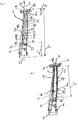
- FIGS. 1 to 9 a B-pillar 1 of a body of a motor vehicle according to a first embodiment of the present invention is shown.
- the B-pillar 1 has an elongated, hollow basic shape and extends along a longitudinal axis X.
- the B-pillar 1 connects a roof area of the body with a sill area of the body.
- the B pillar 1 is a hybrid component which has a sheet-metal shaped part 2 extending along the longitudinal axis X and a fiber composite component 3 which is permanently connected to it.
- the functional B-pillar 1 shown at least Sectionally has a hat-shaped profile.
- the B-pillar 1 may usually have a length L 1 of about 1.30 m to 1.50 m in a conventional passenger car.
- the B-pillar 1 is shown in an unfinished state, in which the fiber composite component 3 has not yet been made.
- the sheet metal part 2 is produced. Only then is the fiber composite component 3, for example, by applying or molding a fiber composite material produced on the sheet metal part 2.
- force introduction regions 18 of the sheet metal part 2 are laminated, for example, in the fiber composite material.
- the fiber composite component 3 is completed, which is then inextricably linked to the sheet metal part 2.
- the sheet metal part 2 and the fiber composite component 3 together form the hybrid B-pillar 1.
- the sheet-metal shaped part 2 can be a cold-formed molded part, which can be produced, for example, from a dual-phase steel sheet.
- the sheet metal part 2 extends over the entire length L 1 of the B-pillar 1 and may over the length L 1 have a variable wall thickness, respectively sheet metal thickness.
- the wall thickness can be adapted according to the customer-specific demanded crash zones.
- the sheet metal part 2 is designed here as a continuous sheet-metal shaped part, which forms the metallic base body of the B-pillar 1.
- the sheet metal part 2 has an upper metal section 4.
- the upper metal portion 4 has a flange-shaped upper connection region 5 with a longitudinally section through the B-pillar 1 considered approximately U-shaped profile, in the installed state of the B-pillar 1, the roof area, in particular a roof rail from the outside embrace.
- the sheet metal part 2 has a lower metal portion 6.
- the lower metal section 6 comprises a lower connection region 7, which in the installed state can surround the sill region from the outside or can be inserted into it. Between the upper metal portion 4 and the lower metal portion 6 extends a central portion 8, the lateral connection of adjacent components, such as a door seal, a glass surface, one in the FIG. 9 simplified motor vehicle outer skin 9 or the like, is used.
- a length L 4 of the upper metal section 4 is less than or equal to 15% of the length L 1 of the B-pillar 1, here about 12% of the length L 1 .
- a length L 6 of the lower metal portion 6 is less than or equal to 25% of the length L 1 of the B-pillar 1, here about 20% of the length L 1 .
- the sheet metal part 2 viewed at least between the upper connection region 5 and the lower connection region 7 in cross section through the B-pillar 1 considered a hat-shaped profile on a passenger interior facing a vehicle inside the B-pillar 1 has a cavity 10 for receiving vehicle attachment parts ,
- the sheet metal part 2 comprises a centrally arranged central web 11, two laterally adjoining side webs 12 and two joining flanges 13 radially adjoining the side webs 12 on the outside.
- the sheet metal part 2 has at least in the region of the central web 11 an upper recess 14 and a lower recess 15, wherein at least one of the recesses 14, 15 may extend over at least a portion of the side webs 12.
- the upper recess 14 is at least partially designed in the upper metal portion 4 and the central portion 8 and may extend over at least 0.25 times the length L 1 of the B-pillar 1, here over about 40 to 45% of the length L 1 .
- the lower recess 15 is formed in the lower region of the central section 8 and at least partially in the lower metal section 6.
- the lower recess 15 may extend over approximately 0.1 times the length L 1 of the B pillar 1, in this case over approximately 10% of the length L 1 .
- the central web 11 on a holding portion 16, on which at least a part of the vehicle attachment parts, for example, a, in the FIG. 9 shown, hinge body 17 of a hinged to the B-pillar 1 rear door of the body can be attached.
- the connecting means used for this purpose for example screws or rivets, can be used in addition to the attachment of the vehicle attachment parts in addition to the positive and non-positive connection between the sheet metal part 2 and the fiber composite component 3.
- the fiber composite component 3 substitutes the sheet-metal shaped part 2 in the region of the recesses 14, 15, which are formed at least substantially in the central web 11 of the sheet metal shaped part 2.
- a remote from a passenger compartment outside of the B-pillar 1, at least in a central region of the B-pillar 1, through the Fiber composite component 3 is formed.
- the fiber composite component 3 is at least partially provided on the pressure side of the B-pillar.
- the sheet metal part 2 has the force introduction regions 18 which are integrated in the matrix of the fiber composite material from which the fiber composite component 3 is made. Areas of the central web 11 and / or the side webs 12 are also in the fiber composite component 3rd embedded, so that here also the fiber composite component 3 is integrated into the power flow of the B-pillar 1.
- the upper metal section 4 has the upper force introduction region 18 ', which terminates with an upper end edge 30', which bounds the upper recess 14 axially upward, as in FIG. 3 shown.
- the lower metal section 6 has a lower force introduction region 18 ", which is axially spaced from the upper force introduction region 18 'and has a lower end edge 30", which delimits the lower recess 15 axially downwards.
- the fiber composite component 3 extends with an upper end region 19 'beyond the upper end edge 30' into the upper force introduction region 18 and with a lower end region 19 "beyond the lower end edge 30" into the lower force introduction region 18, so that the upper force introduction region 18 'and the lower force introduction region 18 "are embedded in the fiber composite component 3 FIG. 2 It can be seen that a distance L 30 between the upper end edge 30 'and the lower end edge 30 "can amount to at least 25% and at most 95% of the total length L 1 of the B pillar 1 and is about 60% here.
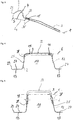
- FIG. 4 is a cross section through the B-pillar 1 along in the FIG. 1 shown section line IV-IV, which intersects the lower recess 15. It can be seen that the lower recess 15 is formed within the central web 11 of the sheet metal part 2, so that a central leg 39 of the B-pillar 1 in the section shown here from the fiber composite material of the fiber composite component 3 and the metal of the sheet metal part 2 is formed.
- FIGS. 5 to 7 Further cross sections through the B-pillar 1 are shown, wherein the associated section lines in the figure 1 are drawn. It can be seen that the recess, here the upper recess 14, can extend both over the central web 11 and over the side webs 12 of the sheet metal shaped part 2.
- the central leg 39 of the B-pillar 1 and also side walls 25 of the B-pillar 1 can be at least partially designed from the fiber composite material of the fiber composite component 3.
- the force introduction regions 18 are, as viewed in section through the B-pillar 1, completely embedded in the fiber composite component 3, so that the sheet metal part 2 is permanently connected to the fiber composite component 3.
- FIG. 9 a cross section through the B-pillar 1 in the region of the holding portion 16 is shown. It can be seen that the central web 11 of the sheet metal part 2 along the holding portion 16, viewed in section through the B-pillar 1, is completely embedded in the fiber composite component 3.
- the fiber composite component 3 completely covers the recesses 14, 15 or fills them. Accordingly, the central leg 39 of the at least partially hat profile-shaped B-pillar 1 is formed at least substantially from the fiber composite material of the fiber composite component 3.
- the fiber composite component 3 extends over both the upper recess 14 and the lower recess 15 and is continuous, that is not formed interrupted. Furthermore, the shape of the at least substantially U-shaped fiber composite component 3 at least partially follows the hat profile of the sheet metal part 2.
- the fiber composite component 3 is at least substantially U-shaped and limits the open cavity 10 on one side. In the FIG. 1 It can be seen that the fiber composite component 3 extends over at least 0.25 times the length L 1 of the B pillar 1, here in particular about 70% of the length L 1 .
- An upper end 20 of the fiber composite component 3 is spaced from an upper end 21 of the B-pillar 1, or the sheet metal part 2, with a distance of about 5% of the length L 1 .
- a lower end 22 of the fiber composite component 3 is spaced from a lower end 23 of the B-pillar 1, and the sheet metal part 2, with a distance of about 20 to 25% of the length L 1 .
- the fiber composite component 3 can optionally have at least one reinforcing insert, or respectively metallic insert 24.
- the reinforcing insert 24 is in the FIGS. 7 and 8 being shown in the FIG. 6 the B-pillar 1 is shown without such an insert.
- the reinforcing insert 24 can be incorporated into the laying structure of the surrounding fibers in a form-fitting manner, or supportingly, when the fiber composite component 3 is produced by braiding part of the fibers.
- the reinforcing insert 24 due to its surface texture, respectively roughness and / or a coordinated surface coating concept to be integrated into a matrix surrounding the fibers of the fiber composite material sustainable.
- the reinforcing insert 24 may be made of a cold or hot formed high, higher or highest strength steel, depending on the customer's requirement for crash performance.
- the reinforcing insert 24 may have a variable wall thickness. In the in FIG.
- the reinforcing insert 24 here may have an approximately U-shaped, respectively plate-shaped profile.
- the reinforcing insert 24 can also be designed to be narrower, in particular strip-shaped, or significantly wider, so that the reinforcing insert 24 can also extend significantly deeper into the side walls 25 of the B-pillar 1, as far as the side walls 25 through the fiber composite component 3 are formed.
- a blocking or decoupling layer 26 for example of an adhesive provided to prevent contact corrosion between the components, namely the sheet metal part 2 and the fiber composite component 3.
- the barrier or decoupling layer 26 may be provided between the fiber composite component 3 and the at least one reinforcing insert 24 or other metallic components incorporated in the fiber composite component 3.
- each side has a single-layer flange 27.
- the Fügeflansche 16 of the sheet metal part 2 are not covered by the fiber composite component 3, so that the B-pillar 1 in the inserted state only on the sheet metal part 2 to adjacent components, such as the vehicle outer skin 9 and / or a door seal and / or a glass surface, is connected.
- a side edge 28 of the fiber composite component 3 from a side edge 29 of the sheet metal part 2 such that the sheet metal part 2 between the side edge 28 of the fiber composite component 3 and the side edge 29 of the sheet metal part 2, the single-layer flange portion 27 for connecting adjacent components with the B-pillar. 1 having.
- the fiber composite material can be placed, for example, in a laying form, wherein the force introduction regions 18 of the sheet metal part 2 are embedded in the matrix of the fiber composite material.
- the sheet metal part 2 can be permanently connected to the fiber composite component 3, for example by lamination or fiber spraying, pressing or injection method.
- the fiber composite component 3 is permanently connected to the sheet metal part 2.
- the fiber composite component 3 is structurally integrated into the hybrid B-pillar 1, so that the main load of the B-pillar 1 in the region of the two recesses 14, 15 is taken over by the fiber composite component 3.
- FIGS. 10 and 11 a B-pillar 31 is shown according to a further embodiment of the present invention, which as far as possible the above-described embodiments according to the FIGS. 1 to 9 so that in terms of similarities to the above description reference is made.
- the same or modified details are provided with the same reference numerals as in the FIGS. 1 to 9 ,
- the essential difference consists in the integration of the upper metal section and the lower metal section into the fiber composite component 3.
- FIG. 10 is the B-pillar 31 in a functional state and in the FIG. 11 the B pillar 31 is shown in an unfinished state before the fiber composite material is applied to an upper sheet metal part 32 and a lower sheet metal part 33.
- the two sheet-metal shaped parts 32, 33 are axially spaced apart and connected to each other exclusively via the fiber composite component 3.
- the upper sheet metal shaped part 32 comprises the upper metal section 4 and the lower sheet metal shaped part 33 comprises the lower metal section 6 and a functional section 34 for connecting vehicle attachment parts to the B pillar 31.
- the B-pillar 31 has an upper recess 35 and a lower recess 36, which is covered by the fiber composite component 3, or filled.
- the upper recess 35 is formed, which can extend over about 0.2 to 0.6 times the length L 1 of the B-pillar 31, here over about 30% of the length L 1 .
- the upper recess 35 extends into both the upper sheet metal part 32 and the lower sheet metal part 33.
- the lower recess 36 is formed within the lower sheet metal molding 33 and may extend over about 0.1 to 0.3 times the length L 1 of the B pillar 1, here over about 10% of the length L 1 .
- Both sheet-metal shaped parts 32, 33 have, for the permanent connection with the fiber composite component 3, the force introduction regions 18 ', 18 ", which are completely embedded in the fiber composite component 3 as viewed in section through the B pillar 31.
- the force introduction regions 18', 18" of the upper and lower of the lower sheet metal part 32, 33 surround the upper recess 35 each U-shaped.
- the end edge 30 'associated with the upper sheet metal part 32 delimits the upper recess 35 axially upward and the lower end edge 30 "associated with the lower sheet metal part 33 axially delimits the lower recess 36.
- the distance L 30 between the upper end edge 30' and the lower end edge 30 can be at least 25% and at most 95% of the total length L 1 of the B-pillar 1 and is, here, about 60%.
- connecting means 38 for example screws or rivets, in addition to the attachment of the vehicle attachment parts in addition to the positive and non-positive connection between the lower sheet metal part 33 and the composite component 3 can be used.
Landscapes
- Engineering & Computer Science (AREA)
- Chemical & Material Sciences (AREA)
- Combustion & Propulsion (AREA)
- Transportation (AREA)
- Mechanical Engineering (AREA)
- Architecture (AREA)
- Structural Engineering (AREA)
- Body Structure For Vehicles (AREA)
Applications Claiming Priority (1)
| Application Number | Priority Date | Filing Date | Title |
|---|---|---|---|
| DE102018113141.0A DE102018113141A1 (de) | 2018-06-01 | 2018-06-01 | B-Säule für eine Kraftfahrzeugkarosserie sowie Kraftfahrzeugkarosserie mit einer solchen B-Säule |
Publications (2)
| Publication Number | Publication Date |
|---|---|
| EP3575189A1 true EP3575189A1 (fr) | 2019-12-04 |
| EP3575189B1 EP3575189B1 (fr) | 2022-04-13 |
Family
ID=66647249
Family Applications (1)
| Application Number | Title | Priority Date | Filing Date |
|---|---|---|---|
| EP19176432.3A Active EP3575189B1 (fr) | 2018-06-01 | 2019-05-24 | Pied milieu pour une carrosserie de véhicule ainsi que carrosserie de véhicule pourvue d'un tel pied milieu |
Country Status (4)
| Country | Link |
|---|---|
| US (1) | US11001307B2 (fr) |
| EP (1) | EP3575189B1 (fr) |
| CN (1) | CN110550110B (fr) |
| DE (1) | DE102018113141A1 (fr) |
Families Citing this family (3)
| Publication number | Priority date | Publication date | Assignee | Title |
|---|---|---|---|---|
| CN114555453B (zh) * | 2019-11-08 | 2024-06-14 | 自动工程有限公司 | 一种用于车辆框架的成形钣金部件和相应的生产方法 |
| DE102021122509A1 (de) | 2021-08-31 | 2023-03-02 | Dr. Ing. H.C. F. Porsche Aktiengesellschaft | Kraftfahrzeugstrukturbauteil mit einem metallischen Profil-Grundkörper und einem damit verbundenen faserverstärkten Verstärkungselement aus Kunststoff sowie Verfahren zur Herstellung eines solchen Kraftfahrzeugstrukturbauteils |
| DE102023119721B3 (de) | 2023-07-26 | 2024-06-27 | Dr. Ing. H.C. F. Porsche Aktiengesellschaft | Seitenaufprallverstärkung einer Fahrzeugkarosserie |
Citations (7)
| Publication number | Priority date | Publication date | Assignee | Title |
|---|---|---|---|---|
| DE102006027546A1 (de) | 2006-06-14 | 2007-12-20 | Volkswagen Ag | Aufprallschutzverstärkungsteil |
| DE102012023653A1 (de) | 2012-11-28 | 2014-05-28 | GM Global Technology Operations LLC (n. d. Gesetzen des Staates Delaware) | Kraftfahrzeugkarosserie mit Leichtbauteil |
| DE102013106070B3 (de) * | 2013-06-12 | 2014-07-17 | Leichtbau-Zentrum Sachsen Gmbh | Seitenwandgruppe für Personenkraftwagen |
| DE102015203644A1 (de) * | 2015-03-02 | 2016-09-08 | Bayerische Motoren Werke Aktiengesellschaft | Pressgehärtetes Blechformteil mit unterschiedlichen Blechdicken und Festigkeiten |
| DE102015115439B3 (de) * | 2015-09-14 | 2017-01-05 | Muhr Und Bender Kg | B-Säule für eine Kraftfahrzeugkarosserie und Verfahren zum Herstellen einer B-Säule |
| EP3138685A1 (fr) | 2015-09-03 | 2017-03-08 | Evonik Degussa GmbH | Composant hybride dote d'un renfort local constitue d'un materiau en fibres composites a base de polyurethane, reticule en deux etapes |
| DE102016116787B3 (de) * | 2016-09-07 | 2017-10-05 | Muhr Und Bender Kg | B-Säule für eine Kraftfahrzeugkarosserie sowie Kraftfahrzeugkarosserie mit einer solchen B-Säule |
Family Cites Families (14)
| Publication number | Priority date | Publication date | Assignee | Title |
|---|---|---|---|---|
| DE10232320A1 (de) * | 2002-07-17 | 2004-02-05 | Bayerische Motoren Werke Ag | Fahrzeugkarosserie mit einer B-Säule |
| US8905464B2 (en) * | 2009-10-29 | 2014-12-09 | Metalsa Automotive Gmbh | Vehicle part with structural reinforcement part |
| DE102011100050A1 (de) * | 2011-04-29 | 2012-10-31 | GM Global Technology Operations LLC (n. d. Gesetzen des Staates Delaware) | Stützelement für eineKraftfahrzeugkarosserie |
| DE102012207901B4 (de) * | 2012-05-11 | 2021-02-25 | Bayerische Motoren Werke Aktiengesellschaft | Fahrzeugkarosserie mit einem Dachquerspriegel |
| DE102012011878A1 (de) * | 2012-06-13 | 2013-12-19 | Audi Ag | Karosserie-Tragstruktur für eine Fahrzeug-Karosserie |
| DE102013200677A1 (de) * | 2013-01-17 | 2014-07-17 | Bayerische Motoren Werke Aktiengesellschaft | Karosseriestrukturelement und Verfahren zum Herstellen eines Karosseriestrukturelements |
| FR3008945B1 (fr) * | 2013-07-25 | 2018-03-02 | Compagnie Plastic Omnium | Montant lateral pour caisse de vehicule automobile perfectionne |
| DE102013226607A1 (de) * | 2013-12-19 | 2015-06-25 | Bayerische Motoren Werke Aktiengesellschaft | Karosseriestruktur in Knotenbauweise |
| FR3030356B1 (fr) * | 2014-12-23 | 2019-04-05 | Renault S.A.S | Procede de fabrication d'une piece de structure hybride de vehicule automobile et piece de structure hybride correspondante. |
| US9764769B2 (en) * | 2015-02-09 | 2017-09-19 | Honda Motor Co., Ltd. | Vehicle frame structural member assembly and method |
| CN204937248U (zh) * | 2015-08-18 | 2016-01-06 | 北京汽车股份有限公司 | 汽车b柱及汽车 |
| CN106853846B (zh) * | 2015-12-09 | 2022-02-01 | 福特全球技术公司 | 车身部件 |
| US10538686B2 (en) * | 2017-09-27 | 2020-01-21 | Honda Motor Co., Ltd. | Multi-material assembly and methods of making thereof |
| DE102018205826A1 (de) * | 2018-04-17 | 2019-10-17 | Röchling Automotive SE & Co. KG | Kfz-Karosserie mit Rohkarosse und Fahrzeugboden sowie einem Sicherungsstrukturbauteil |
-
2018
- 2018-06-01 DE DE102018113141.0A patent/DE102018113141A1/de not_active Withdrawn
-
2019
- 2019-05-24 EP EP19176432.3A patent/EP3575189B1/fr active Active
- 2019-05-28 US US16/423,394 patent/US11001307B2/en active Active
- 2019-06-03 CN CN201910474813.7A patent/CN110550110B/zh active Active
Patent Citations (7)
| Publication number | Priority date | Publication date | Assignee | Title |
|---|---|---|---|---|
| DE102006027546A1 (de) | 2006-06-14 | 2007-12-20 | Volkswagen Ag | Aufprallschutzverstärkungsteil |
| DE102012023653A1 (de) | 2012-11-28 | 2014-05-28 | GM Global Technology Operations LLC (n. d. Gesetzen des Staates Delaware) | Kraftfahrzeugkarosserie mit Leichtbauteil |
| DE102013106070B3 (de) * | 2013-06-12 | 2014-07-17 | Leichtbau-Zentrum Sachsen Gmbh | Seitenwandgruppe für Personenkraftwagen |
| DE102015203644A1 (de) * | 2015-03-02 | 2016-09-08 | Bayerische Motoren Werke Aktiengesellschaft | Pressgehärtetes Blechformteil mit unterschiedlichen Blechdicken und Festigkeiten |
| EP3138685A1 (fr) | 2015-09-03 | 2017-03-08 | Evonik Degussa GmbH | Composant hybride dote d'un renfort local constitue d'un materiau en fibres composites a base de polyurethane, reticule en deux etapes |
| DE102015115439B3 (de) * | 2015-09-14 | 2017-01-05 | Muhr Und Bender Kg | B-Säule für eine Kraftfahrzeugkarosserie und Verfahren zum Herstellen einer B-Säule |
| DE102016116787B3 (de) * | 2016-09-07 | 2017-10-05 | Muhr Und Bender Kg | B-Säule für eine Kraftfahrzeugkarosserie sowie Kraftfahrzeugkarosserie mit einer solchen B-Säule |
Also Published As
| Publication number | Publication date |
|---|---|
| EP3575189B1 (fr) | 2022-04-13 |
| DE102018113141A1 (de) | 2019-12-05 |
| US11001307B2 (en) | 2021-05-11 |
| US20190367095A1 (en) | 2019-12-05 |
| CN110550110A (zh) | 2019-12-10 |
| CN110550110B (zh) | 2023-03-31 |
Similar Documents
| Publication | Publication Date | Title |
|---|---|---|
| EP3293095B1 (fr) | Pied milieu de carrosserie de véhicule ainsi que carrosserie de véhicule pourvue d'un tel pied milieu | |
| EP2976250B1 (fr) | Seuil de porte pour une carrosserie de véhicule | |
| DE102015106812B4 (de) | Kraftfahrzeugsäule mit Verstärkungsblech sowie Verfahren zu dessen Herstellung | |
| DE10003878B4 (de) | Zusatzelement | |
| EP2895381B1 (fr) | Carrosserie de véhicule automobile comprenant une paroi latérale et son procédé de fabrication | |
| EP3150466A1 (fr) | Colonne b pour carrosserie de vehicule et son procede de production | |
| WO2007019979A1 (fr) | Tole de renforcement conçue pour une colonne b d'une carrosserie de vehicule | |
| DE102005043698A1 (de) | Seitenschweller einer Kraftwagenkarosserie | |
| WO2013075996A1 (fr) | Élément monobloc en tôle destiné à un véhicule | |
| EP1738943B1 (fr) | Structure de porte d'un véhicule automobile | |
| DE102008017055A1 (de) | Querträger für einen Stoßfänger eines Fahrzeugs und Verfahren zum Herstellen eines Querträgers | |
| DE102018207221A1 (de) | Energieabsorptionsbauteil für die Anordnung in einem hohlprofilartigen Schweller | |
| EP3575189B1 (fr) | Pied milieu pour une carrosserie de véhicule ainsi que carrosserie de véhicule pourvue d'un tel pied milieu | |
| EP2867096A1 (fr) | Élément de support et élément d'absorption d'énergie à construction hybride pour un véhicule automobile | |
| DE102013010332A1 (de) | Sandwichbauteil mit Verstärkungsprofil | |
| WO2018060143A1 (fr) | Élément structural pour une carrosserie de véhicule automobile | |
| DE102005036900A1 (de) | Kraftfahrzeug mit einer eine Bodenstruktur aufweisenden Karosserie, und wenigstens einem Versteifungselement zum Versteifen der Bodenstruktur | |
| EP1880924B1 (fr) | Poutre en tant que traverse ou longeron dans un véhicule automobile | |
| DE102008010720A1 (de) | Aufprallträger für ein Fahrzeug | |
| DE102015012262B4 (de) | Tür für einen Kraftwagen | |
| DE102005003978A1 (de) | Karosserie-Bauteil eines Kraftfahrzeuges | |
| EP3010740A1 (fr) | Élément de renforcement de portière de véhicule automobile, portière de véhicule automobile et procédé de fabrication d'un élément de renforcement | |
| DE102010054688A1 (de) | Bodenstruktur für ein Kraftfahrzeug, Fahrzeugkarosserie und Kraftfahrzeug | |
| DE102007050227B4 (de) | Fahrzeugtür | |
| DE102012206421B4 (de) | Kraftfahrzeug |
Legal Events
| Date | Code | Title | Description |
|---|---|---|---|
| PUAI | Public reference made under article 153(3) epc to a published international application that has entered the european phase |
Free format text: ORIGINAL CODE: 0009012 |
|
| STAA | Information on the status of an ep patent application or granted ep patent |
Free format text: STATUS: THE APPLICATION HAS BEEN PUBLISHED |
|
| AK | Designated contracting states |
Kind code of ref document: A1 Designated state(s): AL AT BE BG CH CY CZ DE DK EE ES FI FR GB GR HR HU IE IS IT LI LT LU LV MC MK MT NL NO PL PT RO RS SE SI SK SM TR |
|
| AX | Request for extension of the european patent |
Extension state: BA ME |
|
| STAA | Information on the status of an ep patent application or granted ep patent |
Free format text: STATUS: REQUEST FOR EXAMINATION WAS MADE |
|
| 17P | Request for examination filed |
Effective date: 20200504 |
|
| RBV | Designated contracting states (corrected) |
Designated state(s): AL AT BE BG CH CY CZ DE DK EE ES FI FR GB GR HR HU IE IS IT LI LT LU LV MC MK MT NL NO PL PT RO RS SE SI SK SM TR |
|
| GRAP | Despatch of communication of intention to grant a patent |
Free format text: ORIGINAL CODE: EPIDOSNIGR1 |
|
| STAA | Information on the status of an ep patent application or granted ep patent |
Free format text: STATUS: GRANT OF PATENT IS INTENDED |
|
| INTG | Intention to grant announced |
Effective date: 20211111 |
|
| RIC1 | Information provided on ipc code assigned before grant |
Ipc: B62D 29/00 20060101ALI20211029BHEP Ipc: B62D 25/04 20060101AFI20211029BHEP |
|
| GRAS | Grant fee paid |
Free format text: ORIGINAL CODE: EPIDOSNIGR3 |
|
| GRAA | (expected) grant |
Free format text: ORIGINAL CODE: 0009210 |
|
| STAA | Information on the status of an ep patent application or granted ep patent |
Free format text: STATUS: THE PATENT HAS BEEN GRANTED |
|
| AK | Designated contracting states |
Kind code of ref document: B1 Designated state(s): AL AT BE BG CH CY CZ DE DK EE ES FI FR GB GR HR HU IE IS IT LI LT LU LV MC MK MT NL NO PL PT RO RS SE SI SK SM TR |
|
| REG | Reference to a national code |
Ref country code: GB Ref legal event code: FG4D Free format text: NOT ENGLISH |
|
| REG | Reference to a national code |
Ref country code: CH Ref legal event code: EP |
|
| REG | Reference to a national code |
Ref country code: DE Ref legal event code: R096 Ref document number: 502019004025 Country of ref document: DE |
|
| REG | Reference to a national code |
Ref country code: IE Ref legal event code: FG4D Free format text: LANGUAGE OF EP DOCUMENT: GERMAN |
|
| REG | Reference to a national code |
Ref country code: AT Ref legal event code: REF Ref document number: 1483207 Country of ref document: AT Kind code of ref document: T Effective date: 20220515 |
|
| REG | Reference to a national code |
Ref country code: LT Ref legal event code: MG9D |
|
| REG | Reference to a national code |
Ref country code: NL Ref legal event code: MP Effective date: 20220413 |
|
| PG25 | Lapsed in a contracting state [announced via postgrant information from national office to epo] |
Ref country code: NL Free format text: LAPSE BECAUSE OF FAILURE TO SUBMIT A TRANSLATION OF THE DESCRIPTION OR TO PAY THE FEE WITHIN THE PRESCRIBED TIME-LIMIT Effective date: 20220413 |
|
| PG25 | Lapsed in a contracting state [announced via postgrant information from national office to epo] |
Ref country code: SE Free format text: LAPSE BECAUSE OF FAILURE TO SUBMIT A TRANSLATION OF THE DESCRIPTION OR TO PAY THE FEE WITHIN THE PRESCRIBED TIME-LIMIT Effective date: 20220413 Ref country code: PT Free format text: LAPSE BECAUSE OF FAILURE TO SUBMIT A TRANSLATION OF THE DESCRIPTION OR TO PAY THE FEE WITHIN THE PRESCRIBED TIME-LIMIT Effective date: 20220816 Ref country code: NO Free format text: LAPSE BECAUSE OF FAILURE TO SUBMIT A TRANSLATION OF THE DESCRIPTION OR TO PAY THE FEE WITHIN THE PRESCRIBED TIME-LIMIT Effective date: 20220713 Ref country code: LT Free format text: LAPSE BECAUSE OF FAILURE TO SUBMIT A TRANSLATION OF THE DESCRIPTION OR TO PAY THE FEE WITHIN THE PRESCRIBED TIME-LIMIT Effective date: 20220413 Ref country code: HR Free format text: LAPSE BECAUSE OF FAILURE TO SUBMIT A TRANSLATION OF THE DESCRIPTION OR TO PAY THE FEE WITHIN THE PRESCRIBED TIME-LIMIT Effective date: 20220413 Ref country code: GR Free format text: LAPSE BECAUSE OF FAILURE TO SUBMIT A TRANSLATION OF THE DESCRIPTION OR TO PAY THE FEE WITHIN THE PRESCRIBED TIME-LIMIT Effective date: 20220714 Ref country code: FI Free format text: LAPSE BECAUSE OF FAILURE TO SUBMIT A TRANSLATION OF THE DESCRIPTION OR TO PAY THE FEE WITHIN THE PRESCRIBED TIME-LIMIT Effective date: 20220413 Ref country code: ES Free format text: LAPSE BECAUSE OF FAILURE TO SUBMIT A TRANSLATION OF THE DESCRIPTION OR TO PAY THE FEE WITHIN THE PRESCRIBED TIME-LIMIT Effective date: 20220413 Ref country code: BG Free format text: LAPSE BECAUSE OF FAILURE TO SUBMIT A TRANSLATION OF THE DESCRIPTION OR TO PAY THE FEE WITHIN THE PRESCRIBED TIME-LIMIT Effective date: 20220713 |
|
| PG25 | Lapsed in a contracting state [announced via postgrant information from national office to epo] |
Ref country code: RS Free format text: LAPSE BECAUSE OF FAILURE TO SUBMIT A TRANSLATION OF THE DESCRIPTION OR TO PAY THE FEE WITHIN THE PRESCRIBED TIME-LIMIT Effective date: 20220413 Ref country code: PL Free format text: LAPSE BECAUSE OF FAILURE TO SUBMIT A TRANSLATION OF THE DESCRIPTION OR TO PAY THE FEE WITHIN THE PRESCRIBED TIME-LIMIT Effective date: 20220413 Ref country code: LV Free format text: LAPSE BECAUSE OF FAILURE TO SUBMIT A TRANSLATION OF THE DESCRIPTION OR TO PAY THE FEE WITHIN THE PRESCRIBED TIME-LIMIT Effective date: 20220413 Ref country code: IS Free format text: LAPSE BECAUSE OF FAILURE TO SUBMIT A TRANSLATION OF THE DESCRIPTION OR TO PAY THE FEE WITHIN THE PRESCRIBED TIME-LIMIT Effective date: 20220813 |
|
| REG | Reference to a national code |
Ref country code: CH Ref legal event code: PL |
|
| REG | Reference to a national code |
Ref country code: DE Ref legal event code: R097 Ref document number: 502019004025 Country of ref document: DE |
|
| REG | Reference to a national code |
Ref country code: BE Ref legal event code: MM Effective date: 20220531 |
|
| PG25 | Lapsed in a contracting state [announced via postgrant information from national office to epo] |
Ref country code: SM Free format text: LAPSE BECAUSE OF FAILURE TO SUBMIT A TRANSLATION OF THE DESCRIPTION OR TO PAY THE FEE WITHIN THE PRESCRIBED TIME-LIMIT Effective date: 20220413 Ref country code: SK Free format text: LAPSE BECAUSE OF FAILURE TO SUBMIT A TRANSLATION OF THE DESCRIPTION OR TO PAY THE FEE WITHIN THE PRESCRIBED TIME-LIMIT Effective date: 20220413 Ref country code: RO Free format text: LAPSE BECAUSE OF FAILURE TO SUBMIT A TRANSLATION OF THE DESCRIPTION OR TO PAY THE FEE WITHIN THE PRESCRIBED TIME-LIMIT Effective date: 20220413 Ref country code: MC Free format text: LAPSE BECAUSE OF FAILURE TO SUBMIT A TRANSLATION OF THE DESCRIPTION OR TO PAY THE FEE WITHIN THE PRESCRIBED TIME-LIMIT Effective date: 20220413 Ref country code: LU Free format text: LAPSE BECAUSE OF NON-PAYMENT OF DUE FEES Effective date: 20220524 Ref country code: LI Free format text: LAPSE BECAUSE OF NON-PAYMENT OF DUE FEES Effective date: 20220531 Ref country code: EE Free format text: LAPSE BECAUSE OF FAILURE TO SUBMIT A TRANSLATION OF THE DESCRIPTION OR TO PAY THE FEE WITHIN THE PRESCRIBED TIME-LIMIT Effective date: 20220413 Ref country code: DK Free format text: LAPSE BECAUSE OF FAILURE TO SUBMIT A TRANSLATION OF THE DESCRIPTION OR TO PAY THE FEE WITHIN THE PRESCRIBED TIME-LIMIT Effective date: 20220413 Ref country code: CZ Free format text: LAPSE BECAUSE OF FAILURE TO SUBMIT A TRANSLATION OF THE DESCRIPTION OR TO PAY THE FEE WITHIN THE PRESCRIBED TIME-LIMIT Effective date: 20220413 Ref country code: CH Free format text: LAPSE BECAUSE OF NON-PAYMENT OF DUE FEES Effective date: 20220531 |
|
| PLBE | No opposition filed within time limit |
Free format text: ORIGINAL CODE: 0009261 |
|
| STAA | Information on the status of an ep patent application or granted ep patent |
Free format text: STATUS: NO OPPOSITION FILED WITHIN TIME LIMIT |
|
| 26N | No opposition filed |
Effective date: 20230116 |
|
| PG25 | Lapsed in a contracting state [announced via postgrant information from national office to epo] |
Ref country code: AL Free format text: LAPSE BECAUSE OF FAILURE TO SUBMIT A TRANSLATION OF THE DESCRIPTION OR TO PAY THE FEE WITHIN THE PRESCRIBED TIME-LIMIT Effective date: 20220413 |
|
| PG25 | Lapsed in a contracting state [announced via postgrant information from national office to epo] |
Ref country code: IE Free format text: LAPSE BECAUSE OF NON-PAYMENT OF DUE FEES Effective date: 20220524 |
|
| PG25 | Lapsed in a contracting state [announced via postgrant information from national office to epo] |
Ref country code: SI Free format text: LAPSE BECAUSE OF FAILURE TO SUBMIT A TRANSLATION OF THE DESCRIPTION OR TO PAY THE FEE WITHIN THE PRESCRIBED TIME-LIMIT Effective date: 20220413 Ref country code: BE Free format text: LAPSE BECAUSE OF NON-PAYMENT OF DUE FEES Effective date: 20220531 |
|
| PG25 | Lapsed in a contracting state [announced via postgrant information from national office to epo] |
Ref country code: IT Free format text: LAPSE BECAUSE OF FAILURE TO SUBMIT A TRANSLATION OF THE DESCRIPTION OR TO PAY THE FEE WITHIN THE PRESCRIBED TIME-LIMIT Effective date: 20220413 |
|
| PG25 | Lapsed in a contracting state [announced via postgrant information from national office to epo] |
Ref country code: HU Free format text: LAPSE BECAUSE OF FAILURE TO SUBMIT A TRANSLATION OF THE DESCRIPTION OR TO PAY THE FEE WITHIN THE PRESCRIBED TIME-LIMIT; INVALID AB INITIO Effective date: 20190524 |
|
| PG25 | Lapsed in a contracting state [announced via postgrant information from national office to epo] |
Ref country code: MK Free format text: LAPSE BECAUSE OF FAILURE TO SUBMIT A TRANSLATION OF THE DESCRIPTION OR TO PAY THE FEE WITHIN THE PRESCRIBED TIME-LIMIT Effective date: 20220413 Ref country code: CY Free format text: LAPSE BECAUSE OF FAILURE TO SUBMIT A TRANSLATION OF THE DESCRIPTION OR TO PAY THE FEE WITHIN THE PRESCRIBED TIME-LIMIT Effective date: 20220413 |
|
| PG25 | Lapsed in a contracting state [announced via postgrant information from national office to epo] |
Ref country code: TR Free format text: LAPSE BECAUSE OF FAILURE TO SUBMIT A TRANSLATION OF THE DESCRIPTION OR TO PAY THE FEE WITHIN THE PRESCRIBED TIME-LIMIT Effective date: 20220413 |
|
| PG25 | Lapsed in a contracting state [announced via postgrant information from national office to epo] |
Ref country code: MT Free format text: LAPSE BECAUSE OF FAILURE TO SUBMIT A TRANSLATION OF THE DESCRIPTION OR TO PAY THE FEE WITHIN THE PRESCRIBED TIME-LIMIT Effective date: 20220413 |
|
| PG25 | Lapsed in a contracting state [announced via postgrant information from national office to epo] |
Ref country code: BG Free format text: LAPSE BECAUSE OF FAILURE TO SUBMIT A TRANSLATION OF THE DESCRIPTION OR TO PAY THE FEE WITHIN THE PRESCRIBED TIME-LIMIT Effective date: 20220413 |
|
| PG25 | Lapsed in a contracting state [announced via postgrant information from national office to epo] |
Ref country code: BG Free format text: LAPSE BECAUSE OF FAILURE TO SUBMIT A TRANSLATION OF THE DESCRIPTION OR TO PAY THE FEE WITHIN THE PRESCRIBED TIME-LIMIT Effective date: 20220413 |
|
| PGFP | Annual fee paid to national office [announced via postgrant information from national office to epo] |
Ref country code: DE Payment date: 20250509 Year of fee payment: 7 |
|
| PGFP | Annual fee paid to national office [announced via postgrant information from national office to epo] |
Ref country code: GB Payment date: 20250429 Year of fee payment: 7 |
|
| REG | Reference to a national code |
Ref country code: AT Ref legal event code: MM01 Ref document number: 1483207 Country of ref document: AT Kind code of ref document: T Effective date: 20240524 |
|
| PGFP | Annual fee paid to national office [announced via postgrant information from national office to epo] |
Ref country code: FR Payment date: 20250429 Year of fee payment: 7 |
|
| PG25 | Lapsed in a contracting state [announced via postgrant information from national office to epo] |
Ref country code: AT Free format text: LAPSE BECAUSE OF NON-PAYMENT OF DUE FEES Effective date: 20240524 |
|
| PGFP | Annual fee paid to national office [announced via postgrant information from national office to epo] |
Ref country code: AT Payment date: 20260410 Year of fee payment: 5 |