EP3575457B1 - Verfahren zum ermitteln von betriebszuständen einer textilmaschine sowie eine textilmaschine - Google Patents
Verfahren zum ermitteln von betriebszuständen einer textilmaschine sowie eine textilmaschine Download PDFInfo
- Publication number
- EP3575457B1 EP3575457B1 EP19175519.8A EP19175519A EP3575457B1 EP 3575457 B1 EP3575457 B1 EP 3575457B1 EP 19175519 A EP19175519 A EP 19175519A EP 3575457 B1 EP3575457 B1 EP 3575457B1
- Authority
- EP
- European Patent Office
- Prior art keywords
- drive
- load variable
- load
- workstation
- profile
- Prior art date
- Legal status (The legal status is an assumption and is not a legal conclusion. Google has not performed a legal analysis and makes no representation as to the accuracy of the status listed.)
- Active
Links
Images
Classifications
-
- B—PERFORMING OPERATIONS; TRANSPORTING
- B65—CONVEYING; PACKING; STORING; HANDLING THIN OR FILAMENTARY MATERIAL
- B65H—HANDLING THIN OR FILAMENTARY MATERIAL, e.g. SHEETS, WEBS, CABLES
- B65H63/00—Warning or safety devices, e.g. automatic fault detectors, stop-motions ; Quality control of the package
-
- B—PERFORMING OPERATIONS; TRANSPORTING
- B65—CONVEYING; PACKING; STORING; HANDLING THIN OR FILAMENTARY MATERIAL
- B65H—HANDLING THIN OR FILAMENTARY MATERIAL, e.g. SHEETS, WEBS, CABLES
- B65H54/00—Winding, coiling, or depositing filamentary material
- B65H54/70—Other constructional features of yarn-winding machines
- B65H54/74—Driving arrangements
-
- D—TEXTILES; PAPER
- D01—NATURAL OR MAN-MADE THREADS OR FIBRES; SPINNING
- D01G—PRELIMINARY TREATMENT OF FIBRES, e.g. FOR SPINNING
- D01G31/00—Warning or safety devices, e.g. automatic fault detectors, stop motions
- D01G31/006—On-line measurement and recording of process and product parameters
-
- D—TEXTILES; PAPER
- D01—NATURAL OR MAN-MADE THREADS OR FIBRES; SPINNING
- D01H—SPINNING OR TWISTING
- D01H1/00—Spinning or twisting machines in which the product is wound-up continuously
- D01H1/14—Details
- D01H1/20—Driving or stopping arrangements
-
- D—TEXTILES; PAPER
- D01—NATURAL OR MAN-MADE THREADS OR FIBRES; SPINNING
- D01H—SPINNING OR TWISTING
- D01H13/00—Other common constructional features, details or accessories
- D01H13/32—Counting, measuring, recording or registering devices
-
- D—TEXTILES; PAPER
- D01—NATURAL OR MAN-MADE THREADS OR FIBRES; SPINNING
- D01H—SPINNING OR TWISTING
- D01H4/00—Open-end spinning machines or arrangements for imparting twist to independently moving fibres separated from slivers; Piecing arrangements therefor; Covering endless core threads with fibres by open-end spinning techniques
- D01H4/42—Control of driving or stopping
-
- D—TEXTILES; PAPER
- D01—NATURAL OR MAN-MADE THREADS OR FIBRES; SPINNING
- D01H—SPINNING OR TWISTING
- D01H4/00—Open-end spinning machines or arrangements for imparting twist to independently moving fibres separated from slivers; Piecing arrangements therefor; Covering endless core threads with fibres by open-end spinning techniques
- D01H4/48—Piecing arrangements; Control therefor
-
- B—PERFORMING OPERATIONS; TRANSPORTING
- B65—CONVEYING; PACKING; STORING; HANDLING THIN OR FILAMENTARY MATERIAL
- B65H—HANDLING THIN OR FILAMENTARY MATERIAL, e.g. SHEETS, WEBS, CABLES
- B65H2701/00—Handled material; Storage means
- B65H2701/30—Handled filamentary material
- B65H2701/31—Textiles threads or artificial strands of filaments
-
- G—PHYSICS
- G05—CONTROLLING; REGULATING
- G05B—CONTROL OR REGULATING SYSTEMS IN GENERAL; FUNCTIONAL ELEMENTS OF SUCH SYSTEMS; MONITORING OR TESTING ARRANGEMENTS FOR SUCH SYSTEMS OR ELEMENTS
- G05B2219/00—Program-control systems
- G05B2219/30—Nc systems
- G05B2219/45—Nc applications
- G05B2219/45191—Spinning, web spinning
Definitions
- the present invention relates to a method for determining a functional status at a work station of a textile machine, in particular an open-end or air-jet spinning machine, the textile machine comprising a large number of work stations, and each work station comprising at least one drive, with the aid of which a treatment agent assigned to the drive of the respective workplace for treating a fiber material. Furthermore, the invention relates to a textile machine for carrying out a method for determining the functional status at a work station.
- a spinning machine with at least one sensor which senses an operating state of the spinning machine and emits a signal characterizing this operating state. Furthermore, at least one actuator is provided, to which this signal is sent and which initiates a measure based on this signal.
- measuring the operating state using the sensor is disadvantageous, since this represents an additional, cost-incurring component.
- From the DE 29 50 063 A1 discloses a monitoring circuit for detecting malfunctions in a textile machine, which has at least one group of working elements that has a large number of working elements, the working elements of which are each assigned to a work station and are identical to each other and can be driven by an individual drive each with an electric motor.
- the malfunctions are detected in that a phase angle of a motor current is compared with a reference signal.
- the reference signal applies equally to the large number of individual drives.
- a method for monitoring spinning positions of a spinning machine in particular a ring spinning machine, is known.
- Spindles are arranged at the spinning positions, onto which the yarn produced is wound.
- the method is characterized in that during the start-up phase, the operating phase and the run-down phase of at least one motor driving the spindles, the speed of the spindle or the power consumption of the spindle motor is determined directly at least at part of the spinning position as a representative actual value. This actual value is compared in each case with a predefinable desired value that is variable over time according to a predefined speed program.
- the fault is classified as yarn breakage or high speed or as slow speed in the other case, and a corresponding alarm signal is emitted triggered.
- From the DE 44 04 243 A1 discloses a method and a device for operating an open-end rotor spinning unit with a single-motor electric drive of the spinning rotor.
- the electrical energy supplied to the drive is monitored.
- the course of the actual value of a variable representing the supply of energy is compared with the course of the setpoint value assigned to the respective operating phase.
- the drive is switched off when the deviation of the actual values of this variable, which represents the energy supply, from the desired values exceeds limit values.
- a limit value can be a maximum value which, if exceeded for a short time, leads to shutdown. However, it can also be a lower value which, if exceeded, also leads to shutdown for a definable period of time.
- the monitoring is advantageously implemented by forming an integral with an increasing integration range from the starting point.
- an alarm signal can be given depending on various conditions to be generated.
- the current consumption is to be used as the variable representing the energy supply, which very clearly characterizes the disturbance-related load increase in the rotor drive, which deviates from setpoint values.
- a method and device for controlling a textile machine or a driven part of a textile machine is known.
- a movable part of the textile machine being driven by an electric motor directly or via a mechanical interface, which is controlled by means of an actuating unit, and that at least one operating parameter of the electric motor and/or the actuating unit is measured and evaluated in such a way that at least one system-related or engine wear-related state variable is determined.
- the object of the present invention is therefore to remedy the disadvantage of the prior art.
- the object is achieved by a method for determining a functional status at a work station of a textile machine and a textile machine with the features of the independent patent claims.
- a method for determining a functional status at a work station of a textile machine is proposed.
- the textile machine can be, for example, an open-end spinning machine or an air-jet spinning machine.
- the functional status at the work site can be, for example, wear and tear, a malfunction, a blockage, a probability of failure, a productivity and/or a service life.
- the jamming can occur between moving components of the work site.
- the functional status can also be an operating state of a treatment agent.
- the textile machine also includes a plurality of work stations, so that the productivity of the textile machine is multiplied according to the number of work stations.
- Each work station also has at least one drive, with the aid of which at least one treatment means assigned to the drive of the respective work station is operated for treating a fiber material.
- the treatment agents treat the fibrous material in a way that allows the worksite to produce its end or intermediate product.
- the treatment means can be structural units, tools and/or devices that process or forward the fiber material.
- the work station can be a card that can process undirected individual fibers into a non-woven fabric.
- the treatment means can be, for example, a roller which is set in rotation by the drive in order to align the unaligned fibers.
- the fiber material can also be a sliver which is first dissolved into individual fibers in a spinning station by a treatment means, for example a dissolving unit, which are then spun into a yarn by a treatment means in the form of a spinning rotor.
- the drive can drive the opening unit or the spinning rotor.
- the work station can also be a rewinding unit, by means of which a yarn is rewound from one bobbin to another bobbin.
- At least the functional status of at least one treatment agent is determined based on a measurement of a load variable of the at least one drive. Additionally or alternatively, a functional status of a drive can be determined. In addition or as an alternative, a functional status of the work station can be inferred from the functional status of the treatment agent and/or the drive. With a functional status that indicates, for example, that a spinning rotor is not 100% functional, the functional status of the job is also restricted. If the functional status is an operating state of a treatment agent, it can be determined by measuring the load size whether the treatment agent, in particular the opening unit, or the work station is in regular operation or in preparation operation.
- the functional status of the drive can be determined on which the load size is measured.
- the load variable is a load angle of the at least one drive.
- the load angle is defined as an angle between a stator field and a rotor field of the drive.
- the load angle is the angle between the stator field and the rotor field of the electric drive. With an unloaded drive, the load angle is 0°, whereas the load angle increases with an increasing load. At a load angle of 0°, the stator field and the rotor field are oriented anti-parallel to one another. If, on the other hand, the drive is loaded, the load angle increases, so that the functional status can be deduced from this. With the help of the load angle, conclusions can be drawn about the load acting on the drive. In addition, changes in the load on the drive can be inferred from a change in the load angle. For example, if the drive at the work site jams, the load angle increases. The deadlock can be inferred from this information, so that the functional status is determined.
- the load size is measured at least on the drive which is assigned to a treatment means in the form of an opening unit, a spinning rotor, a traversing device, a pair of draw-off rollers, a bobbin and/or a winding roller.
- a treatment means in the form of an opening unit, a spinning rotor, a traversing device, a pair of draw-off rollers, a bobbin and/or a winding roller.
- a probability of failure, a service life and/or a maintenance interval of a treatment agent and/or a drive can be determined based on the measurement of the load size. For example, by recognizing the wear and tear, an exchange of the treatment agent can be planned. Based on the probability of failure or the service life, it is possible to plan how much of the treatment agent should be kept ready for future replacement.
- a maintenance plan for the workplace and/or the textile machine can be planned on the basis of the maintenance intervals.
- a productivity of the work station can be determined based on the measurement of the load size. This allows production costs for an end product to be calculated. As a result, for example, jobs with low productivity can be treated in a special way, for example by being switched off or maintained more intensively. If the job has a high level of productivity, at least one drive is more heavily loaded, so that the load size changes. In particular, if the workplace has a high level of productivity, all the drives at the workplace are subjected to an equal higher load, so that the increased productivity can be inferred from this.
- the presence of the fiber material in the work area can be determined by measuring the load size. If one drive of the treatment means or several, in particular all, drives of the treatment means of the work site is/are unloaded, the load size or the load sizes of the drives, for example in the form of the load angle, is essentially zero or when the drives are idling, at least significantly lower than in the case of loaded ones Drives, which can be an indication of the non-presence or absence of the fiber material. For example, it can happen at yarn-producing workplaces that a sliver stored in a can for producing a yarn has run out, so that the production of yarn is interrupted as a result, but the drives of the workplace continue to operate the treatment means.
- the work station can be switched off and/or a corresponding message can be sent in order to save energy or to draw the attention of operating personnel to refilling the fiber material.
- excessive wear of the idle treatment means, in particular the feed roller can be avoided.
- piecing it can be recognized whether fiber material is present or not Fiber material, the drive of both the opening unit and the feed unit of the spinning position are stopped. In this way, a useless piecing process can be avoided.
- the blocking of a treatment agent is determined before an end position, a stop position and/or a stop position of the treatment agent is reached. Since the blocking of the treatment agent is a similar state to reaching the end position, the stop position and/or the stop position, it can be advantageous to recognize the blocking before the corresponding position is reached, in order not to start with the end position, the stop position being reached and/or confused with the stop position.
- the treatment means can be a traversing device that oscillates back and forth between two end positions. In the end positions, the traversing direction of the traversing device is reversed, so that a specific course or change in the load size occurs in the end positions, which is at least similar in both end positions. From a comparison of the behavior of the load size during blocking and the behavior of the load size in the end positions, conclusions can be drawn about the blocking between the end positions.
- the load size is detected as exceeding a limit value.
- a limit value of 90° can be selected for the load angle, since the drive tilts and can come to a standstill from this load angle.
- falling below a limit value of the load size can also be detected. It can thus be concluded that the load on the drive has fallen below.
- a load size profile is created from the measurement of the load size.
- the load size be plotted against time, for example, in a time interval.
- changes in the functional status of a treatment agent that occur relatively abruptly can be detected by means of a load size profile that describes the load size profile in a comparatively short time interval, for example a few seconds. This means, for example, that blockages can be detected that essentially occur within a few seconds.
- the load size profile changes relatively quickly, so that the creation of the load size profile in the small time interval is sufficient. If the load size profile is only created within a few seconds, errors such as blockages or the absence of the fiber material can be detected.
- the load size profile can also be created over a longer period of time or in a longer time interval.
- the length of the period depends on the type of functional status that is to be determined. For example, if wear of a treatment agent is to be detected, the load magnitude profile can be created over a period of time where the wear has a noticeable effect on the load magnitude. Such a period can easily amount to a few days to weeks. Over this long period of time, the load size can change due to wear, which can be recognized from the load size profile, which was recorded over several days to weeks.
- the load size profile can be created continuously so that the functional status of the treatment agent and/or the drive is continuously monitored.
- the load size profile can also be created at specific time intervals, so that the measuring and/or computing effort for the comparison is comparatively low.
- At least one reference value, preferably a reference profile, of the load size of the drive is created from the measurement of the load size.
- a reference profile of the spinning rotor drive to be created can be created.
- the reference profile can be recorded over a certain period of time.
- the reference profile is preferably created when the functional status is normal, ie when there is no malfunction or the like.
- the reference profile indicates the course of the load angle over time. With the help of the reference value or reference profile, a comparison to normal operation of the workplace is possible.
- a reference value for the load size of the drive of the opening unit can be created.
- the reference value can also be created when the functional status is normal, ie there is fibrous material at the work site.
- the reference value or the reference profile is created during a first starting phase of the job. Additionally or alternatively, the reference value or the reference profile can also be created during a first start-up phase of the drive and/or the treatment means.
- the first starting phase is after the work site has been completed, while all components of the work site are still functioning as intended, i.e. the treatment agents are generally not showing any signs of wear or the like and are not blocked, for example.
- the workplace therefore shows no wear and tear, no malfunctions, the longest service life and the lowest probability of failure.
- a reference profile created in the meantime thus reflects the preferred functional status of the job.
- Creating a reference value during the first starting phase of a treatment agent can be useful, for example, in order to determine the presence of the fiber material or possibly also a thread in the treatment agent.
- a reference value for the drive of the opening unit can be created immediately after the start of the piecing process, when fiber feeding has not yet started and the opening unit is therefore still idling without combing out fiber material. If necessary, the reference value can even be created during the starter.
- the reference value or the reference profile can advantageously be compared with the currently measured load size or the recorded load size profile.
- the currently measured load size or the load size profile reflects the current functional status of the drive and/or the treatment agent.
- differences between the current functional status and the functional status during a point in time at which the drive, the treatment device or devices and/or the work station were functioning as intended can be determined. If, for example, in the above example of the opening unit after the start of the fiber feed or during ongoing spinning operation, the currently measured value of the load size is above the previously determined reference value, it is assumed that the sliver is present and the piecing or the regular spinning process is continued.
- a course of the load size profile of the drive is compared with a current position of the treatment means at the work site driven by the drive.
- the course of the load size profile of the drive can also be compared with a current rotational position of the treatment means at the work site driven by the drive.
- the driven treatment means of the work station can be, for example, the traversing device, so that an offset between a target position and an actual position of the traversing device can be detected by comparing the course of the load size profile with the current position.
- the progression of the load magnitude profile has a specific progression, for example when the traversing device is driven by the drive, particularly at reversal points of the traversing device. Based on a comparison of a current position of Oscillating device can be closed on a difference between the target and actual position.
- the load size of a drive at a first job is compared with the load size of the corresponding drive at a second job.
- the load size profile of the drive of the first work station can also be compared with the load size profile of the corresponding drive of the second work station.
- the load sizes and/or the load size profiles of the drives of the spinning rotors of the two work stations can be compared with one another. This allows the functional status of the two jobs to be compared. For example, it can thus be recognized which of the two spinning rotors of the two work stations has a higher productivity.
- the drive of one spinning rotor is more heavily loaded than the drive of the other spinning rotor.
- the load sizes of the two drives assigned to the spinning rotors are different, so that conclusions can be drawn about the productivity of the work stations or the difference in the productivities of the two work stations.
- the wear of the two spinning rotors can be detected, since the two load sizes and/or the load size profiles differ from one another in this case.
- the deviation of the two load sizes and/or the load size profiles of the two drives can be compared with one another.
- the drives from more than two jobs can also be compared.
- the drives which are assigned to a specific treatment agent can be compared with one another.
- the load sizes and/or the load size profiles of some of the drives of the spinning rotors of the textile machine or even the load sizes and/or the load size profiles of all drives of the spinning rotors of a textile machine can be compared with one another. This makes it possible, for example, to determine which spinning rotor has the highest productivity or, for example, has the least amount of wear. For example, if all drives of the first job are more heavily loaded than all drives of the second job, this can be an indication that the first job has a higher productivity than the second job.
- the load size of at least a first drive of a job is compared with a load size of a second drive of the same job.
- the load size profile of at least the first drive of the work station can be compared with the load size profile of the second drive of the same work station.
- the two drives or the treatment means operated with the drives can, for example, be arranged one behind the other in a delivery direction of a yarn, in particular directly. In this way, for example, a malfunction that occurs between these two drives can be determined.
- the load sizes and/or load size profiles of a number of drives at a work site can also be compared with one another.
- the load size profile can also be evaluated statistically.
- wear can be inferred from a continuous, in particular steady, change in the load size and/or the load size profile, so that the change in the load size can be measured.
- a slope (positive or negative) can thus be determined over time, for example.
- a standard deviation, a variance and/or a statistical distribution, in particular a Gaussian distribution, of the load variable can be evaluated.
- a mean value of the load size is determined. Additionally or alternatively, a fluctuation in the load size can also be determined. Likewise additionally or alternatively, the mean value and/or the Fluctuation of the load size profile can be determined. A mean value over time can be formed as the mean value, for example. It is also advantageous if the periodicity of the fluctuation is determined. The periodic fluctuation of the load size can occur, for example, in a drive that drives a treatment device with an imbalance.
- the load size is measured with the aid of a control of the work station and/or the textile machine.
- the functional status of the drive and/or the treatment agent can also be determined with the aid of the controller.
- the controller can preferably be connected to the at least one drive, so that the controller can control the drive and receive the load size from the drive or measure it itself.
- an evaluation program that creates the load size, changes in the load size, the reference profile and/or the load size profile can be stored in the controller. This data can also be stored in a memory in the controller or can already be present.
- the controller can measure the load size, for example, by measuring a current and/or a voltage of the drive.
- the controller can determine the load size by measuring an induced voltage that occurs during operation of the drive.
- the controller can also measure a phase shift between the current, the voltage of the drive and the induced voltage and use this to determine the load size.
- a textile machine in particular an open-end or air-jet spinning machine, with a large number of work stations, each of which has at least one drive.
- at least one treatment means assigned to the drive of the respective work station can be operated for treating a fiber material.
- the treatment means can be, for example, an opening unit, a spinning rotor, a pair of take-off rollers, a traversing device and/or a winding roller.
- the textile machine has at least one controller with which at least one drive of the textile machine can be controlled.
- a work station and/or a group of work stations can also have the controller.
- the controller includes means with which the controller can control the drives.
- the controller can also have a memory unit to store a control program, a computing unit to evaluate measured values, and/or at least one interface via which control data and/or measured data can be exchanged.
- the controller is designed in such a way that the textile machine is operated according to a method according to at least one feature of the preceding and/or following description.
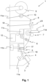
- figure 1 shows a schematic side view of a work station 1 of a textile machine 18.
- the textile machine 18 can include a large number of work stations 1.
- the work station 1 is designed as a spinning station in the present embodiment.
- the spinning station can receive a sliver 3 and produce a yarn 2 .
- Job 1 shown produces the yarn 2 from a sliver 3 .
- the yarn 2 runs through in one Delivery direction LR the job 1 and can be wound onto a coil 9.
- the work station 1 of the present exemplary embodiment has an opening unit 4 which separates individual fibers 16 from the sliver 3 .
- the individual fibers 16 are guided to a spinning rotor 5 which produces the yarn 2 from the individual fibers 16 .
- the spinning rotor 5 is arranged in a spinning box 17 in the present exemplary embodiment.
- the yarn 2 formed by the spinning rotor 5 is drawn off the spinning rotor 5 from the spinning box 17 with the aid of a pair of take-off rollers 7 , the yarn 2 still being able to pass through a first traversing device 6 which oscillates the yarn 2 .
- the yarn 2 can be traversed between the pair of take-off rollers 7 in order to reduce or delay wear on the pair of take-off rollers 7.
- the work station 1 Downstream of the pair of take-off rollers 7 in the delivery direction LR, the work station 1 has a deflection unit 8 which deflects the yarn 2 to the bobbin 9 on which it is wound.
- the work station 1 of the present exemplary embodiment has a second traversing device 20 by means of which the yarn 2 can be traversed between the deflection unit 8 and the bobbin 9 . With the help of the second traversing device 20, the yarn 2 can be wound onto a width of the bobbin 9.
- the spool 9 can be driven by a spooling roller 10 which bears against the spool 9 and drives the spool 9 via friction between the spool 9 and the spooling roller 10 .
- the coil 9 itself can also have a drive.
- a thread monitor 19 is arranged between the pair of take-off rollers 7 and the deflection unit 8, with the aid of which the presence of the thread 2 can be monitored.
- the opening unit 4, the spinning rotor 5, the first traversing device 6, the pair of take-off rollers 7, the deflection unit 8, the second traversing device 20, the coil 9, the winding roller 10 and the thread monitor 19 are treatment means according to the present embodiment, with which the fiber material is processed in the work station 1.
- the opening unit 4 changes a shape of the fiber material.
- the opening unit 4 separates individual fibers 16 from a sliver 3 .
- the spinning rotor 5 can process the individual fibers 16 into a yarn 2 .
- the first traversing device 6 and/or the second traversing device 20 moves the yarn 2 laterally to the delivery direction LR.
- the work station 1 has at least one drive 11 .
- the work station 1 has a plurality of drives 11a - 11f, with the treatment means, which according to the present exemplary embodiment being the opening unit 4, the spinning rotor 5, the first traversing device 6, the take-off roller pair 7, the second traversing device 20 and the winding roller 10, one drive 11a - 11f each (the drive 11f assigned to the second traversing device 20 is in figure 3 shown) is assigned.
- the treatment means 4, 5, 6, 7, 10, 20 can thus be driven individually and independently of one another with the aid of the associated drives 11a-11f.
- the work station 1 can advantageously have a controller 12 which can be connected to the at least one drive 11a - 11f by means of a connection (not shown here) in order to control it and thereby be able to carry out the manufacturing process of the yarn 2 .
- a load variable of the at least one drive 11a - 11f of the workplace 1 is measured according to the invention.
- the load variable is a load angle ⁇ of a drive 11a-11f.
- the functional status can be, for example, a malfunction, a blockage, a productivity, a Service life, wear and/or probability of failure of the drive 11a-11f and/or a treatment agent 4, 5, 6, 7, 10, 20. Based on the functional status of a drive 11a-11f and/or a treatment means 4, 5, 6, 7, 10, 20, the functional status of the work station 1 can be inferred.
- a restriction for example, of a functional status of a drive 11a - 11f and/or a treatment means 4, 5, 6, 7, 10, 20 leads to a restriction of the functional status of the entire workplace 1.
- slower operation of the resolution unit 4 can be a limiting factor in the functional status of the work station 1 .
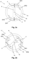
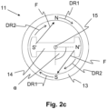
- FIG. 2a - 2c the load angle ⁇ is shown.
- the load angle ⁇ is defined as the angle between a stator field and a rotor field N - S of an electric motor.
- the drives 11a - 11f can thus be electric drives, in particular electric motors.
- Figures 2a - c show schematic cross sections of an electric drive 11 with a stator 13 and a rotor 14. According to the Figures 2a - 2c the rotor 14 is rotatable about an axis of rotation 15 . At least when the drive 11 is in operation, the stator 13 forms the stator field N ⁇ S, which is formed in the stator 13 by way of example.
- the rotor 14 also forms the rotor field N'-S ⁇ , at least during operation of the drive 11, which is formed here, for example, between the north pole N' of the rotor field N'-S ⁇ and the south pole S ⁇ of the rotor field N'-S'.
- the two fields affect each other, so that the drive 11 can apply a torque.
- the north pole N and the south pole S of the stator field N-S can rotate in the direction of rotation DR1 when the drive 11 is in operation.
- the north pole N and the south pole S are always offset from one another by 180°, so that they always move in the same way in the direction of rotation DR1. Consequently, the same reference DR1 is assigned to the two arrows assigned to the north pole N and the south pole S.
- the rotor 14 can also be set in rotation by means of a generated rotation of the stator field N-S in the direction of rotation DR1.
- the magnetic force F is formed between the south pole S and the north pole N' and the north pole N and the south pole S ⁇ .
- the rotor 14 then rotates in the direction of rotation DR2.
- the load angle ⁇ between the stator field N - S and the rotor field N' - S' is 0°, since the south pole S and the north pole N' and the north pole N and the south pole S' are not angularly offset from one another. This is the case during operation of the drive 11 when the drive 11 is unloaded. Without a load, the rotor 14 can always follow the rotating stator field N-S.
- FIG 2b an example is shown in which the drive 11 is loaded. A load therefore acts on the drive 11 .
- the north pole N and the south pole S of the stator field N - S are opposite Figure 2a keeps rotating.
- the stator field N - S leads the rotor field N' - S'. Since a load acts on the rotor 14, this inhibits the rotation of the rotor 14.
- the load brakes the rotor 14.
- the rotor 14 lags behind the stator field N-S, so that the load angle ⁇ is now in the range of approximately 45°.
- the load angle ⁇ of approximately 45° also causes the magnetic force F and the rotor 14 to be at an angle to one another, so that a torque due to the magnetic force F acts on the rotor 14 due to the law of the lever.
- the drive 11 can move the load applied to it.
- Figure 2c shows an embodiment in which the load angle ⁇ is approximately 90°.
- the rotor field N' - S' leads the stator field N - S with respect to the drive 11 according to FIG Figure 2b even further after.
- a load angle ⁇ With such a load angle ⁇ , a maximum torque can be transmitted to the rotor 14 .
- the load angle ⁇ of 90° there is a risk that the drive 11 will tilt if the load angle ⁇ is greater than 90°. As a result, the drive 11 can stop, so that the work station 1 can thereby be put out of operation.
- a functional status of a drive 11 and/or a treatment means 4, 5, 6, 7, 10, 20 can be determined with the aid of the measurement of the load angle ⁇ .
- the load angle ⁇ also depends on the load applied to the drive 11 .
- the functional status of the drive 11 and/or the treatment means 4, 5, 6, 7, 10, 20 driven by the drive 11 can be inferred based on the load and/or a load profile over time.
- the opening unit 4 can block, so that the rotor 14 no longer rotates.
- the stator field N - S continues to rotate, so that the load angle ⁇ changes constantly.
- the change in the load angle ⁇ is the same as the rotational frequency of the stator field N ⁇ S. If this is measured, it can be concluded that the release unit 4 is blocked and that this functional status is present.
- a quantity of the yarn 2 wound up on the bobbin 9 can also be measured as a functional status.
- a moment of inertia of the bobbin 9 increases.
- the drive 11e of the winding roller 10 is increasingly loaded, so that the load angle ⁇ also increases with the amount of yarn 2 on the bobbin 9 .
- the amount of yarn 2 on the bobbin 9 can be determined as a function status. In this way, in particular, an increase over time in the amount of yarn 2 on the spool 9 can also be determined. This allows conclusions to be drawn about the productivity of job 1, for example.
- a reference profile of the load size of at least one drive 11a - 11f is created from the measurement of the load size.
- the reference profile can then be compared with a load size profile that is recorded during operation of worksite 1.
- the load size profile can be continuously recorded over a time interval.
- the load magnitude profile may include changes in load magnitude and/or the magnitudes of load magnitudes.
- the load size profile can also be evaluated statistically.
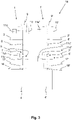
- figure 3 shows a textile machine 18 with at least two work stations 1, 1 'in a front view.
- the two jobs 1, 1 ' have each other and to figure 1 share the same features, so they will not be explained further.
- work station 1' the elements are provided with primed reference numbers.
- the load size of a drive 11a-11f of the first work station 1 can be compared with the load size of the corresponding drive 11a'-11f' of the second work station 1'.
- the load magnitude of the drive 11e of the winding roller 10 can be compared to the load magnitude of the drive 11e' of the winding roller 10'. This allows for differences between the spools 10, 10' or between the spools 9, 9'.
- the load sizes and/or load size profiles of the drives of the spinning rotors can also be measured. In this way, for example, a difference in the productivity or in the wear of the two spinning rotors can be determined.
Landscapes
- Engineering & Computer Science (AREA)
- Textile Engineering (AREA)
- Mechanical Engineering (AREA)
- Quality & Reliability (AREA)
- Spinning Or Twisting Of Yarns (AREA)
- Filamentary Materials, Packages, And Safety Devices Therefor (AREA)
Description
- Die vorliegende Erfindung betrifft ein Verfahren zum Ermitteln eines Funktionsstatus an einer Arbeitsstellen einer Textilmaschine, insbesondere einer Offenend- oder Luftspinnmaschine, wobei die Textilmaschine eine Vielzahl an Arbeitsstellen umfasst, und wobei jeweils eine Arbeitsstelle zumindest einen Antrieb umfasst, mit dessen Hilfe ein dem Antrieb zugeordnetes Behandlungsmittel der jeweiligen Arbeitsstelle zum Behandeln eines Fasermaterials betrieben wird. Des Weiteren betrifft die Erfindung eine Textilmaschine zum Durchführen eines Verfahrens zum Ermitteln des Funktionsstatus an einer Arbeitsstelle.
- Aus der
EP 2 309 043 A1 ist eine Spinnereimaschine mit mindestens einem Sensor bekannt, der einen Betriebszustand der Spinnereimaschine abfühlt und ein diesen Betriebszustand charakterisierendes Signal abgibt. Ferner ist mindestens ein Aktor vorgesehen, dem dieses Signal zugeleitet wird und der nach Maßgabe dieses Signals eine Maßnahme einleitet. Allerdings ist die Messung des Betriebszustandes mittels des Sensors nachteilig, da dieser ein zusätzliches, kostenverursachendes, Bauteil darstellt. - Aus der
DE 29 50 063 A1 ist eine Überwachungsschaltung zum Erfassen von Betriebsstörungen bei einer Textilmaschine bekannt, die mindestens eine Vielzahl von Arbeitsorganen aufweisende Arbeitsorgangruppe aufweist, deren Arbeitsorgane je einer Arbeitsstelle zugeordnet und unter sich gleich sind und durch je einen Einzelantrieb mit je einem Elektromotor antreibbar sind. Die Betriebsstörungen werden dabei dadurch erfasst, dass eine Phasenlage eines Motorstroms mit einem Bezugssignal verglichen wird. Das Bezugssignal gilt dabei für die Vielzahl an Einzelantrieben gleichermaßen. - Aus der
DE 42 28 300 A1 ist ein Verfahren zur Überwachung von Spinnstellen einer Spinnmaschine, insbesondere einer Ringspinnmaschine, bekannt. An den Spinnstellen sind Spindeln angeordnet, auf die das produzierte Garn aufgewickelt wird. Das Verfahren ist dadurch gekennzeichnet, dass während der Anlaufphase, der Betriebsphase und der Auslaufphase zumindest eines die Spindeln antreibenden Motors mindestens an einem Teil der Spinnstelle zumindest zeitweise unmittelbar die Drehzahl der Spindel oder die Leistungsaufnahme des Spindelmotors als repräsentativer Istwert ermittelt wird. Dieser Istwert wird jeweils mit einem vorgebbaren, gemäß einem vorgegebenen Drehzahlprogramm zeitlich variabler Sollwert verglichen. Bei Abweichung des Istwerts vom Sollwert und einen vorgegebenen oberen Schwellenwert nach oben oder einen vorgegebenen unteren Schwellenwert nach unten wird abhängig von der Art der Abweichung eine Klassifizierung der Störung im einen Fall als Fadenbruch oder Schnelllauf bzw. im anderen Fall als Schleichlauf vorgenommen und ein entsprechendes Alarmsignal ausgelöst. - Aus der
DE 44 04 243 A1 ist ein Verfahren und eine Einrichtung zum Betreiben einer Offenend-Rotorspinneinheit mit einzelmotorischem elektrischem Antrieb des Spinnrotors bekannt. Die dem Antrieb zugeführte elektrische Energie wird überwacht. Der Istwertverlauf einer die Energiezufuhr repräsentierenden Größe wird mit dem der jeweiligen Betriebsphase zugeordneten Sollwertverlauf verglichen. Bei Überschreiten von Grenzwerten der Abweichung der Istwerte dieser die Energiezufuhr repräsentierenden Größe von deren Sollwerten wird der Antrieb abgeschaltet. Bei einem Grenzwert kann es sich um einen Maximalwert handeln, dessen kurzzeitiges Überschreiten zum Abschalten führt. Allerdings kann es sich auch um einen darunterliegenden Wert handeln, dessen Überschreiten während einer festlegbaren Zeitdauer ebenfalls zum Abschalten führt. Bei transienten Motorzuständen wird vorteilhaft die Überwachung durch Integralbildung mit zunehmendem Integrationsbereich vom Startpunkt an realisiert. Zusätzlich zum Abschalten des Antriebes kann in Abhängigkeit von verschiedenen Bedingungen ein Alarmsignal generiert werden. Als die Energiezufuhr repräsentierende Größe ist vorteilhaft die Stromaufnahme einzusetzen, die sehr deutlich die störungsbedingte von Sollwerten abweichende Lastzunahme beim Rotorantrieb kennzeichnet. - Aus der
DE 10 2010 009 164 A1 ist ein Verfahren und Vorrichtung zum Steuern einer Textilmaschine oder eines angetriebenen Teils einer Textilmaschine bekannt. Beim Verfahren zum Erkennen des Betriebszustandes einer Textilmaschine oder eines angetriebenen Teiles einer Textilmaschine, insbesondere einer Spinnmaschine bzw. Spinnstelle, wobei ein bewegliches Teil der Textilmaschine von einem Elektromotor direkt oder über eine mechanische Schnittstelle angetrieben wird, wobei dieser mittels einer Stelleinheit angesteuert wird, und dass mindestens ein Betriebsparameter des Elektromotors und/oder der Stelleinheit gemessen und ausgewertet wird dahingehend, dass mindestens eine anlagenbezogene oder motorabnutzungsbezogene Zustandsgröße ermittelt wird. - Aufgabe der vorliegenden Erfindung ist es somit, den Nachteil des Stands der Technik zu beheben.
- Die Aufgabe wird gelöst durch ein Verfahren zum Ermitteln eines Funktionsstatus an einer Arbeitsstelle einer Textilmaschine sowie einer Textilmaschine mit den Merkmalen der unabhängigen Patentansprüche.
- Vorgeschlagen wird ein Verfahren zum Ermitteln eines Funktionsstatus an einer Arbeitsstelle einer Textilmaschine. Bei der Textilmaschine kann es sich beispielsweise um eine Offenendspinnmaschine oder eine Luftspinnmaschine handeln. Der Funktionsstatus an der Arbeitsstelle kann beispielsweise ein Verschleiß, eine Fehlfunktion, eine Blockierung, eine Ausfallwahrscheinlichkeit, eine Produktivität und/oder eine Lebensdauer sein. Beispielsweise kann die Blockierung zwischen beweglichen Komponenten der Arbeitsstelle auftreten. Ebenso kann der Funktionsstatus ein Betriebszustand eines Behandlungsmittels sein.
- Die Textilmaschine umfasst außerdem eine Vielzahl an Arbeitsstellen, so dass die Produktivität der Textilmaschine gemäß der Anzahl an Arbeitsstellen vervielfacht ist.
- Jeweils eine Arbeitsstelle weist ferner zumindest einen Antrieb auf, mit dessen Hilfe zumindest ein dem Antrieb zugeordnetes Behandlungsmittel der jeweiligen Arbeitsstelle zum Behandeln eines Fasermaterials betrieben wird. Die Behandlungsmittel behandeln das Fasermaterial auf eine Weise, dass die Arbeitsstelle ihr End- oder Zwischenprodukt herstellen kann. Die Behandlungsmittel können dabei Baueinheiten, Hilfsmittel und/oder Vorrichtungen sein, die das Fasermaterial verarbeiten oder weiterleiten. Beispielsweise kann die Arbeitsstelle eine Karde sein, die ungerichtete einzelne Fasern zu einem Faservlies verarbeiten kann. Das Behandlungsmittel kann in diesem Fall beispielsweise eine Walze sein, die vom Antrieb in Drehung gesetzt wird, um die ungerichteten Fasern auszurichten.
- Das Fasermaterial kann aber auch ein Faserband sein, das in einer Spinnstelle zuerst von einem Behandlungsmittel, beispielsweise einer Auflöseeinheit, in einzelne Fasern aufgelöst wird, welche anschließend von einem Behandlungsmittel in Gestalt eines Spinnrotors zu einem Garn versponnen werden. Der Antrieb kann dabei die Auflöseeinheit oder den Spinnrotor antreiben.
- Die Arbeitsstelle kann aber auch eine Umspuleinheit sein, mittels der ein Garn von einer Spule auf eine andere Spule umgespult wird.
- Erfindungsgemäß wird anhand einer Messung einer Lastgröße des zumindest einen Antriebs zumindest der Funktionsstatus zumindest eines Behandlungsmittels ermittelt. Zusätzlich oder alternativ kann auch ein Funktionsstatus eines Antriebs ermittelt werden. Zusätzlich oder alternativ kann aus dem Funktionsstatus des Behandlungsmittels und/oder des Antriebs auf einen Funktionsstatus der Arbeitsstelle geschlossen werden. Bei einem Funktionsstatus, der beispielsweise angibt, dass ein Spinnrotor nicht zu 100% funktionsfähig ist, ist der Funktionsstatus der Arbeitsstelle ebenfalls eingeschränkt. Ist der Funktionsstatus ein Betriebszustand eines Behandlungsmittels, so kann mittels der Messung der Lastgröße festgestellt werden, ob das Behandlungsmittel, insbesondere die Auflöseeinheit, bzw. die Arbeitsstelle sich im regulären Betrieb oder im Ansetzbetrieb befindet.
- Insbesondere kann der Funktionsstatus des Antriebs ermittelt werden, an dem die Lastgröße gemessen wird. Die Lastgröße ist erfindungsgemäß ein Lastwinkel des zumindest einen Antriebs. Der Lastwinkel ist bei einem elektrischen Antrieb definiert als ein Winkel zwischen einem Statorfeld und einem Rotorfeld des Antriebs. Mittels der Messung der Lastgröße kann ein Verhalten des Antriebs ermittelt werden, so dass dieses genauer erfasst werden kann. Insbesondere kann die Lastgröße, nämlich der Lastwinkel, mit Hilfe eines Stroms, einer Spannung und/oder mittels der zeitlichen Verläufe des Stroms und/oder der Spannung des Antriebs ermittelt werden. Die Messung der Lastgröße kann damit insbesondere sensorlos durchgeführt werden. Die Messung der Lastgröße kann dadurch zuverlässig und präzise erfolgen.
- Der Lastwinkel ist der Winkel zwischen dem Statorfeld und dem Rotorfeld des elektrischen Antriebs. Bei einem unbelasteten Antrieb beträgt der Lastwinkel 0°, wohingegen der Lastwinkel bei einer steigenden Last größer wird. Bei dem Lastwinkel von 0° sind das Statorfeld und das Rotorfeld antiparallel zueinander orientiert. Ist der Antrieb dagegen belastet, steigt der Lastwinkel, so dass daraus auf den Funktionsstatus geschlossen werden kann. Mit Hilfe des Lastwinkels können somit Rückschlüsse auf die am Antrieb angreifende Last gewonnen werden. Außerdem kann mittels einer Änderung des Lastwinkels auf Änderungen der Last am Antrieb geschlossen werden. Verklemmt sich beispielsweise der Antrieb der Arbeitsstelle, steigt der Lastwinkel. Aus diesen Informationen kann auf die Verklemmung geschlossen werden, so dass der Funktionsstatus ermittelt ist.
- In einer vorteilhaften Weiterbildung der Erfindung wird die Lastgröße zumindest am Antrieb gemessen, der einem Behandlungsmittel in Form einer Auflöseeinheit, einem Spinnrotor, einer Changiereinrichtung, einem Abzugswalzenpaar, einer Spule und/oder einer Spulwalze zugeordnet ist. Dadurch können die Funktionsstatus der angetriebenen Behandlungsmittel der Arbeitsstelle ermittelt werden.
- Von Vorteil ist es, wenn anhand der Messung der Lastgröße ein Blockieren, ein Verschleiß, eine Ausfallwahrscheinlichkeit, eine Lebensdauer und/oder ein Wartungsintervall eines Behandlungsmittels und/oder eines Antriebs ermittelt werden. Beispielsweise durch das Erkennen des Verschleißes kann ein Austausch des Behandlungsmittels geplant werden. Anhand der Ausfallwahrscheinlichkeit oder der Lebensdauer kann geplant werden, wieviel der Behandlungsmittel für einen zukünftigen Austausch bereitgehalten werden sollten. Anhand der Wartungsintervalle kann ein Wartungsplan der Arbeitsstelle und/oder der Textilmaschine geplant werden. Wenn der Verschleiß auftritt bzw. sich verstärkt, kann sich beispielsweise ein Behandlungsmittel schwergängiger bewegen, so dass der dem Behandlungsmittel zugeordneten Antrieb stärker belastet wird und die Lastgröße, nämlich der Lastwinkel, steigt. Anhand dieser Messung kann auf den Verschleiß geschlossen werden.
- Zusätzlich oder alternativ kann anhand der Messung der Lastgröße eine Produktivität der Arbeitsstelle ermittelt werden. Dadurch können Produktionskosten für ein Endprodukt kalkuliert werden. Dadurch können beispielsweise Arbeitsstellen mit einer geringen Produktivität besonders behandelt werden, indem sie beispielsweise abgeschaltet oder intensiver gewartet werden. Weist die Arbeitsstelle eine hohe Produktivität auf, ist zumindest ein Antrieb höher belastet, so dass sich die Lastgröße ändert. Insbesondere sind, wenn die Arbeitsstelle eine hohe Produktivität aufweist, alle Antriebe der Arbeitsstelle gleichermaßen höher belastet, so dass daraus auf die erhöhte Produktivität geschlossen werden kann.
- Zusätzlich oder alternativ kann anhand der Messung der Lastgröße die Anwesenheit des Fasermaterials in der Arbeitsstelle ermittelt werden. Wenn ein Antrieb des Behandlungsmittels oder mehrere, insbesondere alle, Antriebe der Behandlungsmittel der Arbeitsstelle unbelastet ist/sind, ist die Lastgröße bzw. die Lastgrößen der Antriebe beispielsweise in Form des Lastwinkels im Wesentlichen Null bzw. im Leerlauf der Antriebe zumindest wesentlich geringer als bei belasteten Antrieben, wobei dies ein Hinweis auf die Nicht-Anwesenheit bzw. der Abwesenheit des Fasermaterials sein kann. Beispielsweise kann es an garnproduzierenden Arbeitsstellen vorkommen, dass ein in einer Kanne bevorratetes Faserband zur Herstellung eines Garns zu Neige gegangen ist, so dass infolgedessen die Produktion von Garn unterbrochen ist, die Antriebe der Arbeitsstelle aber noch weiter die Behandlungsmittel betreiben. Ist das Fasermaterial erschöpft, kann dies anhand des kleineren Lastwinkels bzw. der abrupten Änderung des Lastwinkels erkannt werden und die Arbeitsstelle abgeschaltet und/oder eine entsprechende Mitteilung abgesetzt werden, um Energie einzusparen oder ein Betriebspersonal auf ein Nachfüllen des Fasermaterials aufmerksam zu machen. Zudem kann auch ein übermäßiger Verschleiß der leer laufenden Behandlungsmittel, insbesondere der Speisewalze, vermieden werden. Ebenso kann beim Anspinnen erkannt werden, ob ein Fasermaterial vorhanden ist und bei fehlendem Fasermaterial der Antrieb sowohl der Auflöseeinheit als auch der Speiseeinheit der Spinnstelle gestoppt werden. Hierdurch kann ein unnützer Anspinnvorgang vermieden werden.
- Weiterhin ist es von Vorteil, wenn das Blockieren eines Behandlungsmittels vor Erreichen einer Endposition, einer Stoppposition und/oder einer Anschlagposition des Behandlungsmittels ermittelt wird. Da das Blockieren des Behandlungsmittels ein ähnlicher Zustand wie das Erreichen der Endposition, der Stoppposition und/oder der Anschlagposition ist, kann es vorteilhaft sein, das Blockieren vor dem Erreichen der entsprechenden Position zu erkennen, um es nicht mit dem Erreichen der Endposition, der Stoppposition und/oder mit der Anschlagposition zu verwechseln. Beispielsweise kann es sich bei dem Behandlungsmittel um eine Changiereinrichtung handeln, die zwischen zwei Endpositionen hin und her changiert. In den Endpositionen kehrt sich die Changierrichtung der Changiereinrichtung um, so dass in den Endpositionen eine spezifischer Verlauf bzw. Änderung der Lastgröße auftritt, der/die in beiden Endpositionen zumindest ähnlich ist. Aus einem Vergleich des Verhaltens der Lastgröße bei Blockierung und dem Verhalten der Lastgröße in den Endpositionen kann auf das Blockieren zwischen den Endpositionen geschlossen werden.
- Vorteilhaft ist es ebenso, wenn ein Überschreiten der Lastgröße über einen Grenzwert erkannt wird. Dadurch kann der Antrieb vor Fehlfunktionen oder Beschädigungen, beispielsweise durch Überlastung, geschützt werden. Insbesondere kann für den Lastwinkel ein Grenzwert von 90° gewählt werden, da ab diesem Lastwinkel der Antrieb kippt und stehen bleiben kann. Zusätzlich oder alternativ kann auch ein Unterschreiten eines Grenzwerts der Lastgröße erkannt werden. Damit kann darauf geschlossen werden, dass eine Belastung des Antriebs unterschritten ist.
- Ferner ist es von Vorteil, wenn aus der Messung der Lastgröße ein Lastgrö-βenprofil erstellt wird. Um das Lastgrößenprofil zu erstellen, kann die Lastgröße beispielsweise in einem Zeitintervall gegen die Zeit aufgetragen werden. Mittels eines Lastgrößenprofils, das in einem vergleichsweise geringen Zeitintervall, beispielsweise einigen Sekunden, den Lastgrößenverlauf beschreibt, können beispielsweise Änderungen im Funktionsstatus eines Behandlungsmittels erkannt werden, die relativ abrupt auftreten. Damit können beispielsweise Blockierungen erkannt werden, die im Wesentlichen innerhalb weniger Sekunden entstehen. Bei der Blockierung ändert sich die Lastgröße relativ schnell, so dass die Erstellung des Lastgrößenprofils in dem geringen Zeitintervall ausreicht. Wird das Lastgrößenprofil somit lediglich innerhalb weniger Sekunden erstellt, können derartige Fehler, wie Blockierungen oder das Fehlen des Fasermaterials, erkannt werden.
- Zusätzlich oder alternativ kann das Lastgrößenprofil auch über einen längeren Zeitraum bzw. in einem längeren Zeitintervall erstellt werden. Die Länge des Zeitraums hängt dabei von der Art des Funktionsstatus ab, der ermittelt werden soll. Beispielsweise kann, wenn ein Verschleiß eines Behandlungsmittels erkannt werden soll, das Lastgrößenprofil über einen Zeitraum erstellt werden, bei dem der Verschleiß merkliche Auswirkungen auf die Lastgröße hat. Ein derartiger Zeitraum kann durchaus einige Tage bis Wochen betragen. Über diesen langen Zeitraum kann sich aufgrund des Verschleißes die Lastgröße verändern, was anhand des Lastgrößenprofils, das über mehrere Tage bis Wochen aufgenommen wurde, erkannt werden kann.
- Das Lastgrößenprofil kann dabei kontinuierlich erstellt werden, so dass der Funktionsstatus des Behandlungsmittels und/oder des Antriebs lückenlos überwacht wird. Außerdem kann das Lastgrößenprofil auch in bestimmten Zeitintervallen erstellt werden, so dass ein Mess- und/oder Rechenaufwand für den Vergleich vergleichsweise gering ist.
- Vorteilhaft ist es, wenn aus der Messung der Lastgröße wenigstens ein Referenzwert, vorzugsweise ein Referenzprofil, der Lastgröße des Antriebs erstellt wird. Es kann somit beispielsweise ein Referenzprofil des Spinnrotorantriebs erstellt werden. Das Referenzprofil kann über einen bestimmten Zeitraum aufgenommen werden. Das Referenzprofil wird vorzugsweise dann erstellt, wenn ein normaler Funktionsstatus, d.h. wenn keine Fehlfunktion o.ä., vorliegt. Das Referenzprofil gibt den Verlauf des Lastwinkels über die Zeit an. Mit Hilfe des Referenzwerts bzw. Referenzprofils ist ein Vergleich zu einem normalen Betrieb der Arbeitsstelle möglich. Ebenso kann, um beispielsweise das Vorhandensein des Fasermaterials zu erkennen, ein Referenzwert für die Lastgröße des Antriebs der Auflöseeinheit erstellt werden. Der Referenzwert kann ebenfalls dann erstellt werden, wenn ein normaler Funktionsstatus vorliegt, d.h. ein Fasermaterial an der Arbeitsstelle vorhanden ist.
- Von Vorteil ist es, wenn der Referenzwert bzw. das Referenzprofil während einer ersten Startphase der Arbeitsstelle erstellt wird. Zusätzlich oder alternativ kann der Referenzwert oder das Referenzprofil auch während einer ersten Startphase des Antriebs und/oder des Behandlungsmittels erstellt werden. Die erste Startphase ist nach einer Fertigstellung der Arbeitsstelle, während alle Komponenten der Arbeitsstelle noch bestimmungsgemäß funktionieren, d.h. die Behandlungsmittel weisen im Allgemeinen keinen Verschleiß o.ä. auf und sind beispielsweise nicht blockiert. Die Arbeitsstelle weist somit noch keinen Verschleiß, keine Fehlfunktionen, die höchste Lebensdauer und die geringste Ausfallwahrscheinlichkeit auf. Ein währenddessen erstelltes Referenzprofil bildet somit den bevorzugten Funktionsstatus der Arbeitsstelle ab.
- Einen Referenzwert während der ersten Startphase eines Behandlungsmittels zu erstellen, kann beispielsweise sinnvoll sein, um das Vorhandensein des Fasermaterials oder ggf. auch eines Fadens in dem Behandlungsmittel festzustellen. Beispielsweise kann ein Referenzwert für den Antrieb der Auflöseeinheit unmittelbar nach dem Beginn des Anspinnvorgangs erstellt werden, wenn die Faserspeisung noch nicht begonnen hat und sich die Auflöseeinheit somit noch im Leerlauf befindet, ohne Fasermaterial auszukämmen. Ggf. kann der Referenzwert sogar bereits während des Vorspeisens erstellt werden.
- Der Referenzwert bzw. das Referenzprofil kann vorteilhafterweise mit der aktuell gemessenen Lastgröße bzw. dem aufgenommenen Lastgrößenprofil verglichen werden. Die aktuell gemessene Lastgröße bzw. das Lastgrößenprofil spiegelt dabei den aktuellen Funktionsstatus des Antriebs und/oder des Behandlungsmittels wieder. Mit Hilfe des Vergleichs des Lastgrößenprofils mit dem Referenzprofil können Unterschiede zwischen dem momentanen Funktionsstatus und dem Funktionsstatus, während eines Zeitpunkts, zum dem der Antrieb, das oder die Behandlungsmittel und/oder die Arbeitsstelle bestimmungsgemäß funktionierten, ermittelt werden. Liegt beispielsweise in o.g. Beispiel der Auflöseeinheit nach dem Start der Fasereinspeisung bzw. im laufenden Spinnbetrieb der aktuell gemessene Wert der Lastgröße über dem zuvor ermittelten Referenzwert, so wird davon ausgegangen, dass das Faserband vorhanden ist und das Anspinnen bzw. der reguläre Spinnprozess wird fortgesetzt. Wird hingegen festgestellt, dass der Wert der Lastgröße gleich dem zuvor ermittelten Referenzwert ist, so wird daraus auf das Fehlen des Faserbandes geschlossen und das Anspinnen abgebrochen bzw. im Falle einer laufenden Arbeitsstelle die betreffende Arbeitsstelle stillgesetzt.
- Von Vorteil ist es auch, wenn ein Verlauf des Lastgrößenprofils des Antriebs mit einer momentanen Position des vom Antrieb angetriebenen Behandlungsmittels der Arbeitsstelle verglichen wird. Zusätzlich oder alternativ kann der Verlauf des Lastgrößenprofils des Antriebs auch mit einer momentanen Drehstellung des vom Antrieb angetriebenen Behandlungsmittels der Arbeitsstelle verglichen werden. Das angetriebene Behandlungsmittel der Arbeitsstelle kann beispielsweise die Changiereinrichtung sein, so dass mit Hilfe des Vergleichs des Verlaufs des Lastgrößenprofils mit der momentanen Position ein Versatz zwischen einer Soll-Position und einen Ist-Position der Changiereinrichtung erkannt werden kann. Der Verlauf des Lastgrößenprofils weist, wenn beispielsweise die Changiereinrichtung vom Antrieb angetrieben ist, insbesondere in Umkehrpunkten der Changiereinrichtung einen spezifischen Verlauf auf. Anhand eines Vergleichs einer momentanen Position der Changiereinrichtung kann auf einen Unterschied zwischen Soll- und Ist-Position geschlossen werden.
- Des Weiteren ist es vorteilhaft, wenn die Lastgröße eines Antriebs einer ersten Arbeitsstelle mit der Lastgröße des entsprechenden Antriebs einer zweiten Arbeitsstelle verglichen wird. Zusätzlich oder alternativ kann auch das Lastgrößenprofil des Antriebs der ersten Arbeitsstelle mit dem Lastgrößenprofil des entsprechenden Antriebs der zweiten Arbeitsstelle verglichen werden. Es können somit beispielsweise die Lastgrößen und/oder das Lastgrö-βenprofile der Antriebe der Spinnrotoren der beiden Arbeitsstellen miteinander verglichen werden. Dadurch können die Funktionsstatus der beiden Arbeitsstellen verglichen werden. Beispielsweise kann damit erkannt werden, welcher der beiden Spinnrotoren der beiden Arbeitsstellen eine höhere Produktivität aufweist. Weist der Spinnrotor der ersten Arbeitsstelle beispielsweise eine höhere Produktivität als der Spinnrotor der zweiten Arbeitsstelle auf, ist der Antrieb des einen Spinnrotors stärker belastet als der Antrieb des anderen Spinnrotors. Dadurch sind die Lastgrößen der beiden den Spinnrotoren zugeordnete Antriebe unterschiedlich, so dass daraus auf die Produktivität der Arbeitsstellen bzw. den Unterschied der Produktivitäten der beiden Arbeitsstellen geschlossen werden kann. Ferner kann beispielsweise der Verschleiß der beiden Spinnrotoren erkannt werden, da die beiden Lastgrö-βen und/oder die Lastgrößenprofile in diesem Fall voneinander abweichen. Insbesondere kann die Abweichung der beiden Lastgrößen und/oder der Lastgrößenprofile der beiden Antriebe miteinander verglichen werden. Zusätzlich oder alternativ können auch die Antriebe von mehr als zwei Arbeitsstellen verglichen werden. Es können dabei lediglich die Antriebe miteinander verglichen werden, die einem bestimmten Behandlungsmittel zugeordnet sind. Beispielsweise können die Lastgrößen und/oder die Lastgrößenprofile eines Teils der Antriebe der Spinnrotoren der Textilmaschine oder gar die Lastgrößen und/oder die Lastgrößenprofile aller Antriebe der Spinnrotoren einer Textilmaschine miteinander verglichen werden. Dadurch kann beispielsweise ermittelt werden, welcher Spinnrotor die höchste Produktivität oder beispielsweise den geringsten Verschleiß aufweist. Sind beispielsweise alle Antriebe der ersten Arbeitsstelle höher belastet als alle Antriebe der zweiten Arbeitsstelle, kann dies ein Hinweis darauf sein, dass die erste Arbeitsstelle eine höhere Produktivität aufweist als die zweite Arbeitsstelle.
- Von Vorteil ist es auch, wenn die Lastgröße zumindest eines ersten Antriebs einer Arbeitsstelle mit einer Lastgröße eines zweiten Antriebs derselben Arbeitsstelle verglichen wird. Zusätzlich oder alternativ kann auch das Lastgrö-βenprofil zumindest des ersten Antriebs der Arbeitsstelle mit dem Lastgrö-βenprofil des zweiten Antriebs derselben Arbeitsstelle verglichen werden. Die beiden Antriebe bzw. die mit den Antrieben betriebenen Behandlungsmittel können beispielsweise in einer Lieferrichtung eines Garns, insbesondere unmittelbar, hintereinander angeordnet sein. Dadurch kann beispielsweise eine Fehlfunktion ermittelt werden, die zwischen diesen beiden Antrieben auftritt. Zusätzlich oder alternativ können auch die Lastgrößen und/oder Lastgrößenprofile mehrerer Antriebe einer Arbeitsstelle miteinander verglichen werden.
- Wenn die Lastgröße eines Antriebs statistisch ausgewertet wird, bringt dies ebenfalls Vorteile mit sich. Zusätzlich oder alternativ kann auch das Lastgrö-βenprofil statistisch ausgewertet werden. Beispielsweise kann aus einer kontinuierlichen, insbesondere stetigen, Änderung der Lastgröße und/oder des Lastgrößenprofil auf einen Verschleiß geschlossen werden, so dass die Änderung der Lastgröße gemessen werden kann. Es kann somit beispielsweise eine Steigung (positiv oder negativ) über die Zeit ermittelt werden. Dabei kann beispielsweise eine Standardabweichung, eine Varianz und/oder eine statistische Verteilung, insbesondere eine Gauß-Verteilung, der Lastgröße ausgewertet werden.
- Vorteilhaft ist es, wenn ein Mittelwert der Lastgröße ermittelt wird. Zusätzlich oder alternativ kann auch eine Schwankung der Lastgröße ermittelt werden. Ebenfalls zusätzlich oder alternativ kann auch der Mittelwert und/oder die Schwankung des Lastgrößenprofils ermittelt werden. Als Mittelwert kann beispielsweise ein zeitlicher Mittelwert gebildet werden. Vorteilhaft ist es auch, wenn bei der Schwankung deren Periodizität ermittelt wird. Die periodische Schwankung der Lastgröße kann beispielsweise bei einem Antrieb auftreten, der ein Behandlungsmittel mit einer Unwucht antreibt.
- Des Weiteren wird mit Hilfe einer Steuerung der Arbeitsstelle und/oder der Textilmaschine die Lastgröße gemessen. Zusätzlich oder alternativ können mit Hilfe der Steuerung auch der Funktionsstatus des Antriebs und/oder des Behandlungsmittels ermittelt werden. Die Steuerung kann vorzugsweise mit dem zumindest einen Antrieb verbunden sein, so dass die Steuerung den Antrieb steuern und die Lastgröße vom Antrieb erhalten oder selbst messen kann. In der Steuerung kann beispielsweise ein Auswertprogramm hinterlegt sein, das die Lastgröße, Änderungen der Lastgröße, das Referenzprofil und/oder das Lastgrößenprofil erstellt. Diese Daten können auch in der Steuerung in einem Speicher abgelegt werden oder bereits vorhanden sein. Die Steuerung kann die Lastgröße beispielsweise dadurch messen, dass diese einen Strom und/oder eine Spannung des Antriebs misst. Insbesondere kann die Steuerung die Lastgröße ermitteln, indem diese eine im Betrieb des Antriebs auftretende induzierte Spannung misst. Die Steuerung kann beispielsweise auch eine Phasenverschiebung zwischen dem Strom, der Spannung des Antriebs und der induzierten Spannung messen und daraus die Lastgröße ermitteln.
- Vorgeschlagen wird des Weiteren eine Textilmaschine, insbesondere eine Offenend- oder Luftspinnmaschine, mit einer Vielzahl an Arbeitsstellen, die jeweils zumindest einen Antrieb aufweisen. Mit Hilfe des Antriebs kann zumindest ein dem Antrieb zugeordnetes Behandlungsmittel der jeweiligen Arbeitsstelle zum Behandeln eines Fasermaterials betrieben werden. Ist die Arbeitsstelle beispielsweise eine Spinnstelle, kann das Behandlungsmittel beispielsweise eine Auflöseeinheit, ein Spinnrotor, ein Abzugswalzenpaar, eine Changiereinrichtung und/oder eine Spulwalze sein.
- Außerdem weist die Textilmaschine zumindest eine Steuerung auf, mit der zumindest ein Antrieb der Textilmaschine steuerbar ist. Zusätzlich oder alternativ kann auch eine Arbeitsstelle und/oder ein Gruppe von Arbeitsstellen die Steuerung aufweisen. Die Steuerung umfasst dabei Mittel, mit denen die Steuerung die Antriebe ansteuern kann. Die Steuerung kann auch eine Speichereinheit, um ein Steuerprogramm abzuspeichern, eine Recheneinheit, um Messwerte auszuwerten, und/oder zumindest eine Schnittstelle aufweisen, über die Steuerdaten und/oder Messdaten ausgetauscht werden können.
- Erfindungsgemäß ist die Steuerung derart ausgebildet, dass die Textilmaschine nach einem Verfahren gemäß zumindest einem Merkmal der vorangegangenen und/oder nachfolgenden Beschreibung zu betreiben.
- Weitere Vorteile der Erfindung sind in den nachfolgenden Ausführungsbeispielen beschrieben. Es zeigen:
- Figur 1
- eine schematische Seitenansicht einer Arbeitsstelle einer Offenendspinnmaschine,
- Figur 2a - c
- einen schematischen Querschnitt eines Antriebs mit Stator und Rotor, und
- Figur 3
- eine schematische Vorderansicht einer Textilmaschine mit zwei Arbeitsstellen.
-
Figur 1 zeigt eine schematische Seitenansicht einer Arbeitsstelle 1 einer Textilmaschine 18. Die Textilmaschine 18 kann dabei eine Vielzahl an Arbeitsstellen 1 umfassen. Die Arbeitsstelle 1 ist im vorliegenden Ausführungsbeispiel als eine Spinnstelle ausgebildet. Die Spinnstelle kann ein Faserband 3erhalten und ein Garn 2 herstellen. Die inFigur 1 gezeigte Arbeitsstelle 1 stellt aus einem Faserband 3 das Garn 2 her. Das Garn 2 durchläuft in einer Lieferrichtung LR die Arbeitsstelle 1 und kann auf eine Spule 9 aufgewickelt werden. - Die Arbeitsstelle 1 des vorliegenden Ausführungsbeispiels weist eine Auflöseeinheit 4 auf, die aus dem Faserband 3 einzelne Fasern 16 auslöst. Die einzelnen Fasern 16 werden zu einem Spinnrotor 5 geführt, der aus den einzelnen Fasern 16 das Garn 2 herstellt. Der Spinnrotor 5 ist im vorliegenden Ausführungsbeispiel in einer Spinnbox 17 angeordnet. Das durch den Spinnrotor 5 gebildete Garn 2 wird mit Hilfe eines Abzugswalzenpaares 7 vom Spinnrotor 5 aus der Spinnbox 17 abgezogen, wobei das Garn 2 noch eine erste Changiereinrichtung 6 passieren kann, die das Garn 2 changiert. Mit Hilfe der ersten Changiereinrichtung 6 kann das Garn 2 zwischen dem Abzugswalzenpaar 7 changiert werden, um eine Abnutzung des Abzugswalzenpaars 7 zu vermindern bzw. hinauszuzögern. In Lieferrichtung LR dem Abzugswalzenpaar 7 nachgeordnet, weist die Arbeitsstelle 1 eine Umlenkeinheit 8 auf, die das Garn 2 zur Spule 9 umlenkt, auf der es aufgewickelt wird. In Lieferrichtung LR nach der Umlenkeinheit 8 weist die Arbeitsstelle 1 des vorliegenden Ausführungsbeispiels eine zweite Changiereinrichtung 20 auf, mittels der das Garn 2 zwischen der Umlenkeinheit 8 und der Spule 9 changiert werden kann. Mit Hilfe der zweiten Changiereinrichtung 20 kann das Garn 2 auf einer Breite der Spule 9 aufgewickelt werden. Die Spule 9 kann von einer Spulwalze 10 angetrieben werden, die an der Spule 9 anliegt und über Reibung zwischen der Spule 9 und der Spulwalze 10 die Spule 9 antreibt. Zusätzlich oder alternativ kann die Spule 9 auch selbst einen Antrieb aufweisen.
- Zwischen dem Abzugswalzenpaar 7 und der Umlenkeinheit 8 ist im vorliegenden Ausführungsbeispiel ein Fadenwächter 19 angeordnet, mit dessen Hilfe eine Anwesenheit des Garns 2 überwacht werden kann.
- Die Auflöseeinheit 4, der Spinnrotor 5, die erste Changiereinrichtung 6, das Abzugswalzenpaar 7, die Umlenkeinheit 8, die zweite Changiereinrichtung 20, die Spule 9, die Spulwalze 10 und der Fadenwächter 19 sind gemäß dem vorliegenden Ausführungsbeispiel Behandlungsmittel, mit denen das Fasermaterial in der Arbeitsstelle 1 verarbeitet wird. Dabei verändert beispielsweise die Auflöseeinheit 4 eine Form des Fasermaterials. Die Auflöseeinheit 4 löst aus einem Faserband 3 einzelne Fasern 16 aus. Der Spinnrotor 5 kann die einzelnen Fasern 16 zu einem Garn 2 verarbeiten. Die erste Changiereinrichtung 6 und/oder die zweite Changiereinrichtung 20 bewegt das Garn 2 seitlich zur Lieferrichtung LR. Das Abzugswalzenpaar 7 transportiert dagegen das Garn 2 in Lieferrichtung LR.
- Des Weiteren weist die Arbeitsstelle 1 zumindest einen Antrieb 11 auf. Im vorliegenden Ausführungsbeispiel weist die Arbeitsstelle 1 mehrere Antriebe 11a - 11f auf, wobei den Behandlungsmitteln, die gemäß dem vorliegenden Ausführungsbeispiel die Auflöseeinheit 4, der Spinnrotor 5, die erste Changiereinrichtung 6, das Abzugswalzenpaar 7, die zweite Changiereinrichtung 20 und die Spulwalze 10 sind, jeweils ein Antrieb 11a - 11f (der zur zweiten Changiereinrichtung 20 zugeordnete Antrieb 11f ist in
Figur 3 gezeigt) zugeordnet ist. Die Behandlungsmittel 4, 5, 6, 7, 10, 20 können somit einzeln und unabhängig voneinander mit Hilfe der zugeordneten Antriebe 11 a - 11f angetrieben werden. - Außerdem kann die Arbeitsstelle 1 vorteilhafterweise eine Steuerung 12 aufweisen, die mittels einer hier nicht gezeigten Verbindung mit dem zumindest einen Antriebe 11a - 11f verbunden sein kann, um diesen zu steuern und um dadurch den Herstellungsprozess des Garns 2 ausführen zu können.
- Um einen Funktionsstatus der Arbeitsstelle 1 ermitteln zu können, wird erfindungsgemäß eine Lastgröße des zumindest einen Antriebs 11a - 11f der Arbeitsstelle 1 gemessen. Die Lastgröße ist erfindungsgemäß ein Lastwinkel α eines Antriebs 11a - 11f. Der Funktionsstatus kann beispielsweise eine Fehlfunktion, eine Blockierung, eine Produktivität, eine Lebensdauer, ein Verschleiß und/oder eine Ausfallwahrscheinlichkeit des Antriebs 11a - 11f und/oder eines Behandlungsmittels 4, 5, 6, 7, 10, 20 sein. Anhand des Funktionsstatus eines Antriebs 11a - 11f und/oder eines Behandlungsmittels 4, 5, 6, 7, 10, 20 kann auf den Funktionsstatus der Arbeitsstelle 1 geschlossen werden. Im Allgemeinen ist es so, dass eine Einschränkung beispielsweise eines Funktionsstatus eines Antriebs 11a - 11f und/oder eines Behandlungsmittels 4, 5, 6, 7, 10, 20 zu einer Einschränkung des Funktionsstatus der ganzen Arbeitsstelle 1 führt. Beispielsweise kann ein verlangsamtes Arbeiten der Auflöseeinheit 4 ein limitierender Faktor des Funktionsstatus der Arbeitsstelle 1 sein.
- In den folgenden
Figuren 2a - 2c wird der Lastwinkel α dargestellt. Der Lastwinkel α ist als Winkel zwischen einem Statorfeld und einem Rotorfeld N - S eines Elektromotors definiert. Die Antriebe 11a - 11f können somit elektrische Antriebe, insbesondere Elektromotoren, sein.Figuren 2a - c zeigen schematische Querschnitte eines elektrischen Antriebs 11 mit einem Stator 13 und einem Rotor 14. Gemäß denFiguren 2a - 2c ist der Rotor 14 um eine Drehachse 15 drehbar. Der Stator 13 bildet zumindest im Betrieb des Antriebs 11 das Statorfeld N - S aus, das beispielhaft im Stator 13 ausgebildet ist. Der Rotor 14 bildet ferner zumindest im Betrieb des Antriebs 11 das Rotorfeld N' - S` aus, das hier beispielhaft zwischen dem Nordpol N' des Rotorfelds N' - S` und dem Südpol S` des Rotorfelds N' - S' ausgebildet ist. Die beiden Felder beeinflussen sich gegenseitig, so dass der Antrieb 11 ein Drehmoment aufbringen kann. - Der Nordpol N sowie der Südpol S des Statorfelds N - S können sich beim Betrieb des Antriebs 11 in Drehrichtung DR1 drehen. Der Nordpol N und der Südpol S sind dabei stets um 180° zueinander versetzt angeordnet, so dass sie sich auch stets gleichartig in Drehrichtung DR1 bewegen. Infolgedessen ist an den beiden dem Nordpol N und dem Südpol S zugeordneten Pfeilen das gleiche Bezugszeichen DR1 zugeordnet.
- Aufgrund einer magnetischen Kraft F zwischen dem Statorfeld N - S und dem Rotorfeld N' - S` kann mittels einer erzeugten Drehung des Statorfelds N - S in der Drehrichtung DR1 auch der Rotor 14 in Drehung versetzt werden. Die magnetische Kraft F ist dabei zwischen dem Südpol S und dem Nordpol N' sowie dem Nordpol N und dem Südpol S` ausgebildet. Der Rotor 14 dreht sich dann in der Drehrichtung DR2.
- Dreht sich beispielsweise der in
Figur 2a im oberen Abschnitt des Stators 13 angeordnete Südpol S des Statorfeldes N - S in Drehrichtung DR1, zieht er den Nordpol N' des Rotorfeldes N' - S` aufgrund der magnetischen Kraft F mit, so dass sich der Rotor 14 in Drehrichtung DR2 mitdreht. Gleiches gilt für den im unteren Abschnitt des Stators 13 angeordneten Nordpol N des Statorfeldes N - S. Der Nordpol N zieht den Südpol S` des Rotorfeldes N' - S' aufgrund der magnetischen Kraft F mit, so dass sich der Rotor 14 wieder in Drehrichtung DR2 mitdreht. Die Drehrichtung DR1 und die Drehrichtung DR2 sind in einem Normalbetrieb des Antriebs 11 stets gleich orientiert. - Im vorliegenden Ausführungsbeispiel der
Figur 2a ist der Lastwinkel α zwischen dem Statorfeld N - S und dem Rotorfeld N' - S' 0°, da der Südpol S und der Nordpol N' sowie der Nordpol N und der Südpol S' zueinander nicht winkelversetzt sind. Dies ist im Betrieb des Antriebs 11 der Fall, wenn der Antrieb 11 unbelastet ist. Ohne Belastung kann der Rotor 14 stets dem drehenden Statorfeld N - S folgen. - In
Figur 2b ist ein Beispiel gezeigt, bei dem der Antrieb 11 belastet ist. Auf den Antrieb 11 wirkt somit eine Last. Der Nordpol N und der Südpol S des Statorfeldes N - S sind gegenüberFigur 2a weiterrotiert. Das Statorfeld N - S eilt dem Rotorfeld N' - S' voraus. Da auf den Rotor 14 eine Last wirkt, hemmt diese die Rotation des Rotors 14. Die Last bremst den Rotor 14. Der Rotor 14 eilt dem Statorfeld N - S nach, so dass der Lastwinkel α nun im Bereich von ungefähr 45° liegt. - Der Lastwinkel α von ungefähr 45° bewirkt allerdings auch, dass die magnetische Kraft F und der Rotor 14 winklig zueinander sind, so dass aufgrund des Hebelgesetzes ein Drehmoment durch die magnetische Kraft F auf den Rotor 14 wirkt. Der Antrieb 11 kann die an ihm anliegende Last bewegen.
-
Figur 2c zeigt ein Ausführungsbeispiel, bei dem der Lastwinkel α ungefähr 90° beträgt. Das Rotorfeld N' - S' eilt dem Statorfeld N - S gegenüber dem Antrieb 11 gemäß derFigur 2b noch weiter nach. Bei einem derartigen Lastwinkel α kann ein maximales Drehmoment auf den Rotor 14 übertragen werden. Allerdings besteht bei dem Lastwinkel α von 90° die Gefahr, dass der Antrieb 11 kippt, wenn der Lastwinkel α größer als 90° wird. Dadurch kann der Antrieb 11 stehen bleiben, so dass die Arbeitsstelle 1 dadurch außer Betrieb gesetzt werden kann. - Mit Hilfe der Messung des Lastwinkels α kann ein Funktionsstatus eines Antriebs 11 und/oder eines Behandlungsmittels 4, 5, 6, 7, 10, 20 ermittelt werden. Wie oben erläutert, hängt der Lastwinkel α auch von der Last ab, mit der der Antrieb 11 beaufschlagt ist. Mittels der Messung des Lastwinkels α kann somit auf die Last geschlossen werden, die an dem Antrieb 11 und/oder am Behandlungsmittel 4, 5, 6, 7, 10, 20 anliegt. Anhand der Last und/oder einem zeitlichen Verlauf der Last kann auf den Funktionsstatus des Antriebs 11 und/oder dem mit dem Antrieb 11 angetriebenen Behandlungsmittel 4, 5, 6, 7, 10, 20 geschlossen werden.
- Beispielsweise kann die Auflöseeinheit 4 blockieren, so dass der Rotor 14 sich nicht mehr dreht. Das Statorfeld N - S dreht sich noch weiter, so dass sich der Lastwinkel α ständig ändert. Die Änderung des Lastwinkels α ist dabei gleich mit der Drehfrequenz des Statorfeldes N - S. Wenn dies gemessen wird, kann darauf geschlossen werden, dass die Auflöseeinheit 4 blockiert und dieser Funktionsstatus vorliegt.
- Beispielsweise kann auch eine Menge des auf der Spule 9 aufgewickelten Garns 2 als Funktionsstatus gemessen werden. Steigt die Menge des auf der Spule 9 aufgewickelten Garns 2, nimmt infolgedessen ein Trägheitsmoment der Spule 9 zu. Der Antrieb 11e der Spulwalze 10 wird dadurch immer mehr belastet, so dass auch der Lastwinkel α mit der Menge des Garns 2 auf der Spule 9 zunimmt. Dadurch kann die Menge des Garns 2 auf der Spule 9 als Funktionsstatus ermittelt werden. Dadurch kann insbesondere auch eine zeitliche Zunahme der Menge des Garns 2 auf der Spule 9 ermittelt werden. Dadurch kann beispielsweise auf eine Produktivität der Arbeitsstelle 1 geschlossen werden.
- Vorteilhaft ist es, wenn aus der Messung der Lastgröße ein Referenzprofil der Lastgröße zumindest eines Antriebs 11a - 11f erstellt wird. Das Referenzprofil kann anschließend mit einem Lastgrößenprofil verglichen werden, dass während dem Betrieb der Arbeitsstelle 1 aufgenommen wird. Das Lastgrößenprofil kann über ein Zeitintervall stetig aufgenommen werden. Das Lastgrößenprofil kann Änderungen der Lastgröße und/oder die Größen der Lastgrößen umfassen. Das Lastgrößenprofil kann dabei auch statistisch ausgewertet werden.
-
Figur 3 zeigt eine Textilmaschine 18 mit zumindest zwei Arbeitsstellen 1, 1' in einer Vorderansicht. Die beiden Arbeitsstellen 1, 1' weisen untereinander sowie zurFigur 1 die gleichen Merkmale auf, so dass diese nicht weiter erklärt werden. Bei der Arbeitsstelle 1' sind die Elemente mit gestrichenen Bezugszeichen versehen. - Vorteilhafterweise kann die Lastgröße eines Antriebs 11a - 11f der ersten Arbeitsstelle 1 mit der Lastgröße des entsprechenden Antriebs 11a' - 11f' der zweiten Arbeitsstelle 1' verglichen werden. Beispielsweise kann die Lastgröße des Antriebs 11e der Spulwalze 10 mit der Lastgröße des Antriebs 11e' der Spulwalze 10' verglichen werden. Dadurch kann auf Unterschiede zwischen den Spulwalen 10, 10' bzw. zwischen den Spulen 9, 9` geschlossen werden.
- Ferner können auch die Lastgrößen und/oder Lastgrößenprofile der hier nicht gezeigten Antriebe der Spinnrotoren gemessen werden. Dadurch kann beispielsweise auf einen Unterschied der Produktivität oder des Verschleißes der beiden Spinnrotoren ermittelt werden.
- Die vorliegende Erfindung ist nicht auf die dargestellten und beschriebenen Ausführungsbeispiele beschränkt. Abwandlungen im Rahmen der Patentansprüche sind möglich.
-
- 1
- Arbeitsstelle
- 2
- Garn
- 3
- Faserband
- 4
- Auflöseeinheit
- 5
- Spinnrotor
- 6
- erste Changiereinrichtung
- 7
- Abzugswalzenpaar
- 8
- Umlenkeinheit
- 9
- Spule
- 10
- Spulwalze
- 11
- Antrieb
- 12
- Steuerung
- 13
- Stator
- 14
- Rotor
- 15
- Drehachse
- 16
- Fasern
- 17
- Spinnbox
- 18
- Textilmaschine
- 19
- Fadenwächter
- 20
- zweite Changiereinrichtung
- LR
- Lieferrichtung
- α
- Lastwinkel
- N
- Nordpol
- S
- Südpol
- N'
- Nordpol
- S'
- Südpol
- N - S
- Statorfeld
- N' - S'
- Rotorfeld
- F
- magnetische Kraft
- DR1
- Drehrichtung des Statorfelds
- DR2
- Drehrichtung des Rotorfelds
Claims (14)
- Verfahren zum Ermitteln eines Funktionsstatus an einer Arbeitsstelle (1) einer Textilmaschine (18), insbesondere einer Offenend- oder Luftspinnmaschine,wobei die Textilmaschine (18) eine Vielzahl an Arbeitsstellen (1) umfasst,und wobei jeweils eine Arbeitsstelle (1) zumindest einen Antrieb (11) aufweist, mit dessen Hilfe zumindest ein dem Antrieb (11) zugeordnetes Behandlungsmittel (4, 5, 6, 7, 8, 9, 10, 19, 20) der jeweiligen Arbeitsstelle (1) zum Behandeln eines Fasermaterials (2, 3, 16) betrieben wird,wobei anhand einer Messung einer Lastgröße des zumindest einen Antriebs (11) der Funktionsstatus zumindest eines Behandlungsmittels (4, 5, 6, 7, 8, 9, 10, 19, 20) und/oder zumindest eines Antriebs (11) der Arbeitsstelle (1) ermittelt wird, dadurch gekennzeichnet, dass mit Hilfe einer Steuerung (12) der Arbeitsstelle (1) und/oder der Textilmaschine (18) die Lastgröße gemessen wird, und dass die Lastgröße ein Lastwinkel (α) des zumindest einen Antriebs (11) ist.
- Verfahren nach dem vorherigen Anspruch, dadurch gekennzeichnet, dass die Lastgröße zumindest an dem Antrieb (11) gemessen wird, der einem Behandlungsmittel (4, 5, 6, 7, 8, 9, 10, 19, 20) in Form einer Auflöseeinheit (4), eines Spinnrotors (5), einer Changiereinrichtung (6, 20), eines Abzugswalzenpaares (7), einer Spule (9) und/oder einer Spulwalze (10) der Arbeitsstelle (1) zugeordnet ist.
- Verfahren nach zumindest einem der vorherigen Ansprüche, dadurch gekennzeichnet, dass anhand der Messung der Lastgröße ein Blockieren, ein Verschleiß, eine Ausfallwahrscheinlichkeit, eine Lebensdauer und/oder ein Wartungsintervall des Behandlungsmittels (4, 5, 6, 7, 8, 9, 10, 19, 20) und/oder des Antriebs (11)und/oder eine Produktivität der Arbeitsstelle (1)und/oder die Anwesenheit eines Fasermaterials (2, 3, 16) in der Arbeitsstelle (1)und/oder eine Möglichkeit einer Behebung von Fehlerursachen ermittelt wird.
- Verfahren nach zumindest einem der vorherigen Ansprüche, dadurch gekennzeichnet, dass das Blockieren eines Behandlungsmittels (4, 5, 6, 7, 8, 9, 10, 19, 20) vor Erreichen einer Endposition, einer Stoppposition und/oder einer Anschlagposition des Behandlungsmittels (4, 5, 6, 7, 8, 9, 10, 19, 20) ermittelt wird.
- Verfahren nach zumindest einem der vorherigen Ansprüche, dadurch gekennzeichnet, dass ein Über- und/oder Unterschreiten eines Grenzwerts der Lastgröße überwacht wird.
- Verfahren nach zumindest einem der vorherigen Ansprüche, dadurch gekennzeichnet, dass aus der Messung der Lastgröße ein Lastgrößenprofil erstellt wird.
- Verfahren nach zumindest einem der vorherigen Ansprüche, dadurch gekennzeichnet, dass aus der Messung der Lastgröße wenigstens ein Referenzwert, insbesondere ein Referenzprofil, der Lastgröße des Antriebs (11) erstellt wird, wobei der Referenzwert, insbesondere das Referenzprofil, insbesondere während einer ersten Startphase der Arbeitsstelle (1) erstellt wird, und/oder dass der Referenzwert, insbesondere das Referenzprofil, mit der gemessenen Lastgröße, insbesondere dem Lastgrößenprofil, verglichen wird.
- Verfahren nach zumindest einem der vorherigen Ansprüche, dadurch gekennzeichnet, dass ein Verlauf des Lastgrößenprofils des Antriebs (11) mit einer momentanen Position und/oder einer momentanen Drehstellung des vom Antrieb (11) betriebenen Behandlungsmittels (4, 5, 6, 7, 8, 9, 10, 19, 20) der Arbeitsstelle (1) verglichen wird.
- Verfahren nach zumindest einem der vorherigen Ansprüche, dadurch gekennzeichnet, dass die Lastgröße und/oder das Lastgrößenprofil eines Antriebs (11) einer ersten Arbeitsstelle (1) mit der Lastgröße und/oder dem Lastgrößenprofil des entsprechenden Antriebs (11') einer zweiten Arbeitsstelle (1') verglichen wird.
- Verfahren nach zumindest einem der vorherigen Ansprüche, dadurch gekennzeichnet, dass die Lastgröße und/oder das Lastgrößenprofil zumindest eines ersten Antriebs (11) einer Arbeitsstelle (1) mit einer Lastgröße und/oder einem Lastgrößenprofil eines zweiten Antriebs (11) derselben Arbeitsstelle (1) verglichen wird.
- Verfahren nach zumindest einem der vorherigen Ansprüche, dadurch gekennzeichnet, dass die Lastgröße und/oder das Lastgrößenprofil eines Antriebs (11) statistisch ausgewertet wird.
- Verfahren nach zumindest einem der vorherigen Ansprüche, dadurch gekennzeichnet, dass ein, insbesondere zeitlicher, Mittelwert und/oder eine, insbesondere periodische, Schwankung der Lastgröße und/oder des Lastgrößenprofils ermittelt wird.
- Verfahren nach zumindest einem der vorherigen Ansprüche, dadurch gekennzeichnet, dass mit Hilfe der Steuerung (12) der Arbeitsstelle (1) und/oder der Textilmaschine (18) der Funktionsstatus der Arbeitsstelle (1) ermittelt wird.
- Textilmaschine (18), insbesondere Offenend- oder Luftspinnmaschine, mit einer Vielzahl an Arbeitsstellen (1), die jeweils zumindest einen Antrieb (11) aufweisen, mit dessen Hilfe zumindest ein dem Antrieb (11) zugeordnetes Behandlungsmittel (4, 5, 6, 7, 8, 9, 10, 19, 20) der jeweiligen Arbeitsstelle (1) zum Behandeln eines Fasermaterials (2, 3, 16) betreibbar ist, und mit zumindest einer Steuerung (12), mit der zumindest ein Antrieb (11) der Textilmaschine (18) steuerbar ist,
dadurch gekennzeichnet,
dass die Steuerung (12) ausgebildet ist, die Textilmaschine (18) nach einem Verfahren gemäß zumindest einem der vorangegangenen Ansprüche zu betreiben.
Applications Claiming Priority (1)
| Application Number | Priority Date | Filing Date | Title |
|---|---|---|---|
| DE102018112797.9A DE102018112797A1 (de) | 2018-05-29 | 2018-05-29 | Verfahren zum Ermitteln von Betriebszuständen einer Textilmaschine sowie eine Textilmaschine |
Publications (2)
| Publication Number | Publication Date |
|---|---|
| EP3575457A1 EP3575457A1 (de) | 2019-12-04 |
| EP3575457B1 true EP3575457B1 (de) | 2023-03-15 |
Family
ID=66625807
Family Applications (1)
| Application Number | Title | Priority Date | Filing Date |
|---|---|---|---|
| EP19175519.8A Active EP3575457B1 (de) | 2018-05-29 | 2019-05-21 | Verfahren zum ermitteln von betriebszuständen einer textilmaschine sowie eine textilmaschine |
Country Status (5)
| Country | Link |
|---|---|
| US (1) | US11673761B2 (de) |
| EP (1) | EP3575457B1 (de) |
| JP (1) | JP7300315B2 (de) |
| CN (1) | CN110540108B (de) |
| DE (1) | DE102018112797A1 (de) |
Families Citing this family (4)
| Publication number | Priority date | Publication date | Assignee | Title |
|---|---|---|---|---|
| DE102019116707A1 (de) * | 2019-06-19 | 2020-12-24 | TRüTZSCHLER GMBH & CO. KG | Verfahren und Vorrichtung zum Verwalten von Textilmaschinen und damit ausgestatteten Anlagen |
| DE102020123977A1 (de) * | 2020-09-15 | 2022-03-17 | Saurer Spinning Solutions Gmbh & Co. Kg | Textilmaschine sowie Verfahren zum Betreiben einer derartigen Textilmaschine |
| EP4163242A1 (de) * | 2021-10-08 | 2023-04-12 | Maschinenfabrik Rieter AG | Elektronische vorrichtung zur lokalisierung einer funktionsstörung an einem spinn- und wickelabschnitt einer spinnerei und verfahren zu deren lokalisierung |
| LU503026B1 (de) * | 2022-11-08 | 2024-05-08 | Saurer Spinning Solutions Gmbh & Co Kg | Spinnmittel für eine Arbeitsstelle einer Textilmaschine sowie Textilmaschine und Verfahren zum Betreiben einer eine Vielzahl an Arbeitsstellen aufweisenden Textilmaschine |
Family Cites Families (41)
| Publication number | Priority date | Publication date | Assignee | Title |
|---|---|---|---|---|
| GB1104051A (en) * | 1963-10-16 | 1968-02-21 | Klinger Mfg Co Ltd | Improvements in or relating to false twisting apparatus |
| CS173910B1 (de) * | 1974-10-01 | 1977-03-31 | ||
| DE2755647A1 (de) * | 1977-12-14 | 1979-06-28 | Teldix Gmbh | Vorrichtung zur ueberwachung des fadens einer oe-spinnturbine |
| DE2950063A1 (de) * | 1979-12-13 | 1981-06-19 | Zinser Textilmaschinen Gmbh, 7333 Ebersbach | Ueberwachungsschaltung fuer textilmaschinen |
| DE3315247A1 (de) * | 1983-04-27 | 1984-10-31 | Zinser Textilmaschinen Gmbh, 7333 Ebersbach | Spinnmaschine |
| JPH0756092B2 (ja) * | 1986-04-21 | 1995-06-14 | 株式会社豊田自動織機製作所 | 紡機のスピンドル駆動装置 |
| DE3635863A1 (de) * | 1986-10-22 | 1988-05-05 | Pilz Gmbh & Co | Schaltungsanordnung zur ueberwachung eines motorparameters |
| DE3717749A1 (de) * | 1987-05-26 | 1988-12-15 | Zubler Geraetebau | Verfahren zur aktiven fadenbruchverhinderung an spinn-, zwirn- und spulmaschinenantrieben sowie deren vollautomatisches ausregeln auf maximale produktionsdrehzahlen |
| JP2638894B2 (ja) * | 1988-03-02 | 1997-08-06 | 株式会社豊田自動織機製作所 | 紡機におけるスピンドル駆動用電動機の異常検出装置 |
| US5170953A (en) * | 1988-08-12 | 1992-12-15 | Hans Stahlecker | Servicing apparatus which can be moved along a spinning machine and has devices for seeking a yarn end from a spool package |
| SE8900537D0 (sv) | 1989-02-16 | 1989-02-16 | Iro Ab | Styranordning |
| JP2652964B2 (ja) * | 1989-11-06 | 1997-09-10 | 豊和工業株式会社 | 管換機の異常検出装置 |
| JPH0548599U (ja) * | 1991-11-21 | 1993-06-25 | 株式会社東芝 | 同期機の脱調防止装置 |
| DE4228300A1 (de) * | 1992-08-26 | 1994-03-03 | Rieter Ag Maschf | Verfahren und Vorrichtung zur Überwachung von Spinnstellen |
| EP0604728B1 (de) * | 1992-12-23 | 1998-03-11 | Rieter Ingolstadt Spinnereimaschinenbau AG | Verfahren und Vorrichtung zum automatischen Anlegen eines Faserbandes |
| JPH07138822A (ja) * | 1993-11-10 | 1995-05-30 | Murata Mach Ltd | 繊維機械におけるスライバ良否判定方法 |
| DE4404243B4 (de) * | 1994-02-10 | 2005-08-25 | Saurer Gmbh & Co. Kg | Verfahren und Einrichtung zum Betreiben einer Offenend-Rotorspinneinheit mit einzelmotorischem elektrischem Antrieb des Spinnrotors |
| DE19960024A1 (de) | 1998-12-18 | 2000-06-21 | Schlafhorst & Co W | Fadenführer zum traversierenden Zuführen eines Fadens zu einer rotierend angetriebenen Auflaufspule |
| DE19938433A1 (de) * | 1999-08-13 | 2001-02-15 | Schlafhorst & Co W | Verfahren und Vorrichtung zum Zentrifugenspinnen |
| EP1106557B1 (de) * | 1999-12-09 | 2004-05-19 | Saurer GmbH & Co. KG | Aufspulmaschine und Verfahren zur Steuerung einer Aufspulmaschine |
| DE10151647A1 (de) * | 2001-10-15 | 2003-04-24 | Rieter Ag Maschf | Antrieb für Streckwerke einer Spinnereimaschine |
| DE10212712B4 (de) * | 2002-03-21 | 2017-03-16 | Rieter Ingolstadt Gmbh | Textilmaschine mit einer Vielzahl von Bearbeitungsstellen und einem Maschinenbus zur Kommunikation |
| DE102004004517A1 (de) * | 2004-01-23 | 2005-08-11 | Wilhelm Stahlecker Gmbh | Verfahren zum Vermeiden von Fehlverzügen an einem zu verstreckenden Stapelfaserverband |
| DE102005030273A1 (de) * | 2005-06-21 | 2006-12-28 | Spindelfabrik Süssen Schurr Stahlecker & Grill GmbH | Spinnmaschine mit einer Vielzahl von Spinnstellen |
| DE102006014654A1 (de) | 2006-03-28 | 2007-11-22 | Saurer Gmbh & Co. Kg | Spinnereimaschine mit Sensoren und Aktoren |
| CN201031275Y (zh) * | 2007-01-18 | 2008-03-05 | 欧瑞康纺织有限及两合公司 | 用于生产捻线筒管的纺织机 |
| ITTO20070767A1 (it) * | 2007-10-26 | 2008-01-25 | Elsy S R L | Metodo di controllo per alimentatori positivi di filato |
| DE102008037157A1 (de) * | 2008-08-08 | 2010-02-11 | Oerlikon Textile Gmbh & Co. Kg | Verfahren zum Betreiben einer Rotorspinnmaschine |
| KR101010268B1 (ko) * | 2008-12-09 | 2011-01-24 | 일진에이테크 주식회사 | 최내외층 번치 형성을 방지할 수 있는 사 권취 장치 및 이를 이용한 사 트랜스퍼 방법 |
| DE102010009164B4 (de) * | 2010-02-24 | 2020-07-02 | Hanning Elektro-Werke Gmbh & Co. Kg | Verfahren und Vorrichtung zum Steuern einer Textilmaschine oder eines angetriebenen Teils einer Textilmaschine |
| US9112439B2 (en) * | 2010-11-09 | 2015-08-18 | Trinamic Motion Control Gmbh & Co. Kg | Method and circuit arrangement for detecting motor load without sensors and for controlling motor current according to load for a stepper motor |
| JP2013044066A (ja) * | 2011-08-24 | 2013-03-04 | Murata Mach Ltd | 繊維機械及び繊維機械の情報伝達システム |
| ITTO20120487A1 (it) * | 2012-06-04 | 2013-12-05 | Lgl Electronics Spa | Metodo di controllo della tensione del filato in svolgimento da un alimentatore di trama ad accumulo per macchine tessili. |
| DE102012023558A1 (de) * | 2012-12-01 | 2014-06-05 | Saurer Germany Gmbh & Co. Kg | Verfahren zum Regeln der Beschleunigung einer Spulenantriebswalze |
| CN203360675U (zh) * | 2013-06-20 | 2013-12-25 | 王俊波 | 一种倍捻机的加捻机构 |
| DE102014016785A1 (de) * | 2014-11-13 | 2016-05-19 | Saurer Germany Gmbh & Co. Kg | Verfahren zum Betreiben einer Textilmaschine und Textilmaschine |
| DE102015008166A1 (de) * | 2015-06-25 | 2016-12-29 | Saurer Germany Gmbh & Co. Kg | Verfahren und Vorrichtung zum Optimieren der Dichte von auf Arbeitsstellen eines Kreuzspulautomaten hergestellten Kreuzspulen |
| EP3153609B1 (de) * | 2015-10-05 | 2021-11-10 | Hanning Elektro-Werke GmbH & Co. KG | Antriebsanordnung für eine textilmaschine |
| CZ306820B6 (cs) * | 2015-11-03 | 2017-07-26 | Rieter Cz S.R.O. | Způsob justace pracovního místa a čističe příze nebo snímače kvality příze na textilním stroji vyrábějícím přízi |
| DE102015222044B3 (de) * | 2015-11-10 | 2017-02-02 | SSM Schärer Schweiter Mettler AG | Verfahren zum Steuern einer Flügelrad-Fadenverlegevorrichtung, Flügelrad-Fadenverlegevorrichtung sowie Spulmaschine |
| CN206985351U (zh) * | 2017-06-20 | 2018-02-09 | 苏州百必纺织科技有限公司 | 一种纺织机防重叠装置 |
-
2018
- 2018-05-29 DE DE102018112797.9A patent/DE102018112797A1/de not_active Withdrawn
-
2019
- 2019-05-21 EP EP19175519.8A patent/EP3575457B1/de active Active
- 2019-05-29 JP JP2019100501A patent/JP7300315B2/ja active Active
- 2019-05-29 US US16/425,271 patent/US11673761B2/en active Active
- 2019-05-29 CN CN201910455274.2A patent/CN110540108B/zh active Active
Also Published As
| Publication number | Publication date |
|---|---|
| JP2019210590A (ja) | 2019-12-12 |
| CN110540108A (zh) | 2019-12-06 |
| EP3575457A1 (de) | 2019-12-04 |
| DE102018112797A1 (de) | 2019-12-05 |
| US20190367319A1 (en) | 2019-12-05 |
| JP7300315B2 (ja) | 2023-06-29 |
| US11673761B2 (en) | 2023-06-13 |
| CN110540108B (zh) | 2023-04-11 |
Similar Documents
| Publication | Publication Date | Title |
|---|---|---|
| DE3703869C2 (de) | Verfahren zum Überwachen und/oder Steuern des Spulvorgangs und Spulstelle zum Ausführen des Verfahrens | |
| EP2428480B1 (de) | Verfahren zum Betreiben einer Kreuzspulen herstellenden Textilmaschine und Kreuzspulen herstellende Textilmaschine | |
| EP3575457A1 (de) | Verfahren zum ermitteln von betriebszuständen einer textilmaschine sowie eine textilmaschine | |
| EP2209935B1 (de) | Verfahren zum betreiben einer arbeitsstelle einer kreuzspulen herstellenden textilmaschine | |
| EP2298970B1 (de) | Arbeitsstelle einer Offenend-Rotorspinnmaschine und Verfahren zum Betreiben der Arbeitsstelle | |
| EP2072648A2 (de) | Verfahren zum Betreiben einer Textilmaschine | |
| DE102013111647A1 (de) | Spinnmaschine sowie Verfahren zum Betrieb derselben beim Ausfall einer externen Energieversorgung | |
| DE102007006679B4 (de) | Verfahren zum Betreiben einer Kreuzspulen herstellenden Textilmaschine | |
| EP3533739B1 (de) | Verfahren zum betreiben einer textilmaschine und eine textilmaschine | |
| DE3635510C2 (de) | Verfahren und Einrichtung zur Außerbetriebnahme und darauffolgenden Wiederinbetriebnahme einer OE-Rotorspinnmaschine | |
| WO2009062325A1 (de) | Ballenabtragmaschine | |
| EP2565306B1 (de) | Offenend-Rotorspinnmaschine | |
| DE3717749C2 (de) | ||
| EP1819857B1 (de) | Fadenliefergerät mit rückholbetrieb | |
| DE102016108391A1 (de) | Verfahren zum Garnmassenanspinnen auf den Arbeitsstellen einer Rotorspinnmaschine und Einrichtung zu dessen Ausführung | |
| EP2273000B1 (de) | Arbeitsstelle einer Offenend-Rotorspinnmaschine und Verfahren zum Betreiben der Arbeitsstelle | |
| EP3802926B1 (de) | Verfahren zum ermitteln von eigenschaften eines fasermaterials an einer arbeitsstelle einer textilmaschine und eine textilmaschine | |
| DE60204103T2 (de) | Vorrichtung zur Detektion von Spiel zwischen Streckwerkrollen einer Spinnmaschine | |
| DE102020119846A1 (de) | Verfahren zur Ermittlung des Massenträgheitsmoments von an Arbeitsstellen einer Textilmaschine hergestellten Kreuzspulen sowie eine Kreuzspulen herstellende Textilmaschine | |
| DE102018112802A1 (de) | Verfahren zum Betreiben einer Textilmaschine sowie Textilmaschine | |
| EP3983584B1 (de) | Spinnmaschine sowie verfahren zum betreiben einer spinnstelle einer spinnmaschine | |
| EP0585603B1 (de) | Verfahren zum Betrieb einer Offenend-Spinnvorrichtung | |
| DE102004009057A1 (de) | Elektronischer Positivfournisseur | |
| DE102018112798A1 (de) | Verfahren zum Betreiben einer Textilmaschine sowie Textilmaschine | |
| DE102017111096A1 (de) | Verfahren zum Betreiben einer Arbeitsstelle einer Spinn- oder Spulmaschine sowie die Arbeitsstelle |
Legal Events
| Date | Code | Title | Description |
|---|---|---|---|
| PUAI | Public reference made under article 153(3) epc to a published international application that has entered the european phase |
Free format text: ORIGINAL CODE: 0009012 |
|
| STAA | Information on the status of an ep patent application or granted ep patent |
Free format text: STATUS: THE APPLICATION HAS BEEN PUBLISHED |
|
| AK | Designated contracting states |
Kind code of ref document: A1 Designated state(s): AL AT BE BG CH CY CZ DE DK EE ES FI FR GB GR HR HU IE IS IT LI LT LU LV MC MK MT NL NO PL PT RO RS SE SI SK SM TR |
|
| AX | Request for extension of the european patent |
Extension state: BA ME |
|
| STAA | Information on the status of an ep patent application or granted ep patent |
Free format text: STATUS: REQUEST FOR EXAMINATION WAS MADE |
|
| 17P | Request for examination filed |
Effective date: 20200529 |
|
| RBV | Designated contracting states (corrected) |
Designated state(s): AL AT BE BG CH CY CZ DE DK EE ES FI FR GB GR HR HU IE IS IT LI LT LU LV MC MK MT NL NO PL PT RO RS SE SI SK SM TR |
|
| GRAP | Despatch of communication of intention to grant a patent |
Free format text: ORIGINAL CODE: EPIDOSNIGR1 |
|
| STAA | Information on the status of an ep patent application or granted ep patent |
Free format text: STATUS: GRANT OF PATENT IS INTENDED |
|
| INTG | Intention to grant announced |
Effective date: 20220601 |
|
| GRAJ | Information related to disapproval of communication of intention to grant by the applicant or resumption of examination proceedings by the epo deleted |
Free format text: ORIGINAL CODE: EPIDOSDIGR1 |
|
| STAA | Information on the status of an ep patent application or granted ep patent |
Free format text: STATUS: REQUEST FOR EXAMINATION WAS MADE |
|
| GRAS | Grant fee paid |
Free format text: ORIGINAL CODE: EPIDOSNIGR3 |
|
| STAA | Information on the status of an ep patent application or granted ep patent |
Free format text: STATUS: GRANT OF PATENT IS INTENDED |
|
| INTC | Intention to grant announced (deleted) | ||
| GRAP | Despatch of communication of intention to grant a patent |
Free format text: ORIGINAL CODE: EPIDOSNIGR1 |
|
| INTG | Intention to grant announced |
Effective date: 20221109 |
|
| GRAA | (expected) grant |
Free format text: ORIGINAL CODE: 0009210 |
|
| STAA | Information on the status of an ep patent application or granted ep patent |
Free format text: STATUS: THE PATENT HAS BEEN GRANTED |
|
| AK | Designated contracting states |
Kind code of ref document: B1 Designated state(s): AL AT BE BG CH CY CZ DE DK EE ES FI FR GB GR HR HU IE IS IT LI LT LU LV MC MK MT NL NO PL PT RO RS SE SI SK SM TR |
|
| REG | Reference to a national code |
Ref country code: CH Ref legal event code: EP Ref country code: GB Ref legal event code: FG4D Free format text: NOT ENGLISH |
|
| RIN1 | Information on inventor provided before grant (corrected) |
Inventor name: WEIN, ROBIN Inventor name: MALECK, MARIO |
|
| REG | Reference to a national code |
Ref country code: DE Ref legal event code: R096 Ref document number: 502019007194 Country of ref document: DE |
|
| REG | Reference to a national code |
Ref country code: IE Ref legal event code: FG4D Free format text: LANGUAGE OF EP DOCUMENT: GERMAN |
|
| REG | Reference to a national code |
Ref country code: AT Ref legal event code: REF Ref document number: 1554058 Country of ref document: AT Kind code of ref document: T Effective date: 20230415 |
|
| P01 | Opt-out of the competence of the unified patent court (upc) registered |
Effective date: 20230329 |
|
| REG | Reference to a national code |
Ref country code: LT Ref legal event code: MG9D |
|
| REG | Reference to a national code |
Ref country code: NL Ref legal event code: MP Effective date: 20230315 |
|
| PG25 | Lapsed in a contracting state [announced via postgrant information from national office to epo] |
Ref country code: RS Free format text: LAPSE BECAUSE OF FAILURE TO SUBMIT A TRANSLATION OF THE DESCRIPTION OR TO PAY THE FEE WITHIN THE PRESCRIBED TIME-LIMIT Effective date: 20230315 Ref country code: NO Free format text: LAPSE BECAUSE OF FAILURE TO SUBMIT A TRANSLATION OF THE DESCRIPTION OR TO PAY THE FEE WITHIN THE PRESCRIBED TIME-LIMIT Effective date: 20230615 Ref country code: LV Free format text: LAPSE BECAUSE OF FAILURE TO SUBMIT A TRANSLATION OF THE DESCRIPTION OR TO PAY THE FEE WITHIN THE PRESCRIBED TIME-LIMIT Effective date: 20230315 Ref country code: LT Free format text: LAPSE BECAUSE OF FAILURE TO SUBMIT A TRANSLATION OF THE DESCRIPTION OR TO PAY THE FEE WITHIN THE PRESCRIBED TIME-LIMIT Effective date: 20230315 Ref country code: HR Free format text: LAPSE BECAUSE OF FAILURE TO SUBMIT A TRANSLATION OF THE DESCRIPTION OR TO PAY THE FEE WITHIN THE PRESCRIBED TIME-LIMIT Effective date: 20230315 |
|
| PG25 | Lapsed in a contracting state [announced via postgrant information from national office to epo] |
Ref country code: SE Free format text: LAPSE BECAUSE OF FAILURE TO SUBMIT A TRANSLATION OF THE DESCRIPTION OR TO PAY THE FEE WITHIN THE PRESCRIBED TIME-LIMIT Effective date: 20230315 Ref country code: NL Free format text: LAPSE BECAUSE OF FAILURE TO SUBMIT A TRANSLATION OF THE DESCRIPTION OR TO PAY THE FEE WITHIN THE PRESCRIBED TIME-LIMIT Effective date: 20230315 Ref country code: GR Free format text: LAPSE BECAUSE OF FAILURE TO SUBMIT A TRANSLATION OF THE DESCRIPTION OR TO PAY THE FEE WITHIN THE PRESCRIBED TIME-LIMIT Effective date: 20230616 Ref country code: FI Free format text: LAPSE BECAUSE OF FAILURE TO SUBMIT A TRANSLATION OF THE DESCRIPTION OR TO PAY THE FEE WITHIN THE PRESCRIBED TIME-LIMIT Effective date: 20230315 |
|
| PG25 | Lapsed in a contracting state [announced via postgrant information from national office to epo] |
Ref country code: SM Free format text: LAPSE BECAUSE OF FAILURE TO SUBMIT A TRANSLATION OF THE DESCRIPTION OR TO PAY THE FEE WITHIN THE PRESCRIBED TIME-LIMIT Effective date: 20230315 Ref country code: RO Free format text: LAPSE BECAUSE OF FAILURE TO SUBMIT A TRANSLATION OF THE DESCRIPTION OR TO PAY THE FEE WITHIN THE PRESCRIBED TIME-LIMIT Effective date: 20230315 Ref country code: PT Free format text: LAPSE BECAUSE OF FAILURE TO SUBMIT A TRANSLATION OF THE DESCRIPTION OR TO PAY THE FEE WITHIN THE PRESCRIBED TIME-LIMIT Effective date: 20230717 Ref country code: ES Free format text: LAPSE BECAUSE OF FAILURE TO SUBMIT A TRANSLATION OF THE DESCRIPTION OR TO PAY THE FEE WITHIN THE PRESCRIBED TIME-LIMIT Effective date: 20230315 Ref country code: EE Free format text: LAPSE BECAUSE OF FAILURE TO SUBMIT A TRANSLATION OF THE DESCRIPTION OR TO PAY THE FEE WITHIN THE PRESCRIBED TIME-LIMIT Effective date: 20230315 Ref country code: CZ Free format text: LAPSE BECAUSE OF FAILURE TO SUBMIT A TRANSLATION OF THE DESCRIPTION OR TO PAY THE FEE WITHIN THE PRESCRIBED TIME-LIMIT Effective date: 20230315 |
|
| PG25 | Lapsed in a contracting state [announced via postgrant information from national office to epo] |
Ref country code: SK Free format text: LAPSE BECAUSE OF FAILURE TO SUBMIT A TRANSLATION OF THE DESCRIPTION OR TO PAY THE FEE WITHIN THE PRESCRIBED TIME-LIMIT Effective date: 20230315 Ref country code: PL Free format text: LAPSE BECAUSE OF FAILURE TO SUBMIT A TRANSLATION OF THE DESCRIPTION OR TO PAY THE FEE WITHIN THE PRESCRIBED TIME-LIMIT Effective date: 20230315 Ref country code: IS Free format text: LAPSE BECAUSE OF FAILURE TO SUBMIT A TRANSLATION OF THE DESCRIPTION OR TO PAY THE FEE WITHIN THE PRESCRIBED TIME-LIMIT Effective date: 20230715 |
|
| REG | Reference to a national code |
Ref country code: DE Ref legal event code: R097 Ref document number: 502019007194 Country of ref document: DE |
|
| REG | Reference to a national code |
Ref country code: CH Ref legal event code: PL |
|
| PG25 | Lapsed in a contracting state [announced via postgrant information from national office to epo] |
Ref country code: MC Free format text: LAPSE BECAUSE OF FAILURE TO SUBMIT A TRANSLATION OF THE DESCRIPTION OR TO PAY THE FEE WITHIN THE PRESCRIBED TIME-LIMIT Effective date: 20230315 |
|
| PLBE | No opposition filed within time limit |
Free format text: ORIGINAL CODE: 0009261 |
|
| STAA | Information on the status of an ep patent application or granted ep patent |
Free format text: STATUS: NO OPPOSITION FILED WITHIN TIME LIMIT |
|
| REG | Reference to a national code |
Ref country code: BE Ref legal event code: MM Effective date: 20230531 |
|
| PG25 | Lapsed in a contracting state [announced via postgrant information from national office to epo] |
Ref country code: SI Free format text: LAPSE BECAUSE OF FAILURE TO SUBMIT A TRANSLATION OF THE DESCRIPTION OR TO PAY THE FEE WITHIN THE PRESCRIBED TIME-LIMIT Effective date: 20230315 Ref country code: MC Free format text: LAPSE BECAUSE OF FAILURE TO SUBMIT A TRANSLATION OF THE DESCRIPTION OR TO PAY THE FEE WITHIN THE PRESCRIBED TIME-LIMIT Effective date: 20230315 Ref country code: LU Free format text: LAPSE BECAUSE OF NON-PAYMENT OF DUE FEES Effective date: 20230521 Ref country code: LI Free format text: LAPSE BECAUSE OF NON-PAYMENT OF DUE FEES Effective date: 20230531 Ref country code: DK Free format text: LAPSE BECAUSE OF FAILURE TO SUBMIT A TRANSLATION OF THE DESCRIPTION OR TO PAY THE FEE WITHIN THE PRESCRIBED TIME-LIMIT Effective date: 20230315 Ref country code: CH Free format text: LAPSE BECAUSE OF NON-PAYMENT OF DUE FEES Effective date: 20230531 |
|
| 26N | No opposition filed |
Effective date: 20231218 |
|
| GBPC | Gb: european patent ceased through non-payment of renewal fee |
Effective date: 20230615 |
|
| REG | Reference to a national code |
Ref country code: IE Ref legal event code: MM4A |
|
| PG25 | Lapsed in a contracting state [announced via postgrant information from national office to epo] |
Ref country code: IE Free format text: LAPSE BECAUSE OF NON-PAYMENT OF DUE FEES Effective date: 20230521 |
|
| PG25 | Lapsed in a contracting state [announced via postgrant information from national office to epo] |
Ref country code: IE Free format text: LAPSE BECAUSE OF NON-PAYMENT OF DUE FEES Effective date: 20230521 Ref country code: GB Free format text: LAPSE BECAUSE OF NON-PAYMENT OF DUE FEES Effective date: 20230615 |
|
| PG25 | Lapsed in a contracting state [announced via postgrant information from national office to epo] |
Ref country code: FR Free format text: LAPSE BECAUSE OF NON-PAYMENT OF DUE FEES Effective date: 20230531 Ref country code: BE Free format text: LAPSE BECAUSE OF NON-PAYMENT OF DUE FEES Effective date: 20230531 |
|
| PG25 | Lapsed in a contracting state [announced via postgrant information from national office to epo] |
Ref country code: BG Free format text: LAPSE BECAUSE OF FAILURE TO SUBMIT A TRANSLATION OF THE DESCRIPTION OR TO PAY THE FEE WITHIN THE PRESCRIBED TIME-LIMIT Effective date: 20230315 |
|
| PG25 | Lapsed in a contracting state [announced via postgrant information from national office to epo] |
Ref country code: BG Free format text: LAPSE BECAUSE OF FAILURE TO SUBMIT A TRANSLATION OF THE DESCRIPTION OR TO PAY THE FEE WITHIN THE PRESCRIBED TIME-LIMIT Effective date: 20230315 |
|
| PGFP | Annual fee paid to national office [announced via postgrant information from national office to epo] |
Ref country code: DE Payment date: 20250602 Year of fee payment: 7 |
|
| PGFP | Annual fee paid to national office [announced via postgrant information from national office to epo] |
Ref country code: IT Payment date: 20250529 Year of fee payment: 7 |
|
| REG | Reference to a national code |
Ref country code: AT Ref legal event code: MM01 Ref document number: 1554058 Country of ref document: AT Kind code of ref document: T Effective date: 20240521 |
|
| PG25 | Lapsed in a contracting state [announced via postgrant information from national office to epo] |
Ref country code: AT Free format text: LAPSE BECAUSE OF NON-PAYMENT OF DUE FEES Effective date: 20240521 |
|
| PG25 | Lapsed in a contracting state [announced via postgrant information from national office to epo] |
Ref country code: CY Free format text: LAPSE BECAUSE OF FAILURE TO SUBMIT A TRANSLATION OF THE DESCRIPTION OR TO PAY THE FEE WITHIN THE PRESCRIBED TIME-LIMIT; INVALID AB INITIO Effective date: 20190521 |
|
| PGFP | Annual fee paid to national office [announced via postgrant information from national office to epo] |
Ref country code: TR Payment date: 20250512 Year of fee payment: 7 |
|
| PG25 | Lapsed in a contracting state [announced via postgrant information from national office to epo] |
Ref country code: HU Free format text: LAPSE BECAUSE OF FAILURE TO SUBMIT A TRANSLATION OF THE DESCRIPTION OR TO PAY THE FEE WITHIN THE PRESCRIBED TIME-LIMIT; INVALID AB INITIO Effective date: 20190521 |
|
| PGFP | Annual fee paid to national office [announced via postgrant information from national office to epo] |
Ref country code: AT Payment date: 20260410 Year of fee payment: 5 |