EP3575559A1 - Revêtements abradables coniques - Google Patents
Revêtements abradables coniques Download PDFInfo
- Publication number
- EP3575559A1 EP3575559A1 EP19169441.3A EP19169441A EP3575559A1 EP 3575559 A1 EP3575559 A1 EP 3575559A1 EP 19169441 A EP19169441 A EP 19169441A EP 3575559 A1 EP3575559 A1 EP 3575559A1
- Authority
- EP
- European Patent Office
- Prior art keywords
- substrate
- edge
- blade
- tapered
- coating layer
- Prior art date
- Legal status (The legal status is an assumption and is not a legal conclusion. Google has not performed a legal analysis and makes no representation as to the accuracy of the status listed.)
- Granted
Links
Images



Classifications
-
- F—MECHANICAL ENGINEERING; LIGHTING; HEATING; WEAPONS; BLASTING
- F01—MACHINES OR ENGINES IN GENERAL; ENGINE PLANTS IN GENERAL; STEAM ENGINES
- F01D—NON-POSITIVE DISPLACEMENT MACHINES OR ENGINES, e.g. STEAM TURBINES
- F01D11/00—Preventing or minimising internal leakage of working-fluid, e.g. between stages
- F01D11/08—Preventing or minimising internal leakage of working-fluid, e.g. between stages for sealing space between rotor blade tips and stator
- F01D11/12—Preventing or minimising internal leakage of working-fluid, e.g. between stages for sealing space between rotor blade tips and stator using a rubstrip, e.g. erodible. deformable or resiliently-biased part
- F01D11/122—Preventing or minimising internal leakage of working-fluid, e.g. between stages for sealing space between rotor blade tips and stator using a rubstrip, e.g. erodible. deformable or resiliently-biased part with erodable or abradable material
-
- F—MECHANICAL ENGINEERING; LIGHTING; HEATING; WEAPONS; BLASTING
- F05—INDEXING SCHEMES RELATING TO ENGINES OR PUMPS IN VARIOUS SUBCLASSES OF CLASSES F01-F04
- F05D—INDEXING SCHEME FOR ASPECTS RELATING TO NON-POSITIVE-DISPLACEMENT MACHINES OR ENGINES, GAS-TURBINES OR JET-PROPULSION PLANTS
- F05D2230/00—Manufacture
- F05D2230/30—Manufacture with deposition of material
- F05D2230/31—Layer deposition
-
- F—MECHANICAL ENGINEERING; LIGHTING; HEATING; WEAPONS; BLASTING
- F05—INDEXING SCHEMES RELATING TO ENGINES OR PUMPS IN VARIOUS SUBCLASSES OF CLASSES F01-F04
- F05D—INDEXING SCHEME FOR ASPECTS RELATING TO NON-POSITIVE-DISPLACEMENT MACHINES OR ENGINES, GAS-TURBINES OR JET-PROPULSION PLANTS
- F05D2230/00—Manufacture
- F05D2230/90—Coating; Surface treatment
-
- F—MECHANICAL ENGINEERING; LIGHTING; HEATING; WEAPONS; BLASTING
- F05—INDEXING SCHEMES RELATING TO ENGINES OR PUMPS IN VARIOUS SUBCLASSES OF CLASSES F01-F04
- F05D—INDEXING SCHEME FOR ASPECTS RELATING TO NON-POSITIVE-DISPLACEMENT MACHINES OR ENGINES, GAS-TURBINES OR JET-PROPULSION PLANTS
- F05D2240/00—Components
- F05D2240/10—Stators
- F05D2240/11—Shroud seal segments
-
- F—MECHANICAL ENGINEERING; LIGHTING; HEATING; WEAPONS; BLASTING
- F05—INDEXING SCHEMES RELATING TO ENGINES OR PUMPS IN VARIOUS SUBCLASSES OF CLASSES F01-F04
- F05D—INDEXING SCHEME FOR ASPECTS RELATING TO NON-POSITIVE-DISPLACEMENT MACHINES OR ENGINES, GAS-TURBINES OR JET-PROPULSION PLANTS
- F05D2260/00—Function
- F05D2260/94—Functionality given by mechanical stress related aspects such as low cycle fatigue [LCF] of high cycle fatigue [HCF]
- F05D2260/941—Functionality given by mechanical stress related aspects such as low cycle fatigue [LCF] of high cycle fatigue [HCF] particularly aimed at mechanical or thermal stress reduction
Definitions
- Components of high-performance systems such as, for example, turbine or compressor components, operate in severe environments.
- turbine blades, vanes, blade tracks, and blade shrouds exposed to hot gases in commercial aeronautical engines may experience surface temperatures of about 1000 °C.
- High-performance systems may include rotating components, such as blades, rotating adjacent a surrounding structure, for example, a shroud. Reducing the clearance between rotating components and a shroud may improve the power and the efficiency of the high-performance component.
- the clearance between the rotating component and the shroud may be reduced by coating the blade shroud with an abradable coating.
- a rotating part for example, a turbine blade
- the abradable coating may thus form an abradable seal that can reduce the clearance between rotating components and an inner wall of an opposed shroud, which can reduce leakage around a tip of the rotating part or guide leakage flow of a working fluid, such as steam or air, across the rotating component, and enhance power and efficiency of the high-performance component.
- a working fluid such as steam or air
- a system in one example, includes a blade including a blade tip and a blade track or blade shroud segment including a substrate and an abradable coating layer on the substrate.
- the substrate defines a leading edge and a trailing edge.
- the abradable coating layer includes a first tapered portion that substantially continuously tapers in a direction perpendicular to the leading edge or the trailing edge from a center portion of the substrate toward the leading edge of the substrate, a second tapered portion that substantially continuously tapers in a direction perpendicular to the leading edge or the trailing edge from the center portion of the substrate toward the trailing edge of the substrate, and a blade rub portion that extends between the first tapered portion and the second tapered portion.
- the abradable coating extends from the leading edge to the trailing edge, and the blade tip is configured to contact at least a portion of the blade rub portion upon rotation of the blade.
- a system in another example, includes a blade including a blade tip and a blade track or blade shroud including a substrate and an abradable coating layer on the substrate.
- the substrate defines an intersegment edge and an opposing edge.
- the intersegment edge is adjacent to a segment of another blade shroud of the gas turbine engine.
- the abradable coating layer defines a tapered portion that substantially continuously tapers from the center portion of the substrate to the intersegment edge and a non-tapered portion that extends from the tapered portion to the opposing edge of the substrate.
- the blade tip is configured to engage the tapered portion prior to engaging the non-tapered portion upon rotation of the blade in a circumferential direction.
- a method in yet another example, includes receiving a geometry of a substrate, where the substrate defines a first edge and a second edge and determining a target thickness of a blade rub portion of an abradable coating layer, where at least a portion of the blade rub portion is configured to contact a blade tip of a blade upon rotation of the blade in a circumferential direction.
- the method further includes determining a number of coating passes or velocity of a coating device to achieve the target thickness and applying the abradable coating layer on the substrate.
- the abradable coating layer is applied on the substrate to define at least one tapered portion that substantially continuously tapers in a direction perpendicular to the first edge or the second edge from a center portion of the substrate toward the first edge or the second edge of the substrate and the blade rub portion.
- the abradable coatings described herein which include one or more substantially continuous tapered portions from the center of the substrate to the trailing edge, leading edge, or both may reduce the thermal gradient along the surface of the abradable coating and/or the substrate, thus reducing thermal stress on the abradable coating and/or substrate, likelihood of spallation or delamination of the abradable coating, time and cost to manufacture the coating, or the like.
- an abradable coating may include a tapered portion that substantially continuously tapers from a center portion of a substrate to an intersegment edge of the substrate adjacent to a segment of another blade shroud. This taper may reduce an impact force of the gas turbine engine blade on the abradable coating as the blade transitions from one segment of a shroud or blade track to a circumferentially adjacent segment. This may reduce a likelihood of unintended damage to the abradable coating or blade, such as removal of extra portions of the abradable coating due to the impact force.
- the tapers to the leading edge, trailing edge, or intersegment edge may be used individually or in any combination.
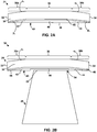
- FIG. 2A is conceptual diagram illustrating an enlarged cross-sectional view of the example blade shroud segment 24 of FIG. 1 including a substrate 30 and a tapered abradable coating layer 40.
- the cross-sectional view of FIG. 2A is taken along the major axis of gas turbine engine 10, extending from the intake of gas turbine engine 10 to the exhaust of gas turbine engine 10, i.e., FIG. 2A is a longitudinal or axial cross-sectional view.
- blade shroud segment 24 is described with respect to a blade shroud of turbine 18 of gas turbine engine 10, in other examples, blade shroud segment 24 may be part of an additional or alternative portion of gas turbine engine 10 (e.g., a high-pressure compressor stage or the like).
- Substrate 30 may include a material suitable for use in a high-temperature environment.
- substrate 30 includes a superalloy including, for example, an alloy based on Ni, Co, Ni/Fe, or the like.
- substrate 30 may also include one or more additives such as titanium (Ti), cobalt (Co), or aluminum (Al), which may improve the mechanical properties of substrate 30 including, for example, toughness, hardness, temperature stability, corrosion resistance, oxidation resistance, or the like.
- substrate 30 may include a ceramic or a ceramic matrix composite (CMC).
- Suitable ceramic materials may include, for example, a silicon-containing ceramic, such as silica (SiO 2 ) and/or silicon carbide (SiC); silicon nitride (Si 3 N 4 ); alumina (Al 2 O 3 ); an aluminosilicate; a transition metal carbide (e.g., WC, Mo 2 C, TiC); a silicide (e.g., MoSi 2 , NbSi 2 , TiSi 2 ); combinations thereof; or the like.
- the ceramic may be substantially homogeneous.
- substrate 30 may include a matrix material and a reinforcement material.
- the matrix material and reinforcement materials may include, for example, any of the ceramics described herein.
- the reinforcement material may be continuous or discontinuous.
- the reinforcement material may include discontinuous whiskers, platelets, fibers, or particulates. Additionally, or alternatively, the reinforcement material may include a continuous monofilament or multifilament two-dimensional or three-dimensional weave, braid, fabric, or the like.
- the CMC includes a SiC matrix material (alone or with residual Si metal) and an SiC reinforcement material.
- first angle ⁇ 1 and second angle ⁇ 2 may be substantially the same. In other examples, first angle ⁇ 1 and second angle ⁇ 2 may be inclined relative to center portion 36 at different angles. In some cases, one or both of first inclined portion 38a or second inclined portion 38b may be angled relative to substrate 30 at a non-constant angle. For instance, first angle ⁇ 1 and/or second angle ⁇ 2 may gradually change along substrate 30. In this way, first and second tapered portions 42 and 44 may not have continuous rates or degrees of taper, but the tapers are still relatively gradual and continuous from center portion 36 to leading edge 32 or trailing edge 34, respectively, in comparison to a substrate including stepped pockets.
- the tape and/or fabric may not have to be bent at such sharp angles, which may help prevent the tape and/or fabric from breaking, cracking, and/or delaminating.
- blade shroud segment 24 optionally includes an intermediate coating 48 between substrate 30 and tapered abradable coating 40.
- intermediate coating 48 may include at least one of a bond coat, an environmental barrier coating (EBC) layer, or a thermal barrier coating (TBC) layer.
- EBC environmental barrier coating
- TBC thermal barrier coating
- a single intermediate coating 48 may perform two or more of these functions.
- an EBC layer may provide environmental protection, thermal protection, and calcia-magnesia-alumina-silicate (CMAS)-resistance to substrate 30.
- blade shroud segment 24 may include a plurality of intermediate coatings, such as at least one bond coat, at least one EBC layer, at least one TBC layer, or combinations thereof.
- Intermediate coating 48 including a bond coat may improve adhesion between substrate 30 and an overlying layer, such as tapered abradable coating layer 40.
- the bond coat may include any suitable material configured to improve adhesion between substrate 30 and tapered abradable coating layer 40.
- intermediate coating 48 may include additional layers between a bond coat and tapered abradable coating layer 40.
- the composition of the bond coat may be selected to increase adhesion between substrate 30 and the layer that is on the bond coat.
- the rare-earth element in the at least one rare-earth oxide, the at least one rare-earth monosilicate, or the at least one rare-earth disilicate may include at least one of Lu, Yb, Tm, Er, Ho, Dy, Tb, Gd, Eu, Sm, Pm, Nd, Pr, Ce, La, Y, or Sc.
- Tapered abradable coating layer 40 may include any suitable material.
- tapered abradable coating layer 40 may be formed from materials that exhibit a hardness that is relatively lower than a hardness of a blade tip of a rotating blade such that the blade tip can abrade tapered abradable coating layer 40 by contact.
- the hardness of tapered abradable coating layer 40 relative to the hardness of the blade tip may be indicative of the abradability of tapered abradable coating layer 40.
- Tapered abradable coating layer 40 may optionally include other elements or compounds to modify a desired characteristic of the coating layer, such as, for example, phase stability, thermal conductivity, or the like.
- Example additive elements or compounds include, for example, rare earth oxides. The inclusion of one or more rare earth oxides, such as ytterbia, gadolinia, and samaria, within a layer of predominately zirconia may help decrease the thermal conductivity of tapered abradable coating layer 40, e.g., compared to a composition including zirconia and yttria.
- First tapered portion 42 may substantially continuously taper in a direction perpendicular to leading edge 32 and/or trailing edge 34 from center portion 36 of substrate 30 (e.g., beginning at blade rub portion 46) toward leading edge 32 of substrate 30.
- second tapered portion 44 may substantially continuously taper in a direction perpendicular to leading edge 32 and/or trailing edge 34 from center portion 36 of substrate 30 (e.g., beginning at blade rub portion 46) toward trailing edge 34 of substrate 30.
- tapered abradable coating layer 40 may have a relatively constant thickness within blade rub region 46 (e.g., across the first width of blade rub portion 46).
- vibration of blades 26, imperfect circumferential alignment of a plurality of blades 26, inconsistent widths of a plurality of blade tips 52, or the like may still enable formation of blade path 54 without an underlying coating layer (e.g., intermediate coating 48) or substrate 30 being contacted and/or abraded by the blade tips.
- a non-linear shape any of first tapered portion 42, second tapered portion 44, first inclined portion 38a, and/or second inclined portion 38b may be easier or less expensive to manufacture or apply as tapered abradable coating layer 40. Additionally, or alternatively, a non-linear shape of any of first tapered portion 42, second tapered portion 44, first inclined portion 38a, and/or second inclined portion 38b may allow for a further reduction in the thermal gradient in comparison to a substantially linear shape.
- blade shroud segment 24 may define a larger segment, or the entirety, of blade shroud.
- blade shroud segment 24 may define a cylindrical surface, and thus, the exterior surface of tapered abradable coating layer 40 may also define a cylindrical exterior surface.
- blade shroud segment 24 or a blade shroud may be non-symmetrical.
- first taper angle ⁇ 1 of first tapered portion 42 may be substantially the same as first angle ⁇ 1 of first inclined portion 38a (e.g., relative to center portion 36) and a second taper angle ⁇ 2 of second tapered portion 44 may be substantially the same as second angle ⁇ 2 of second inclined portion 38b (e.g., relative to center portion 36).
- first taper angle ⁇ 1 may be between about 1° and about 30° and second taper angle ⁇ 2 may be between about 1° and about 30°.
- one or both of first taper angle ⁇ 1 and second taper angle ⁇ 2 may be between about 15° and about 30°.
- tapered abradable coating layer 40 may define a relatively non-curvilinear exterior surface.
- the substrate may have a relatively curvilinear surface (e.g., with no inclined portions) and the tapered abradable coating may have a tapered exterior surface.
- FIG. 3A is conceptual diagram illustrating an enlarged cross-sectional view of another example blade shroud segment 60 including a substrate 62 and a tapered abradable coating layer 70.
- FIG. 3B is conceptual diagram illustrating an enlarged cross-sectional view of a system 80 including the example blade shroud segment 60 of FIG. 3A and a blade 26.
- tapered abradable coating layer 70 defines a tapered exterior surface such that tapered abradable coating layer 70 includes a first tapered portion 72 and a second tapered portion 74 rather than a relatively constant surface from leading edge 64 to trailing edge 66.
- tapered abradable coating layer 70 includes first tapered portion 72 that substantially continuously tapers in a direction perpendicular to leading edge 64 or trailing edge 66 from a center portion of the substrate 62 toward leading edge 64 of substrate 62, and includes second tapered portion 74 that substantially continuously tapers in a direction perpendicular to leading edge 64 or trailing edge 66 from the center portion of substrate 62 toward trailing edge 66.
- first tapered portion 72 may define a first taper angle ⁇ 1 between about 1° and about 30°, or between about 15° and about 30°
- second tapered portion 74 may define a second taper angle ⁇ 2 between about 1° and about 30°, or between about 15° and about 30°.
- blade shroud segment 60 may also have a reduced thermal gradient in comparison to a constant thickness abradable coating, as first and second tapered portions 72, 74 may define a minimum thickness, such as a minimum thickness to protect substrate 62 from a severe operating environment, and blade rub portion 76 may define a thickness sufficient to be abraded by blade tip 52 without intermediate coating 48 and/or substrate 62 from be contacted by blade tip 52.
- first tapered portion 72 may have a minimum thickness of greater than 0 mm, such as, at least about 0.075 mm (about 0.003 inches)
- second tapered portion 74 may have a minimum thickness of greater than 0 mm, such as at least about 0.075 mm (about 0.003 inches)
- blade rub portion 76 may have a thickness between about 0.25 mm (about 0.01 inches) and about 3 mm (about 0.12 inches).
- blade shroud segment 60 does not include steps in substrate 62.
- blade shroud segment 60 including tapered abradable coating layer 70 may experience reduced thermal stress and/or better distribute stress across blade shroud segment 60, may be more aerodynamic, and/or tapered abradable coating layer 70 may be less likely to spall and/or delaminate in comparison to a constant thickness abradable coating or a substrate including an abradable coating in a pocket of the substrate.
- a shroud or blade track may include an abradable coating layer that tapers from the center portion of the abradable coating layer to an intersegment edge.
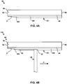
- FIG. 4A is a conceptual diagram illustrating an enlarged cross-sectional view of another example blade shroud segment 90 including a substrate 92 and a tapered abradable coating layer 102.
- FIG. 4B is conceptual diagram illustrating an enlarged cross-sectional view of a system 110 including the example blade track 90 of FIG. 4A and a blade 26. The cross-sectional views of FIGS.
- Blade shroud segment 90 includes a substrate 92 and tapered abradable coating 102.
- blade shroud segment 90 may also include intermediate coating 48.
- Substrate 92, tapered abradable coating layer 102, and intermediate coating 48 may be the same or substantially similar to the substrates, tapered abradable coating layers, and intermediate coatings described herein with respect to FIGS. 2A-3B , aside from the differences described herein.
- substrate 92, tapered abradable coating layer 102, and intermediate coating 48 may be formed from the same or substantially the same materials and/or using the same or substantially the same techniques as described above.
- FIGS. 4A and 4B may illustrate cross-sectional views of blade shroud segment 24 and system 50 of FIGS. 2A and 2B or blade shroud segment 60 and system 80 of FIGS. 3A and 3B .
- Substrate 92 defines an intersegment edge 94 and an opposing edge 96.
- Intersegment edge 94 may be adjacent to a segment of another blade shroud of a gas turbine engine, e.g., in the direction counter to the rotational direction of the blade (see FIG. 4B ).
- a gas turbine engine may include a plurality of blade shroud segments in a circumferential arrangement to form the blade shrouds that surround a plurality of blades.
- opposing edge 96 may also be adjacent to a segment of another blade shroud (e.g., a different segment than intersegment edge 94 is adjacent to in the rotational direction of the blade; see FIG. 4B ). That is, upon normal circumferential rotation of blade 26, blade tip 52 may be configured to move in the direction of arrow A as illustrated in FIG. 4B .
- tapered abradable coating layer 102 including tapered portion 104 that substantially continuously tapers from the center portion of substrate 92 to intersegment edge 94 may improve a tip rub capability of tapered abradable coating layer 102.
- tapered portion 104 results in blade tip 52 gradually engaging with tapered abradable coating layer 102 due to tapered portion 104 at intersegment edge 94.
- tapered portion 104 may define a minimum thickness of greater than 0 mm (e.g., at least about 0.075 mm (about 0.003 inches)) and non-tapered portion 106 may define a thickness between about 0.25 mm (about 0.01 inches) and about 3 mm (about 0.12 inches). In other examples, tapered portion 104 and/or non-tapered portion 106 may define alternative thicknesses.
- a substrate may include a tapered abradable coating layer that includes three or more tapered portions.
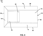
- a tapered abradable coating layer may taper from a center portion of a substrate toward a leading edge of the substrate, from the center portion of the substrate toward a trailing edge of the substrate, and from the center portion of the substrate toward an intersegment edge of the substrate, as shown in FIG. 5 .
- FIG. 5 is a conceptual diagram illustrating a top-down view of an example system 120 including a tapered abradable coating layer 122 including three tapered portions.
- tapered abradable coating layer 122 may be a combination of tapered abradable coating layer 70 of FIGS. 3A and 3B and tapered abradable coating layer 102 of FIGS. 4A and 4B .
- tapered abradable coating layer 122 includes first tapered portion 72 that substantially continuously tapers from a center portion of a substrate (not shown) to leading edge 64, second tapered portion 74 that substantially continuously tapers from the center portion to trailing edge 66, and a third tapered portion 104 that substantially continuously tapers from the center portion to intersegment edge 94.
- the center portion of the substrate may extend between leading edge 64, trailing edge 66, intersegment edge 94, and opposing edge 96.
- tapered abradable coating layer 122 may include four or more tapered portions.
- tapered abradable coating layer 122 may include a fourth tapered portion that substantially continuously tapers from the center portion of the substrate to opposing edge 96 of the substrate.
- tapered abradable coating layer 122 may be a combination of tapered abradable coating layer 40 of FIGS. 2A and 2B and tapered abradable coating layer 102 of FIGS. 4A and 4B , or any other tapered abradable coating layers as described herein, instead of a combination of tapered abradable coating layer 70 of FIGS. 3A and 3B and tapered abradable coating layer 102 of FIGS. 4A and 4B .
- the technique of FIG. 6 may include obtaining substrate 62 with a desired geometry (130). For example, in some cases, a substrate 62 with a substantially curvilinear surface from leading edge 64 to trailing edge 66 may be obtained. In other examples, other surface shapes such as planar, conical, a portion of a conical shape, or the like may be obtained. In yet other cases, a substrate including one or more inclined portions (e.g., first and/or second inclined portions 38a, 38b as in the example of FIG. 2A ) may be obtained. In some examples, obtaining substrate 62 with a desired geometry may include manufacturing substrate 62 with the desired geometry. For example, substrate 62 may manufactured to define a substantially curvilinear surface from leading edge 64 to trailing edge 66. Similarly, a substrate may be manufactured to form one or more inclined portions. In some such examples, the substrate may be manufactured to the desired end-shape. In other examples, the substrate may be machined to form the one or more inclined portions in the substrate.
- the technique of FIG. 6 optionally includes applying intermediate coating 48 on substrate 62 (132).
- applying intermediate coating 48 on substrate 62 includes applying at least one of a bond coat, an EBC layer, a TBC layer, or a CMAS-resistant layer on substrate 62.
- Intermediate coating 48 may be applied on substrate 62 using any suitable technique.
- intermediate coating 48 may be applied on substrate 62 via thermal spraying, e.g., air plasma spraying, HVOF spraying, low vapor plasma spraying, suspension plasma spraying; PVD , e.g., EB-PVD, DVD, or cathodic arc deposition; CVD; slurry process deposition; sol-gel process deposition; electrophoretic deposition; or the like.
- intermediate coating 48 may be applied on substrate 62 using an additional or alternative technique.
- tapered abradable coating layer 70 on substrate 62 (134). Similar to intermediate coating 48, tapered abradable coating layer 70 may be applied on substrate 62 using any suitable technique, such as, for example, thermal spraying, e.g., air plasma spraying, HVOF spraying, low vapor plasma spraying, suspension plasma spraying; PVD, e.g., EB-PVD, DVD, or cathodic arc deposition; CVD; slurry process deposition; sol-gel process deposition; electrophoretic deposition; or the like.
- thermal spraying e.g., air plasma spraying, HVOF spraying, low vapor plasma spraying, suspension plasma spraying
- PVD e.g., EB-PVD, DVD, or cathodic arc deposition
- CVD slurry process deposition
- sol-gel process deposition sol-gel process deposition
- electrophoretic deposition or the like.
- the geometry of substrate 62, a target thickness of blade rub portion 76, a minimum thickness of first tapered portion 72 and/or second tapered portion 74, third and/or fourth taper angles ⁇ 3 , ⁇ 4 , or the like may be considered to apply tapered abradable coating layer 70 on substrate 62.
- a thermal spray technique e.g., a number of coating passes, a velocity of a coating device, or the like
- FIG. 7 is a flow diagram illustrating an example technique of applying a tapered abradable layer on a substrate.
- the technique of FIG. 7 will be described with respect to blade shroud segment 60 of FIG. 3A .
- the technique of FIG. 7 may be used to form articles other than blade shroud segment 60 of FIG. 3A , such as, for example, blade shroud segment 24 of FIG. 2A .
- additional or alternative techniques may be used to form the tapered abradable coating layers as described herein.
- the technique illustrated in FIG. 7 includes receiving, by a computing device, a geometry of substrate 62 (140).
- the computing device may include a desktop computer, a laptop computer, a tablet computer, a workstation, a server, a mainframe, a cloud computing system, a robot controller, or the like.
- the computing device may be configured to control operation of a coating system, including, for example, a stage and a mount for securing an article to be coated, a measuring device to measure a surface geometry of the article, and/or a coating device for applying a coating.
- the computing device may be communicatively coupled to the stage, the mount, the measuring device, and/or the coating device using respective wired and/or wireless communication connections, e.g., a network link, such as Ethernet or other network connections, USB, IEEE 1394, or the like.
- a network link such as Ethernet or other network connections, USB, IEEE 1394, or the like.
- the technique of FIG. 7 includes determining, by the computing device, a target thickness of at least a portion of tapered abradable coating layer 70 to be applied on substrate 62 (142).
- the computing device may determine one or more of a target thickness of blade rub portion 76, a minimum thickness of first tapered portion 72, or a minimum thickness of second tapered portion 74.
- the target thickness of blade rub portion 76 may include a thickness so that blade tip 52 does not contact or abrade intermediate coating 48 and/or substrate 62 during rotation of blade 26.
- the computing device may determine a velocity of the coating device relative to substrate 62 for each respective location of the surface of substrate 62 (e.g., a respective velocity for each respective subroutine of the coating device).
- the technique of FIG. 7 may include determining, by the computing device, a number of passes of the coating device with respect to each location of the surface of substrate 62, a velocity of the coating device with respect to each location of the surface of substrate 62, or both, in order to determine a coating program for applying tapered abradable coating layer 70 to achieve the target thickness of at least the portion, such as blade rub portion 76.
- a coating pass reduction width may be selected.
- additional parameters may be used to select the coating pass reduction width.
- a width of blade rub portion 76, first tapered portion 72, and/or second tapered portion 74, a minimum thickness of first and/or second tapered portion 72, 74, or the like may be used to select the coating pass reduction width.
- the coating pass reduction width may be about 5 mm.
- the coating pass reduction width may be a different width. For instance, the coating pass reduction width may be determined based on the length of first tapered portion 72 and/or second tapered portion 74.
- the coating program may include applying a first coating pass of tapered abradable coating layer 70 from an initial position on substrate 62 to a terminal position on substrate 62.
- the initial position may include leading edge 64 and the terminal position may include trailing edge 66.
- a second coating pass may be applied on substrate 62 from a subsequent initial position on substrate 62 to a subsequent terminal position on substrate 62.
- the subsequent initial position may be a distance of the coating pass reduction width from the previous initial position (e.g., the initial position) in a direction toward the terminal position.
- the subsequent terminal position may be a distance of the coating pass reduction width from the previous terminal position (e.g., the terminal position) in a direction toward the initial position.
- Additional coating passes may be applied on substrate 62 in a similar manner until the target thickness of the portion of tapered abradable coating layer 70 is achieved. For example, each subsequent initial position of each coating pass may be about the coating pass reduction width closer to the terminal position in comparison to a previous initial position of a previous coating pass. Similarly, each subsequent terminal position of each coating pass may be about the coating pass reduction width closer to the initial position in comparison to a previous terminal position of a previous coating pass. In some examples, one or more additional coating passes may be applied on substrate 62 once the target thickness has been achieved. For example, a plurality of coating passes having a width of blade rub portion 76 may be applied on substrate 62 such that blade rub portion 76 defines a substantially constant thickness portion of tapered abradable coating layer 70.
- only one of the subsequent initial positions or subsequent terminal positions may be adjusted by the coating pass reduction width.
- tapered abradable coating layer 70 only includes one tapered portion (e.g., tapered abradable coating layer 102 of FIGS. 4A and 4B )
- only one tapered portion may need to be formed using a coating program including a coating pass reduction technique.
- each subsequent coating pass may not be adjusted by the coating pass width.
- the coating pass width may be adjusted by the coating pass reduction width every 3, 5, 8, 10, or 20 coating passes.
- the coating program may not adjust the coating pass width at the same interval, by the same coating pass reduction width, or the like over the entire coating program (e.g., over a plurality of coating passes to form tapered abradable coating layer 70).
- the technique of FIG. 7 further includes applying tapered abradable coating layer 70 on substrate 62 (146).
- applying tapered abradable coating layer 70 on substrate 62 may include controlling the coating device to apply tapered abradable coating layer 70 on substrate using the determined number of passes and/or velocity of the coating device to achieve the target thickness.
- tapered abradable coating layer 70 may be applied on substrate 62 using a coating program, such as, for example, a coating program including the coating pass reduction technique as described herein.
- the subject-matter of the disclosure may also relate, among others, to the following aspects:
Landscapes
- Engineering & Computer Science (AREA)
- Mechanical Engineering (AREA)
- General Engineering & Computer Science (AREA)
- Turbine Rotor Nozzle Sealing (AREA)
- Structures Of Non-Positive Displacement Pumps (AREA)
- Coating By Spraying Or Casting (AREA)
Applications Claiming Priority (1)
| Application Number | Priority Date | Filing Date | Title |
|---|---|---|---|
| US15/986,570 US10808565B2 (en) | 2018-05-22 | 2018-05-22 | Tapered abradable coatings |
Publications (2)
| Publication Number | Publication Date |
|---|---|
| EP3575559A1 true EP3575559A1 (fr) | 2019-12-04 |
| EP3575559B1 EP3575559B1 (fr) | 2021-02-03 |
Family
ID=66217744
Family Applications (1)
| Application Number | Title | Priority Date | Filing Date |
|---|---|---|---|
| EP19169441.3A Active EP3575559B1 (fr) | 2018-05-22 | 2019-04-16 | Revêtements abradables coniques |
Country Status (4)
| Country | Link |
|---|---|
| US (1) | US10808565B2 (fr) |
| EP (1) | EP3575559B1 (fr) |
| JP (1) | JP7269768B2 (fr) |
| CA (1) | CA3037388A1 (fr) |
Cited By (1)
| Publication number | Priority date | Publication date | Assignee | Title |
|---|---|---|---|---|
| FR3100048A1 (fr) * | 2019-08-23 | 2021-02-26 | Safran Ceramics | Anneau de turbine en CMC avec revêtement de protection à épaisseur variable et procédé de fabrication d’un tel anneau |
Families Citing this family (14)
| Publication number | Priority date | Publication date | Assignee | Title |
|---|---|---|---|---|
| US10900371B2 (en) * | 2017-07-27 | 2021-01-26 | Rolls-Royce North American Technologies, Inc. | Abradable coatings for high-performance systems |
| US10858950B2 (en) | 2017-07-27 | 2020-12-08 | Rolls-Royce North America Technologies, Inc. | Multilayer abradable coatings for high-performance systems |
| US10808565B2 (en) | 2018-05-22 | 2020-10-20 | Rolls-Royce Plc | Tapered abradable coatings |
| US11255209B2 (en) * | 2019-08-29 | 2022-02-22 | Raytheon Technologies Corporation | CMC BOAS arrangement |
| EP3838870A1 (fr) | 2019-12-19 | 2021-06-23 | Rolls-Royce Corporation | Revêtements abradables résistants aux cmas |
| US11566531B2 (en) | 2020-10-07 | 2023-01-31 | Rolls-Royce Corporation | CMAS-resistant abradable coatings |
| AU2022238864B2 (en) * | 2021-03-17 | 2024-08-22 | Oerlikon Metco (Us) Inc. | Chemically complex ceramic abradable sealant materials |
| US11692490B2 (en) * | 2021-05-26 | 2023-07-04 | Doosan Heavy Industries & Construction Co., Ltd. | Gas turbine inner shroud with abradable surface feature |
| US11761341B2 (en) | 2021-07-27 | 2023-09-19 | Honeywell International Inc. | Protective coating systems for gas turbine engine applications and methods for fabricating the same |
| US11732598B2 (en) | 2021-12-17 | 2023-08-22 | Rolls-Royce Corporation | Ceramic matrix composite turbine shroud shaped for minimizing abradable coating layer |
| JP2023133660A (ja) * | 2022-03-14 | 2023-09-27 | 三菱重工業株式会社 | 高温部品、回転機械及び高温部品の製造方法 |
| US12503953B2 (en) * | 2024-02-13 | 2025-12-23 | Rtx Corporation | Ceramic matrix composite component with coating |
| US12291971B1 (en) * | 2024-02-13 | 2025-05-06 | Rtx Corporation | Blade outer air seal with graded coating |
| US12553358B2 (en) * | 2024-04-05 | 2026-02-17 | Rtx Corporation | Porosity variation of abradable based on hardness of material |
Citations (3)
| Publication number | Priority date | Publication date | Assignee | Title |
|---|---|---|---|---|
| US20160047264A1 (en) * | 2011-07-15 | 2016-02-18 | United Technologies Corporation | Blade outer air seal having partial coating |
| US20170276007A1 (en) * | 2016-03-23 | 2017-09-28 | United Technologies Corporation | Outer Airseal Insulated Rub Strip |
| EP3239475A1 (fr) * | 2016-04-25 | 2017-11-01 | United Technologies Corporation | Bande de frottement abradable de joint externe |
Family Cites Families (65)
| Publication number | Priority date | Publication date | Assignee | Title |
|---|---|---|---|---|
| US3519282A (en) * | 1966-03-11 | 1970-07-07 | Gen Electric | Abradable material seal |
| US3719365A (en) * | 1971-10-18 | 1973-03-06 | Gen Motors Corp | Seal structure |
| US4218066A (en) * | 1976-03-23 | 1980-08-19 | United Technologies Corporation | Rotary seal |
| US4269903A (en) | 1979-09-06 | 1981-05-26 | General Motors Corporation | Abradable ceramic seal and method of making same |
| US4337016A (en) * | 1979-12-13 | 1982-06-29 | United Technologies Corporation | Dual wall seal means |
| US4503130A (en) | 1981-12-14 | 1985-03-05 | United Technologies Corporation | Prestressed ceramic coatings |
| US4422648A (en) * | 1982-06-17 | 1983-12-27 | United Technologies Corporation | Ceramic faced outer air seal for gas turbine engines |
| US4744725A (en) * | 1984-06-25 | 1988-05-17 | United Technologies Corporation | Abrasive surfaced article for high temperature service |
| US4639388A (en) * | 1985-02-12 | 1987-01-27 | Chromalloy American Corporation | Ceramic-metal composites |
| JP2742471B2 (ja) * | 1989-11-27 | 1998-04-22 | ユナイテッド・テクノロジ―ズ・コーポレイション | 液体ジェットによるコーティング等除去方法及びそれにより得られる物品 |
| US5375973A (en) * | 1992-12-23 | 1994-12-27 | United Technologies Corporation | Turbine blade outer air seal with optimized cooling |
| US5439348A (en) * | 1994-03-30 | 1995-08-08 | United Technologies Corporation | Turbine shroud segment including a coating layer having varying thickness |
| US5662757A (en) * | 1994-10-17 | 1997-09-02 | General Electric Company | Method of removing an abradable shroud assembly for turbomachinery |
| US5951892A (en) * | 1996-12-10 | 1999-09-14 | Chromalloy Gas Turbine Corporation | Method of making an abradable seal by laser cutting |
| SG72959A1 (en) * | 1998-06-18 | 2000-05-23 | United Technologies Corp | Article having durable ceramic coating with localized abradable portion |
| US6670046B1 (en) * | 2000-08-31 | 2003-12-30 | Siemens Westinghouse Power Corporation | Thermal barrier coating system for turbine components |
| DE10121019A1 (de) * | 2001-04-28 | 2002-10-31 | Alstom Switzerland Ltd | Gasturbinendichtung |
| US6660405B2 (en) * | 2001-05-24 | 2003-12-09 | General Electric Co. | High temperature abradable coating for turbine shrouds without bucket tipping |
| US20030138658A1 (en) * | 2002-01-22 | 2003-07-24 | Taylor Thomas Alan | Multilayer thermal barrier coating |
| US20040086635A1 (en) * | 2002-10-30 | 2004-05-06 | Grossklaus Warren Davis | Method of repairing a stationary shroud of a gas turbine engine using laser cladding |
| US6887529B2 (en) * | 2003-04-02 | 2005-05-03 | General Electric Company | Method of applying environmental and bond coatings to turbine flowpath parts |
| DE10353810A1 (de) * | 2003-11-17 | 2005-06-23 | Rolls-Royce Deutschland Ltd & Co Kg | Innendeckband für die Statorschaufeln des Verdichters einer Gasturbine |
| US7726936B2 (en) * | 2006-07-25 | 2010-06-01 | Siemens Energy, Inc. | Turbine engine ring seal |
| US7819625B2 (en) * | 2007-05-07 | 2010-10-26 | Siemens Energy, Inc. | Abradable CMC stacked laminate ring segment for a gas turbine |
| US8100640B2 (en) * | 2007-10-25 | 2012-01-24 | United Technologies Corporation | Blade outer air seal with improved thermomechanical fatigue life |
| US8046915B2 (en) * | 2007-12-12 | 2011-11-01 | General Electric Company | Methods for making composite containment casings |
| US20090324930A1 (en) | 2008-06-25 | 2009-12-31 | United Technologies Corporation | Protective coatings for silicon based substrates with improved adhesion |
| US20100030365A1 (en) * | 2008-07-30 | 2010-02-04 | Pratt & Whitney | Combined matching and inspection process in machining of fan case rub strips |
| US8470460B2 (en) * | 2008-11-25 | 2013-06-25 | Rolls-Royce Corporation | Multilayer thermal barrier coatings |
| US8124252B2 (en) * | 2008-11-25 | 2012-02-28 | Rolls-Royce Corporation | Abradable layer including a rare earth silicate |
| GB0822416D0 (en) * | 2008-12-10 | 2009-01-14 | Rolls Royce Plc | A seal and a method of manufacturing a seal |
| US8309197B2 (en) * | 2008-12-17 | 2012-11-13 | Teledyne Scientific & Imaging, Llc | Integral abradable seals |
| US8343589B2 (en) | 2008-12-19 | 2013-01-01 | General Electric Company | Methods for making environmental barrier coatings and ceramic components having CMAS mitigation capability |
| US8658255B2 (en) | 2008-12-19 | 2014-02-25 | General Electric Company | Methods for making environmental barrier coatings and ceramic components having CMAS mitigation capability |
| US8172519B2 (en) | 2009-05-06 | 2012-05-08 | General Electric Company | Abradable seals |
| US20110033630A1 (en) * | 2009-08-05 | 2011-02-10 | Rolls-Royce Corporation | Techniques for depositing coating on ceramic substrate |
| EP2524069B1 (fr) | 2010-01-11 | 2018-03-07 | Rolls-Royce Corporation | Caractéristiques d'atténuation des contraintes méchaniques ou thermiques d'un revêtement de barrière environnementale |
| US20110219775A1 (en) | 2010-03-12 | 2011-09-15 | Jarmon David C | High tolerance controlled surface for ceramic matrix composite component |
| US20140199163A1 (en) * | 2011-03-09 | 2014-07-17 | Rolls-Royce Corporation- | Abradable layer including a low thermal conductivity composition |
| US8777562B2 (en) * | 2011-09-27 | 2014-07-15 | United Techologies Corporation | Blade air seal with integral barrier |
| US20130236293A1 (en) * | 2012-03-09 | 2013-09-12 | General Electric Company | Systems and methods for an improved stator |
| US9598973B2 (en) * | 2012-11-28 | 2017-03-21 | General Electric Company | Seal systems for use in turbomachines and methods of fabricating the same |
| WO2014158286A1 (fr) | 2013-03-12 | 2014-10-02 | Thomas David J | Ensemble de sillages de pales de turbine |
| US9284843B2 (en) * | 2013-03-13 | 2016-03-15 | The Boeing Company | Blade safety mechanism for open rotor engine system |
| US9458726B2 (en) * | 2013-03-13 | 2016-10-04 | Rolls-Royce Corporation | Dovetail retention system for blade tracks |
| FR3007064B1 (fr) * | 2013-06-13 | 2018-06-29 | Composite Industrie | Secteur de joint annulaire abradable pour turbomachine et procede de fabrication d'une telle piece |
| US9751260B2 (en) * | 2013-07-24 | 2017-09-05 | The Boeing Company | Additive-manufacturing systems, apparatuses and methods |
| US8939706B1 (en) * | 2014-02-25 | 2015-01-27 | Siemens Energy, Inc. | Turbine abradable layer with progressive wear zone having a frangible or pixelated nib surface |
| US8939707B1 (en) * | 2014-02-25 | 2015-01-27 | Siemens Energy, Inc. | Turbine abradable layer with progressive wear zone terraced ridges |
| US20150239010A1 (en) * | 2014-02-26 | 2015-08-27 | Pratt & Whitney Canada Corp. | Method of forming an abradable coating for a gas turbine engine |
| KR102318300B1 (ko) * | 2014-05-15 | 2021-10-29 | 누보 피그노네 에스알엘 | 터보기계의 구성요소의 제조 방법, 터보기계의 구성요소 및 터보기계 |
| GB201410264D0 (en) * | 2014-06-10 | 2014-07-23 | Rolls Royce Plc | An assembly |
| US10421692B2 (en) * | 2014-06-30 | 2019-09-24 | General Electric Company | Thermal and environmental barrier coating compositions and methods of deposition |
| PL3023511T3 (pl) * | 2014-11-24 | 2021-12-20 | Safran Aero Boosters Sa | Kompozycja i ścieralna uszczelka obudowy sprężarki osiowej maszyny wirowej |
| US20160305319A1 (en) * | 2015-04-17 | 2016-10-20 | General Electric Company | Variable coating porosity to influence shroud and rotor durability |
| US20170089213A1 (en) * | 2015-09-28 | 2017-03-30 | United Technologies Corporation | Duct with additive manufactured seal |
| US9644489B1 (en) * | 2015-12-16 | 2017-05-09 | Siemens Energy, Inc. | Additive manufacturing of abradable mesh structure on ring segment surface |
| US10138749B2 (en) * | 2016-03-16 | 2018-11-27 | United Technologies Corporation | Seal anti-rotation feature |
| US10267174B2 (en) * | 2016-04-28 | 2019-04-23 | United Technologies Corporation | Outer airseal abradable rub strip |
| US10196918B2 (en) | 2016-06-07 | 2019-02-05 | United Technologies Corporation | Blade outer air seal made of ceramic matrix composite |
| US10808539B2 (en) * | 2016-07-25 | 2020-10-20 | Raytheon Technologies Corporation | Rotor blade for a gas turbine engine |
| US10546078B2 (en) * | 2017-01-13 | 2020-01-28 | General Electric Company | Turbofan case for controlling blade deflection |
| US10632650B2 (en) | 2017-04-07 | 2020-04-28 | General Electric Company | Methods and assemblies for forming features in composite components |
| US10737444B2 (en) | 2017-04-07 | 2020-08-11 | General Electric Company | Methods and assemblies for forming features in composite components |
| US10808565B2 (en) | 2018-05-22 | 2020-10-20 | Rolls-Royce Plc | Tapered abradable coatings |
-
2018
- 2018-05-22 US US15/986,570 patent/US10808565B2/en active Active
-
2019
- 2019-03-20 CA CA3037388A patent/CA3037388A1/fr not_active Abandoned
- 2019-03-25 JP JP2019056221A patent/JP7269768B2/ja active Active
- 2019-04-16 EP EP19169441.3A patent/EP3575559B1/fr active Active
Patent Citations (3)
| Publication number | Priority date | Publication date | Assignee | Title |
|---|---|---|---|---|
| US20160047264A1 (en) * | 2011-07-15 | 2016-02-18 | United Technologies Corporation | Blade outer air seal having partial coating |
| US20170276007A1 (en) * | 2016-03-23 | 2017-09-28 | United Technologies Corporation | Outer Airseal Insulated Rub Strip |
| EP3239475A1 (fr) * | 2016-04-25 | 2017-11-01 | United Technologies Corporation | Bande de frottement abradable de joint externe |
Cited By (1)
| Publication number | Priority date | Publication date | Assignee | Title |
|---|---|---|---|---|
| FR3100048A1 (fr) * | 2019-08-23 | 2021-02-26 | Safran Ceramics | Anneau de turbine en CMC avec revêtement de protection à épaisseur variable et procédé de fabrication d’un tel anneau |
Also Published As
| Publication number | Publication date |
|---|---|
| US10808565B2 (en) | 2020-10-20 |
| EP3575559B1 (fr) | 2021-02-03 |
| JP2019203497A (ja) | 2019-11-28 |
| CA3037388A1 (fr) | 2019-11-22 |
| US20190360351A1 (en) | 2019-11-28 |
| JP7269768B2 (ja) | 2023-05-09 |
Similar Documents
| Publication | Publication Date | Title |
|---|---|---|
| EP3575559B1 (fr) | Revêtements abradables coniques | |
| US11506073B2 (en) | Multilayer abradable coatings for high-performance systems | |
| US11313243B2 (en) | Non-continuous abradable coatings | |
| EP2521802B1 (fr) | Systeme de revetement pour reduction des jeux dans des machines tournantes | |
| EP2925971B1 (fr) | Dispositifs d'étanchéité destinés à être utilisés dans des turbomachines et leurs procédés de fabrication | |
| US11566531B2 (en) | CMAS-resistant abradable coatings | |
| EP1908856B1 (fr) | Revêtements abradables segmentés et processus pour les appliquer | |
| US10900371B2 (en) | Abradable coatings for high-performance systems | |
| CN105443165B (zh) | 可磨耗密封件及用于形成可磨耗密封件的方法 | |
| EP2192098A2 (fr) | Couche abradable incluant un silicate de terre rare | |
| EP3440318B1 (fr) | Géométries de joint pour limiter les fuites dans des turbines à gaz et procédés de formation | |
| KR20040077771A (ko) | 다층식 열 배리어 코팅 | |
| US20190093499A1 (en) | Non-continuous abradable coatings | |
| EP3613869B1 (fr) | Revêtement abradable pour composants dans des systèmes mécaniques à haute température | |
| JP2018184662A (ja) | 高温用の物品 |
Legal Events
| Date | Code | Title | Description |
|---|---|---|---|
| PUAI | Public reference made under article 153(3) epc to a published international application that has entered the european phase |
Free format text: ORIGINAL CODE: 0009012 |
|
| STAA | Information on the status of an ep patent application or granted ep patent |
Free format text: STATUS: THE APPLICATION HAS BEEN PUBLISHED |
|
| AK | Designated contracting states |
Kind code of ref document: A1 Designated state(s): AL AT BE BG CH CY CZ DE DK EE ES FI FR GB GR HR HU IE IS IT LI LT LU LV MC MK MT NL NO PL PT RO RS SE SI SK SM TR |
|
| AX | Request for extension of the european patent |
Extension state: BA ME |
|
| RAP1 | Party data changed (applicant data changed or rights of an application transferred) |
Owner name: ROLLS-ROYCE CORPORATION Owner name: ROLLS-ROYCE PLC |
|
| STAA | Information on the status of an ep patent application or granted ep patent |
Free format text: STATUS: REQUEST FOR EXAMINATION WAS MADE |
|
| 17P | Request for examination filed |
Effective date: 20200518 |
|
| RBV | Designated contracting states (corrected) |
Designated state(s): AL AT BE BG CH CY CZ DE DK EE ES FI FR GB GR HR HU IE IS IT LI LT LU LV MC MK MT NL NO PL PT RO RS SE SI SK SM TR |
|
| GRAP | Despatch of communication of intention to grant a patent |
Free format text: ORIGINAL CODE: EPIDOSNIGR1 |
|
| STAA | Information on the status of an ep patent application or granted ep patent |
Free format text: STATUS: GRANT OF PATENT IS INTENDED |
|
| INTG | Intention to grant announced |
Effective date: 20201126 |
|
| GRAS | Grant fee paid |
Free format text: ORIGINAL CODE: EPIDOSNIGR3 |
|
| GRAA | (expected) grant |
Free format text: ORIGINAL CODE: 0009210 |
|
| STAA | Information on the status of an ep patent application or granted ep patent |
Free format text: STATUS: THE PATENT HAS BEEN GRANTED |
|
| AK | Designated contracting states |
Kind code of ref document: B1 Designated state(s): AL AT BE BG CH CY CZ DE DK EE ES FI FR GB GR HR HU IE IS IT LI LT LU LV MC MK MT NL NO PL PT RO RS SE SI SK SM TR |
|
| REG | Reference to a national code |
Ref country code: GB Ref legal event code: FG4D |
|
| REG | Reference to a national code |
Ref country code: CH Ref legal event code: EP Ref country code: AT Ref legal event code: REF Ref document number: 1359742 Country of ref document: AT Kind code of ref document: T Effective date: 20210215 |
|
| REG | Reference to a national code |
Ref country code: DE Ref legal event code: R096 Ref document number: 602019002416 Country of ref document: DE |
|
| REG | Reference to a national code |
Ref country code: IE Ref legal event code: FG4D |
|
| REG | Reference to a national code |
Ref country code: NL Ref legal event code: MP Effective date: 20210203 |
|
| REG | Reference to a national code |
Ref country code: LT Ref legal event code: MG9D |
|
| REG | Reference to a national code |
Ref country code: AT Ref legal event code: MK05 Ref document number: 1359742 Country of ref document: AT Kind code of ref document: T Effective date: 20210203 |
|
| PG25 | Lapsed in a contracting state [announced via postgrant information from national office to epo] |
Ref country code: BG Free format text: LAPSE BECAUSE OF FAILURE TO SUBMIT A TRANSLATION OF THE DESCRIPTION OR TO PAY THE FEE WITHIN THE PRESCRIBED TIME-LIMIT Effective date: 20210503 Ref country code: HR Free format text: LAPSE BECAUSE OF FAILURE TO SUBMIT A TRANSLATION OF THE DESCRIPTION OR TO PAY THE FEE WITHIN THE PRESCRIBED TIME-LIMIT Effective date: 20210203 Ref country code: FI Free format text: LAPSE BECAUSE OF FAILURE TO SUBMIT A TRANSLATION OF THE DESCRIPTION OR TO PAY THE FEE WITHIN THE PRESCRIBED TIME-LIMIT Effective date: 20210203 Ref country code: GR Free format text: LAPSE BECAUSE OF FAILURE TO SUBMIT A TRANSLATION OF THE DESCRIPTION OR TO PAY THE FEE WITHIN THE PRESCRIBED TIME-LIMIT Effective date: 20210504 Ref country code: PT Free format text: LAPSE BECAUSE OF FAILURE TO SUBMIT A TRANSLATION OF THE DESCRIPTION OR TO PAY THE FEE WITHIN THE PRESCRIBED TIME-LIMIT Effective date: 20210604 Ref country code: NO Free format text: LAPSE BECAUSE OF FAILURE TO SUBMIT A TRANSLATION OF THE DESCRIPTION OR TO PAY THE FEE WITHIN THE PRESCRIBED TIME-LIMIT Effective date: 20210503 Ref country code: LT Free format text: LAPSE BECAUSE OF FAILURE TO SUBMIT A TRANSLATION OF THE DESCRIPTION OR TO PAY THE FEE WITHIN THE PRESCRIBED TIME-LIMIT Effective date: 20210203 |
|
| PG25 | Lapsed in a contracting state [announced via postgrant information from national office to epo] |
Ref country code: PL Free format text: LAPSE BECAUSE OF FAILURE TO SUBMIT A TRANSLATION OF THE DESCRIPTION OR TO PAY THE FEE WITHIN THE PRESCRIBED TIME-LIMIT Effective date: 20210203 Ref country code: RS Free format text: LAPSE BECAUSE OF FAILURE TO SUBMIT A TRANSLATION OF THE DESCRIPTION OR TO PAY THE FEE WITHIN THE PRESCRIBED TIME-LIMIT Effective date: 20210203 Ref country code: LV Free format text: LAPSE BECAUSE OF FAILURE TO SUBMIT A TRANSLATION OF THE DESCRIPTION OR TO PAY THE FEE WITHIN THE PRESCRIBED TIME-LIMIT Effective date: 20210203 Ref country code: NL Free format text: LAPSE BECAUSE OF FAILURE TO SUBMIT A TRANSLATION OF THE DESCRIPTION OR TO PAY THE FEE WITHIN THE PRESCRIBED TIME-LIMIT Effective date: 20210203 Ref country code: AT Free format text: LAPSE BECAUSE OF FAILURE TO SUBMIT A TRANSLATION OF THE DESCRIPTION OR TO PAY THE FEE WITHIN THE PRESCRIBED TIME-LIMIT Effective date: 20210203 Ref country code: SE Free format text: LAPSE BECAUSE OF FAILURE TO SUBMIT A TRANSLATION OF THE DESCRIPTION OR TO PAY THE FEE WITHIN THE PRESCRIBED TIME-LIMIT Effective date: 20210203 |
|
| PG25 | Lapsed in a contracting state [announced via postgrant information from national office to epo] |
Ref country code: IS Free format text: LAPSE BECAUSE OF FAILURE TO SUBMIT A TRANSLATION OF THE DESCRIPTION OR TO PAY THE FEE WITHIN THE PRESCRIBED TIME-LIMIT Effective date: 20210603 |
|
| PG25 | Lapsed in a contracting state [announced via postgrant information from national office to epo] |
Ref country code: SM Free format text: LAPSE BECAUSE OF FAILURE TO SUBMIT A TRANSLATION OF THE DESCRIPTION OR TO PAY THE FEE WITHIN THE PRESCRIBED TIME-LIMIT Effective date: 20210203 Ref country code: CZ Free format text: LAPSE BECAUSE OF FAILURE TO SUBMIT A TRANSLATION OF THE DESCRIPTION OR TO PAY THE FEE WITHIN THE PRESCRIBED TIME-LIMIT Effective date: 20210203 Ref country code: EE Free format text: LAPSE BECAUSE OF FAILURE TO SUBMIT A TRANSLATION OF THE DESCRIPTION OR TO PAY THE FEE WITHIN THE PRESCRIBED TIME-LIMIT Effective date: 20210203 |
|
| REG | Reference to a national code |
Ref country code: DE Ref legal event code: R097 Ref document number: 602019002416 Country of ref document: DE |
|
| PG25 | Lapsed in a contracting state [announced via postgrant information from national office to epo] |
Ref country code: MC Free format text: LAPSE BECAUSE OF FAILURE TO SUBMIT A TRANSLATION OF THE DESCRIPTION OR TO PAY THE FEE WITHIN THE PRESCRIBED TIME-LIMIT Effective date: 20210203 Ref country code: DK Free format text: LAPSE BECAUSE OF FAILURE TO SUBMIT A TRANSLATION OF THE DESCRIPTION OR TO PAY THE FEE WITHIN THE PRESCRIBED TIME-LIMIT Effective date: 20210203 Ref country code: RO Free format text: LAPSE BECAUSE OF FAILURE TO SUBMIT A TRANSLATION OF THE DESCRIPTION OR TO PAY THE FEE WITHIN THE PRESCRIBED TIME-LIMIT Effective date: 20210203 Ref country code: SK Free format text: LAPSE BECAUSE OF FAILURE TO SUBMIT A TRANSLATION OF THE DESCRIPTION OR TO PAY THE FEE WITHIN THE PRESCRIBED TIME-LIMIT Effective date: 20210203 |
|
| PLBE | No opposition filed within time limit |
Free format text: ORIGINAL CODE: 0009261 |
|
| STAA | Information on the status of an ep patent application or granted ep patent |
Free format text: STATUS: NO OPPOSITION FILED WITHIN TIME LIMIT |
|
| PG25 | Lapsed in a contracting state [announced via postgrant information from national office to epo] |
Ref country code: LU Free format text: LAPSE BECAUSE OF NON-PAYMENT OF DUE FEES Effective date: 20210416 |
|
| 26N | No opposition filed |
Effective date: 20211104 |
|
| REG | Reference to a national code |
Ref country code: BE Ref legal event code: MM Effective date: 20210430 |
|
| PG25 | Lapsed in a contracting state [announced via postgrant information from national office to epo] |
Ref country code: ES Free format text: LAPSE BECAUSE OF FAILURE TO SUBMIT A TRANSLATION OF THE DESCRIPTION OR TO PAY THE FEE WITHIN THE PRESCRIBED TIME-LIMIT Effective date: 20210203 Ref country code: AL Free format text: LAPSE BECAUSE OF FAILURE TO SUBMIT A TRANSLATION OF THE DESCRIPTION OR TO PAY THE FEE WITHIN THE PRESCRIBED TIME-LIMIT Effective date: 20210203 |
|
| PG25 | Lapsed in a contracting state [announced via postgrant information from national office to epo] |
Ref country code: SI Free format text: LAPSE BECAUSE OF FAILURE TO SUBMIT A TRANSLATION OF THE DESCRIPTION OR TO PAY THE FEE WITHIN THE PRESCRIBED TIME-LIMIT Effective date: 20210203 |
|
| PG25 | Lapsed in a contracting state [announced via postgrant information from national office to epo] |
Ref country code: IT Free format text: LAPSE BECAUSE OF FAILURE TO SUBMIT A TRANSLATION OF THE DESCRIPTION OR TO PAY THE FEE WITHIN THE PRESCRIBED TIME-LIMIT Effective date: 20210203 Ref country code: IE Free format text: LAPSE BECAUSE OF NON-PAYMENT OF DUE FEES Effective date: 20210416 |
|
| PG25 | Lapsed in a contracting state [announced via postgrant information from national office to epo] |
Ref country code: IS Free format text: LAPSE BECAUSE OF FAILURE TO SUBMIT A TRANSLATION OF THE DESCRIPTION OR TO PAY THE FEE WITHIN THE PRESCRIBED TIME-LIMIT Effective date: 20210603 |
|
| PG25 | Lapsed in a contracting state [announced via postgrant information from national office to epo] |
Ref country code: BE Free format text: LAPSE BECAUSE OF NON-PAYMENT OF DUE FEES Effective date: 20210430 |
|
| REG | Reference to a national code |
Ref country code: CH Ref legal event code: PL |
|
| PG25 | Lapsed in a contracting state [announced via postgrant information from national office to epo] |
Ref country code: LI Free format text: LAPSE BECAUSE OF NON-PAYMENT OF DUE FEES Effective date: 20220430 Ref country code: CH Free format text: LAPSE BECAUSE OF NON-PAYMENT OF DUE FEES Effective date: 20220430 |
|
| PG25 | Lapsed in a contracting state [announced via postgrant information from national office to epo] |
Ref country code: CY Free format text: LAPSE BECAUSE OF FAILURE TO SUBMIT A TRANSLATION OF THE DESCRIPTION OR TO PAY THE FEE WITHIN THE PRESCRIBED TIME-LIMIT Effective date: 20210203 |
|
| P01 | Opt-out of the competence of the unified patent court (upc) registered |
Effective date: 20230528 |
|
| PG25 | Lapsed in a contracting state [announced via postgrant information from national office to epo] |
Ref country code: HU Free format text: LAPSE BECAUSE OF FAILURE TO SUBMIT A TRANSLATION OF THE DESCRIPTION OR TO PAY THE FEE WITHIN THE PRESCRIBED TIME-LIMIT; INVALID AB INITIO Effective date: 20190416 |
|
| GBPC | Gb: european patent ceased through non-payment of renewal fee |
Effective date: 20230416 |
|
| PG25 | Lapsed in a contracting state [announced via postgrant information from national office to epo] |
Ref country code: GB Free format text: LAPSE BECAUSE OF NON-PAYMENT OF DUE FEES Effective date: 20230416 |
|
| PG25 | Lapsed in a contracting state [announced via postgrant information from national office to epo] |
Ref country code: GB Free format text: LAPSE BECAUSE OF NON-PAYMENT OF DUE FEES Effective date: 20230416 |
|
| PG25 | Lapsed in a contracting state [announced via postgrant information from national office to epo] |
Ref country code: MK Free format text: LAPSE BECAUSE OF FAILURE TO SUBMIT A TRANSLATION OF THE DESCRIPTION OR TO PAY THE FEE WITHIN THE PRESCRIBED TIME-LIMIT Effective date: 20210203 |
|
| PG25 | Lapsed in a contracting state [announced via postgrant information from national office to epo] |
Ref country code: TR Free format text: LAPSE BECAUSE OF FAILURE TO SUBMIT A TRANSLATION OF THE DESCRIPTION OR TO PAY THE FEE WITHIN THE PRESCRIBED TIME-LIMIT Effective date: 20210203 |
|
| PG25 | Lapsed in a contracting state [announced via postgrant information from national office to epo] |
Ref country code: MT Free format text: LAPSE BECAUSE OF FAILURE TO SUBMIT A TRANSLATION OF THE DESCRIPTION OR TO PAY THE FEE WITHIN THE PRESCRIBED TIME-LIMIT Effective date: 20210203 |
|
| PGFP | Annual fee paid to national office [announced via postgrant information from national office to epo] |
Ref country code: DE Payment date: 20250428 Year of fee payment: 7 |
|
| PGFP | Annual fee paid to national office [announced via postgrant information from national office to epo] |
Ref country code: FR Payment date: 20250424 Year of fee payment: 7 |