EP3575560A1 - Réglage de la marge au pompage d'un compresseur - Google Patents
Réglage de la marge au pompage d'un compresseur Download PDFInfo
- Publication number
- EP3575560A1 EP3575560A1 EP19176315.0A EP19176315A EP3575560A1 EP 3575560 A1 EP3575560 A1 EP 3575560A1 EP 19176315 A EP19176315 A EP 19176315A EP 3575560 A1 EP3575560 A1 EP 3575560A1
- Authority
- EP
- European Patent Office
- Prior art keywords
- rotor system
- electric motor
- early
- surge
- oscillation
- Prior art date
- Legal status (The legal status is an assumption and is not a legal conclusion. Google has not performed a legal analysis and makes no representation as to the accuracy of the status listed.)
- Granted
Links
Images




Classifications
-
- F—MECHANICAL ENGINEERING; LIGHTING; HEATING; WEAPONS; BLASTING
- F04—POSITIVE - DISPLACEMENT MACHINES FOR LIQUIDS; PUMPS FOR LIQUIDS OR ELASTIC FLUIDS
- F04D—NON-POSITIVE-DISPLACEMENT PUMPS
- F04D27/00—Control, e.g. regulation, of pumps, pumping installations or pumping systems specially adapted for elastic fluids
- F04D27/02—Surge control
- F04D27/0261—Surge control by varying driving speed
-
- F—MECHANICAL ENGINEERING; LIGHTING; HEATING; WEAPONS; BLASTING
- F01—MACHINES OR ENGINES IN GENERAL; ENGINE PLANTS IN GENERAL; STEAM ENGINES
- F01D—NON-POSITIVE DISPLACEMENT MACHINES OR ENGINES, e.g. STEAM TURBINES
- F01D15/00—Adaptations of machines or engines for special use; Combinations of engines with devices driven thereby
- F01D15/10—Adaptations for driving, or combinations with, electric generators
-
- F—MECHANICAL ENGINEERING; LIGHTING; HEATING; WEAPONS; BLASTING
- F01—MACHINES OR ENGINES IN GENERAL; ENGINE PLANTS IN GENERAL; STEAM ENGINES
- F01D—NON-POSITIVE DISPLACEMENT MACHINES OR ENGINES, e.g. STEAM TURBINES
- F01D21/00—Shutting-down of machines or engines, e.g. in emergency; Regulating, controlling, or safety means not otherwise provided for
- F01D21/003—Arrangements for testing or measuring
-
- F—MECHANICAL ENGINEERING; LIGHTING; HEATING; WEAPONS; BLASTING
- F01—MACHINES OR ENGINES IN GENERAL; ENGINE PLANTS IN GENERAL; STEAM ENGINES
- F01D—NON-POSITIVE DISPLACEMENT MACHINES OR ENGINES, e.g. STEAM TURBINES
- F01D21/00—Shutting-down of machines or engines, e.g. in emergency; Regulating, controlling, or safety means not otherwise provided for
- F01D21/006—Arrangements of brakes
-
- F—MECHANICAL ENGINEERING; LIGHTING; HEATING; WEAPONS; BLASTING
- F02—COMBUSTION ENGINES; HOT-GAS OR COMBUSTION-PRODUCT ENGINE PLANTS
- F02C—GAS-TURBINE PLANTS; AIR INTAKES FOR JET-PROPULSION PLANTS; CONTROLLING FUEL SUPPLY IN AIR-BREATHING JET-PROPULSION PLANTS
- F02C9/00—Controlling gas-turbine plants; Controlling fuel supply in air- breathing jet-propulsion plants
-
- F—MECHANICAL ENGINEERING; LIGHTING; HEATING; WEAPONS; BLASTING
- F02—COMBUSTION ENGINES; HOT-GAS OR COMBUSTION-PRODUCT ENGINE PLANTS
- F02C—GAS-TURBINE PLANTS; AIR INTAKES FOR JET-PROPULSION PLANTS; CONTROLLING FUEL SUPPLY IN AIR-BREATHING JET-PROPULSION PLANTS
- F02C9/00—Controlling gas-turbine plants; Controlling fuel supply in air- breathing jet-propulsion plants
- F02C9/48—Control of fuel supply conjointly with another control of the plant
- F02C9/50—Control of fuel supply conjointly with another control of the plant with control of working fluid flow
-
- F—MECHANICAL ENGINEERING; LIGHTING; HEATING; WEAPONS; BLASTING
- F04—POSITIVE - DISPLACEMENT MACHINES FOR LIQUIDS; PUMPS FOR LIQUIDS OR ELASTIC FLUIDS
- F04D—NON-POSITIVE-DISPLACEMENT PUMPS
- F04D25/00—Pumping installations or systems
- F04D25/02—Units comprising pumps and their driving means
- F04D25/04—Units comprising pumps and their driving means the pump being fluid-driven
-
- F—MECHANICAL ENGINEERING; LIGHTING; HEATING; WEAPONS; BLASTING
- F04—POSITIVE - DISPLACEMENT MACHINES FOR LIQUIDS; PUMPS FOR LIQUIDS OR ELASTIC FLUIDS
- F04D—NON-POSITIVE-DISPLACEMENT PUMPS
- F04D25/00—Pumping installations or systems
- F04D25/02—Units comprising pumps and their driving means
- F04D25/06—Units comprising pumps and their driving means the pump being electrically driven
-
- H—ELECTRICITY
- H02—GENERATION; CONVERSION OR DISTRIBUTION OF ELECTRIC POWER
- H02P—CONTROL OR REGULATION OF ELECTRIC MOTORS, ELECTRIC GENERATORS OR DYNAMO-ELECTRIC CONVERTERS; CONTROLLING TRANSFORMERS, REACTORS OR CHOKE COILS
- H02P23/00—Arrangements or methods for the control of AC motors characterised by a control method other than vector control
- H02P23/04—Arrangements or methods for the control of AC motors characterised by a control method other than vector control specially adapted for damping motor oscillations, e.g. for reducing hunting
-
- F—MECHANICAL ENGINEERING; LIGHTING; HEATING; WEAPONS; BLASTING
- F05—INDEXING SCHEMES RELATING TO ENGINES OR PUMPS IN VARIOUS SUBCLASSES OF CLASSES F01-F04
- F05D—INDEXING SCHEME FOR ASPECTS RELATING TO NON-POSITIVE-DISPLACEMENT MACHINES OR ENGINES, GAS-TURBINES OR JET-PROPULSION PLANTS
- F05D2220/00—Application
- F05D2220/30—Application in turbines
- F05D2220/32—Application in turbines in gas turbines
-
- F—MECHANICAL ENGINEERING; LIGHTING; HEATING; WEAPONS; BLASTING
- F05—INDEXING SCHEMES RELATING TO ENGINES OR PUMPS IN VARIOUS SUBCLASSES OF CLASSES F01-F04
- F05D—INDEXING SCHEME FOR ASPECTS RELATING TO NON-POSITIVE-DISPLACEMENT MACHINES OR ENGINES, GAS-TURBINES OR JET-PROPULSION PLANTS
- F05D2220/00—Application
- F05D2220/70—Application in combination with
- F05D2220/76—Application in combination with an electrical generator
-
- F—MECHANICAL ENGINEERING; LIGHTING; HEATING; WEAPONS; BLASTING
- F05—INDEXING SCHEMES RELATING TO ENGINES OR PUMPS IN VARIOUS SUBCLASSES OF CLASSES F01-F04
- F05D—INDEXING SCHEME FOR ASPECTS RELATING TO NON-POSITIVE-DISPLACEMENT MACHINES OR ENGINES, GAS-TURBINES OR JET-PROPULSION PLANTS
- F05D2260/00—Function
- F05D2260/40—Transmission of power
- F05D2260/403—Transmission of power through the shape of the drive components
- F05D2260/4031—Transmission of power through the shape of the drive components as in toothed gearing
-
- F—MECHANICAL ENGINEERING; LIGHTING; HEATING; WEAPONS; BLASTING
- F05—INDEXING SCHEMES RELATING TO ENGINES OR PUMPS IN VARIOUS SUBCLASSES OF CLASSES F01-F04
- F05D—INDEXING SCHEME FOR ASPECTS RELATING TO NON-POSITIVE-DISPLACEMENT MACHINES OR ENGINES, GAS-TURBINES OR JET-PROPULSION PLANTS
- F05D2270/00—Control
- F05D2270/01—Purpose of the control system
- F05D2270/10—Purpose of the control system to cope with, or avoid, compressor flow instabilities
- F05D2270/101—Compressor surge or stall
-
- Y—GENERAL TAGGING OF NEW TECHNOLOGICAL DEVELOPMENTS; GENERAL TAGGING OF CROSS-SECTIONAL TECHNOLOGIES SPANNING OVER SEVERAL SECTIONS OF THE IPC; TECHNICAL SUBJECTS COVERED BY FORMER USPC CROSS-REFERENCE ART COLLECTIONS [XRACs] AND DIGESTS
- Y02—TECHNOLOGIES OR APPLICATIONS FOR MITIGATION OR ADAPTATION AGAINST CLIMATE CHANGE
- Y02B—CLIMATE CHANGE MITIGATION TECHNOLOGIES RELATED TO BUILDINGS, e.g. HOUSING, HOUSE APPLIANCES OR RELATED END-USER APPLICATIONS
- Y02B30/00—Energy efficient heating, ventilation or air conditioning [HVAC]
- Y02B30/70—Efficient control or regulation technologies, e.g. for control of refrigerant flow, motor or heating
Definitions
- the subject matter disclosed herein generally relates to rotating machinery and, more particularly, to a method and an apparatus for compressor surge control.
- surge Surge and rotating stalls
- Compressors are typically designed and installed with a goal of avoiding the so-called "surge line", which marks the operational boundary for instability inception.
- Control laws for a gas turbine engines are typically designed to avoid actions that could induce surge, such as overly rapid transients.
- variable geometry such as variable angle stators and surge control valves, may be used to modify gas path flow to reduce the likelihood of surge.
- Actuation techniques proposed or demonstrated include fuel flow modulation, variable vanes, jets into the compressor, and bleed from the compressor.
- a compressor surge control system includes a rotor system with at least one compressor section and at least one turbine section operably coupled to a shaft.
- the compressor surge control system also includes one or more rotor system sensors configured to collect a plurality of sensor data from the rotor system, an electric motor operably coupled to the rotor system, and a controller.
- the controller is operable to monitor the one or more rotor system sensors while the rotor system is rotating.
- the controller determines whether the plurality of sensor data from the one or more rotor system sensors is indicative of an early-stage compressor surge oscillation.
- a surge control torque is determined to diminish the early-stage compressor surge oscillation of the rotor system.
- the electric motor is commanded to apply the surge control torque to the rotor system.
- surge control torque includes a phase, a magnitude, and a sign of one or more torques to diminish the early-stage compressor surge oscillation.
- further embodiments may include where the rotor system includes a spool of a gas turbine engine.
- further embodiments may include where the electric motor is operable to apply one or more torque perturbations to a steady state load of the rotor system to modify the early-stage compressor surge oscillation of the rotor system.
- further embodiments may include where the electric motor is a motor-generator operable in a generator mode to increase a load on the rotor system and in a motoring mode to decrease the load of the rotor system.
- the electric motor is a motor-generator operable in a generator mode to increase a load on the rotor system and in a motoring mode to decrease the load of the rotor system.
- further embodiments may include where the electric motor is directly coupled to the shaft.
- further embodiments may include where the electric motor is coupled to the shaft through a geared interface.
- a gas turbine engine includes a compressor section, a turbine section, a combustor section between the compressor section and the turbine section, and a shaft operably coupling the compressor section and the turbine section.
- the compressor section, the turbine section, and the shaft form a rotor system.
- the gas turbine engine also includes one or more rotor system sensors configured to collect a plurality of sensor data from the rotor system, and an electric motor operably coupled to the rotor system.
- the gas turbine engine further includes means for determining an early-stage compressor surge oscillation and means for diminishing the early-stage compressor surge oscillation.
- further embodiments may include where the means for determining the early-stage compressor surge oscillation includes means for monitoring the one or more rotor system sensors while the rotor system is rotating, and means for determining whether the plurality of sensor data from the one or more rotor system sensors is indicative of the early-stage compressor surge oscillation.
- further embodiments may include where the means for diminishing the early-stage compressor surge oscillation includes means for determining a surge control torque to diminish the early-stage compressor surge oscillation, and means for commanding the electric motor to apply the surge control torque to the rotor system.
- further embodiments may include where the surge control torque to diminish the early-stage compressor surge oscillation is determined and applied in combination with at least one supplemental surge control including one or more of: a fuel flow modulation control, a variable angle of attack vane control, a bleed valve control, and an air jet control.
- at least one supplemental surge control including one or more of: a fuel flow modulation control, a variable angle of attack vane control, a bleed valve control, and an air jet control.
- motor-generator is operable as a starter motor and as a generator to produce electric power.
- further embodiments may include where the rotor system is a low speed spool, and further include a high speed spool with a high pressure compressor, a high pressure turbine, and a second shaft concentrically arranged with respect to the shaft of the low speed spool.
- further embodiments may include where a second electric motor is operably coupled to the second shaft, the electric motor and the second electric motor are independently controlled to each supply a supplemental motive force, and fuel combustion in the combustor section provides a primary motive force for the low speed spool and the high speed spool.
- a method of compressor surge control is provided.
- One or more rotor system sensors of a rotor system are monitored while the rotor system is rotating, where the rotor system includes at least one compressor section and at least one turbine section operably coupled to a shaft.
- the method further includes determining whether a plurality of sensor data from the one or more rotor system sensors is indicative of an early-stage compressor surge oscillation.
- a surge control torque is determined to diminish the early-stage compressor surge oscillation of the rotor system.
- An electric motor operably coupled to the rotor system is commanded to apply the surge control torque to the rotor system.
- further embodiments may include operating the electric motor in a generator mode to increase a load on the rotor system, and operating the electric motor in a motoring mode to decrease the load of the rotor system.
- a technical effect of the apparatus, systems and methods is achieved by using dynamic torque and power capability of an electric motor operably coupled to a shaft of a rotating machine to damp out early-stage compressor surge oscillations as described herein. It is recognized that the approach described herein, of using dynamic torque capability of an electric motor to damp surge, may be combined with other surge suppression or avoidance approaches - such as fuel flow modulation, variable angle of attack vanes, bleed valves, and air jets - to enhance effectiveness.
- FIG. 1 schematically illustrates a gas turbine engine 20.
- the gas turbine engine 20 is disclosed herein as a two-spool turbofan that generally incorporates a fan section 22, a compressor section 24, a combustor section 26 and a turbine section 28.
- the fan section 22 drives air along a bypass flow path B in a bypass duct, while the compressor section 24 drives air along a core flow path C for compression and communication into the combustor section 26 then expansion through the turbine section 28.
- FIG. 1 schematically illustrates a gas turbine engine 20.
- the gas turbine engine 20 is disclosed herein as a two-spool turbofan that generally incorporates a fan section 22, a compressor section 24, a combustor section 26 and a turbine section 28.
- the fan section 22 drives air along a bypass flow path B in a bypass duct
- the compressor section 24 drives air along a core flow path C for compression and communication into the combustor section 26 then expansion through the turbine section 28.
- the exemplary engine 20 generally includes a low speed spool 30 and a high speed spool 32 mounted for rotation about an engine central longitudinal axis A relative to an engine static structure 36 via several bearing systems 38. It should be understood that various bearing systems 38 at various locations may alternatively or additionally be provided, and the location of bearing systems 38 may be varied as appropriate to the application.
- the low speed spool 30 generally includes an inner shaft 40 that interconnects a fan 42, a low pressure compressor 44 and a low pressure turbine 46.
- the inner shaft 40 is connected to the fan 42 through a speed change mechanism, which in exemplary gas turbine engine 20 is illustrated as a geared architecture 48 to drive the fan 42 at a lower speed than the low speed spool 30.
- the high speed spool 32 includes an outer shaft 50 that interconnects a high pressure compressor 52 and high pressure turbine 54.
- a combustor 56 is arranged in exemplary gas turbine 20 between the high pressure compressor 52 and the high pressure turbine 54.
- An engine static structure 36 is arranged generally between the high pressure turbine 54 and the low pressure turbine 46.
- the engine static structure 36 further supports bearing systems 38 in the turbine section 28.
- the inner shaft 40 and the outer shaft 50 are concentric and rotate via bearing systems 38 about the engine central longitudinal axis A which is collinear with their longitudinal axes.
- each of the positions of the fan section 22, compressor section 24, combustor section 26, turbine section 28, and fan drive gear system 48 may be varied.
- gear system 48 may be located aft of combustor section 26 or even aft of turbine section 28, and fan section 22 may be positioned forward or aft of the location of gear system 48.
- the engine 20 in one example is a high-bypass geared aircraft engine.
- the engine 20 bypass ratio is greater than about six (6), with an example embodiment being greater than about ten (10)
- the geared architecture 48 is an epicyclic gear train, such as a planetary gear system or other gear system, with a gear reduction ratio of greater than about 2.3 and the low pressure turbine 46 has a pressure ratio that is greater than about five.
- the engine 20 bypass ratio is greater than about ten (10:1)
- the fan diameter is significantly larger than that of the low pressure compressor 44
- the low pressure turbine 46 has a pressure ratio that is greater than about five (5:1).
- Low pressure turbine 46 pressure ratio is pressure measured prior to inlet of low pressure turbine 46 as related to the pressure at the outlet of the low pressure turbine 46 prior to an exhaust nozzle.
- the geared architecture 48 may be an epicyclic gear train, such as a planetary gear system or other gear system, with a gear reduction ratio of greater than about 2.3:1. It should be understood, however, that the above parameters are only exemplary of one embodiment of a geared architecture engine and that the present disclosure is applicable to other gas turbine engines including direct drive turbofans.
- the fan section 22 of the engine 20 is designed for a particular flight condition--typically cruise at about 0.8Mach and about 35,000 feet (10,688 meters).
- 'TSFC' Thrust Specific Fuel Consumption
- Low fan pressure ratio is the pressure ratio across the fan blade alone, without a Fan Exit Guide Vane (“FEGV”) system.
- the low fan pressure ratio as disclosed herein according to one non-limiting embodiment is less than about 1.45.
- Low corrected fan tip speed is the actual fan tip speed in ft/sec divided by an industry standard temperature correction of [(Tram °R)/(518.7 °R)] 0.5 .
- the "Low corrected fan tip speed” as disclosed herein according to one non-limiting embodiment is less than about 1150 ft/second (350.5 m/sec).
- FIG. 1 illustrates one example of the gas turbine engine 20
- any number of spools, inclusion or omission of the gear system 48, and/or other elements and subsystems are contemplated.
- rotor systems described herein can be used in a variety of applications and need not be limited to gas turbine engines for aircraft applications.
- rotor systems can be included in power generation systems, which may be ground-based as a fixed position or mobile system, and other such applications.
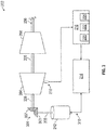
- FIG. 2 illustrates a rotor system 202 that includes at least one compressor section 204 and at least one turbine section 208 operably coupled to a shaft 206.
- the rotor system 202 can be a spool of the gas turbine engine 20 of FIG. 1 , such as the low speed spool 30 or the high speed spool 32.
- the at least one compressor section 204 can be equivalent to the low pressure compressor 44 and may include the fan 42
- the shaft 206 can be equivalent to the inner shaft 40
- the at least one turbine section 208 can be equivalent to the low pressure turbine 46 of FIG. 1 .
- the at least one compressor section 204 can be equivalent to the high pressure compressor 52
- the shaft 206 can be equivalent to the outer shaft 50
- the at least one turbine section 208 can be equivalent to the high pressure turbine 54 of FIG. 1 .
- a compressor surge control system 210 is operably coupled to the rotor system 202.
- the compressor surge control system 210 includes an electric motor 212 directly coupled to the shaft 206.
- the compressor surge control system 210 also includes drive electronics 214 operable to control current to the electric motor 212 to adjust the speed and/or torque of the electric motor 212.
- the electric motor 212 can be a direct current (DC) motor or an alternating current (AC) motor including conventional motor components, such as a motor rotor and motor stator, including a plurality of motor windings and/or permanent magnets.
- the drive electronics 214 can also include conventional motor current control electronics, such as filters, switching components, rectifiers, inverters, and the like.
- the electric motor 212 is a motor-generator operable in a generator mode to increase a load on the rotor system 202 and in a motoring mode to decrease the load of the rotor system 202.
- the drive electronics 214 may include power regulating circuitry and/or power converters to regulate electric power produced by the electric motor 212 in generator mode.
- the electric motor 212 can act as a variable frequency generator in generator mode due to speed fluctuations of rotation of the shaft 206, which may be primarily driven by the at least one turbine section 208.
- the electric motor 212 may be operable as a starter motor to partially or completely power rotation of the shaft 206 in a starting mode of operation (e.g., to start the gas turbine engine 20 of FIG. 1 ). Other uses and functions for the electric motor 212 are contemplated.
- a controller 216 of the compressor surge control system 210 can monitor one or more rotor system sensors 218 while the rotor system 202 is rotating.
- the rotor system sensors 218 can be any type or combination of sensors operable to measure oscillations of the rotor system 202 and the airflow through it.
- the rotor system sensors 218 can include one or more pressure sensors, speed sensors, torque sensors, and the like.
- the rotor system sensors 218 may be located proximate to the at least one compressor section 204, for example to measure pressure or velocity fluctuations within or in the vicinity of the at least one compressor section 204.
- the controller 216 can control a speed and torque of the electric motor 212 through the drive electronics 214.
- the controller 216 may also control other system aspects, such as controlling operation of the gas turbine engine 20 of FIG. 1 .
- the controller 216 can include a processing system 220, a memory system 222, and an input/output interface 224.
- the processing system 220 can include any type or combination of central processing unit (CPU), including one or more of: a microprocessor, a digital signal processor (DSP), a microcontroller, an application specific integrated circuit (ASIC), a field programmable gate array (FPGA), or the like.
- the memory system 222 can store data and instructions that are executed by the processing system 220.
- the memory system 222 may include random access memory (RAM), read only memory (ROM), or other electronic, optical, magnetic, or any other computer readable medium onto which is stored data and algorithms in a non-transitory form.
- RAM random access memory
- ROM read only memory
- the input/output interface 224 is configured to collect sensor data from the one or more rotor system sensors 218 and interface with the drive electronics 214 and/or other systems (not depicted).
- the controller 216 is operable to detect an early-stage compressor surge oscillation of the rotor system 202 based on the sensor data from the one or more rotor system sensors 218. For example, the controller 216 may monitor a rotational speed of the shaft 206 and pressure changes within the at least one compressor section 204 with respect to time. The controller 216 can also monitor one or more torques on the shaft 206, for example, through direct torque measurements from the one or more rotor system sensors 218 or derived torques based on system models and/or known relationships based on mass, acceleration, and/or geometric configuration of the rotor system 202.
- the controller 216 is an example of means for monitoring the one or more rotor system sensors 218 while the rotor system 202 is rotating and means for determining whether the plurality of sensor data from the one or more rotor system sensors 218 is indicative of the early-stage compressor surge oscillation.
- a potential full-scale surge event may begin as initial oscillating air flow pattern within the at least one compressor section 204 that can result in development of an oscillating torque on the shaft 206.
- An appropriate measurement of the spatial distribution of pressure or velocity fluctuations within the compression system is especially useful in detecting embryonic disturbances which can develop into surge. Threshold levels that define the early-stage compressor surge oscillation may be developed experimentally or analytically.
- the early-stage compressor surge oscillation may be defined as 1%, 10%, 20%, 25%, or another predetermined threshold level with respect to a full surge event that may result in a flow reversal through the at least one compressor section 204.
- a model or mapping function e.g., a multi-variate table
- the controller 216 can determine a surge control torque to diminish the early-stage compressor surge oscillation of the rotor system 202 and command the electric motor 212 to apply the surge control torque to the rotor system 202.
- the controller 216 is an example of means for determining an early-stage compressor surge oscillation and means for diminishing the early-stage compressor surge oscillation.
- the controller 216 is also an example of means for determining a surge control torque to diminish the early-stage compressor surge oscillation and means for commanding the electric motor to apply the surge control torque to the rotor system.
- the surge control torque can include a phase, a magnitude, and a sign of one or more torques to diminish the early-stage compressor surge oscillation of the rotor system 202.
- the controller 216 can drive the electric motor 212 to apply one or more torque perturbations to a steady state load of the rotor system 202 to modify the early-stage compressor surge oscillation of the rotor system 202. Further, the controller 216 may operate the electric motor 212 in a generator mode to increase a load on the rotor system 202 and in a motoring mode to decrease the load of the rotor system 202. By damping out early-stage compressor surge oscillations through the electric motor 212, the early-stage compressor surge oscillations of the rotor system 202 can be controlled, thus preventing smaller oscillations from growing in larger surge/flow reversal events. With sufficient authority, the system can also be used to damp fully developed surge oscillations.
- the general form of the mathematical representation of surge oscillatory behavior in compression systems such as gas turbines can be derived from the geometry of the respective system and is well understood. From these representations, robust control laws for a controller can be formatted using standard procedures.
- One such procedure is to excite the compressor 204, for example with air jets installed for this purpose or oscillation of variable stators with the machine.
- the excitation can take several forms, such as: sinusoidal frequency and amplitude sweeps, ramps, stochastic disturbances, and others as is well known.
- the data so generated can then be used to identify the relevant surge dynamics of the engine geometry, most conveniently as separate vibrational modes of the air often described in the form of eigenvectors and eigenvalues. Given this information, many standard mathematical techniques can be employed to formulate both linear and non-linear control laws. Note that this procedure need not be carried out on each engine unit, but may be more capable if done so depending on the geometrical uniformity of the manufacturing and assemble process.
- FIG. 3 a schematic diagram of the rotor system 202 with a compressor surge control system 310 is depicted as an alternate embodiment of the compressor surge control system 210 of FIG. 2 .
- the controller 216 is operable to measure aspects of the motion of the rotor system 202 through one or more rotor system sensors 218 and command the drive electronics 214 to modify a speed and/or torque of the electric motor 212 to apply a surge control torque to the rotor system 202.
- a compressor surge control system 310 of FIG. 3 includes a geared interface 301 that operably couples the electric motor 212 to the shaft 206.
- the geared interface 301 can include, for instance, a motor gear 303 coupled to a motor shaft 305 driven by the electric motor 212.
- the geared interface 301 can also include a rotor gear 307 coupled to the shaft 206.
- the motor gear 303 and the rotor gear 307 can each be beveled gears.
- the motor shaft 305 can be a tower shaft that enables the electric motor 212 to be separated at a greater distance from the rotor system 202 than in the compressor surge control system 210 of FIG. 2 . Further separation of the electric motor 212 from the rotor system 202 can improve accessibility to the electric motor 212 for servicing and may reduce heating effects of the rotor system 202 on the electric motor 212 (e.g., due to fuel combustion).
- Surge control torque computations by the controller 216 can be adjusted to compensate for effects of the geared interface 301, such as gear backlash between the motor gear 303 and the rotor gear 307.
- FIG. 4 is a schematic diagram of a dual rotor system 400 with early-stage compressor surge oscillation damping according to an embodiment.
- the dual rotor system 400 includes a first rotor system 402A and a second rotor system 402B, which may be an embodiment of the gas turbine engine 20 of FIG. 1 .
- the first rotor system 402A can be the low speed spool 30 of the gas turbine engine 20
- the second rotor system 402B can be the high speed spool 32 of the gas turbine engine 20.
- the first rotor system 402A can include a first compressor section 204A and a first turbine section 208A operably coupled to a first shaft 206A.
- the second rotor system 402B can include a second compressor section 204B and a second turbine section 208B operably coupled to a second shaft 206B, where the second shaft 206B is concentrically arranged with respect to the first shaft 206A.
- the first compressor section 204A can be equivalent to the low pressure compressor 44
- the first shaft 206A can be equivalent to the inner shaft 40
- the first turbine section 208A can be equivalent to the low pressure turbine 46 of FIG. 1
- the second compressor section 204B can be equivalent to the high pressure compressor 52
- the second shaft 206B can be equivalent to the outer shaft 50
- the second turbine section 208B can be equivalent to the high pressure turbine 54 of FIG. 1 .
- a compressor surge control system 410 includes a first electric motor 212A driven by first drive electronics 214A and a second electric motor 212B driven by second drive electronics 214B.
- a first set of one or more rotor system sensors 218A may be associated with the first rotor system 402A, and a second set of one or more rotor system sensors 218B may be associated with the second rotor system 402B.
- a single instance of the controller 216 can be configured to independently control the first electric motor 212A responsive to sensor data from the first set of one or more rotor system sensors 218A, and separately control the second electric motor 212B responsive to sensor data from the second set of one or more rotor system sensors 218B.
- the controller 216 is further subdivided as two or more separate controls, for instance, where a separate instance of the controller 216 is provided for each of the first rotor system 402A and the second rotor system 402B.
- the first electric motor 212A and the second electric motor 212B can be independently controlled to each supply a supplemental motive force to the respective shafts 206A, 206B, where fuel combustion in the combustor section 26 ( FIG. 1 ) can provide a primary motive force for the first rotor system 402A as the low speed spool 30 and for the second rotor system 402B as the high speed spool 32.
- the first electric motor 212A is operably coupled to the first shaft 206A using a direct coupling
- the second electric motor 212B is operably coupled to the second shaft 206B using a geared interface 401.
- the geared interface 401 can include, for instance, a motor gear 403 coupled to a motor shaft 405 driven by the second electric motor 212B and a rotor gear 407 coupled to the second shaft 206B. While the example of FIG.
- first and second electric motors 212A, 212B can be directly or indirectly coupled to corresponding first and second shafts 206A, 206B.
- first electric motor 212A may be indirectly coupled through a tower shaft to the first shaft 206A
- second electric motor 212B is directly coupled to the second shaft 206B.
- the coupling locations of the first and second electric motors 212A, 212B to the first and second shafts 206A, 206B can vary, and the coupling locations depicted in FIG. 4 are merely one example.
- FIG. 5 is a flow chart illustrating a method 500 for compressor surge control, in accordance with an embodiment.
- the method 500 may be performed, for example, by the compressor surge control systems 210, 310, 410 of FIGS. 2-4 .
- the method 500 is described primarily with respect to the compressor surge control system 210 of FIG. 2 ; however, it will be understood that the method 500 can be performed on other configurations, such as the compressor surge control systems 310, 410 of FIGS. 3 and 4 , as well as other configurations (not depicted).
- a controller 216 monitors one or more rotor system sensors 218 of a rotor system 202 while the rotor system 202 is rotating. At block 504, the controller 216 determines whether a plurality of sensor data from the one or more rotor system sensors 218 is indicative of an early-stage compressor surge oscillation. At block 506, the controller 216 determines a surge control torque to diminish the early-stage compressor surge oscillation of the rotor system 202.
- the surge control torque can include a phase, a magnitude, and a sign of one or more torques to diminish the early-stage compressor surge oscillation of the rotor system 202.
- the controller 216 commands an electric motor 212 operably coupled to the rotor system 202 to apply the surge control torque to the rotor system 202.
- the electric motor 212 can apply one or more torque perturbations to a steady state load of the rotor system 202 to modify the early-stage compressor surge oscillation of the rotor system 202, for instance, to damp out the early-stage compressor surge oscillation of the rotor system 202.
Landscapes
- Engineering & Computer Science (AREA)
- Mechanical Engineering (AREA)
- General Engineering & Computer Science (AREA)
- Chemical & Material Sciences (AREA)
- Combustion & Propulsion (AREA)
- Power Engineering (AREA)
- Physics & Mathematics (AREA)
- Fluid Mechanics (AREA)
- Control Of Positive-Displacement Air Blowers (AREA)
- Structures Of Non-Positive Displacement Pumps (AREA)
Applications Claiming Priority (1)
| Application Number | Priority Date | Filing Date | Title |
|---|---|---|---|
| US15/992,747 US11319963B2 (en) | 2018-05-30 | 2018-05-30 | Compressor surge control |
Publications (2)
| Publication Number | Publication Date |
|---|---|
| EP3575560A1 true EP3575560A1 (fr) | 2019-12-04 |
| EP3575560B1 EP3575560B1 (fr) | 2024-07-17 |
Family
ID=66647182
Family Applications (1)
| Application Number | Title | Priority Date | Filing Date |
|---|---|---|---|
| EP19176315.0A Active EP3575560B1 (fr) | 2018-05-30 | 2019-05-23 | Contrôle de pompage de compresseur |
Country Status (2)
| Country | Link |
|---|---|
| US (1) | US11319963B2 (fr) |
| EP (1) | EP3575560B1 (fr) |
Cited By (1)
| Publication number | Priority date | Publication date | Assignee | Title |
|---|---|---|---|---|
| EP3812566A1 (fr) * | 2019-07-30 | 2021-04-28 | General Electric Company | Commande de stabilité active de systèmes de compression utilisant des machines électriques |
Families Citing this family (11)
| Publication number | Priority date | Publication date | Assignee | Title |
|---|---|---|---|---|
| EP3101278B1 (fr) * | 2015-06-03 | 2021-04-28 | ABB Schweiz AG | Amortissement actif de vibrations dans un processus de commande |
| WO2018061076A1 (fr) * | 2016-09-27 | 2018-04-05 | 三菱重工コンプレッサ株式会社 | Dispositif de commande et procédé de commande pour machine rotative, et unité de machine rotative équipée d'un dispositif de commande |
| US11215117B2 (en) * | 2019-11-08 | 2022-01-04 | Raytheon Technologies Corporation | Gas turbine engine having electric motor applying power to the high pressure spool shaft and method for operating same |
| US11448138B2 (en) * | 2020-02-06 | 2022-09-20 | Raytheon Technologies Corporation | Surge recovery systems and methods |
| US11739694B2 (en) * | 2020-04-15 | 2023-08-29 | General Electric Company | Embedded electric motor assembly |
| US12516635B2 (en) * | 2020-08-31 | 2026-01-06 | General Electric Company | Compressor stall mitigation |
| US12031479B2 (en) * | 2020-08-31 | 2024-07-09 | General Electric Company | Hybrid electric propulsion system load share |
| US20220252007A1 (en) * | 2021-02-08 | 2022-08-11 | General Electric Company | Active compressor stall recovery |
| US11873081B2 (en) | 2021-06-09 | 2024-01-16 | Textron Innovations Inc. | Supplemental engine power control |
| US12077308B2 (en) | 2022-04-14 | 2024-09-03 | Textron Innovations Inc. | Supplemental engine transition control |
| US12054245B2 (en) * | 2022-07-18 | 2024-08-06 | Textron Innovations Inc. | Optimizing usage of supplemental engine power |
Citations (5)
| Publication number | Priority date | Publication date | Assignee | Title |
|---|---|---|---|---|
| US20020158517A1 (en) * | 2000-11-14 | 2002-10-31 | Rouse Gregory C. | Method and apparatus for turbogenerator anti-surge control |
| US20060042252A1 (en) * | 2004-08-25 | 2006-03-02 | Honeywell International, Inc. | Engine power extraction control system |
| EP1712761A2 (fr) * | 2005-04-08 | 2006-10-18 | United Technologies Corporation | Turbine à gaz à deux corps couplée électriquement |
| EP2657457A2 (fr) * | 2012-04-27 | 2013-10-30 | IHI Aerospace Co., Ltd. | Système de génération d'électricité |
| EP3246528A1 (fr) * | 2016-05-18 | 2017-11-22 | Rolls-Royce Corporation | Générateur basse pression ayant un ensemble électrique pour moteur à turbine à gaz |
Family Cites Families (9)
| Publication number | Priority date | Publication date | Assignee | Title |
|---|---|---|---|---|
| US4177649A (en) | 1977-11-01 | 1979-12-11 | Borg-Warner Corporation | Surge suppression apparatus for compressor-driven system |
| US5082421A (en) * | 1986-04-28 | 1992-01-21 | Rolls-Royce Plc | Active control of unsteady motion phenomena in turbomachinery |
| US6871487B2 (en) | 2003-02-14 | 2005-03-29 | Kulite Semiconductor Products, Inc. | System for detecting and compensating for aerodynamic instabilities in turbo-jet engines |
| US6871498B1 (en) | 2003-12-20 | 2005-03-29 | Honeywell International, Inc. | Compressor surge protector for electric assisted turbocharger |
| US7159401B1 (en) | 2004-12-23 | 2007-01-09 | Kulite Semiconductor Products, Inc. | System for detecting and compensating for aerodynamic instabilities in turbo-jet engines |
| US9500200B2 (en) * | 2012-04-19 | 2016-11-22 | General Electric Company | Systems and methods for detecting the onset of compressor stall |
| EP3101278B1 (fr) | 2015-06-03 | 2021-04-28 | ABB Schweiz AG | Amortissement actif de vibrations dans un processus de commande |
| US10336461B2 (en) * | 2016-01-05 | 2019-07-02 | The Boeing Company | Aircraft engine and associated method for driving the fan with the low pressure shaft during taxi operations |
| US9981654B2 (en) | 2016-06-02 | 2018-05-29 | Ford Global Technologies, Llc | Methods and systems for surge control |
-
2018
- 2018-05-30 US US15/992,747 patent/US11319963B2/en active Active
-
2019
- 2019-05-23 EP EP19176315.0A patent/EP3575560B1/fr active Active
Patent Citations (5)
| Publication number | Priority date | Publication date | Assignee | Title |
|---|---|---|---|---|
| US20020158517A1 (en) * | 2000-11-14 | 2002-10-31 | Rouse Gregory C. | Method and apparatus for turbogenerator anti-surge control |
| US20060042252A1 (en) * | 2004-08-25 | 2006-03-02 | Honeywell International, Inc. | Engine power extraction control system |
| EP1712761A2 (fr) * | 2005-04-08 | 2006-10-18 | United Technologies Corporation | Turbine à gaz à deux corps couplée électriquement |
| EP2657457A2 (fr) * | 2012-04-27 | 2013-10-30 | IHI Aerospace Co., Ltd. | Système de génération d'électricité |
| EP3246528A1 (fr) * | 2016-05-18 | 2017-11-22 | Rolls-Royce Corporation | Générateur basse pression ayant un ensemble électrique pour moteur à turbine à gaz |
Cited By (1)
| Publication number | Priority date | Publication date | Assignee | Title |
|---|---|---|---|---|
| EP3812566A1 (fr) * | 2019-07-30 | 2021-04-28 | General Electric Company | Commande de stabilité active de systèmes de compression utilisant des machines électriques |
Also Published As
| Publication number | Publication date |
|---|---|
| US11319963B2 (en) | 2022-05-03 |
| EP3575560B1 (fr) | 2024-07-17 |
| US20190368500A1 (en) | 2019-12-05 |
Similar Documents
| Publication | Publication Date | Title |
|---|---|---|
| EP3575560B1 (fr) | Contrôle de pompage de compresseur | |
| EP3862569B1 (fr) | Sortie de pompage de compresseur de turbine à gaz par l'intermédiaire d'un moteur électrique | |
| EP3693571B1 (fr) | Commande de fonctionnement transitoire d'un moteur à turbine à gaz hybride | |
| EP3573228B1 (fr) | Amortissement dynamique de rotor électrique | |
| US11999498B2 (en) | Variable cycle compensation in a gas turbine engine | |
| EP3779147B1 (fr) | Adaptation dynamique du rotor à l'aide de l'assistance électrique | |
| EP3290653B1 (fr) | Identification d'un paramètre de système dynamique pour turbomachine | |
| US20220065688A1 (en) | System and method for detecting vibrations in rotating machinery | |
| US20190186368A1 (en) | Method of Starting a Gas Turbine Engine | |
| US11557995B2 (en) | Aircraft engine power-assist start stability control | |
| US12388321B2 (en) | Gas turbine engine equipped with a control system for management of rotor modes using an electric machine | |
| EP2971651B1 (fr) | Procédés de fonctionnement d'une turbine à gaz | |
| CN115126554B (zh) | 配有使用电机管理转子模式的控制系统的燃气涡轮发动机 |
Legal Events
| Date | Code | Title | Description |
|---|---|---|---|
| PUAI | Public reference made under article 153(3) epc to a published international application that has entered the european phase |
Free format text: ORIGINAL CODE: 0009012 |
|
| STAA | Information on the status of an ep patent application or granted ep patent |
Free format text: STATUS: THE APPLICATION HAS BEEN PUBLISHED |
|
| AK | Designated contracting states |
Kind code of ref document: A1 Designated state(s): AL AT BE BG CH CY CZ DE DK EE ES FI FR GB GR HR HU IE IS IT LI LT LU LV MC MK MT NL NO PL PT RO RS SE SI SK SM TR |
|
| AX | Request for extension of the european patent |
Extension state: BA ME |
|
| STAA | Information on the status of an ep patent application or granted ep patent |
Free format text: STATUS: REQUEST FOR EXAMINATION WAS MADE |
|
| 17P | Request for examination filed |
Effective date: 20200604 |
|
| RBV | Designated contracting states (corrected) |
Designated state(s): AL AT BE BG CH CY CZ DE DK EE ES FI FR GB GR HR HU IE IS IT LI LT LU LV MC MK MT NL NO PL PT RO RS SE SI SK SM TR |
|
| RAP1 | Party data changed (applicant data changed or rights of an application transferred) |
Owner name: RAYTHEON TECHNOLOGIES CORPORATION |
|
| STAA | Information on the status of an ep patent application or granted ep patent |
Free format text: STATUS: EXAMINATION IS IN PROGRESS |
|
| 17Q | First examination report despatched |
Effective date: 20220401 |
|
| RAP3 | Party data changed (applicant data changed or rights of an application transferred) |
Owner name: RTX CORPORATION |
|
| GRAP | Despatch of communication of intention to grant a patent |
Free format text: ORIGINAL CODE: EPIDOSNIGR1 |
|
| STAA | Information on the status of an ep patent application or granted ep patent |
Free format text: STATUS: GRANT OF PATENT IS INTENDED |
|
| INTG | Intention to grant announced |
Effective date: 20240208 |
|
| GRAS | Grant fee paid |
Free format text: ORIGINAL CODE: EPIDOSNIGR3 |
|
| GRAA | (expected) grant |
Free format text: ORIGINAL CODE: 0009210 |
|
| STAA | Information on the status of an ep patent application or granted ep patent |
Free format text: STATUS: THE PATENT HAS BEEN GRANTED |
|
| AK | Designated contracting states |
Kind code of ref document: B1 Designated state(s): AL AT BE BG CH CY CZ DE DK EE ES FI FR GB GR HR HU IE IS IT LI LT LU LV MC MK MT NL NO PL PT RO RS SE SI SK SM TR |
|
| REG | Reference to a national code |
Ref country code: CH Ref legal event code: EP |
|
| REG | Reference to a national code |
Ref country code: DE Ref legal event code: R096 Ref document number: 602019055266 Country of ref document: DE |
|
| REG | Reference to a national code |
Ref country code: IE Ref legal event code: FG4D |
|
| REG | Reference to a national code |
Ref country code: LT Ref legal event code: MG9D |
|
| REG | Reference to a national code |
Ref country code: NL Ref legal event code: MP Effective date: 20240717 |
|
| PG25 | Lapsed in a contracting state [announced via postgrant information from national office to epo] |
Ref country code: PT Free format text: LAPSE BECAUSE OF FAILURE TO SUBMIT A TRANSLATION OF THE DESCRIPTION OR TO PAY THE FEE WITHIN THE PRESCRIBED TIME-LIMIT Effective date: 20241118 |
|
| REG | Reference to a national code |
Ref country code: AT Ref legal event code: MK05 Ref document number: 1704331 Country of ref document: AT Kind code of ref document: T Effective date: 20240717 |
|
| PG25 | Lapsed in a contracting state [announced via postgrant information from national office to epo] |
Ref country code: NL Free format text: LAPSE BECAUSE OF FAILURE TO SUBMIT A TRANSLATION OF THE DESCRIPTION OR TO PAY THE FEE WITHIN THE PRESCRIBED TIME-LIMIT Effective date: 20240717 |
|
| PG25 | Lapsed in a contracting state [announced via postgrant information from national office to epo] |
Ref country code: PT Free format text: LAPSE BECAUSE OF FAILURE TO SUBMIT A TRANSLATION OF THE DESCRIPTION OR TO PAY THE FEE WITHIN THE PRESCRIBED TIME-LIMIT Effective date: 20241118 Ref country code: NL Free format text: LAPSE BECAUSE OF FAILURE TO SUBMIT A TRANSLATION OF THE DESCRIPTION OR TO PAY THE FEE WITHIN THE PRESCRIBED TIME-LIMIT Effective date: 20240717 |
|
| PG25 | Lapsed in a contracting state [announced via postgrant information from national office to epo] |
Ref country code: NO Free format text: LAPSE BECAUSE OF FAILURE TO SUBMIT A TRANSLATION OF THE DESCRIPTION OR TO PAY THE FEE WITHIN THE PRESCRIBED TIME-LIMIT Effective date: 20241017 |
|
| PG25 | Lapsed in a contracting state [announced via postgrant information from national office to epo] |
Ref country code: FI Free format text: LAPSE BECAUSE OF FAILURE TO SUBMIT A TRANSLATION OF THE DESCRIPTION OR TO PAY THE FEE WITHIN THE PRESCRIBED TIME-LIMIT Effective date: 20240717 Ref country code: GR Free format text: LAPSE BECAUSE OF FAILURE TO SUBMIT A TRANSLATION OF THE DESCRIPTION OR TO PAY THE FEE WITHIN THE PRESCRIBED TIME-LIMIT Effective date: 20241018 Ref country code: PL Free format text: LAPSE BECAUSE OF FAILURE TO SUBMIT A TRANSLATION OF THE DESCRIPTION OR TO PAY THE FEE WITHIN THE PRESCRIBED TIME-LIMIT Effective date: 20240717 |
|
| PG25 | Lapsed in a contracting state [announced via postgrant information from national office to epo] |
Ref country code: BG Free format text: LAPSE BECAUSE OF FAILURE TO SUBMIT A TRANSLATION OF THE DESCRIPTION OR TO PAY THE FEE WITHIN THE PRESCRIBED TIME-LIMIT Effective date: 20240717 |
|
| PG25 | Lapsed in a contracting state [announced via postgrant information from national office to epo] |
Ref country code: LV Free format text: LAPSE BECAUSE OF FAILURE TO SUBMIT A TRANSLATION OF THE DESCRIPTION OR TO PAY THE FEE WITHIN THE PRESCRIBED TIME-LIMIT Effective date: 20240717 |
|
| PG25 | Lapsed in a contracting state [announced via postgrant information from national office to epo] |
Ref country code: IS Free format text: LAPSE BECAUSE OF FAILURE TO SUBMIT A TRANSLATION OF THE DESCRIPTION OR TO PAY THE FEE WITHIN THE PRESCRIBED TIME-LIMIT Effective date: 20241117 Ref country code: AT Free format text: LAPSE BECAUSE OF FAILURE TO SUBMIT A TRANSLATION OF THE DESCRIPTION OR TO PAY THE FEE WITHIN THE PRESCRIBED TIME-LIMIT Effective date: 20240717 |
|
| PG25 | Lapsed in a contracting state [announced via postgrant information from national office to epo] |
Ref country code: HR Free format text: LAPSE BECAUSE OF FAILURE TO SUBMIT A TRANSLATION OF THE DESCRIPTION OR TO PAY THE FEE WITHIN THE PRESCRIBED TIME-LIMIT Effective date: 20240717 |
|
| PG25 | Lapsed in a contracting state [announced via postgrant information from national office to epo] |
Ref country code: ES Free format text: LAPSE BECAUSE OF FAILURE TO SUBMIT A TRANSLATION OF THE DESCRIPTION OR TO PAY THE FEE WITHIN THE PRESCRIBED TIME-LIMIT Effective date: 20240717 Ref country code: RS Free format text: LAPSE BECAUSE OF FAILURE TO SUBMIT A TRANSLATION OF THE DESCRIPTION OR TO PAY THE FEE WITHIN THE PRESCRIBED TIME-LIMIT Effective date: 20241017 |
|
| PG25 | Lapsed in a contracting state [announced via postgrant information from national office to epo] |
Ref country code: RS Free format text: LAPSE BECAUSE OF FAILURE TO SUBMIT A TRANSLATION OF THE DESCRIPTION OR TO PAY THE FEE WITHIN THE PRESCRIBED TIME-LIMIT Effective date: 20241017 Ref country code: PL Free format text: LAPSE BECAUSE OF FAILURE TO SUBMIT A TRANSLATION OF THE DESCRIPTION OR TO PAY THE FEE WITHIN THE PRESCRIBED TIME-LIMIT Effective date: 20240717 Ref country code: NO Free format text: LAPSE BECAUSE OF FAILURE TO SUBMIT A TRANSLATION OF THE DESCRIPTION OR TO PAY THE FEE WITHIN THE PRESCRIBED TIME-LIMIT Effective date: 20241017 Ref country code: LV Free format text: LAPSE BECAUSE OF FAILURE TO SUBMIT A TRANSLATION OF THE DESCRIPTION OR TO PAY THE FEE WITHIN THE PRESCRIBED TIME-LIMIT Effective date: 20240717 Ref country code: IS Free format text: LAPSE BECAUSE OF FAILURE TO SUBMIT A TRANSLATION OF THE DESCRIPTION OR TO PAY THE FEE WITHIN THE PRESCRIBED TIME-LIMIT Effective date: 20241117 Ref country code: HR Free format text: LAPSE BECAUSE OF FAILURE TO SUBMIT A TRANSLATION OF THE DESCRIPTION OR TO PAY THE FEE WITHIN THE PRESCRIBED TIME-LIMIT Effective date: 20240717 Ref country code: GR Free format text: LAPSE BECAUSE OF FAILURE TO SUBMIT A TRANSLATION OF THE DESCRIPTION OR TO PAY THE FEE WITHIN THE PRESCRIBED TIME-LIMIT Effective date: 20241018 Ref country code: FI Free format text: LAPSE BECAUSE OF FAILURE TO SUBMIT A TRANSLATION OF THE DESCRIPTION OR TO PAY THE FEE WITHIN THE PRESCRIBED TIME-LIMIT Effective date: 20240717 Ref country code: ES Free format text: LAPSE BECAUSE OF FAILURE TO SUBMIT A TRANSLATION OF THE DESCRIPTION OR TO PAY THE FEE WITHIN THE PRESCRIBED TIME-LIMIT Effective date: 20240717 Ref country code: BG Free format text: LAPSE BECAUSE OF FAILURE TO SUBMIT A TRANSLATION OF THE DESCRIPTION OR TO PAY THE FEE WITHIN THE PRESCRIBED TIME-LIMIT Effective date: 20240717 Ref country code: AT Free format text: LAPSE BECAUSE OF FAILURE TO SUBMIT A TRANSLATION OF THE DESCRIPTION OR TO PAY THE FEE WITHIN THE PRESCRIBED TIME-LIMIT Effective date: 20240717 |
|
| PG25 | Lapsed in a contracting state [announced via postgrant information from national office to epo] |
Ref country code: RO Free format text: LAPSE BECAUSE OF FAILURE TO SUBMIT A TRANSLATION OF THE DESCRIPTION OR TO PAY THE FEE WITHIN THE PRESCRIBED TIME-LIMIT Effective date: 20240717 Ref country code: SM Free format text: LAPSE BECAUSE OF FAILURE TO SUBMIT A TRANSLATION OF THE DESCRIPTION OR TO PAY THE FEE WITHIN THE PRESCRIBED TIME-LIMIT Effective date: 20240717 Ref country code: DK Free format text: LAPSE BECAUSE OF FAILURE TO SUBMIT A TRANSLATION OF THE DESCRIPTION OR TO PAY THE FEE WITHIN THE PRESCRIBED TIME-LIMIT Effective date: 20240717 |
|
| REG | Reference to a national code |
Ref country code: DE Ref legal event code: R097 Ref document number: 602019055266 Country of ref document: DE |
|
| PG25 | Lapsed in a contracting state [announced via postgrant information from national office to epo] |
Ref country code: EE Free format text: LAPSE BECAUSE OF FAILURE TO SUBMIT A TRANSLATION OF THE DESCRIPTION OR TO PAY THE FEE WITHIN THE PRESCRIBED TIME-LIMIT Effective date: 20240717 |
|
| PG25 | Lapsed in a contracting state [announced via postgrant information from national office to epo] |
Ref country code: CZ Free format text: LAPSE BECAUSE OF FAILURE TO SUBMIT A TRANSLATION OF THE DESCRIPTION OR TO PAY THE FEE WITHIN THE PRESCRIBED TIME-LIMIT Effective date: 20240717 |
|
| PG25 | Lapsed in a contracting state [announced via postgrant information from national office to epo] |
Ref country code: SK Free format text: LAPSE BECAUSE OF FAILURE TO SUBMIT A TRANSLATION OF THE DESCRIPTION OR TO PAY THE FEE WITHIN THE PRESCRIBED TIME-LIMIT Effective date: 20240717 |
|
| PLBE | No opposition filed within time limit |
Free format text: ORIGINAL CODE: 0009261 |
|
| STAA | Information on the status of an ep patent application or granted ep patent |
Free format text: STATUS: NO OPPOSITION FILED WITHIN TIME LIMIT |
|
| 26N | No opposition filed |
Effective date: 20250422 |
|
| PGFP | Annual fee paid to national office [announced via postgrant information from national office to epo] |
Ref country code: DE Payment date: 20250423 Year of fee payment: 7 |
|
| PGFP | Annual fee paid to national office [announced via postgrant information from national office to epo] |
Ref country code: GB Payment date: 20250423 Year of fee payment: 7 |
|
| PGFP | Annual fee paid to national office [announced via postgrant information from national office to epo] |
Ref country code: FR Payment date: 20250423 Year of fee payment: 7 |
|
| PG25 | Lapsed in a contracting state [announced via postgrant information from national office to epo] |
Ref country code: SE Free format text: LAPSE BECAUSE OF FAILURE TO SUBMIT A TRANSLATION OF THE DESCRIPTION OR TO PAY THE FEE WITHIN THE PRESCRIBED TIME-LIMIT Effective date: 20240717 |
|
| REG | Reference to a national code |
Ref country code: CH Ref legal event code: H13 Free format text: ST27 STATUS EVENT CODE: U-0-0-H10-H13 (AS PROVIDED BY THE NATIONAL OFFICE) Effective date: 20251223 |
|
| PG25 | Lapsed in a contracting state [announced via postgrant information from national office to epo] |
Ref country code: LU Free format text: LAPSE BECAUSE OF NON-PAYMENT OF DUE FEES Effective date: 20250523 |
|
| PG25 | Lapsed in a contracting state [announced via postgrant information from national office to epo] |
Ref country code: CH Free format text: LAPSE BECAUSE OF NON-PAYMENT OF DUE FEES Effective date: 20250531 |
|
| PG25 | Lapsed in a contracting state [announced via postgrant information from national office to epo] |
Ref country code: IT Free format text: LAPSE BECAUSE OF FAILURE TO SUBMIT A TRANSLATION OF THE DESCRIPTION OR TO PAY THE FEE WITHIN THE PRESCRIBED TIME-LIMIT Effective date: 20240717 |
|
| REG | Reference to a national code |
Ref country code: BE Ref legal event code: MM Effective date: 20250531 |
|
| PG25 | Lapsed in a contracting state [announced via postgrant information from national office to epo] |
Ref country code: MC Free format text: LAPSE BECAUSE OF FAILURE TO SUBMIT A TRANSLATION OF THE DESCRIPTION OR TO PAY THE FEE WITHIN THE PRESCRIBED TIME-LIMIT Effective date: 20240717 |
|
| PG25 | Lapsed in a contracting state [announced via postgrant information from national office to epo] |
Ref country code: IE Free format text: LAPSE BECAUSE OF NON-PAYMENT OF DUE FEES Effective date: 20250523 |
|
| PG25 | Lapsed in a contracting state [announced via postgrant information from national office to epo] |
Ref country code: BE Free format text: LAPSE BECAUSE OF NON-PAYMENT OF DUE FEES Effective date: 20250531 |