EP3575657A1 - Verbundrohr - Google Patents
Verbundrohr Download PDFInfo
- Publication number
- EP3575657A1 EP3575657A1 EP17887630.6A EP17887630A EP3575657A1 EP 3575657 A1 EP3575657 A1 EP 3575657A1 EP 17887630 A EP17887630 A EP 17887630A EP 3575657 A1 EP3575657 A1 EP 3575657A1
- Authority
- EP
- European Patent Office
- Prior art keywords
- covering layer
- pipe body
- composite pipe
- portions
- layer
- Prior art date
- Legal status (The legal status is an assumption and is not a legal conclusion. Google has not performed a legal analysis and makes no representation as to the accuracy of the status listed.)
- Withdrawn
Links
- 239000002131 composite material Substances 0.000 title claims abstract description 80
- -1 polyethylene Polymers 0.000 claims abstract description 25
- 239000004698 Polyethylene Substances 0.000 claims abstract description 22
- 229920000573 polyethylene Polymers 0.000 claims abstract description 22
- 230000000994 depressogenic effect Effects 0.000 claims abstract description 6
- 239000000155 melt Substances 0.000 claims description 4
- 229920005989 resin Polymers 0.000 description 54
- 239000011347 resin Substances 0.000 description 54
- 239000000463 material Substances 0.000 description 29
- 238000004519 manufacturing process Methods 0.000 description 20
- 238000004904 shortening Methods 0.000 description 16
- 230000000052 comparative effect Effects 0.000 description 15
- 238000000034 method Methods 0.000 description 13
- 239000011342 resin composition Substances 0.000 description 11
- 229920001083 polybutene Polymers 0.000 description 10
- 229920005830 Polyurethane Foam Polymers 0.000 description 8
- 230000008602 contraction Effects 0.000 description 8
- 239000011496 polyurethane foam Substances 0.000 description 8
- 229920001684 low density polyethylene Polymers 0.000 description 7
- 239000004702 low-density polyethylene Substances 0.000 description 7
- 238000005259 measurement Methods 0.000 description 6
- 238000012360 testing method Methods 0.000 description 6
- 238000013459 approach Methods 0.000 description 5
- 238000001816 cooling Methods 0.000 description 5
- 238000011156 evaluation Methods 0.000 description 5
- 229920001903 high density polyethylene Polymers 0.000 description 5
- 239000004700 high-density polyethylene Substances 0.000 description 5
- 229920002635 polyurethane Polymers 0.000 description 4
- 239000004814 polyurethane Substances 0.000 description 4
- 230000008961 swelling Effects 0.000 description 4
- 239000004743 Polypropylene Substances 0.000 description 3
- 239000000654 additive Substances 0.000 description 3
- 230000000996 additive effect Effects 0.000 description 3
- 230000015572 biosynthetic process Effects 0.000 description 3
- 230000008878 coupling Effects 0.000 description 3
- 238000010168 coupling process Methods 0.000 description 3
- 238000005859 coupling reaction Methods 0.000 description 3
- 239000006260 foam Substances 0.000 description 3
- 229920000098 polyolefin Polymers 0.000 description 3
- 229920001155 polypropylene Polymers 0.000 description 3
- 239000011148 porous material Substances 0.000 description 3
- 239000002994 raw material Substances 0.000 description 3
- 238000011144 upstream manufacturing Methods 0.000 description 3
- BZHJMEDXRYGGRV-UHFFFAOYSA-N Vinyl chloride Chemical compound ClC=C BZHJMEDXRYGGRV-UHFFFAOYSA-N 0.000 description 2
- 238000004891 communication Methods 0.000 description 2
- 230000006835 compression Effects 0.000 description 2
- 238000007906 compression Methods 0.000 description 2
- 239000000470 constituent Substances 0.000 description 2
- 235000012438 extruded product Nutrition 0.000 description 2
- 239000000203 mixture Substances 0.000 description 2
- 239000000178 monomer Substances 0.000 description 2
- 238000009751 slip forming Methods 0.000 description 2
- 238000004804 winding Methods 0.000 description 2
- VGGSQFUCUMXWEO-UHFFFAOYSA-N Ethene Chemical compound C=C VGGSQFUCUMXWEO-UHFFFAOYSA-N 0.000 description 1
- 239000005977 Ethylene Substances 0.000 description 1
- 239000004793 Polystyrene Substances 0.000 description 1
- 230000004323 axial length Effects 0.000 description 1
- 238000005452 bending Methods 0.000 description 1
- 239000003054 catalyst Substances 0.000 description 1
- 239000004703 cross-linked polyethylene Substances 0.000 description 1
- 229920003020 cross-linked polyethylene Polymers 0.000 description 1
- 238000005520 cutting process Methods 0.000 description 1
- 238000010586 diagram Methods 0.000 description 1
- 229920003244 diene elastomer Polymers 0.000 description 1
- 238000011549 displacement method Methods 0.000 description 1
- 238000006073 displacement reaction Methods 0.000 description 1
- 230000000694 effects Effects 0.000 description 1
- NBVXSUQYWXRMNV-UHFFFAOYSA-N fluoromethane Chemical compound FC NBVXSUQYWXRMNV-UHFFFAOYSA-N 0.000 description 1
- 239000004088 foaming agent Substances 0.000 description 1
- 239000010410 layer Substances 0.000 description 1
- 238000000465 moulding Methods 0.000 description 1
- 230000000149 penetrating effect Effects 0.000 description 1
- 230000035515 penetration Effects 0.000 description 1
- 239000005056 polyisocyanate Substances 0.000 description 1
- 229920001228 polyisocyanate Polymers 0.000 description 1
- 229920005862 polyol Polymers 0.000 description 1
- 150000003077 polyols Chemical class 0.000 description 1
- 229920002223 polystyrene Polymers 0.000 description 1
- 229920000915 polyvinyl chloride Polymers 0.000 description 1
- 239000004800 polyvinyl chloride Substances 0.000 description 1
- 238000003825 pressing Methods 0.000 description 1
- 230000000717 retained effect Effects 0.000 description 1
- 239000003381 stabilizer Substances 0.000 description 1
- 229920003002 synthetic resin Polymers 0.000 description 1
- 239000000057 synthetic resin Substances 0.000 description 1
- XLYOFNOQVPJJNP-UHFFFAOYSA-N water Substances O XLYOFNOQVPJJNP-UHFFFAOYSA-N 0.000 description 1
Images




Classifications
-
- H—ELECTRICITY
- H02—GENERATION; CONVERSION OR DISTRIBUTION OF ELECTRIC POWER
- H02G—INSTALLATION OF ELECTRIC CABLES OR LINES, OR OF COMBINED OPTICAL AND ELECTRIC CABLES OR LINES
- H02G3/00—Installations of electric cables or lines or protective tubing therefor in or on buildings, equivalent structures or vehicles
- H02G3/02—Details
- H02G3/04—Protective tubing or conduits, e.g. cable ladders or cable troughs
- H02G3/0462—Tubings, i.e. having a closed section
- H02G3/0468—Corrugated
-
- B—PERFORMING OPERATIONS; TRANSPORTING
- B32—LAYERED PRODUCTS
- B32B—LAYERED PRODUCTS, i.e. PRODUCTS BUILT-UP OF STRATA OF FLAT OR NON-FLAT, e.g. CELLULAR OR HONEYCOMB, FORM
- B32B1/00—Layered products having a non-planar shape
- B32B1/08—Tubular products
-
- F—MECHANICAL ENGINEERING; LIGHTING; HEATING; WEAPONS; BLASTING
- F16—ENGINEERING ELEMENTS AND UNITS; GENERAL MEASURES FOR PRODUCING AND MAINTAINING EFFECTIVE FUNCTIONING OF MACHINES OR INSTALLATIONS; THERMAL INSULATION IN GENERAL
- F16L—PIPES; JOINTS OR FITTINGS FOR PIPES; SUPPORTS FOR PIPES, CABLES OR PROTECTIVE TUBING; MEANS FOR THERMAL INSULATION IN GENERAL
- F16L11/00—Hoses, i.e. flexible pipes
- F16L11/04—Hoses, i.e. flexible pipes made of rubber or flexible plastics
- F16L11/11—Hoses, i.e. flexible pipes made of rubber or flexible plastics with corrugated wall
Definitions
- the present disclosure relates to a composite pipe having a multilayer structure.
- Patent Literature 1 discloses a corrugated pipe for a wiring or piping material, through which the wiring or piping material is inserted, and at least the inner side of which is formed of a polyolefin synthetic resin or vinyl chloride resin mixed with a fluorocarbon resin.
- Patent Literature 1 Japanese Patent Application Laid-Open ( JP-A) No. 2015-48909
- Patent Literature 1 a composite pipe which has an inner pipe body and a bellows-like covering layer covering the outer circumferential surface of the pipe body has been known. Further, with respect to a composite pipe having a pipe body and a covering layer, a configuration in which an intermediate layer is disposed as a buffer layer between the pipe body and the covering layer in order to increase the shock-absorbing property is also conceivable. Meanwhile, with respect to such a composite pipe, when a coupling or the like is connected to an end of the internal pipe body, it is required to move the covering layer to expose an end of the pipe body.
- the covering layer covering the pipe body is required to have ease of expansion and contraction (peeling properties) enabling the covering layer to be easily expanded and contracted in the axial direction of the pipe body.
- an object of the present disclosure is to provide a composite pipe including a pipe body having a tubular shape and a covering layer that has a tubular shape and covers an outer circumferential surface of the pipe body, having a covering layer with excellent ease of expansion and contraction.
- a composite pipe including a pipe body having a tubular shape and a covering layer that has a tubular shape and covers an outer circumferential surface of the pipe body, having a covering layer with excellent ease of expansion and contraction.
- the "main component” herein refers to a component having the highest content on a mass basis in a mixture, unless particularly noted.
- the composite pipe according to the present embodiment has a pipe body having a tubular shape and a covering layer having a tubular shape and covering an outer circumferential surface of the pipe body.
- the covering layer has a bellows shape with annular ridge portions protruding outwardly in a radial direction and annular groove portions depressed inwardly in the radial direction, the annular ridge portions and the annular groove portions being alternately formed in an axial direction of the pipe body, and the covering layer is shortenable in the axal direction of the pipe body by being guided along the outer circumferential surface of the pipe body.
- the covering layer contains polyethylene as a main component, and has a density of from 915 kg/m 3 to 940 kg/m 3 .
- the density of the covering layer is 940 kg/m 3 or less.
- the covering layer can have appropriate flexibility, and when attempting to expose an end of the pipe body, the covering layer can be easily shortened and peeled, so that an end of the pipe body can be easily exposed.
- the covering layer has a density of 915 kg/m 3 or more, the strength of the covering layer can be appropriate, and excellent protection of the surface of the outer circumference of the composite pipe may be achieved.
- the density of the covering layer is more preferably from 918 kg/m 3 to 935 kg/m 3 , and further preferably from 920 kg/m 3 to 930 kg/m 3 .
- the density of the covering layer can be here measured according to "A method (water displacement method)" prescribed in JIS-K7112 (1999).
- the method of controlling the density of the covering layer there is no particular restriction on the method of controlling the density of the covering layer within the above range, and examples thereof include a method of adjusting the molecular structure of polyethylene contained as a main component in the covering layer (that is, a method of adjusting the molecular structure of a monomer serving as a raw material of polyethylene and/or the cross-linked structure thereof), and a method of adjusting the molecular weight of polyethylene.
- melt flow rate (MFR) of the covering layer is from 0.25 to 0.8.
- the MFR of the covering layer is more preferably from 0.30 to 0.6, and further preferably from 0.35 to 0.5.
- Production of a composite pipe having a pipe body and a bellows-shaped covering layer covering the pipe body is performed, for example, by applying a molten product of a resin composition for forming a covering layer on the outer circumferential surface of the pipe body, and solidifying the molten product while forming it into a bellows shape.
- a composite pipe having an intermediate layer between the pipe body and the covering layer is produced, for example, production is performed by winding a sheet to form the intermediate layer around the outer circumferential surface of the pipe body, applying further a molten product of a resin composition for forming a covering layer on the outer circumferential surface of the intermediate layer in such a condition, and solidifying the molten product while forming it into a bellows shape.
- a method for forming the molten product of the resin composition for forming a covering layer into a bellows shape, a method is conceivable by which a pair of molds each having a semi-arc inner surface with a bellows shape are made to approach the outer circumferential surface of the molten product from two directions to come into contact, such that the molten product is solidified to form a bellows shape.
- the molten product of the resin composition has high fluidity from the viewpoint of ease of application.
- the molten product may not be fully accommodated inside the molds, and it may flow into a contact portion of the pair of the molds which the molten product should not normally reach. In such a case, burr may be generated outside the solidified covering layer.
- the fluidity of a molten product may be controlled in an appropriate range, flowing of the molten product into a contact portion of the pair of molds is inhibited, and formation of burr outward in a radial direction on the covering layer is likely to be inhibited. Therefore, it may be inhibited that burr becomes an obstacle to the movement for shortening and displacement of the covering layer in order to expose an end of the pipe body, and ease of expansion and contraction (peeling properties) can be superior.
- a step of removing any burr generated outward in the radial direction on the covering layer may be omitted and complicated manufacturing process of the composite pipe can be avoided.
- the MFR of covering layer is 0.25 or more
- ease of applying the molten product of a resin composition for forming a covering layer onto the outer circumferential surface of a pipe body and/or the outer circumferential surface of an intermediate layer is obtained.
- the resin of the covering layer can be easy to enter a porous structure of the porous resin layer, thereby resulting in an enhancement in the degree of adhesion of the intermediate layer and the groove portions of the covering layer described later.
- the MFR of the covering layer here corresponds to a value obtained by measurement in conditions of a temperature of 190°C and a load of 2.16 kg according to the method prescribed in JIS K7210-1 (2014).
- the method of controlling the MFR of the covering layer within the above range is not particularly limited, and examples include a method of adjusting the molecular structure of polyethylene included as a main component in the covering layer (namely, adjusting the molecular structure of a monomer serving as a raw material of polyethylene, and/or a crosslinked structure thereof) and a method of adjusting the molecular weight of polyethylene.
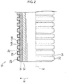
- a composite pipe 10 according to the present embodiment shown in FIG. 1 includes a pipe body 12 and a covering layer 20 covering the outer circumferential surface of the pipe body, and further an intermediate layer 14 is disposed between the pipe body 12 and the covering layer 20.
- the symbol S represents the axis of the pipe body 12, and its axial direction.
- the pipe body 12 has a tubular shape.
- the pipe body is composed of, for example, a resin material containing a resin.
- the resin in the resin material include polyolefins such as polybutene, polyethylene, crosslinked polyethylene, and polypropylene, and vinyl chloride, and such resins may be used singly, or in combination of two or more kinds thereof
- polybutene is suitably used
- the resin preferably includes polybutene as a main component, and, for example, the resin material included in the pipe body can includes 85% by mass or more of polybutene.
- the resin material included in the pipe body may be a material made of only the resin, or may contain other additive(s), provided that the resin is included as a main component.
- the covering layer 20 has a tubular shape, and covers the outer circumferential surfaces of the pipe body 12 and the intermediate layer 14.
- the intermediate layer 14 is disposed between the pipe body 12 and the covering layer 20.
- the covering layer has a density of from 915 kg/m 3 to 940 kg/m 3 .
- a melt flow rate (MFR) of the covering layer is preferably from 0.25 to 0.8.
- the covering layer is composed of a resin material containing a resin, and contains polyethylene as a main component.
- the resin material composing the covering layer contains polyethylene preferably at 80% by mass or more, and more preferably at 90% by mass or more.
- the polyethylene may have a cross-linked structure in the molecular structure.
- a resin other than polyethylene may be used in combination, and for example, a polyolefin such as polybutene or polypropylene, and poly (vinyl chloride) are used.
- a polyolefin such as polybutene or polypropylene
- poly (vinyl chloride) are used. The above may be used singly, or in combination of two or more kinds thereof.
- the resin material composing the covering layer may be a material consisting solely of resin or may contain another additive.
- a covering layer 20 has a bellows shape, and annular ridge portions 22 protruding outwardly in a radial direction and annular groove portions 24 depressed inwardly in the radial direction are alternately continuously formed in an axial direction S of a pipe body 12.
- the ridge portions 22 is disposed more outward in a radial direction R, than the groove portions 24.
- an intermediate portion M in the radial direction, between the outer walls 22A and the inner walls 24A is defined as a boundary, the areas outside the boundary in the radial direction are defined as ridge portions 22, and the areas inside the boundary in the radial direction are defined as a groove portions 24.
- the ridge portion 22 includes an outer wall 22A extending in the axial direction S and side walls 22B extending from both ends of the outer wall 22A along with the radial direction R.
- Outer bent portions 22C are formed between the outer wall 22A and the side walls 22B.
- the groove portion 24 includes an inner wall 24A extending in the axial direction S and side walls 24B extending from both ends of the inner wall 24A along with the radial direction R.
- Inner bent portions 24C are formed between the inner wall 24A and the side walls 24B.
- a protrusion space 23 recessed inside in the radial direction is formed inside the ridge portion 22 of the covering layer 20 in the radial direction.
- a projection portion 14B of an intermediate layer 14 described below is preferably inserted into the protrusion space 23.
- the length L1 of each of the ridge portions 22 in the axial direction S is preferably set to be longer than the length L2 of each of the groove portions 24 in the axial direction S.
- comparison of the length L1 and the length L2 is performed by comparing each average length.
- the respective average values of the length L1 and the length L2 are values obtained as the respective average values of measurements at optional 10 positions.
- the length L1 is preferably at least 1.2-times the length L2 in order to ensure ease of deformation the outer walls 22A in shortening and deforming described below. Meanwhile, the length L1 is preferably at most 5-times the length L2. In a case in which the length L1 is at most 5-times the length L2, flexibility of a composite pipe 10 can be maintained. In a case in which the length L1 is too long, when the composite pipe 10 is provided, contact area of the composite pipe 10 with the ground increase, thereby resulting in difficulty in the providing of the composite pipe 10.
- the covering layer 20 preferably has a thickness of 0.1 mm or greater at a thinnest portion and a thickness of 0.4 mm or less at a thickest portion in order to shorten the covering layer 20.
- a thickness H1 of the outer wall 22A is preferably less than a thickness H2 of the inner wall 24A. Comparison of the thickness H1 with the thickness H2 is here performed by comparison of the respective averages of such thicknesses.
- the respective averages of the thickness H1 and the thickness H2 are defined as respective averages of values obtained by measurement at any 10 points.
- the thickness H1 is preferably at most 0.9-times the thickness H2 in order to ensure ease of deformation of the outer wall 22A in shortening and deforming described below.
- a difference in radius ⁇ R between the outer surfaces of the ridge portion 22 and the groove portion 24 (that is, the difference between the average of the radii of the outer surface of the ridge portion 22 and the average of the radii of the outer surface of the groove portion 24, which is an index of distance in the radial direction between the outer surface of the ridge portion 22 and the outer surface of the groove portion 24) is preferably 800% or less of the average thickness of the covering layer 20.
- the difference in radius ⁇ R is large, even if the portion along the axial direction S of the ridge portion 22 is not deformed, radially outward swelling of the groove portion 24, or a distorted deformation without mutual approach of the adjacent ridge portions 22 is inhibited when the covering layer is shortened.
- the difference in radius ⁇ R is 800% or less of the average thickness of the covering layer 20
- making the length, in the axial direction S, of the ridge portion 22 longer than the length, in the axial direction, of the groove portion 24 is effective to inhibit such a situation of deformation. It is especially effective when the difference in radius ⁇ R is 600% or less of the average thickness of the covering layer 20.
- the respective average radii of the outer surfaces of the ridge portion 22 and the groove portion 24 are values obtained as the average values of measurements respectively at optional 10 positions.
- the average thickness of the covering layer 20 is the average of values obtained by measuring the thickness of the outer wall 22A, the thickness of an inner wall 24A, and the thickness at the middle part M (borderline) between the outer wall 22A and the inner wall 24A each at 10 positions.
- the diameter of the covering layer 20 (the average value of the diameters of the outer surfaces of the ridge portions 22), and it may be, for example, in a range of from 12.85 mm to 34.25 mm.
- the average value of the diameters of the outer surfaces of the ridge portions 22 is average value of values obtained by measurements at optional 10 positions.
- the composite pipe 10 of the present embodiment may have a structure in which an intermediate layer 14 is disposed between the pipe body 12 and the covering layer 20.
- the intermediate layer 14 is composed of, for example, a resin material containing a resin, and preferably has additionally a porous structure.
- a resin material composing the intermediate layer polyurethane, polystyrene, polyethylene, polypropylene, an ethylene/propylene-diene rubber, and a mixture among these resins may be used, and among them polyurethane is more preferable.
- a layer containing polyurethane as a main component is preferable, and it is preferable that polyurethane occupies 80% by mass or more in the components of the intermediate layer, and more preferably 90% by mass or more.
- the resin material composing the intermediate layer may be a material consisting only of resin, or may contain another additive.
- an abundance ratio of pores for example, a forming rate in the case of a foam
- an abundance ratio of pores can be measured by the method described in Appendix 1 of JIS-K6400-1 (2012).
- the intermediate layer 14 is disposed between the pipe body 12 and the covering layer 20.
- the intermediate layer 14 is preferably held between the inner wall 24A of the groove portion 24 of the covering layer 20 and the pipe body 12, and more preferably compressed and held between the inner wall 24A and the pipe body 12 forming a compressively held portion 14A.
- the inner circumferential surface of the intermediate layer 14 is preferably flat, is preferably fully in contact with the outer circumferential surface of the pipe body 12, and covers the outer circumferential surface of the pipe body 12.
- the "fully in contact with” here means not a need for completely close contact of the entire surface, but substantial contact of the entire surface. Accordingly, for example, in a case in which the intermediate layer 14 is formed with being wound by a sheet-shaped porous resin sheet, a seam portion may be partially separated or a portion wrinkled between the pipe body 12 and the covering layer 20 may be partially separated.
- the intermediate layer can have, for example, a sheet shape.
- the intermediate layer 14 can be produced by, for example, winding a sheet-shaped intermediate sheet (first sheet) that is formed in a belt manner so as to have a width which has substantially the same length as the circumferential length of the outer circumferential surface of the pipe body 12, around the pipe body 12, and also feeding a resin composition for forming the covering layer 20, to the outer circumferential surface of thereof, and molding the resin composition.
- the thickness of the intermediate layer 14 is equal to or greater than the difference between the outer circumferential surface of the pipe body 12 and the inner surface in the radial direction of the inner wall 24A, in a natural state (a state at a temperature of 23°C and a relative humidity of 45%, in which there acts no force, for example, neither compression nor tension), and the thickness of the intermediate layer 14 is preferably greater than the difference.
- the intermediate layer 14 is thinner in thickness on the compressively held portion 14A, than that in the natural state, due to compression.
- a projection portion 14B is formed between adjacent, compressively held portions 14A of the intermediate layer 14.
- the projection portion 14B has a larger diameter than that of the compressively held portion 14A, and is projected into the protrusion space 23.
- the top of the projection portion 14B (the outermost portion in the radial direction) is preferably separated from the outer wall 22A in the protrusion space 23.
- the compressively held portions 14A and the projection portions 14B are alternately continuously formed in the axial direction S, and the outer circumferential surface of the intermediate layer 14 has a wave shape.
- the thickness of the intermediate layer 14 in the natural state is preferably in a range of from 1.5 mm to 4.0 mm, more preferably from 2.0 mm to 3.0 mm from the viewpoint of ease of formation of the compressively held portions 14A compressed by the inner walls 24A and the pipe body 12.
- the thickness of the intermediate layer 14 in the natural state is defined as the average value of values obtained by measurement at any 10 points of the intermediate layer 14 taken out from the composite pipe 10.
- a length, in the axial direction S, of the intermediate layer 14 extracted from between the pipe body 12 and the covering layer 20, in the natural state is preferably from 90% to 100% of a length, in the axial direction S, of the covering layer 20.
- the reason for this is because in a case in which the intermediate layer 14 is elongated and retained between the pipe body 12 and the covering layer 20, relative transferring between the intermediate layer 14 and the covering layer 20 can easily occur, thereby making shortening of the intermediate layer 14 and exposure of an end of the outer circumferential surface of the pipe body 12 can be impossible when the covering layer 20 is shorten and deformed.
- the length, in the axial direction S, of the intermediate layer 14 in the natural state is preferably from 90% to 100% of the length, in the axial direction, of the covering layer 20, in order to suppress such relative transferring between the intermediate layer 14 and the covering layer 20.
- any force in a direction in which the covering layer 20 is shortened in the axial direction S to expose the pipe body 12 is acted on the covering layer 20 in the state illustrated in Figure 2 .
- the covering layer 20 at one end is transferred in a direction in which the pipe body 12 is exposed, as illustrated in Figure 5 .
- the outer wall 22A of the ridge portion 22 and the inner wall 24A of the groove portion 24 is more easily deformed than the inner wall 24A, and is deformed so as to swell outward in the radial direction as illustrated in Figure 6 .
- the outer bent portion 22C of the ridge portion 22 and the inner bent portion 24C of the groove portion 24 are deformed so that the ridge portion 22 approaches to adjacent one, as illustrated in Figure 7 .
- the covering layer 20 at one end is easily transferred in a direction in which the pipe body 12 is exposed, as illustrated in Figure 5 .
- the density of the covering layer 20 is 940 kg/m 3 or less.
- ease of expansion and contraction (peeling properties) can be obtained for the covering layer 20, and when an end of the pipe body 12 is to be exposed, the covering layer 20 can be easily shortened in the axial direction S.
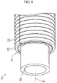
- the intermediate layer 14 is compressed between the inner wall 24A and the pipe body 12, so that the compressively held portion 14A is in tight contact with the covering layer 20, and a projection portion 14B is engaged between the side walls 24B of the adjacent groove portions 24, and the intermediate layer may be easily shortened together with the covering layer 20. Owing to such a configuration, an end of the pipe body 12 can be exposed as depicted in FIG. 8 .
- the thickness H1 of the outer walls 22A is set to be less than the thickness H2 of the inner walls 24A in the embodiment, the thickness H1 may be the same as the thickness H2.
- outer walls 22A has a substantially straight shape in the axial direction S in the embodiment, the outer walls may have an arc shape swelling outward in the radial direction.
- the inner walls 24A may also have an arc shape swelling inward in the radial direction.
- the intermediate layer 14 is entirely in contact with the outer circumferential surface of the pipe body 12.
- the intermediate layer 14 is compressed between the inner wall 24A and the pipe body 12.
- the compressively held portion 14A is brought into tight contact with the covering layer 20, and the projection portion 14B is engaged between the side walls 24B of the adjacent groove portions 24. Therefore the intermediate layer 14 may easily follow the movement of the covering layer 20, and remaining of the intermediate layer 14 on the outer circumferential surface of the pipe body 12 is inhibited, so that the intermediate layer can be easily shortened with the covering layer 20.
- another layer 13 may be disposed between the intermediate layer 14 and the pipe body 12.
- a low friction sheet may be provided to improve the sliding property between the intermediate layer 14 and the pipe body 12 to establish a configuration that the intermediate layer 14 and such other layer 13 can follow the covering layer 20 and the covering layer can easily deform, when an end of the pipe body 12 is to be exposed by shortening and deforming of the covering layer 20.
- a mode without an intermediate layer 14 is also possible, and for example it may be a composite pipe constituted solely with a pipe body 12 and a covering layer 20.
- a method of manufacturing the composite pipe 10 of the present embodiment is described.
- a method of manufacturing a composite pipe 10 having a pipe body 12, an intermediate layer 14, and a covering layer 20 is described.
- a manufacturing apparatus 30 illustrated in Figure 4 can be used for manufacturing the composite pipe 10.
- the manufacturing apparatus 30 includes an extruder 32, a die 34, a corrugation mold 36, a cooling tank 38, and a receiving apparatus 39.
- the right section in Figure 4 is defined as being upstream in the manufacturing flow of the composite pipe 10 in the manufacturing apparatus 30, and the composite pipe is manufactured with the pipe body 12 being transferred from the right to the left.
- the transferring direction is referred to as "manufacturing direction Y".
- the die 34, the corrugation mold 36, the cooling tank 38, and the receiving apparatus 39 are disposed in the listed order in the manufacturing direction Y, and the extruder 32 is disposed upstream relative to the die 34.
- a pipe body 12 wound up in a coil shape, and a sheet-shaped member 14S, which is a sheet to form an intermediate layer 14 (for example, porous resin sheet) wound up in a roll shape, are disposed upstream of the die 34.
- the pipe body 12 in a coil shape and the sheet-shaped member 14S in a roll shape are pulled by the receiving apparatus 39 in the manufacturing direction Y, and thus continuously extracted.
- the sheet-shaped member 14S is wound around the entire outer circumferential of the pipe body 12 extracted continuously, before the die 34.
- the sheet-shaped member 14S is slackened before the die 34 in order not to allow a tensile force to act, and is inserted into the die 34.
- the outer circumferential surface of the sheet-shaped member 14S wound onto the outer circumferential surface of the pipe body 12 is applied with a molten resin material (a molten product of a resin composition for forming a covering layer 20) cylindrically extruded from the die 34, and a resin layer 20A is formed.
- a molten resin material a molten product of a resin composition for forming a covering layer 20
- the resin material can easily enter the pores (foams) in the porous resin sheet, so that the adhesion between the sheet-shaped member 14S and the resin layer 20A is improved.
- a corrugation step (step of formation of a bellows shape) is performed in the corrugation mold 36 disposed downstream relative to the die 34.
- the corrugation mold 36 corresponds to, for example, a pair of molds, and all the molds have a semi-arc inner surface.
- Each annular cavity 36A is formed on a portion of the inner circumferential surface of such a mold, corresponding to the ridge portions 22 of the covering layer 20, and each annular inner projection 36B is formed on a portion thereof, corresponding to the groove portions 24, and has a bellows shape.
- Each vent 36C is formed in such a cavity 36A, the vent being formed with having one end in communication with such a cavity 36A and penetrating through each of such corrugation molds 36. Suction in such a cavity 36A is performed from the outside of each of such corrugation molds 36 via the vent 36C.
- Such a pair of corrugation molds 36 approaches to the resin layer 20A from two directions downstream relative to the die 34 and the inner surfaces thereof are brought into contact therewith, and the corrugation molds are transferred together with the pipe body 12 in the manufacturing direction Y with the outer circumferential surface of the tubular extruded product 21 being covered under pushing of the resin layer 20A by the inner projection 36B. Suction from the outside of the corrugation molds 36 is here performed to thereby impart a negative pressure in the cavity 36A. Thus, the resin layer 20A is transferred outward in the radial direction, and a bellows-shaped covering layer 20 along with each of the corrugation molds 36 is formed.
- the MFR of the covering layer 20 is preferably 0.8 or less.
- the fluidity of the molten product of a resin composition for forming a covering layer 20 is adjusted to an appropriate range, and it is inhibited that the molten product flows into a contact portion between a pair of corrugation molds 36 so that generation of burr radially outside the covering layer 20 is suppressed.
- the sheet-shaped member 15S enters the cavity 36A in the protrusion space 23 corresponding to the ridge portions 22 of the covering layer 20, and the projection portions 14B is formed.
- a portion corresponding to the inner walls 24A of the groove portions 24 of the covering layer 20 is not only kept with adhering to the covering layer 20, but also compressed between the pipe body 12 and the inner walls 24A, and the compressively held portion 14A is formed.
- the covering layer 20 is cooled in a cooling tank 38.
- the composite pipe 10 is manufactured.
- the present disclosure provides the following composite pipe.
- a manufacturing apparatus having the structure shown in FIG. 4 was prepared.
- a polybutene pipe wound in a form of a coil was loaded as the pipe body 12, and a polyurethane foam sheet A produced by the method described later was loaded as the sheet-shaped member 14S.
- the receiving apparatus 39 was operated to continuously draw out the coiled polybutene pipe and the rolled-up polyurethane foam sheet A, and the polyurethane foam sheet A was wound around the entire outer circumferential surface of the polybutene pipe.
- the polyurethane foam sheet A was slackened before a die 34 and then inserted into the die 34.
- a molten resin material (low density polyethylene (LDPE), density 920 kg/m 3 , MFR 0.35) was cylindrically extruded from the die 34 and applied to the outer circumferential surface of the polyurethane foam sheet A to form a resin layer.
- LDPE low density polyethylene
- the corrugation molds 36 are a pair of molds with the same inner surface shape, both of which have a semi-arc inner surface.
- an annular cavity 36A is formed at a part corresponding to each ridge portion of the covering layer to be formed, and an annular inward projection 36B at a part corresponding to each groove portion is formed, such that a bellows shape is formed.
- a vent 36C one end of which is in communication with the cavity 36A through the corrugation mold 36, is formed.
- the resin layer 20A was moved together with the polybutene pipe in a manufacturing direction Y, while the resin layer 20A was pressed by the inward projections 36B, and the inside of cavity 36A was aspirated from the outside of the corrugation mold 36 to a negative pressure.
- the bellows covering layer was formed along the corrugation mold 36.
- the length L1 in the axial direction S of the ridge portion 22 of the covering layer was 2.1 mm, and the length L2 in the axial direction S of the groove portion 24 was 1.5 mm.
- the thickness of the covering layer was 0.2 mm at the thinnest portion and 0.5 mm at the thickest portion.
- the difference in radius ⁇ R between the outer surfaces of the ridge portion 22 and the groove portion 24 was 88.9%.
- the distance between the inner surface of the groove portion 24 of the covering layer and the outer surface of the polybutene pipe (the pipe body), namely the difference between the outer circumferential surface of the pipe body and the radially inner surface of the inner wall 24A of the covering layer (clearance at the compressively held portion) was 1.5 mm.
- the diameter of the covering layer (the average value of the diameters of the outer surfaces of the ridge portions 22) was 23.5 mm.
- the polyurethane foam sheet A (intermediate layer) was entirely in contact with the outer surface of the pipe body.
- a polyisocyanate and a polyol as raw materials were mixed and reacted together with a catalyst, a foaming agent, and a foam stabilizer, and the product was cut to a desired thickness with a cutting machine to yield a polyurethane foam sheet A having a thickness (average thickness in a natural state) of 2.5 mm.
- a composite pipe was obtained in the same manner as Example 1, except that the resin material used for forming the covering layer was changed to polyethylene (density 920 kg/m 3 , MFR 1.2).
- a composite pipe was obtained in the same manner as Example 1, except that the resin material used for forming the covering layer was changed to polyethylene (density 922 kg/m 3 , MFR 0.5).
- a composite pipe was obtained in the same manner as Example 1, except that the resin material used for forming the covering layer was changed to polyethylene (density 957 kg/m 3 , MFR 0.3).
- a composite pipe was obtained in the same manner as Example 1, except that the resin material used for forming the covering layer was changed to polyethylene (density 959 kg/m 3 , MFR 0.27).
- a composite pipe was obtained in the same manner as Example 1, except that the resin material used for forming the covering layer was changed to polyethylene (density 956 kg/m 3 , MFR 0.14).
- a test in which an axial end of a composite pipe was grasped by hand from the outside of the covering layer and the covering layer was shortened in the axial direction of the pipe body by pressing the other end of the composite pipe against a flat surface to expose the internal pipe body, was conducted and evaluated whether the shortening of the covering layer can be carried out easily or not.
- burr was generated radially outside a covering layer in producing a composite pipe due to penetration of a resin material for forming a covering layer into a contact portion between a pair of corrugation molds was visually examined. The results are shown in Table 1 below. Yes: Burr was recognized. No: Burr was not recognized at all.
- Example 2 In Example 2 in which the MFR of the covering layer exceeded 0.8, generation of burr was recognized, on the contrary in Examples 1 and 3 with the MFR of 0.8 or less, generation of burr was not recognized.
- HDPE high density polyethylene
- LDPE low density polyethylene
- a composite pipe was obtained in the same manner as in Example 1 except that the resin material used for forming a covering layer in Example 1 was changed to a mixed material having mixed the high density polyethylene (HDPE) and the low density polyethylene (LDPE) at the mass ratio set forth in Table 2 below.
- the density of the covering layer of each composite pipe obtained was a value shown in Table 2 below.
Landscapes
- Engineering & Computer Science (AREA)
- General Engineering & Computer Science (AREA)
- Mechanical Engineering (AREA)
- Architecture (AREA)
- Civil Engineering (AREA)
- Structural Engineering (AREA)
- Rigid Pipes And Flexible Pipes (AREA)
- Laminated Bodies (AREA)
Applications Claiming Priority (2)
| Application Number | Priority Date | Filing Date | Title |
|---|---|---|---|
| JP2016251954 | 2016-12-26 | ||
| PCT/JP2017/045833 WO2018123779A1 (ja) | 2016-12-26 | 2017-12-20 | 複合管 |
Publications (2)
| Publication Number | Publication Date |
|---|---|
| EP3575657A1 true EP3575657A1 (de) | 2019-12-04 |
| EP3575657A4 EP3575657A4 (de) | 2020-03-11 |
Family
ID=62710499
Family Applications (1)
| Application Number | Title | Priority Date | Filing Date |
|---|---|---|---|
| EP17887630.6A Withdrawn EP3575657A4 (de) | 2016-12-26 | 2017-12-20 | Verbundrohr |
Country Status (5)
| Country | Link |
|---|---|
| EP (1) | EP3575657A4 (de) |
| JP (1) | JP7063821B2 (de) |
| CN (1) | CN110114602A (de) |
| TW (1) | TW201829164A (de) |
| WO (1) | WO2018123779A1 (de) |
Families Citing this family (2)
| Publication number | Priority date | Publication date | Assignee | Title |
|---|---|---|---|---|
| JP7474585B2 (ja) * | 2019-11-26 | 2024-04-25 | 日鉄建材株式会社 | 繰出し式排水パイプ、地盤排水構造、及び繰出し式排水パイプの貫入方法 |
| JP7133596B2 (ja) * | 2020-09-10 | 2022-09-08 | 住友電装株式会社 | グロメット |
Family Cites Families (19)
| Publication number | Priority date | Publication date | Assignee | Title |
|---|---|---|---|---|
| JPH0257790A (ja) * | 1988-08-18 | 1990-02-27 | Toyo Densen Kk | 断熱管及びその製造方法 |
| DE4128654C2 (de) * | 1991-08-29 | 1995-05-18 | Wolfgang Mayer | Mehrschichtiges Leitungsrohr aus Kunststoff und Verfahren zu dessen Herstellung |
| RU2142092C1 (ru) * | 1995-04-03 | 1999-11-27 | Упонор Б.В. | Способ изготовления рифленых труб и рифленые трубы, изготовленные этим способом |
| GB2311114B (en) * | 1996-03-15 | 1999-04-28 | T & N Technology Ltd | Convoluted flexible protective sleeves |
| JP4557388B2 (ja) * | 2000-07-18 | 2010-10-06 | 因幡電機産業株式会社 | 保護管付き流体輸送管の製造方法 |
| JP4516680B2 (ja) * | 2000-09-28 | 2010-08-04 | 株式会社パイオラックス | コルゲートチューブ |
| JP4190923B2 (ja) * | 2002-05-24 | 2008-12-03 | 古河電気工業株式会社 | 伸縮波付けさや管と給水・給湯用配管材の配管構造 |
| AU2003280235A1 (en) * | 2002-10-31 | 2004-05-25 | Plastiflex Belgium | Tubular body having isolation layer of foamed plastic and method for producing same |
| JP4201638B2 (ja) * | 2003-04-28 | 2008-12-24 | 株式会社三洋化成 | コルゲート管の製造方法およびこの製造方法により製造されたコルゲート管 |
| JP2007139043A (ja) * | 2005-11-17 | 2007-06-07 | Aron Kasei Co Ltd | コルゲート二重管 |
| JP3168436U (ja) * | 2011-04-01 | 2011-06-09 | 株式会社極美全掃 | 高圧ホース |
| US9297491B2 (en) * | 2012-02-08 | 2016-03-29 | Federal-Mogul Powertrain, Inc. | Thermally resistant convoluted sleeve and method of construction thereof |
| JP2013231490A (ja) * | 2012-05-01 | 2013-11-14 | Bridgestone Corp | 複合管、及び複合管の製造方法 |
| JP5775541B2 (ja) * | 2013-03-08 | 2015-09-09 | 株式会社ブリヂストン | 複合管 |
| JP2015048909A (ja) | 2013-09-02 | 2015-03-16 | 未来工業株式会社 | 配線・配管材用の波付管 |
| JP6263431B2 (ja) * | 2014-04-07 | 2018-01-17 | 株式会社クレハ | 喰い切り支持部を備える合成樹脂製ブロー成形多層容器 |
| JP6391519B2 (ja) * | 2015-03-30 | 2018-09-19 | 三井・デュポンポリケミカル株式会社 | ヒートシール用組成物及び積層体 |
| EP3470719B1 (de) * | 2016-06-09 | 2021-10-13 | Bridgestone Corporation | Verbundrohr |
| EP3561355A4 (de) * | 2016-12-26 | 2019-12-18 | Bridgestone Corporation | Verbundrohr und verfahren für die herstellung des verbundrohrs |
-
2017
- 2017-12-20 WO PCT/JP2017/045833 patent/WO2018123779A1/ja not_active Ceased
- 2017-12-20 JP JP2018559107A patent/JP7063821B2/ja active Active
- 2017-12-20 CN CN201780080577.XA patent/CN110114602A/zh active Pending
- 2017-12-20 EP EP17887630.6A patent/EP3575657A4/de not_active Withdrawn
- 2017-12-21 TW TW106145131A patent/TW201829164A/zh unknown
Also Published As
| Publication number | Publication date |
|---|---|
| WO2018123779A1 (ja) | 2018-07-05 |
| JPWO2018123779A1 (ja) | 2019-11-07 |
| CN110114602A (zh) | 2019-08-09 |
| EP3575657A4 (de) | 2020-03-11 |
| JP7063821B2 (ja) | 2022-05-09 |
| TW201829164A (zh) | 2018-08-16 |
Similar Documents
| Publication | Publication Date | Title |
|---|---|---|
| EP3470719B1 (de) | Verbundrohr | |
| EP2261004B1 (de) | Rohr für Temperaturregelungssysteme und Verfahren zur Herstellung | |
| EP2719721B1 (de) | Formkörper aus polyolefinbasierten expandierten Perlen | |
| US8435615B2 (en) | Hollow foamed blow-molded article | |
| EP3561356A1 (de) | Verbundrohr | |
| CN102821930B (zh) | 聚丙烯系树脂发泡吹塑成形体的制造方法 | |
| EP2246175B1 (de) | Geschäumter, blasgeformter Gegenstand aus Kunststoff auf Polyethylenbasis | |
| EP1749635B1 (de) | Geformter Schaumhohlkörper und Verfahren zu deren Herstellung | |
| WO2018123886A1 (ja) | 複合管及び複合管の製造方法 | |
| MX2014008877A (es) | Metodo para producir un articulo de espuma moldeada y articulo de espuma moldeada. | |
| JP2015000547A (ja) | ダクト | |
| JP7063821B2 (ja) | 複合管 | |
| EP3561357A1 (de) | Verbundrohr | |
| US12194708B2 (en) | Thermally insulated pipe | |
| US8343413B2 (en) | Method for manufacturing molded foam | |
| US6896235B2 (en) | Mold for molding foamed tube for tire, and method of manufacturing foamed tube for tire | |
| EP4079797B1 (de) | Mehrschichtige expandierte kügelchen und formartikel daraus | |
| JP6657549B2 (ja) | 二重構造ダクトの製造方法 | |
| JP4771518B2 (ja) | 発泡中空成形体の製造方法 | |
| TW202103911A (zh) | 複合管及複合管之製造方法 | |
| JP2023142260A (ja) | 複合管 | |
| EP4711405A1 (de) | Geschäumte polypropylenharzpartikel und verfahren zur herstellung davon | |
| JP5148263B2 (ja) | 発泡ゴム積層体の製造方法 | |
| JP2007203725A (ja) | 円形樹脂管ジョイント並びにその製造方法 | |
| JP2005125510A (ja) | マンドレルおよびその製造方法 |
Legal Events
| Date | Code | Title | Description |
|---|---|---|---|
| PUAI | Public reference made under article 153(3) epc to a published international application that has entered the european phase |
Free format text: ORIGINAL CODE: 0009012 |
|
| 17P | Request for examination filed |
Effective date: 20190628 |
|
| AK | Designated contracting states |
Kind code of ref document: A1 Designated state(s): AL AT BE BG CH CY CZ DE DK EE ES FI FR GB GR HR HU IE IS IT LI LT LU LV MC MK MT NL NO PL PT RO RS SE SI SK SM TR |
|
| AX | Request for extension of the european patent |
Extension state: BA ME |
|
| A4 | Supplementary search report drawn up and despatched |
Effective date: 20200211 |
|
| RIC1 | Information provided on ipc code assigned before grant |
Ipc: B32B 1/08 20060101ALI20200205BHEP Ipc: F16L 11/11 20060101AFI20200205BHEP Ipc: H02G 3/04 20060101ALI20200205BHEP |
|
| DAV | Request for validation of the european patent (deleted) | ||
| DAX | Request for extension of the european patent (deleted) | ||
| STAA | Information on the status of an ep patent application or granted ep patent |
Free format text: STATUS: THE APPLICATION IS DEEMED TO BE WITHDRAWN |
|
| 18D | Application deemed to be withdrawn |
Effective date: 20200910 |