EP3575724B1 - Wärmetauscher und wärmepumpenwassererhitzer - Google Patents
Wärmetauscher und wärmepumpenwassererhitzer Download PDFInfo
- Publication number
- EP3575724B1 EP3575724B1 EP17894252.0A EP17894252A EP3575724B1 EP 3575724 B1 EP3575724 B1 EP 3575724B1 EP 17894252 A EP17894252 A EP 17894252A EP 3575724 B1 EP3575724 B1 EP 3575724B1
- Authority
- EP
- European Patent Office
- Prior art keywords
- pipe
- heat exchanger
- resin
- refrigerant
- heat
- Prior art date
- Legal status (The legal status is an assumption and is not a legal conclusion. Google has not performed a legal analysis and makes no representation as to the accuracy of the status listed.)
- Active
Links
Images




Classifications
-
- F—MECHANICAL ENGINEERING; LIGHTING; HEATING; WEAPONS; BLASTING
- F28—HEAT EXCHANGE IN GENERAL
- F28D—HEAT-EXCHANGE APPARATUS, NOT PROVIDED FOR IN ANOTHER SUBCLASS, IN WHICH THE HEAT-EXCHANGE MEDIA DO NOT COME INTO DIRECT CONTACT
- F28D7/00—Heat-exchange apparatus having stationary tubular conduit assemblies for both heat-exchange media, the media being in contact with different sides of a conduit wall
- F28D7/10—Heat-exchange apparatus having stationary tubular conduit assemblies for both heat-exchange media, the media being in contact with different sides of a conduit wall the conduits being arranged one within the other, e.g. concentrically
- F28D7/14—Heat-exchange apparatus having stationary tubular conduit assemblies for both heat-exchange media, the media being in contact with different sides of a conduit wall the conduits being arranged one within the other, e.g. concentrically both tubes being bent
-
- F—MECHANICAL ENGINEERING; LIGHTING; HEATING; WEAPONS; BLASTING
- F28—HEAT EXCHANGE IN GENERAL
- F28D—HEAT-EXCHANGE APPARATUS, NOT PROVIDED FOR IN ANOTHER SUBCLASS, IN WHICH THE HEAT-EXCHANGE MEDIA DO NOT COME INTO DIRECT CONTACT
- F28D7/00—Heat-exchange apparatus having stationary tubular conduit assemblies for both heat-exchange media, the media being in contact with different sides of a conduit wall
- F28D7/10—Heat-exchange apparatus having stationary tubular conduit assemblies for both heat-exchange media, the media being in contact with different sides of a conduit wall the conduits being arranged one within the other, e.g. concentrically
- F28D7/106—Heat-exchange apparatus having stationary tubular conduit assemblies for both heat-exchange media, the media being in contact with different sides of a conduit wall the conduits being arranged one within the other, e.g. concentrically consisting of two coaxial conduits or modules of two coaxial conduits
-
- F—MECHANICAL ENGINEERING; LIGHTING; HEATING; WEAPONS; BLASTING
- F28—HEAT EXCHANGE IN GENERAL
- F28F—DETAILS OF HEAT-EXCHANGE AND HEAT-TRANSFER APPARATUS, OF GENERAL APPLICATION
- F28F21/00—Constructions of heat-exchange apparatus characterised by the selection of particular materials
- F28F21/06—Constructions of heat-exchange apparatus characterised by the selection of particular materials of plastics material
- F28F21/062—Constructions of heat-exchange apparatus characterised by the selection of particular materials of plastics material the heat-exchange apparatus employing tubular conduits
-
- F—MECHANICAL ENGINEERING; LIGHTING; HEATING; WEAPONS; BLASTING
- F28—HEAT EXCHANGE IN GENERAL
- F28F—DETAILS OF HEAT-EXCHANGE AND HEAT-TRANSFER APPARATUS, OF GENERAL APPLICATION
- F28F21/00—Constructions of heat-exchange apparatus characterised by the selection of particular materials
- F28F21/08—Constructions of heat-exchange apparatus characterised by the selection of particular materials of metal
- F28F21/081—Heat exchange elements made from metals or metal alloys
-
- F—MECHANICAL ENGINEERING; LIGHTING; HEATING; WEAPONS; BLASTING
- F28—HEAT EXCHANGE IN GENERAL
- F28D—HEAT-EXCHANGE APPARATUS, NOT PROVIDED FOR IN ANOTHER SUBCLASS, IN WHICH THE HEAT-EXCHANGE MEDIA DO NOT COME INTO DIRECT CONTACT
- F28D21/00—Heat-exchange apparatus not covered by any of the groups F28D1/00 - F28D20/00
- F28D2021/0019—Other heat exchangers for particular applications; Heat exchange systems not otherwise provided for
- F28D2021/0068—Other heat exchangers for particular applications; Heat exchange systems not otherwise provided for for refrigerant cycles
-
- F—MECHANICAL ENGINEERING; LIGHTING; HEATING; WEAPONS; BLASTING
- F28—HEAT EXCHANGE IN GENERAL
- F28F—DETAILS OF HEAT-EXCHANGE AND HEAT-TRANSFER APPARATUS, OF GENERAL APPLICATION
- F28F1/00—Tubular elements; Assemblies of tubular elements
- F28F1/10—Tubular elements and assemblies thereof with means for increasing heat-transfer area, e.g. with fins, with projections, with recesses
- F28F1/12—Tubular elements and assemblies thereof with means for increasing heat-transfer area, e.g. with fins, with projections, with recesses the means being only outside the tubular element
- F28F1/14—Tubular elements and assemblies thereof with means for increasing heat-transfer area, e.g. with fins, with projections, with recesses the means being only outside the tubular element and extending longitudinally
- F28F1/20—Tubular elements and assemblies thereof with means for increasing heat-transfer area, e.g. with fins, with projections, with recesses the means being only outside the tubular element and extending longitudinally the means being attachable to the element
-
- F—MECHANICAL ENGINEERING; LIGHTING; HEATING; WEAPONS; BLASTING
- F28—HEAT EXCHANGE IN GENERAL
- F28F—DETAILS OF HEAT-EXCHANGE AND HEAT-TRANSFER APPARATUS, OF GENERAL APPLICATION
- F28F2225/00—Reinforcing means
- F28F2225/04—Reinforcing means for conduits
-
- F—MECHANICAL ENGINEERING; LIGHTING; HEATING; WEAPONS; BLASTING
- F28—HEAT EXCHANGE IN GENERAL
- F28F—DETAILS OF HEAT-EXCHANGE AND HEAT-TRANSFER APPARATUS, OF GENERAL APPLICATION
- F28F2240/00—Spacing means
Definitions
- the present invention relates to a double-pipe heat exchanger including a first pipe and a second pipe provided in the first pipe, and a heat pump water heater including the heat exchanger.
- Double-pipe heat exchangers each including a first pipe and a second pipe provided in the first pipe have been known.
- water is made to flow through the first pipe
- refrigerant is made to flow through the second pipe
- the water and the refrigerant can be made to exchange heat with each other.
- heat exchanger including: a water flow passage which allows water to flow therethrough; and a refrigerant flow passage which is provided in the water flow passage, and allows refrigerant to flow through the refrigerant flow passage, the heat exchanger causing heat exchange to be performed between the water and the refrigerant, wherein a wall for the water flow passage is made of a transparent resin material, whereby in an appearance of the heat exchanger, a refrigerant pipe forming the water flow passage is visible from the wall for the water flow passage" (see, for example, Patent Literature 1).
- a first pipe is formed of a transparent resin material, whereby the inside of the first pipe is visible. Therefore, in the heat exchanger disclosed in Patent Literature 1, a second pipe provided in a first pipe can be confirmed from the outside of the heat exchanger, thus improving serviceability.
- Another heat exchanger is disclosed in document JP-S-6422173U comprising all the features of the preamble.
- Patent Literature 1 Japanese Unexamined Patent Application Publication No. 2013-011387
- the first pipe is made of a transparent resin material in order to improve serviceability.
- this Literature does not consider that the first pipe is deformed. That is, the double-pipe heat exchanger including the first pipe formed of resin need to be further modified in order to improve their reliability.
- the present invention has been made in view of the above circumstances, and an object of the invention is to provide a heat exchanger and a heat pump water heater, which are both capable of preventing a first pipe formed of resin and a second pipe formed of metal from contacting each other without applying a complexed structure.
- the heat exchanger includes: a first pipe which is formed of resin, and allows fluid to flow through the first pipe; a second pipe which is formed of metal, provided in the first pipe, and allows refrigerant to flow through the second pipe; and a resin element which is formed as an element separate from the first pipe and the second pipe, and provided in a region in space between an inner surface of the first pipe and an outer surface of the second pipe, wherein the first pipe and the second pipe include respective bent portions ,wherein the resin element is provided at least between a refrigerant inlet provided at an end of the second pipe and a position which is separated from the refrigerant inlet by 5% of an entire length of the second pipe, and wherein the resin element is provided only on an outer peripheral side of the bent portion of the second pipe.
- a heat pump water heater includes the above heat exchanger as a condenser.
- the resin element formed as an element separate from the first pipe and the second pipe is provided in a region in space between an inner surface of the first pipe and an outer surface of the second pipe. Because of this configuration, it is possible to prevent contact between the first pipe and the second pipe without applying a complexed structure.
- the heat pump water heater according to the other embodiment of the present invention includes the above exchanger.
- the resin element because of provision of the resin element, it is possible to prevent contact between the first pipe and the second pipe, thereby reducing deformation of the first pipe, and thus improving the reliability.
- Fig. 1 is a refrigerant circuit diagram schematically illustrating an example of a circuit configuration of a heat pump water heater 100 according to an embodiment of the present invention.
- the heat pump water heater 100 will be described with reference to Fig. 1 .
- the heat pump water heater 100 includes a refrigerant circuit A and a fluid circuit B.
- the fluid circuit B is connected to at least one of various load-side devices in each of which hot water is used, such as a household tap and a bath, and configured to supply hot water to the load-side apparatus.
- the fluid circuit B is also connected to a water-supply pipe (not illustrated) such as a water pipe, and configured to supply water through the water-supply pipe.
- refrigerant circulates through a refrigerant pipe 20A.
- refrigerant for example, carbon dioxide can be used.
- the refrigerant circuit A is provided with a compressor 101 which compresses the refrigerant, a first heat exchanger 50 serving as a condenser (gas cooler), an expansion device 102 and a second heat exchanger 103 serving as an evaporator.
- the compressor 101 compresses the refrigerant.
- the refrigerant compressed by the compressor 101 is discharged from the compressor 101, and sent into the first heat exchanger 50.
- the compressor 101 for example, a rotary compressor, a scroll compressor, a screw compressor or a reciprocating compressor can be used.
- the first heat exchanger 50 serves as a condenser, and causes heat exchange to be performed between high-temperature and high-pressure refrigerant which flows through the refrigerant circuit A and fluid which flows through the fluid circuit B, to thereby condense the refrigerant.
- the first heat exchanger 50 is a double-pipe heat exchanger which includes a first pipe 10 and a second pipe 20 provided in the first pipe 10.
- the first pipe 10 allows the fluid such as water to flow therethrough.
- the second pipe 20 allows the refrigerant to flow therethrough.
- the first heat exchanger 50 corresponds to "heat exchanger" of the present invention.
- the expansion device 102 expands the refrigerant having flowed out of the first heat exchanger 50 to reduce the pressure of the refrigerant. It is appropriate that as the expansion device 102, for example, an electric expansion valve capable of adjusting the flow rate of refrigerant is used. Besides the electric expansion valve, for example, a mechanical expansion valve using a diaphragm as a pressure-receiving portion or a capillary tube can be used as the expansion device 102.
- the second heat exchanger 103 serves as an evaporator, and cause heat exchange to be performed between low-temperature and low-pressure refrigerant having flowed out of the expansion device 102 and air sent by a fan 105, to thereby evaporate the low-temperature and low-pressure liquid refrigerant or two-phase refrigerant.
- a fin-and-tube heat exchanger for example, a fin-and-tube heat exchanger, a microchannel heat exchanger, a shell-and-tube heat exchanger, a heat pipe heat exchanger, a double-pipe heat exchanger or a plate heat exchanger can be used.
- Fig. 1 illustrates by way of example the case where the second heat exchanger 103 is a fin-and-tube heat exchanger which causes heat exchange to be performed between air and refrigerant.
- the fluid circuit B the fluid circulates through the fluid pipe 10A.
- the fluid for example, water or antifreeze can be adopted.
- the fluid circuit B includes the first heat exchanger 50 and a pump (not illustrated) which transfers the fluid.
- the heat pump water heater 100 further includes a controller 60 which exerts a centralized control of the entire heat pump water heater 100.
- the controller 60 controls the driving frequency of the compressor 101 in accordance with a required water heating capacity.
- the controller 60 further controls the opening degree of the expansion device 102 in accordance with operation conditions.
- the controller 60 also controls driving of the fan 105 and the pump (not illustrated) in accordance with the operation conditions.
- the controller 60 controls each of actuators (including the compressor 101, the expansion device 102, the fan 105 and the pump not illustrated) in response to a user's instructions and based on information sent from temperature sensors (not illustrated) and pressure sensors (not illustrated). It should be noted that the controller 60 may be included in a unit incorporating the compressor 101 or may be included in another unit.
- Each of function portions included in the controller 60 is dedicated hardware or a micro processing unit (MPU) which executes a program stored in a memory.
- MPU micro processing unit
- the heat pump water heater 100 is capable of supplying hot water in response to an instruction from a load-side device.
- each actuator is controlled by the controller 60.
- the low-temperature and low-pressure refrigerant is compressed by the compressor 101 to change into high-temperature and high-pressure gas refrigerant.
- the high-temperature and high-pressure gas refrigerant is discharged from the compressor 101, and flows into the first heat exchanger 50.
- the refrigerant having flowed into the first heat exchanger 50 passes through the second pipe 20 which forms part of the refrigerant circuit A, and exchanges heat with the fluid flowing through the first pipe 10 which forms part of the fluid circuit B. At this time, the refrigerant is condensed to change into low-temperature and high-pressure liquid refrigerant, and then flows out of the first heat exchanger 50.
- carbon dioxide is used as the refrigerant
- the refrigerant changes in temperature while remaining in a supercritical state.
- the fluid having flowed into the first pipe 10 is heated by the refrigerant flowing through the second pipe 20, and then supplied to the load-side device.
- the low-temperature and high-pressure liquid refrigerant having flowed out of the first heat exchanger 50 is changed into low-temperature and low-pressure liquid refrigerant (or two-phase refrigerant) by the expansion device 102.
- the low-temperature and low-pressure liquid refrigerant (or two-phase refrigerant) flows into the second heat exchanger 103, then exchanges heat with air sent by the fan 105 provided close to the second heat exchanger 103 to change into low-temperature and low-pressure gas refrigerant, and flows out of the second heat exchanger 103.
- the refrigerant having flowed out of the second heat exchanger 103 is re-sucked into the compressor 101.
- Fig. 1 illustrates the case where in the refrigerant circuit A, the refrigerant flows in a constant direction.
- a flow-passage switching device may be provided on a discharge side of the compressor 101 such that the flow of refrigerant can be reversed.
- the first heat exchanger 50 also serves as an evaporator
- the second heat exchanger 103 also serves as a condenser.
- the flow-passage switching device a combination of two-way valves, a combination of three-way valves or a four-way valve can be adopted.
- the refrigerant for use in the heat pump water heater 100 carbon dioxide be used; however, the refrigerant for use in the heat pump water heater 100 is not limited to carbon dioxide.
- carbon dioxide for example, natural refrigerant (for example, carbon hydride or helium), chlorine-based substitute refrigerant (for example, HFC410A, HFC407C or HFC404A) or fluorocarbon-based refrigerant (for example R22 or R134a) for use in existing products may be used.
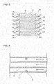
- Fig. 2 is a perspective view schematically illustrating an appearance of the first heat exchanger 50.
- Fig. 3 is a transparent perspective view schematically illustrating an internal configuration of the first heat exchanger 50.
- Fig. 4 is a schematic view schematically illustrating an example of a sectional configuration of the first heat exchanger 50.
- Fig. 5 is a schematic view schematically illustrating an example of a configuration of the first heat exchanger 50.
- the first heat exchanger 50 includes the first pipe 10 which allows fluid to flow through the first pipe 10 and the second pipe 20 which allows refrigerant to flow through the second pipe 20.
- the second pipe 20 is provided in the first pipe 10. That is, the first heat exchanger 50 is a double-pipe heat exchanger as described above.
- the first pipe 10 is connected to the fluid pipe 10A, and forms along with the fluid pipe 10A part of the fluid circuit B.
- the second pipe 20 is connected to the refrigerant pipe 20A, and forms along with the refrigerant pipe 20A part of the refrigerant circuit A.
- bent portions of the first pipe 10 are denoted by 10X
- bent portions of the second pipe 20 are denoted by 20X; and each of the bent portions of the second pipe 20 will thus be referred to as bent portion 10X, and each of the bent portions of the second pipe 20 will thus be referred to as bent portion 20X.
- the first pipe 10 and the second pipe 20 may be bent a number of times such that turns of these pipes are stacked together as illustrated in Figs. 2 and 3 . That is, the first heat exchanger 50 may be configured to have such an appearance that the turns of the first pipe 10 are stacked in a direction from lower part of each of Figs. 2 and 3 toward upper part of each of these figures.
- the first pipe 10 and the second pipe 20 may be bent a number of times to extend toward the center as illustrated in Fig. 4 ; that is, the first heat exchanger 50 can be configured to have such an appearance that the first pipe 10 is turned a number of times to extend from outer part of Fig. 4 toward inner part thereof.
- the first pipe 10 and the second pipe 20 may be bent a number of times in a zigzag manner as illustrated in Fig. 5 . That is, the first heat exchanger can be configured to have such an appearance that the first pipe 10 is turned in a zigzag manner and turns of the first pipes are stacked in a direction from lower part of Fig.5 toward upper part of Fig. 5 .
- a fluid inlet 10a and a fluid outlet 10b are provided at ends of the first pipe 10.
- the fluid inlet 10a allows the fluid to flow into the first pipe 10 through the fluid inlet 10a
- the fluid outlet 10b allows the fluid to flow out of the first pipe 10 through the fluid outlet 10b.
- the first pipe 10 is made of a resin material. The resin material for the first pipe 10 will be described in detail later.
- a refrigerant inlet 20a and a refrigerant outlet 20b are provided at respective ends of the second pipe 20.
- the refrigerant inlet 20a allows the refrigerant to flow into the second pipe 20 through the refrigerant inlet 20a
- the refrigerant outlet 20b allows the refrigerant to flow out of the second pipe 20 through the refrigerant outlet 20b.
- the second pipe 20 is made of a metal material such as copper or aluminum.
- Figs. 2 to 5 each illustrates by way of example the case where the fluid inlet 10a and the refrigerant inlet 20a are paired with each other, and the fluid outlet 10b and the refrigerant outlet 20b are paired with each other, whereby the fluid and the refrigerant flow in parallel to each other.
- the fluid inlet 10a and the refrigerant outlet 20b may be paired with each other, and the fluid outlet 10b and the refrigerant inlet 20a may be paired with each other, whereby the fluid and the refrigerant flow in opposite directions.
- the first heat exchanger 50 serves as a condenser, high-temperature refrigerant flows through the second pipe 20. If an outer surface of the second pipe 20 contacts an inner surface of the first pipe 10, the first pipe 10 may be deformed since it is made of resin. In view of this point, the first heat exchanger 50 is provided with resin elements 30.
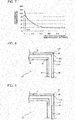
- Fig. 6 is an enlarged vertical-sectional view schematically illustrating an example of a sectional configuration of part of the first heat exchanger 50.
- Fig. 7 is a graph indicating a refrigerant temperature distribution of the first heat exchanger 50. With references to Figs. 6 and 7 , preferred positions of the resin element 30 will be described. In Fig. 7 , the vertical axis represents the temperature of the refrigerant, and the horizontal axis represents a dimensionless number of a distance of the first heat exchanger 50.
- Fig. 6 flows of the fluid in the first pipe 10 are indicated by solid arrows, and a flow of the refrigerant in the second pipe 20 is indicated by a dashed arrow.
- Fig. 6 illustrates by way of example the case where resin elements 30 provided on the inner surface of the first pipe 10. Also, Fig. 6 schematically illustrates sections of the first pipe 10 and the second pipe 20 which are taken along flow passages.
- the resin elements 30 are provided in the first pipe 10 as elements separate from the first pipe 10 and the second pipe 20.
- the resin elements 30 are not formed by deforming part of the outer surface of the second pipe 20 or part of the inner surface of the first pipe 10, that is, the resin elements 30 are not part of the outer surface of the second pipe 20 or part of the inner surface of the first pipe 10.
- the resin elements 30 are disposed at regions in space between the inner surface of the first pipe 10 and the outer surface of the second pipe 20. That is, the space between the inner surface of the first pipe 10 and the outer surface of the second pipe 20 is not filled with the resin elements 30.
- the resin elements 30 are each intended to prevent the outer surface of the second pipe 20 and the inner surface of the first pipe 10 from contacting each other. To be more specific, because of provision of the resin elements 30, it is possible to prevent contact between the outer surface of the second pipe 20 and the inner surface of the first pipe 10, thus preventing heat of the refrigerant flowing through the second pipe 20 from being transmitted to the first pipe 10. Thus, even when the high-temperature refrigerant flows through the second pipe 20, its heat is not transmitted to the first pipe 10. Therefore, the first pipe 10, which is made of resin, is not deformed.
- the temperature of the refrigerant at the inlet of the first heat exchanger 50 reaches the highest temperature.
- the refrigerant flows forward through the first heat exchanger 50, its temperature gradually decreases. Then, from the time when the refrigerant flows forward to some extent in the first heat exchanger 50, its temperature is substantially constant until the refrigerant flows out of the first heat exchanger 50.
- the resin elements 30 are provided at portions of the first pipe 10 where the temperature of the refrigerant flowing in the second pipe 20 reaches the highest temperature, it is more unlikely that the heat of the refrigerant flowing through the second pipe 20 will be transmitted to the first pipe 10.
- the resin element 30 be provided at least between the refrigerant inlet 20a of the second pipe 20 and a position which is separated from the refrigerant inlet 20a by 5% of the entire length of the second pipe 20, as seen from Fig. 7 . If the resin element 30 is provided in such a manner, it is located close to part of the second pipe 20 where the temperature of the refrigerant reaches the highest temperature. Thereby, the heat of the refrigerant flowing through the second pipe 20 is not easily transmitted to the first pipe 10, thus reducing deformation of the first pipe 10. Also, it is possible to the number of resin elements 30 to be provided.
- Fig. 8 is an enlarged vertical-sectional view schematically illustrating an example not forming part of the invention of the sectional configuration of part of the first heat exchanger 50 that includes bent portions.
- Fig. 9 is an enlarged vertical-sectional view of still another example of the invention of the sectional configuration of the part of the first heat exchanger 50, which includes the bent portions.
- Figs. 8 and 9 each illustrate the case where the resin elements 30 are provided on the inner surface of the first pipe 10.
- Figs. 8 and 9 each illustrate sections of the first pipe 10 and the second pipe 20, which are taken along the flow passages.
- the first pipe 10 and the second pipe 20 of the first heat exchanger 50 are bent a lot of times.
- the first pipe 10 and the second pipe 20 can be easily brought into contact with each other at the bent portions 10X of the first pipe 10 and the bent portions 20X of the second pipe 20.
- resin elements 30 be provided at least at the bent portions 10X and the bent portions 20X, as illustrated in Figs. 8 and 9 , though the positions of the resin elements 30 is not limited to such positions.
- the resin elements 30 may also be provided at linear portions of the first pipe 10 and second pipe 20, as illustrated in Figs. 8 and 9 . Because of this configuration, it is possible to more reliably prevent contact between the first pipe 10 and the second pipe 20.
- the first pipe 10 and the second pipe 20 can be easily brought into contact with each other at parts of an outer region of the flow passage for the fluid, which are located between the bent portions 10X and the bent portions 20X. This is because when the fluid flows through each of the bent portions 10X, and the refrigerant flows through each of the bent portions 20X, centrifugal forces are applied to the first pipe 10 and the second pipe 20, they cause the first pipe 10 and the second pipe to be deformed outwards.
- resin elements 30 are provided at at least the outer region of the flow passage for the fluid in the first pipe 10. If the resin elements 30 are provided in such a manner, it is possible to prevent contact between the first pipe 10 and the second pipe 20 with a simpler structure.
- the positions described with reference to Fig. 7 may be added as the positions of the resin elements 30. If these positions are added, that is, the resin elements 30 are provided at the positions, it is possible to prevent contact between the first pipe 10 and the second pipe 20 at a location on which heat has a great effect, with a simple structure.
- each resin element 30 to be provided is not limited to a specific number. The smaller the number of resin elements 30, the lower the cost. Furthermore, in the case where the number of resin elements 30 is limited to a given number, it is appropriate that the resin elements 30 are provided at least the outer region of the flow passage for the fluid in the first pipe 10, as illustrated in Fig. 9 . Furthermore, the sectional shape of each of the resin elements 30 which is taken along the flow passages in the first pipe 10 and the second pipe 20 is not limited to a particular shape. For example, each resin element 30 may be shaped to have a polygonal section as illustrated in Figs. 6 , 8 and 9 . Alternatively, each resin element 30 may be shaped to have a circular section or a polygonal section with rounded corners.
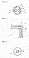
- Fig. 10 is an enlarged vertical-sectional view schematically illustrating an example of a sectional configuration of the resin element 30 of the first heat exchanger 50.
- Fig. 10 schematically illustrates a section taken along a direction perpendicular to the flow passages of the first pipe 10 and the second pipe 20.
- the resin element 30 can be formed to have a circular section. Thereby, the resin element 30 can be provided on the entire circumference of part of the inner surface of the first pipe 10. Resin elements 30 provided in such a manner are illustrated in Figs. 6 and 8 .
- Fig. 11 is an enlarged vertical-sectional view schematically illustrating another example of the invention of the sectional configuration of the resin element 30 of the first heat exchanger 50.
- Fig. 11 schematically illustrates a section taken along the direction perpendicular to the flow passages of the first pipe 10 and the second pipe 20.
- the resin element 30 can be formed to have a semicircular section. Thereby, the resin element 30 can be provided only on part of the inner surface of the first pipe 10 which is located in the outer region of the flow passage therein. Resin elements 30 provided in such a manner are illustrated in Fig. 9 .
- Fig. 11 illustrates by way of example the case where two second pipes 20 are provided in the first pipe 10. In such a manner, two second pipes 20 may be provided.
- the number of the second pipes 20 is not limited to a specific number.
- Fig. 12 is an enlarged vertical-sectional view schematically illustrating still another example of the sectional configuration of the resin element 30 of the first heat exchanger 50.
- Fig. 13 is an enlarged vertical-sectional view schematically illustrating a further example of the sectional configuration of the resin element 30 of the first heat exchanger 50.
- Fig. 14 is an enlarged vertical-sectional view schematically illustrating a still further example of the sectional configuration of the resin element 30 of the first heat exchanger 50.
- Figs. 12 to 14 each schematically illustrate sections taken along the direction perpendicular to the flow passages of the first pipe 10 and the second pipe 20.
- the resin element 30 is formed to have a circular section having grooves 30A extending in the flow direction of the fluid.
- the resin element 30 can be provided on the entire circumference of part of the inner surface of the first pipe 10, as in the example illustrated in Fig. 10 .
- the resin element 30 is provided with the grooves 30A, it is possible to prevent flowing of the fluid from being hindered by the resin element 30.
- the resin element 30 is located in the first pipe 10, and thus acts as a resistance to the flow of the fluid.
- the grooves 30A are formed to cause the fluid to flow smoothly, as illustrated in Figs. 12 to 14 .
- the shape, size and number of the grooves 30A are not limited to specific ones, and it is appropriate that the shape, size and number of the grooves 30A are determined in accordance with the shape, size and number of the resin elements 30.
- a plurality of resin elements 30 may be circumferentially arranged and spaced from each other to form the grooves 30A. In this case, each of the resin elements 30 is not circular.
- the sectional shape of the resin element 30 which is taken along the direction perpendicular to the flow passages of the first pipe 10 and the second pipe 20 is not limited to a specific shape.
- the resin element 30 can be formed to have an even inner surface, as illustrated in Figs. 10 and 11 .
- the resin element 30 may be formed to have a polygonal section, as illustrated in Figs. 12 and 13 or may be formed to have a section with arcuate portions, as illustrated in Fig. 14 .
- Fig. 15 is an enlarged vertical cross-sectional view schematically illustrating a further example not forming part of the invention of the sectional configuration of the part of the first heat exchanger 50, which includes the bent portions.
- the resin element 30 will be described with reference to Fig. 15 .
- Fig. 15 illustrates by way of example the case where resin elements 30 are provided on the outer surface of the second pipe 20.
- Fig. 15 schematically illustrates a section taken along the flow passages of the first pipe 10 and the second pipe 20.
- Figs. 6 , 8 and 9 each illustrate by way of example the case where the resin elements 30 are provided on the inner surface of the first pipe 10, whereas Fig. 15 illustrates by way of example the case where the resin elements 30 are provided on the outer surface of the second pipe 20.
- This provision of the resin elements 30 means that the resin elements 30 are provided in regions in space between the inner surface of the first pipe 10 and the outer surface of the second pipe 20. It should be noted that the function of the resin elements 30 is described above with reference to Figs. 6 to 9 .
- each of the resin elements 30 is not limited to a specific one, it is appropriate that the resin elements 30 are provided at locations where at least the bent portions 10X and 20X are present, as illustrated in Fig. 15 . Because of this configuration, it is possible to prevent contact between the first pipe 10 and the second pipe 20.
- each of the resin elements 30 along the flow direction of the fluid is not limited to a specific one, the resin elements 30 along the flow direction of the fluid, as illustrated in Fig. 15 , may be formed to be longer than those of the resin elements 30 as illustrated in Figs. 6 , 8 and 9 .
- the resin elements 30 as illustrated in Figs. 6 , 8 and 9 may be provided on the outer surface of the second pipe 20.
- each resin element 30 may be formed to have a polygonal section as illustrated in Fig. 15 or may be formed to have a section having arcuate portions.
- Figs. 16 and 17 are enlarged vertical-sectional views schematically illustrating respective examples of the sectional configuration of the resin element 30 of the first heat exchanger 50.
- Figs. 16 and 17 schematically illustrate respective sections taken along the direction perpendicular to the flow passages of the first pipe 10 and the second pipe 20.
- the resin elements 30 can be each formed to have a circular section. Thereby, each resin element 30 can be provided on the entire circumference of part of the outer surface of the second pipe 20.
- the resin elements 30 formed as illustrated in Fig. 16 are provided as illustrated in Fig. 15 .
- Fig. 17 illustrates by way of example the case where two second pipes 20 are provided in the first pipe 10.
- resin elements 30 each having a circular section may be provided on the outer surfaces of the respective two second pipes 20
- a resin element 30 having a circular section may be provided on both the outer surfaces of the two second pipes 20 as illustrated in Fig. 17 .
- the number of the second pipes 20 is not limited to a specific one.
- the resin element 30 is made of resin having a heat resistance temperature of 100 degrees C or higher. In this case, even if any kind of refrigerant is applied to the heat pump water heater 100, the resin element 30 will not be deformed by heat of the refrigerant flowing in the first heat exchanger 50.
- Fig. 18 is a table indicating heat resistance temperatures of resin.
- the resin having a heat resistance temperature of 100 degrees C or higher the following kinds of resin are present: high density polyethylene; polypropylene; AS resin; ABS resin; polyethylene terephthalate; vinylidene chloride resin; polycarbonate; polyamide; acetal resin; polybutylene terephthalate; fluorine resin; phenol resin; melamine resin; polyurethane; epoxy resin; and unsaturated polyester resin. Therefore, it is appropriate that the material of the resin element 30 is selected is selected in accordance with the kind of refrigerant to be circulated in the refrigerant circuit A.
- the first heat exchanger 50 includes the first pipe 10 formed of resin, the second pipe 20 formed of metal, and resin elements 30.
- the first pipe 10 allows fluid to flow through the first pipe 10.
- the second pipe 20 is provided in the first pipe 10, and allows refrigerant to flow through the second pipe 20.
- the resin elements 30 are each formed as an element separate from the first pipe 10 and the second pipe 20, and provided in regions in space between the inner surface of the first pipe 10 and the outer surface of the second pipe 20.
- the resin elements 30 each formed as a element separate from the first pipe 10 and the second pipe 20 are provided in regions in space provided between the inner surface of the first pipe 10 and the outer surface of the second pipe 20, it is possible to prevent contact between the first pipe 10 and second pipe 20 without adopting a complexed structure. Furthermore, in the first heat exchanger 50, it is possible to prevent contact between the first pipe 10 and the second pipe 20 at a low cost, as compared with the case where a complexed structure is applied.
- the resin elements 30 and the first pipe 10 are formed of different kinds of resin, the resin elements 30 can prevent the first heat exchanger 50 without deforming the first pipe 10.
- the resin elements 30 are each provided at least within an area from the refrigerant inlet 20a of the second pipe 20 to a position which is separated from the refrigerant inlet 20a by 5% of the entire length of the second pipe 20.
- the resin elements 50 are each located at a region on which heat of the refrigerant has a great effect. Thereby, the heat of the refrigerant flowing in the second pipe 20 is not easily transmitted to the first pipe 10.
- the resin elements 30 are each formed of resin having a heat resistance temperature of 100 degrees C or higher, they are not deformed by the heat of the refrigerant flowing in the first heat exchanger 50. Therefore, in the first heat exchanger 50, the first pipe 10 and the second pipe 20 can be kept in noncontact with each other for a long time period.
- the first pipe 10 includes the bent portions 10X
- the second pipe 20 includes the bent portions 20X
- resin elements 30 are provided at the bent portions 10X and bent portions 20X. Therefore, since the resin elements 30 are provided at locations where the first pipe 10 and the second pipe 20 can be easily brought into contact with each other, it is possible to effectively prevent the first pipe 10 and the second pipe 20 from contacting each other.
- the resin elements 30 are provided only at outer peripheral sides of the bent portions 20X of the second pipe 20, it is possible to prevent contact between the first pipe 10 and the second pipe 20 with a simpler structure.
- the resin elements 30 are located on the inner surface of the first pipe 10. Thus, it is possible to provide the resin elements 30 in the first pipe 10 without using a specific element.
- the resin elements 30 are located on the outer surface of the second pipe 20. Thus, it is possible to provide the resin elements 30 in the first pipe 10 without using a specific element.
- the grooves 30A are formed at least in part of each of the resin elements 30 to extend along the flow direction of the fluid. It is therefore possible to reduce a pressure loss which is caused by provision of the resin elements 30, and thus cause the fluid to flow smoothly.
- the heat pump water heater 100 because of provision of the first heat exchanger 50 serving as a condenser (gas cooler), deformation of the first pipe 10 can be reduced, and the reliability is thus improved. Furthermore, the resin elements 30 provided in the first heat exchanger 50 are not complicated in configuration, and the heat pump water heater 100 is thus made at a low cost.
Landscapes
- Engineering & Computer Science (AREA)
- Physics & Mathematics (AREA)
- Thermal Sciences (AREA)
- Mechanical Engineering (AREA)
- General Engineering & Computer Science (AREA)
- Heat-Exchange Devices With Radiators And Conduit Assemblies (AREA)
- Details Of Fluid Heaters (AREA)
- Heat-Pump Type And Storage Water Heaters (AREA)
Claims (7)
- Wärmetauscher (50), umfassend:eine erste Leitung (10), die aus Harz gebildet ist und eingerichtet ist, zu ermöglichen, dass flüssiges Fluid durch die erste Leitung (10) strömen kann;eine zweite Leitung (20), die aus Metall gebildet ist, die in der ersten Leitung (10) vorgesehen ist und eingerichtet ist, zu ermöglichen, dass Kältemittel durch die zweite Leitung (20) strömen kann;ein Harzelement (30), das als ein von der ersten Leitung (10) und der zweiten Leitung (20) getrenntes Element ausgebildet ist und in einem Bereich in einem Raum zwischen einer Innenoberfläche der ersten Leitung (10) und einer Außenoberfläche der zweiten Leitung (20) vorgesehen ist,dadurch gekennzeichnet, dass die erste Leitung (10) und die zweite Leitung (20) jeweils gebogene Abschnitte (10X, 20X) aufweisen,wobei das Harzelement (30) zumindest zwischen einem Kältemitteleinlass (20a), der an einem Ende der zweiten Leitung (20) vorgesehen ist, und einer Position, die von dem Kältemitteleinlass (20a) um 5 % einer gesamten Länge der zweiten Leitung (20) getrennt ist, vorgesehen ist, undwobei das Harzelement (30) nur an einer äußeren peripheren Seite des gebogenen Abschnitts (20X) der zweiten Leitung (20) vorgesehen ist.
- Wärmetauscher (50) nach Anspruch 1, wobei das Harzelement (30) und die erste Leitung (10) aus verschiedenen Arten von Harz gebildet sind.
- Wärmetauscher (50) nach Anspruch 1 oder 2, wobei das Harzelement (30) aus einem Harz, aufweisend eine Wärmebeständigkeitstemperatur von 100 Grad C oder höher, gebildet ist.
- Wärmetauscher (50) nach einem der Ansprüche 1 bis 3, wobei das Harzelement (30) an der Innenoberfläche der ersten Leitung (10) vorgesehen ist.
- Wärmetauscher (50) nach einem der Ansprüche 1 bis 3, wobei das Harzelement (30) an der Außenoberfläche der zweiten Leitung (20) vorgesehen ist.
- Wärmetauscher (50) nach einem der Ansprüche 1 bis 5, wobei das Harzelement (30) eine Rille (30A) aufweist, die in zumindest einem Teil des Harzelements (30) ausgebildet ist und sich in einer Strömungsrichtung des Fluids erstreckt.
- Wärmepumpe-Wassererwärmer (100), umfassend den Wärmetauscher (50) nach einem der Ansprüche 1 bis 6 als einen Kondensator.
Applications Claiming Priority (1)
| Application Number | Priority Date | Filing Date | Title |
|---|---|---|---|
| PCT/JP2017/003147 WO2018138906A1 (ja) | 2017-01-30 | 2017-01-30 | 熱交換器及びヒートポンプ給湯器 |
Publications (3)
| Publication Number | Publication Date |
|---|---|
| EP3575724A1 EP3575724A1 (de) | 2019-12-04 |
| EP3575724A4 EP3575724A4 (de) | 2020-01-08 |
| EP3575724B1 true EP3575724B1 (de) | 2021-08-18 |
Family
ID=62978512
Family Applications (1)
| Application Number | Title | Priority Date | Filing Date |
|---|---|---|---|
| EP17894252.0A Active EP3575724B1 (de) | 2017-01-30 | 2017-01-30 | Wärmetauscher und wärmepumpenwassererhitzer |
Country Status (3)
| Country | Link |
|---|---|
| EP (1) | EP3575724B1 (de) |
| JP (1) | JP6790129B2 (de) |
| WO (1) | WO2018138906A1 (de) |
Cited By (1)
| Publication number | Priority date | Publication date | Assignee | Title |
|---|---|---|---|---|
| RU235239U1 (ru) * | 2025-02-12 | 2025-06-25 | Владимир Викторович Михайлов | Теплообменник двухтрубный |
Families Citing this family (2)
| Publication number | Priority date | Publication date | Assignee | Title |
|---|---|---|---|---|
| JP7170011B2 (ja) * | 2020-08-31 | 2022-11-11 | ジオシステム株式会社 | 熱交換装置 |
| JP2025078176A (ja) * | 2023-11-08 | 2025-05-20 | サイエンス株式会社 | 浴湯用熱交換器、および浴湯加熱用ヒートポンプ |
Family Cites Families (12)
| Publication number | Priority date | Publication date | Assignee | Title |
|---|---|---|---|---|
| DE3017574C2 (de) * | 1980-05-08 | 1985-06-05 | Wieland-Werke Ag, 7900 Ulm | Abstandshalter für koaxiale Wärmeübertrager |
| JPS5760192A (en) * | 1980-09-26 | 1982-04-10 | Ishida Sangyo Kk | Heat exchanger |
| JPS58198688A (ja) * | 1982-05-14 | 1983-11-18 | Matsushita Electric Ind Co Ltd | 熱交換器 |
| US4786088A (en) * | 1987-06-25 | 1988-11-22 | Asahi/America, Inc. | Double-containment thermoplastic pipe assembly |
| JPS6422173U (de) * | 1987-07-30 | 1989-02-03 | ||
| JPH03238128A (ja) * | 1990-02-14 | 1991-10-23 | Shinko Metal Prod Kk | 熱交換器及びその製造方法 |
| JP2008116196A (ja) * | 2006-10-13 | 2008-05-22 | Takuya Sasaki | 管式熱交換器 |
| FR2953917B1 (fr) * | 2009-12-10 | 2012-01-20 | Hutchinson | Echangeur thermique interne pour circuit de climatisation de vehicule automobile et un tel circuit |
| CN201697503U (zh) * | 2010-02-01 | 2011-01-05 | 上海醇华电子有限公司 | 一种套管式换热器 |
| JP5721532B2 (ja) * | 2010-09-27 | 2015-05-20 | 積水化学工業株式会社 | 断熱二重管 |
| JP2013011387A (ja) | 2011-06-29 | 2013-01-17 | Panasonic Corp | 熱交換器 |
| US9568249B2 (en) * | 2012-08-28 | 2017-02-14 | Denso International America, Inc. | Heat exchanger |
-
2017
- 2017-01-30 WO PCT/JP2017/003147 patent/WO2018138906A1/ja not_active Ceased
- 2017-01-30 JP JP2018564070A patent/JP6790129B2/ja not_active Expired - Fee Related
- 2017-01-30 EP EP17894252.0A patent/EP3575724B1/de active Active
Non-Patent Citations (1)
| Title |
|---|
| None * |
Cited By (1)
| Publication number | Priority date | Publication date | Assignee | Title |
|---|---|---|---|---|
| RU235239U1 (ru) * | 2025-02-12 | 2025-06-25 | Владимир Викторович Михайлов | Теплообменник двухтрубный |
Also Published As
| Publication number | Publication date |
|---|---|
| JPWO2018138906A1 (ja) | 2019-11-07 |
| WO2018138906A1 (ja) | 2018-08-02 |
| EP3575724A4 (de) | 2020-01-08 |
| EP3575724A1 (de) | 2019-12-04 |
| JP6790129B2 (ja) | 2020-11-25 |
Similar Documents
| Publication | Publication Date | Title |
|---|---|---|
| EP3492839B1 (de) | Kältekreislaufvorrichtung | |
| EP2317269B1 (de) | Wärmetauscher, kühlkreislaufvorrichtung und klimaanlagenvorrichtung | |
| US20120031601A1 (en) | Multichannel tubes with deformable webs | |
| EP2771627B1 (de) | Regenerative klimatisierungsvorrichtung | |
| WO2011046650A2 (en) | Multichannel heat exchanger with improved flow distribution | |
| EP3217115B1 (de) | Klimatisierungsvorrichtung | |
| EP1662212A2 (de) | Klimaanlage und Verfahren zur Steuerung derselben | |
| WO2020208776A1 (ja) | 空気調和装置 | |
| EP3106768B1 (de) | Wärmequellenseitige einheit und klimatisierungsvorrichtung | |
| US11499727B2 (en) | Air conditioning apparatus | |
| EP3575724B1 (de) | Wärmetauscher und wärmepumpenwassererhitzer | |
| EP1947405A1 (de) | Klimaanlage | |
| GB2574541A (en) | Refrigeration cycle device and defrost operation method for refrigeration cycle device | |
| WO2020148826A1 (ja) | 空気調和機 | |
| JP5704898B2 (ja) | 熱交換器及びこの熱交換器を備えた空気調和装置 | |
| JP2011052850A (ja) | ヒートポンプ式温水暖房装置 | |
| EP3951287A1 (de) | Kältekreislaufvorrichtung | |
| US11828502B2 (en) | Refrigerator | |
| US20240310093A1 (en) | Refrigerant distributor, heat exchanger, and air-conditioning apparatus | |
| US20210278137A1 (en) | System and Method for Manufacturing and Operating a Coaxial Tube Heat Exchanger | |
| JP4906885B2 (ja) | 冷凍サイクル装置 | |
| JP6735924B2 (ja) | 熱交換器及び冷凍サイクル装置 | |
| KR101039290B1 (ko) | 이중관 열교환기 | |
| JP6888616B2 (ja) | 熱交換装置、冷凍システム及び熱交換方法 | |
| KR20170084787A (ko) | 공기조화기 및 공기조화기에 포함되는 팽창모듈 |
Legal Events
| Date | Code | Title | Description |
|---|---|---|---|
| STAA | Information on the status of an ep patent application or granted ep patent |
Free format text: STATUS: THE INTERNATIONAL PUBLICATION HAS BEEN MADE |
|
| PUAI | Public reference made under article 153(3) epc to a published international application that has entered the european phase |
Free format text: ORIGINAL CODE: 0009012 |
|
| STAA | Information on the status of an ep patent application or granted ep patent |
Free format text: STATUS: REQUEST FOR EXAMINATION WAS MADE |
|
| 17P | Request for examination filed |
Effective date: 20190704 |
|
| AK | Designated contracting states |
Kind code of ref document: A1 Designated state(s): AL AT BE BG CH CY CZ DE DK EE ES FI FR GB GR HR HU IE IS IT LI LT LU LV MC MK MT NL NO PL PT RO RS SE SI SK SM TR |
|
| AX | Request for extension of the european patent |
Extension state: BA ME |
|
| A4 | Supplementary search report drawn up and despatched |
Effective date: 20191206 |
|
| RIC1 | Information provided on ipc code assigned before grant |
Ipc: F28D 7/10 20060101AFI20191202BHEP |
|
| DAV | Request for validation of the european patent (deleted) | ||
| DAX | Request for extension of the european patent (deleted) | ||
| STAA | Information on the status of an ep patent application or granted ep patent |
Free format text: STATUS: EXAMINATION IS IN PROGRESS |
|
| 17Q | First examination report despatched |
Effective date: 20200807 |
|
| GRAP | Despatch of communication of intention to grant a patent |
Free format text: ORIGINAL CODE: EPIDOSNIGR1 |
|
| STAA | Information on the status of an ep patent application or granted ep patent |
Free format text: STATUS: GRANT OF PATENT IS INTENDED |
|
| INTG | Intention to grant announced |
Effective date: 20210423 |
|
| GRAS | Grant fee paid |
Free format text: ORIGINAL CODE: EPIDOSNIGR3 |
|
| GRAA | (expected) grant |
Free format text: ORIGINAL CODE: 0009210 |
|
| STAA | Information on the status of an ep patent application or granted ep patent |
Free format text: STATUS: THE PATENT HAS BEEN GRANTED |
|
| AK | Designated contracting states |
Kind code of ref document: B1 Designated state(s): AL AT BE BG CH CY CZ DE DK EE ES FI FR GB GR HR HU IE IS IT LI LT LU LV MC MK MT NL NO PL PT RO RS SE SI SK SM TR |
|
| REG | Reference to a national code |
Ref country code: GB Ref legal event code: FG4D |
|
| REG | Reference to a national code |
Ref country code: CH Ref legal event code: EP |
|
| REG | Reference to a national code |
Ref country code: DE Ref legal event code: R096 Ref document number: 602017044512 Country of ref document: DE |
|
| REG | Reference to a national code |
Ref country code: IE Ref legal event code: FG4D Ref country code: AT Ref legal event code: REF Ref document number: 1422002 Country of ref document: AT Kind code of ref document: T Effective date: 20210915 |
|
| REG | Reference to a national code |
Ref country code: LT Ref legal event code: MG9D |
|
| REG | Reference to a national code |
Ref country code: NL Ref legal event code: MP Effective date: 20210818 |
|
| REG | Reference to a national code |
Ref country code: AT Ref legal event code: MK05 Ref document number: 1422002 Country of ref document: AT Kind code of ref document: T Effective date: 20210818 |
|
| PG25 | Lapsed in a contracting state [announced via postgrant information from national office to epo] |
Ref country code: LT Free format text: LAPSE BECAUSE OF FAILURE TO SUBMIT A TRANSLATION OF THE DESCRIPTION OR TO PAY THE FEE WITHIN THE PRESCRIBED TIME-LIMIT Effective date: 20210818 Ref country code: BG Free format text: LAPSE BECAUSE OF FAILURE TO SUBMIT A TRANSLATION OF THE DESCRIPTION OR TO PAY THE FEE WITHIN THE PRESCRIBED TIME-LIMIT Effective date: 20211118 Ref country code: AT Free format text: LAPSE BECAUSE OF FAILURE TO SUBMIT A TRANSLATION OF THE DESCRIPTION OR TO PAY THE FEE WITHIN THE PRESCRIBED TIME-LIMIT Effective date: 20210818 Ref country code: NO Free format text: LAPSE BECAUSE OF FAILURE TO SUBMIT A TRANSLATION OF THE DESCRIPTION OR TO PAY THE FEE WITHIN THE PRESCRIBED TIME-LIMIT Effective date: 20211118 Ref country code: PT Free format text: LAPSE BECAUSE OF FAILURE TO SUBMIT A TRANSLATION OF THE DESCRIPTION OR TO PAY THE FEE WITHIN THE PRESCRIBED TIME-LIMIT Effective date: 20211220 Ref country code: RS Free format text: LAPSE BECAUSE OF FAILURE TO SUBMIT A TRANSLATION OF THE DESCRIPTION OR TO PAY THE FEE WITHIN THE PRESCRIBED TIME-LIMIT Effective date: 20210818 Ref country code: SE Free format text: LAPSE BECAUSE OF FAILURE TO SUBMIT A TRANSLATION OF THE DESCRIPTION OR TO PAY THE FEE WITHIN THE PRESCRIBED TIME-LIMIT Effective date: 20210818 Ref country code: HR Free format text: LAPSE BECAUSE OF FAILURE TO SUBMIT A TRANSLATION OF THE DESCRIPTION OR TO PAY THE FEE WITHIN THE PRESCRIBED TIME-LIMIT Effective date: 20210818 Ref country code: ES Free format text: LAPSE BECAUSE OF FAILURE TO SUBMIT A TRANSLATION OF THE DESCRIPTION OR TO PAY THE FEE WITHIN THE PRESCRIBED TIME-LIMIT Effective date: 20210818 Ref country code: FI Free format text: LAPSE BECAUSE OF FAILURE TO SUBMIT A TRANSLATION OF THE DESCRIPTION OR TO PAY THE FEE WITHIN THE PRESCRIBED TIME-LIMIT Effective date: 20210818 |
|
| PG25 | Lapsed in a contracting state [announced via postgrant information from national office to epo] |
Ref country code: PL Free format text: LAPSE BECAUSE OF FAILURE TO SUBMIT A TRANSLATION OF THE DESCRIPTION OR TO PAY THE FEE WITHIN THE PRESCRIBED TIME-LIMIT Effective date: 20210818 Ref country code: LV Free format text: LAPSE BECAUSE OF FAILURE TO SUBMIT A TRANSLATION OF THE DESCRIPTION OR TO PAY THE FEE WITHIN THE PRESCRIBED TIME-LIMIT Effective date: 20210818 Ref country code: GR Free format text: LAPSE BECAUSE OF FAILURE TO SUBMIT A TRANSLATION OF THE DESCRIPTION OR TO PAY THE FEE WITHIN THE PRESCRIBED TIME-LIMIT Effective date: 20211119 |
|
| PG25 | Lapsed in a contracting state [announced via postgrant information from national office to epo] |
Ref country code: NL Free format text: LAPSE BECAUSE OF FAILURE TO SUBMIT A TRANSLATION OF THE DESCRIPTION OR TO PAY THE FEE WITHIN THE PRESCRIBED TIME-LIMIT Effective date: 20210818 |
|
| PG25 | Lapsed in a contracting state [announced via postgrant information from national office to epo] |
Ref country code: DK Free format text: LAPSE BECAUSE OF FAILURE TO SUBMIT A TRANSLATION OF THE DESCRIPTION OR TO PAY THE FEE WITHIN THE PRESCRIBED TIME-LIMIT Effective date: 20210818 |
|
| REG | Reference to a national code |
Ref country code: DE Ref legal event code: R097 Ref document number: 602017044512 Country of ref document: DE |
|
| PG25 | Lapsed in a contracting state [announced via postgrant information from national office to epo] |
Ref country code: SM Free format text: LAPSE BECAUSE OF FAILURE TO SUBMIT A TRANSLATION OF THE DESCRIPTION OR TO PAY THE FEE WITHIN THE PRESCRIBED TIME-LIMIT Effective date: 20210818 Ref country code: SK Free format text: LAPSE BECAUSE OF FAILURE TO SUBMIT A TRANSLATION OF THE DESCRIPTION OR TO PAY THE FEE WITHIN THE PRESCRIBED TIME-LIMIT Effective date: 20210818 Ref country code: RO Free format text: LAPSE BECAUSE OF FAILURE TO SUBMIT A TRANSLATION OF THE DESCRIPTION OR TO PAY THE FEE WITHIN THE PRESCRIBED TIME-LIMIT Effective date: 20210818 Ref country code: EE Free format text: LAPSE BECAUSE OF FAILURE TO SUBMIT A TRANSLATION OF THE DESCRIPTION OR TO PAY THE FEE WITHIN THE PRESCRIBED TIME-LIMIT Effective date: 20210818 Ref country code: CZ Free format text: LAPSE BECAUSE OF FAILURE TO SUBMIT A TRANSLATION OF THE DESCRIPTION OR TO PAY THE FEE WITHIN THE PRESCRIBED TIME-LIMIT Effective date: 20210818 Ref country code: AL Free format text: LAPSE BECAUSE OF FAILURE TO SUBMIT A TRANSLATION OF THE DESCRIPTION OR TO PAY THE FEE WITHIN THE PRESCRIBED TIME-LIMIT Effective date: 20210818 |
|
| PLBE | No opposition filed within time limit |
Free format text: ORIGINAL CODE: 0009261 |
|
| STAA | Information on the status of an ep patent application or granted ep patent |
Free format text: STATUS: NO OPPOSITION FILED WITHIN TIME LIMIT |
|
| 26N | No opposition filed |
Effective date: 20220519 |
|
| PG25 | Lapsed in a contracting state [announced via postgrant information from national office to epo] |
Ref country code: IT Free format text: LAPSE BECAUSE OF FAILURE TO SUBMIT A TRANSLATION OF THE DESCRIPTION OR TO PAY THE FEE WITHIN THE PRESCRIBED TIME-LIMIT Effective date: 20210818 |
|
| PG25 | Lapsed in a contracting state [announced via postgrant information from national office to epo] |
Ref country code: SI Free format text: LAPSE BECAUSE OF FAILURE TO SUBMIT A TRANSLATION OF THE DESCRIPTION OR TO PAY THE FEE WITHIN THE PRESCRIBED TIME-LIMIT Effective date: 20210818 Ref country code: MC Free format text: LAPSE BECAUSE OF FAILURE TO SUBMIT A TRANSLATION OF THE DESCRIPTION OR TO PAY THE FEE WITHIN THE PRESCRIBED TIME-LIMIT Effective date: 20210818 |
|
| REG | Reference to a national code |
Ref country code: CH Ref legal event code: PL |
|
| REG | Reference to a national code |
Ref country code: BE Ref legal event code: MM Effective date: 20220131 |
|
| PG25 | Lapsed in a contracting state [announced via postgrant information from national office to epo] |
Ref country code: LU Free format text: LAPSE BECAUSE OF NON-PAYMENT OF DUE FEES Effective date: 20220130 |
|
| PG25 | Lapsed in a contracting state [announced via postgrant information from national office to epo] |
Ref country code: FR Free format text: LAPSE BECAUSE OF NON-PAYMENT OF DUE FEES Effective date: 20220131 Ref country code: BE Free format text: LAPSE BECAUSE OF NON-PAYMENT OF DUE FEES Effective date: 20220131 |
|
| PG25 | Lapsed in a contracting state [announced via postgrant information from national office to epo] |
Ref country code: LI Free format text: LAPSE BECAUSE OF NON-PAYMENT OF DUE FEES Effective date: 20220131 Ref country code: CH Free format text: LAPSE BECAUSE OF NON-PAYMENT OF DUE FEES Effective date: 20220131 |
|
| PG25 | Lapsed in a contracting state [announced via postgrant information from national office to epo] |
Ref country code: IE Free format text: LAPSE BECAUSE OF NON-PAYMENT OF DUE FEES Effective date: 20220130 |
|
| P01 | Opt-out of the competence of the unified patent court (upc) registered |
Effective date: 20230512 |
|
| PGFP | Annual fee paid to national office [announced via postgrant information from national office to epo] |
Ref country code: GB Payment date: 20231207 Year of fee payment: 8 |
|
| REG | Reference to a national code |
Ref country code: DE Ref legal event code: R084 Ref document number: 602017044512 Country of ref document: DE |
|
| PG25 | Lapsed in a contracting state [announced via postgrant information from national office to epo] |
Ref country code: MK Free format text: LAPSE BECAUSE OF FAILURE TO SUBMIT A TRANSLATION OF THE DESCRIPTION OR TO PAY THE FEE WITHIN THE PRESCRIBED TIME-LIMIT Effective date: 20210818 Ref country code: CY Free format text: LAPSE BECAUSE OF FAILURE TO SUBMIT A TRANSLATION OF THE DESCRIPTION OR TO PAY THE FEE WITHIN THE PRESCRIBED TIME-LIMIT Effective date: 20210818 |
|
| PGFP | Annual fee paid to national office [announced via postgrant information from national office to epo] |
Ref country code: DE Payment date: 20231205 Year of fee payment: 8 |
|
| PG25 | Lapsed in a contracting state [announced via postgrant information from national office to epo] |
Ref country code: HU Free format text: LAPSE BECAUSE OF FAILURE TO SUBMIT A TRANSLATION OF THE DESCRIPTION OR TO PAY THE FEE WITHIN THE PRESCRIBED TIME-LIMIT; INVALID AB INITIO Effective date: 20170130 |
|
| PG25 | Lapsed in a contracting state [announced via postgrant information from national office to epo] |
Ref country code: MT Free format text: LAPSE BECAUSE OF FAILURE TO SUBMIT A TRANSLATION OF THE DESCRIPTION OR TO PAY THE FEE WITHIN THE PRESCRIBED TIME-LIMIT Effective date: 20210818 |
|
| REG | Reference to a national code |
Ref country code: DE Ref legal event code: R119 Ref document number: 602017044512 Country of ref document: DE |
|
| GBPC | Gb: european patent ceased through non-payment of renewal fee |
Effective date: 20250130 |
|
| PG25 | Lapsed in a contracting state [announced via postgrant information from national office to epo] |
Ref country code: DE Free format text: LAPSE BECAUSE OF NON-PAYMENT OF DUE FEES Effective date: 20250801 |
|
| PG25 | Lapsed in a contracting state [announced via postgrant information from national office to epo] |
Ref country code: GB Free format text: LAPSE BECAUSE OF NON-PAYMENT OF DUE FEES Effective date: 20250130 |
|
| PG25 | Lapsed in a contracting state [announced via postgrant information from national office to epo] |
Ref country code: TR Free format text: LAPSE BECAUSE OF FAILURE TO SUBMIT A TRANSLATION OF THE DESCRIPTION OR TO PAY THE FEE WITHIN THE PRESCRIBED TIME-LIMIT Effective date: 20210818 |