EP3575736A1 - Système d'indication de détonateur - Google Patents
Système d'indication de détonateur Download PDFInfo
- Publication number
- EP3575736A1 EP3575736A1 EP18275075.2A EP18275075A EP3575736A1 EP 3575736 A1 EP3575736 A1 EP 3575736A1 EP 18275075 A EP18275075 A EP 18275075A EP 3575736 A1 EP3575736 A1 EP 3575736A1
- Authority
- EP
- European Patent Office
- Prior art keywords
- state
- power source
- indicator strip
- visible marker
- munition
- Prior art date
- Legal status (The legal status is an assumption and is not a legal conclusion. Google has not performed a legal analysis and makes no representation as to the accuracy of the status listed.)
- Ceased
Links
Images

Classifications
-
- F—MECHANICAL ENGINEERING; LIGHTING; HEATING; WEAPONS; BLASTING
- F42—AMMUNITION; BLASTING
- F42C—AMMUNITION FUZES; ARMING OR SAFETY MEANS THEREFOR
- F42C11/00—Electric fuzes
- F42C11/008—Power generation in electric fuzes
-
- F—MECHANICAL ENGINEERING; LIGHTING; HEATING; WEAPONS; BLASTING
- F42—AMMUNITION; BLASTING
- F42C—AMMUNITION FUZES; ARMING OR SAFETY MEANS THEREFOR
- F42C21/00—Checking fuzes; Testing fuzes
Definitions
- the invention relates to an indication system to display unintended power displacement in munition fuzes, for example fuzes with an electronically initiation means.
- fuzes which may be mechanically or electronically initiated.
- some munitions may employ batteries to provide electrical power during operation.
- the batteries used in munitions do not provide a current until activated by the launch environment associated with the munition the fuze is controlling, however it is known that various storage and handling conditions, such as, for example the dropping of a munition, can cause unintentional activation of the battery causing a concern for both safety and subsequent operational effectiveness.
- Munitions incorporating an electrically initiated firing means such as electric detonators, exploding bridge wires, exploding foils etc. have a greater potential for unintended activation of the power source as electrical power is present within the fuze.
- Safety standards provided in NATO standardisation agreement (STANAG) 4187 requires that "positive, direct and unambiguous means of determining that the fuzing system is not armed during and after assembly and when installing the system into a munition", are required to be met by munition manufacturers. It can be achieved in a number of ways, however may be different for each munition depending on its intended functionality and construction.
- the invention herein aims to address the issues presented in the background prior art to address safety and operational concerns.
- a device for monitoring the status of a munition fuze comprising; a visible marker capable of being switched between an off state and an on state; an indicator strip, capable of actuation, from a first state to a second state; a power source, capable of activation, wherein the power source provides power to the munition initiation system, the visible marker and/or the indicator strip; wherein said visible marker and indicator strip are positioned to be visible to an observer when the fuze has been fitted for use on said munition; and wherein activation of the power source causes switching of the visible marker from an off state to an on state and actuation of the indicator strip from a first state to a second state, such that the power source's activation is indicated by the actuation of the indicator strip to its second state; and wherein the visible marker remains in an on state only if there is sufficient power to operate the initiation system.
- the device indicates whether or not sufficient electrical power is present in the power source and/or that the fuze may be in an armed, ready state.
- the activation of the power source causes the visible marker to turn from an off state to an on state, which provides a visual cue to an observer that the power source has been activated and that there is a supply of power from the power source to both the visible marker and the initiation system.
- the visible marker should preferably only draw a minimum of electrical power from the power source, without causing undue strain to the power source, to avoid draining the power source of its stored charge. As a result it is preferred that the visible marker be able to operate at as low of a current as possible, enabling the life of the power source to be as long as possible before being depleted.
- the visible marker is a light source and may be a bulb, laser diode, or a Light Emitting Diode (LED), preferably an LED, as they have low power consumption to illumination ratio.
- LED Light Emitting Diode
- the visible marker may be a mechanical indicator active in a first and second state.
- a mechanical shutter may cover a visually distinct surface, such as, for example a reflective surface. If the power source is activated the mechanical indicator moves to the second state where the mechanical shutter exposes the visually distinct surface.
- Mechanical indicators in use with a reflective surface have the advantage of not drawing a current as they reflect ambient light, however are more complex to construct.
- the visible marker remains on while the power source retains the means for providing an electronic charge large enough to operate the initiation system of the munition. This will allow a munition to be assessed for its potential use, detailing whether sufficient charge remains within the power source even if it has suffered stimulus, causing the power source to activate unintentionally.
- the initiation system of the munition may be held in the power source.
- This power source may be storage medium such as a battery, such as, for example a primary battery, reserve battery and/or capacitors.
- Reserve batteries typically require a positive stimulus to activate, such as for example, movement of the electrolyte, electrodes, or exposure to heat. Unintended activation of reserve batteries may occur due to brief exposure to one of these stimuli.
- the visible marker shows unintended activation of the power source, however if the fuze has not been inspected by the observer for some time, for example due to being in transport or storage, it may be that, following unintended activation of the power source, the visible marker is unable to draw enough current from the power source to enable it to remain in an on state or that there is insufficient power in the power source to operate the initiation system, and so may not display to the observer that the power source has been enabled. As a result, after an extended period of being active the visible marker may no longer function and return to an off state, giving the impression to the observer that the fuze retains a sufficient power source.
- the indicator strip provides a permanent indication that the power source has been activated.
- the indicator strip reacts to a stimulus to actuate from a first state to a second state, such that said second state shows to the user that the power source has functioned.
- the indicator strip may be any indicator that undergoes a visually distinct change to show that the power source has functioned.
- the indicator strip is an irreversible indicator strip, such that once the power source has functioned, the irreversible indicator strip remains in the changed state so that the observer may know the power source has functioned, even if the visible marker is inactive (due to poor power supply for example).
- the indicator strip does not require electrical power to remain in the second state, ie the changed state.
- the indicator strip may be capable of being “re-set” or replaced, but only by specific i.e. intended intervention by a skilled operative, preferably as part of specific maintenance.
- the indicator strip may provide a clear visual notification to the user that the power source has been activated.
- the visual notification may be change in physical appearance, such as, for example, colour, physical state, motifs, insignias etc.
- the indicator strip may be actuated by any suitable stimulus, such as, for example direct electrical stimulus or a thermal stimulus.
- the indicator strip may, for example react to a temperature change, such as that provided by a heating element connected to the power source, wherein said heating element is thermally linked to the indicator strip. If the power source is unintentionally activated, the heating element will also be activated, which may cause the indicator strip to melt, deform, char, burn, change colour, react, etc., thereby causing a clear visual notification to the user that the power source has been activated.
- a temperature change such as that provided by a heating element connected to the power source, wherein said heating element is thermally linked to the indicator strip.
- the heating element may be any heating element that may be powered from an electrical current.
- the heating element is a resistive heating element.
- a resistive heating element will increase in temperature once the power source is activated, causing a flow of current to pass through the heating element. This will cause a reaction to the thermochromic indicator strip, indicating that the power source has been active at some point.
- the indicator strip may be a thermochromic indicator strip, wherein the application of heat from the heating element will cause the strip to change colour.
- This colour change may be as simple as one primary colour to another, indicating the application of heat (and so power has been provided to the heating element via the power source) or the reaction may cause a message to be displayed, such as a written or picture message, which was previously hidden by the first colour prior to the heat application.
- the resistance to heat of the thermochromic indicator strip must be higher than that of the natural surrounding environment, for example average room temperature in storage or transport.
- thermochromic indicator strip should be chosen with a suitable degree of tolerance. It is considered that any thermochromic indicator strip used should be activated by a temperature in the range of from 90 to 120°C. It is further considered the activation of the thermochromic indicator strip used should have a tolerance of plus or minus 5°C.
- the indicator strip may be formed from an electrochromic material, such that a change in colour is actuated by the passing of an electric current through the indicator strip, showing that the power source has been activated.
- the indicator strip may be a mechanically activated indicator strip. Passage of current from the power source may cause mechanical movement of shutters, indicators etc. to be moved in or out of alignment to the observer, to indicate that the indicator strip has functioned and thereby that the power source has been functioned.
- an electrically fusible wire may be caused to fail by the current, said wire which restrains a spring-loaded, bi-coloured indicator. This allows the sprung mechanism to move to reveal an alternative colour by utilising a mechanical slider or cover. Once the sprung mechanism has activated the indicator may stay in this state until an intended action, such as resetting the mechanism, is carried out intentionally, by a skilled operative.
- the current provided by the power source may be passed through a bi-metallic strip comprising at least two metals.
- the current causes the temperature of the bi-metallic strip to increase, at least one of the two metals deforms, causing a bi-stable indicator mechanism to permanently move from a first position to a second position following the application of the current and thereby displaying a visual change, such as a change in colour.
- the indicator may be an electromagnetically driven mechanical slide.
- the current provided by the power source may drive the mechanical slide to either cover or display a message or other visual notification, such as a change in colour, indicating that the power source has been activated.
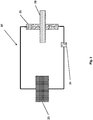
- a visible marker 14 present to highlight when power is provided to the fuze 10 initiation systems, this may have been unintentional and as a result of environmental or physical stimulus such as a knock or drop.
- Activation of the power source will supply current to the visible marker turning it from an off state to an on state and will remain in the on state until the visible marker is manually reset and when power remains in the power source (not shown), that is sufficient to operate the fuze 10 initiation systems.
- thermochromic irreversible indicator strip 18 is also present, in view of the observer (not shown).
- a current is supplied to a heating element (not shown), which increases in heat causing an irreversible reaction to the thermochromic irreversible indicator strip 18, changing its colour and showing that the power source (not shown) has been activated.
- a circuit diagram wherein there is a fuze 20 circuit with a power source 25. If the power source 25 initiates then the current will pass through the visible marker 24 and the resistive heating element 21, which would cause the visible marker to switch from an off position to an on position and the resistive heating element 21 to increase in temperature by the current passing through the resistive heating element 21. The heat from the resistive heating element 21 causes the thermochromic irreversible indicator strip 28 to undergo a reaction after reaching a certain temperature, changing from a base colour to a different colour, indicating that the power source 25 has been activated.
Landscapes
- Engineering & Computer Science (AREA)
- General Engineering & Computer Science (AREA)
- Toys (AREA)
Priority Applications (5)
| Application Number | Priority Date | Filing Date | Title |
|---|---|---|---|
| EP18275075.2A EP3575736A1 (fr) | 2018-06-01 | 2018-06-01 | Système d'indication de détonateur |
| CA3101426A CA3101426A1 (fr) | 2018-06-01 | 2019-05-30 | Systeme d'indication de fusee |
| PCT/GB2019/051476 WO2019229441A1 (fr) | 2018-06-01 | 2019-05-30 | Système d'indication de fusée |
| EP19729343.4A EP3803263B1 (fr) | 2018-06-01 | 2019-05-30 | Système d'indication pour fusée |
| US17/057,377 US11307010B2 (en) | 2018-06-01 | 2019-05-30 | Fuze indication system |
Applications Claiming Priority (1)
| Application Number | Priority Date | Filing Date | Title |
|---|---|---|---|
| EP18275075.2A EP3575736A1 (fr) | 2018-06-01 | 2018-06-01 | Système d'indication de détonateur |
Publications (1)
| Publication Number | Publication Date |
|---|---|
| EP3575736A1 true EP3575736A1 (fr) | 2019-12-04 |
Family
ID=62530160
Family Applications (1)
| Application Number | Title | Priority Date | Filing Date |
|---|---|---|---|
| EP18275075.2A Ceased EP3575736A1 (fr) | 2018-06-01 | 2018-06-01 | Système d'indication de détonateur |
Country Status (1)
| Country | Link |
|---|---|
| EP (1) | EP3575736A1 (fr) |
Citations (5)
| Publication number | Priority date | Publication date | Assignee | Title |
|---|---|---|---|---|
| US4147109A (en) * | 1977-02-17 | 1979-04-03 | General Electric Company | Controlled range fuze |
| US20070125256A1 (en) * | 2005-12-07 | 2007-06-07 | Battelle Energy Alliance, Llc | Electronic firing systems and methods for firing a device |
| US20100237197A1 (en) * | 2005-07-15 | 2010-09-23 | Rosenfield Gary C | Rocket ejection delay apparatus and/or method |
| US20140083402A1 (en) * | 2012-09-23 | 2014-03-27 | L.H.B. Ltd. | Clay-pigeon-like projectile for crowd control |
| DE102014005833A1 (de) * | 2014-04-19 | 2015-10-22 | Diehl Bgt Defence Gmbh & Co. Kg | Granate mit Airburst-Funktion |
-
2018
- 2018-06-01 EP EP18275075.2A patent/EP3575736A1/fr not_active Ceased
Patent Citations (5)
| Publication number | Priority date | Publication date | Assignee | Title |
|---|---|---|---|---|
| US4147109A (en) * | 1977-02-17 | 1979-04-03 | General Electric Company | Controlled range fuze |
| US20100237197A1 (en) * | 2005-07-15 | 2010-09-23 | Rosenfield Gary C | Rocket ejection delay apparatus and/or method |
| US20070125256A1 (en) * | 2005-12-07 | 2007-06-07 | Battelle Energy Alliance, Llc | Electronic firing systems and methods for firing a device |
| US20140083402A1 (en) * | 2012-09-23 | 2014-03-27 | L.H.B. Ltd. | Clay-pigeon-like projectile for crowd control |
| DE102014005833A1 (de) * | 2014-04-19 | 2015-10-22 | Diehl Bgt Defence Gmbh & Co. Kg | Granate mit Airburst-Funktion |
Similar Documents
| Publication | Publication Date | Title |
|---|---|---|
| EP3803263B1 (fr) | Système d'indication pour fusée | |
| AU2013225644B2 (en) | Electronic detonator | |
| EP2486365B1 (fr) | Detonateur | |
| KR101274406B1 (ko) | 이중화된 점화 유니트를 갖는 고체 에어로졸 소화기 및 그에 사용되는 점화유니트 | |
| CN105529216B (zh) | 断电复位热保护器 | |
| ES2409944B1 (es) | Extintor automático para protección de cuadros eléctricos | |
| EP3575736A1 (fr) | Système d'indication de détonateur | |
| US3500747A (en) | Safe-arm initiator | |
| GB2574255A (en) | Fuze indication system | |
| US3676945A (en) | Cartridge loaded alarm device | |
| US3504632A (en) | Time delay fuze | |
| US3858516A (en) | Thermal arming system | |
| SE437562B (sv) | Tendsystem for gasdrivna brennanordningar | |
| US2603970A (en) | Apparatus for testing projectile fuse safety devices | |
| CN106023510B (zh) | 感温报警器 | |
| US2809586A (en) | Safety delay circuit | |
| CN214010128U (zh) | 一种电子引信 | |
| RU2343399C1 (ru) | Устройство для самоликвидации ракеты | |
| US3656658A (en) | Intrusion protection system | |
| US3672810A (en) | Burner ignition and control system | |
| US3955507A (en) | Proximity fuse | |
| RU2316722C1 (ru) | Устройство для самоликвидации ракеты | |
| KR100350523B1 (ko) | 포탄용자폭신관장치 | |
| JP2006154920A (ja) | 自動火災報知器 | |
| US2961958A (en) | Thermal controlled arming device for a mine |
Legal Events
| Date | Code | Title | Description |
|---|---|---|---|
| PUAI | Public reference made under article 153(3) epc to a published international application that has entered the european phase |
Free format text: ORIGINAL CODE: 0009012 |
|
| AK | Designated contracting states |
Kind code of ref document: A1 Designated state(s): AL AT BE BG CH CY CZ DE DK EE ES FI FR GB GR HR HU IE IS IT LI LT LU LV MC MK MT NL NO PL PT RO RS SE SI SK SM TR |
|
| AX | Request for extension of the european patent |
Extension state: BA ME |
|
| STAA | Information on the status of an ep patent application or granted ep patent |
Free format text: STATUS: THE APPLICATION HAS BEEN REFUSED |
|
| 18R | Application refused |
Effective date: 20191221 |