EP3575885A1 - Ressort de barillet - Google Patents
Ressort de barillet Download PDFInfo
- Publication number
- EP3575885A1 EP3575885A1 EP18175570.3A EP18175570A EP3575885A1 EP 3575885 A1 EP3575885 A1 EP 3575885A1 EP 18175570 A EP18175570 A EP 18175570A EP 3575885 A1 EP3575885 A1 EP 3575885A1
- Authority
- EP
- European Patent Office
- Prior art keywords
- spring
- barrel
- barrel spring
- radius
- turns
- Prior art date
- Legal status (The legal status is an assumption and is not a legal conclusion. Google has not performed a legal analysis and makes no representation as to the accuracy of the status listed.)
- Granted
Links
Images
Classifications
-
- G—PHYSICS
- G04—HOROLOGY
- G04B—MECHANICALLY-DRIVEN CLOCKS OR WATCHES; MECHANICAL PARTS OF CLOCKS OR WATCHES IN GENERAL; TIME PIECES USING THE POSITION OF THE SUN, MOON OR STARS
- G04B1/00—Driving mechanisms
- G04B1/10—Driving mechanisms with mainspring
- G04B1/14—Mainsprings; Bridles therefor
- G04B1/145—Composition and manufacture of the springs
-
- B—PERFORMING OPERATIONS; TRANSPORTING
- B21—MECHANICAL METAL-WORKING WITHOUT ESSENTIALLY REMOVING MATERIAL; PUNCHING METAL
- B21D—WORKING OR PROCESSING OF SHEET METAL OR METAL TUBES, RODS OR PROFILES WITHOUT ESSENTIALLY REMOVING MATERIAL; PUNCHING METAL
- B21D11/00—Bending not restricted to forms of material mentioned in only one of groups B21D5/00, B21D7/00, B21D9/00; Bending not provided for in groups B21D5/00 - B21D9/00; Twisting
- B21D11/06—Bending into helical or spiral form; Forming a succession of return bends, e.g. serpentine form
- B21D11/07—Making serpentine-shaped articles by bending essentially in one plane
-
- B—PERFORMING OPERATIONS; TRANSPORTING
- B21—MECHANICAL METAL-WORKING WITHOUT ESSENTIALLY REMOVING MATERIAL; PUNCHING METAL
- B21D—WORKING OR PROCESSING OF SHEET METAL OR METAL TUBES, RODS OR PROFILES WITHOUT ESSENTIALLY REMOVING MATERIAL; PUNCHING METAL
- B21D11/00—Bending not restricted to forms of material mentioned in only one of groups B21D5/00, B21D7/00, B21D9/00; Bending not provided for in groups B21D5/00 - B21D9/00; Twisting
- B21D11/10—Bending specially adapted to produce specific articles, e.g. leaf springs
-
- G—PHYSICS
- G04—HOROLOGY
- G04B—MECHANICALLY-DRIVEN CLOCKS OR WATCHES; MECHANICAL PARTS OF CLOCKS OR WATCHES IN GENERAL; TIME PIECES USING THE POSITION OF THE SUN, MOON OR STARS
- G04B1/00—Driving mechanisms
- G04B1/10—Driving mechanisms with mainspring
- G04B1/16—Barrels; Arbors; Barrel axles
-
- G—PHYSICS
- G04—HOROLOGY
- G04D—APPARATUS OR TOOLS SPECIALLY DESIGNED FOR MAKING OR MAINTAINING CLOCKS OR WATCHES
- G04D3/00—Watchmakers' or watch-repairers' machines or tools for working materials
- G04D3/0002—Watchmakers' or watch-repairers' machines or tools for working materials for mechanical working other than with a lathe
- G04D3/0005—Watchmakers' or watch-repairers' machines or tools for working materials for mechanical working other than with a lathe for parts of driving means
- G04D3/001—Watchmakers' or watch-repairers' machines or tools for working materials for mechanical working other than with a lathe for parts of driving means for spring barrels
Definitions
- the present invention relates to the field of watchmaking and more specifically to a mainspring having at the end of its manufacturing process a zone of substantially zero curvature of increased length.
- the barrel springs are preformed by a calendering process to ensure a stress greater than the elastic limit over the entire length of the spring when it is drummed. This ensures that the spring can in use provide all of the available energy.
- a calendering method for barrel springs is, for example, described in the document CH 712 533 .
- the spring comprises a shell of curvature opposite to that of the calendered part and separated from the latter by a neck of length L C having a zero curvature as shown in FIG. figure 1 of the aforementioned document.
- a factor k which is the ratio between the radius of the plug of the barrel and the spring thickness greater than or equal to 10. It is however advantageous to work with a radius of the bung of smaller dimension, i.e. with a reduced factor k, which makes it possible to wind a greater number of turns around the bung.
- the spring is subjected to the armed state to significant variations in curvature may weaken the spring in the beginning of the calendered zone just after the neck because the stress is such in this place that it approaches the limit to the rupture of the spring. Indeed, the difference in curvature between the armed state of the spring and the manufactured state is very marked in this zone. This results in a significant plastic deformation of the spring during the first winding, with, as a corollary, a risk of premature failure.
- the object of the present invention is to remedy the aforementioned drawbacks by proposing a barrel spring configured to reduce the plastic deformation at the critical point when it is placed in the armed state.
- the present invention proposes to extend the neck of substantially zero curvature preceding the calendered portion. More specifically, the length of the neck is adjusted to be between 1.5 and 10 times, and preferably between 2 and 8 times, the outer radius of the calendered part at the end of the manufacturing process.
- the spring according to the invention is particularly suitable for applications with a small radius of the bung barrel for winding a higher number of turns. It is thus more specifically adapted for values of k less than 10.
- the geometry of the spring according to the invention further ensures a good spring operation with a yield between arming and disarming greater than or equal to 80%.
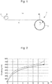
- the present invention relates to a barrel spring 1 shown in FIG. figure 1 in the manufactured state.
- the term "manufactured state” means the initial state of manufacture, before any assembly within the barrel drum.
- the barrel spring according to the invention is more specifically adapted for applications with a factor k (ratio of the diameter of the plug of the barrel to the thickness of the spring) greater than or equal to 5 and less than 10. It comprises conventionally a shell 2 and a part 3 formed of turns with an outer turn of radius R. The turns may be joined as shown in FIG. figure 1 or remote from each other (not shown).
- the shell 2 is connected to the portion 3 by a neck 4 having a substantially zero curvature forming a zone of inflection between the shell 2 and the curvature portion 3 opposite that of the shell.
- the shell 2 and the part 3 formed of turns are manufactured in known manner, for example, by hammering and calendering respectively.
- the neck has the characteristic of having a length L C increased compared to the springs of the prior art typically having Lc values less than or equal to the radius R of the outer turn. More specifically, in the manufactured state, this length L C is greater than the outer radius R of the part 3 with values between 1.5 and 10 times the radius R and preferably between 2 and 8 times the radius R. Typically, the outer radius R is between 2 and 10 mm.
- the mainspring according to the invention has a radius R of 5 mm and a length L C of 40 mm. It has for other dimensions an extended total length of 500 mm, a thickness of 90 microns and a diameter of fitted shell for a bung diameter of 1.5mm, that is to say typically between 1mm and 1.5mm. .
- the barrel spring according to the invention thus has an optimized geometry that allows in use to reduce its fragility.
- this geometry of the spring ensures a good spring operation with a yield between the torque supplied during disarming and that required for the arming greater than or equal to 80%.
- the figure 2 represents the winding curves (upper curve) and disarming curves (lower curve) for measurements made after a half-turn of disarming. For this example, a yield of 84% was obtained.
- the barrel spring according to the invention may, for example, be made of austenitic stainless steel or a Nivaflex® alloy based on cobalt-nickel-chromium containing by weight from 44 to 46% cobalt, from 20 to 22% nickel, 17 to 19% chromium, 4 to 6% iron, 3 to 5% tungsten, 3 to 5% molybdenum, 0 to 2% titanium, 0 to 1% of beryllium.
Landscapes
- Engineering & Computer Science (AREA)
- Metallurgy (AREA)
- Physics & Mathematics (AREA)
- General Physics & Mathematics (AREA)
- Mechanical Engineering (AREA)
- Springs (AREA)
Abstract
Description
- La présente invention se rapporte au domaine de l'horlogerie et plus spécifiquement à un ressort de barillet présentant à l'issue de son procédé de fabrication une zone de courbure sensiblement nulle de longueur augmentée.
- De manière connue, les ressorts de barillet sont préformés par un procédé de calandrage afin d'assurer une contrainte supérieure à la limite élastique sur toute la longueur du ressort lors de sa mise en tambour. Ceci garantit que le ressort puisse en utilisation fournir la totalité de l'énergie disponible. Un procédé de calandrage pour ressorts de barillet est, par exemple, décrit dans le document
CH 712 533 figure 1 du document précité. - Pour éviter à terme une casse du ressort monté dans le tambour du barillet, il est préconisé de maintenir un facteur k qui est le rapport entre le rayon de la bonde du barillet et l'épaisseur du ressort supérieur ou égal à 10. Il est cependant avantageux de travailler avec un rayon de la bonde de plus faible dimension, c.à.d. avec un facteur k réduit, ce qui permet d'enrouler un nombre supérieur de spires autour de la bonde. Cependant, dans ces configurations à faible rayon de la bonde, le ressort est soumis à l'état armé à des variations importantes de courbure susceptibles de fragiliser le ressort dans le début de la zone calandrée juste après le cou car la contrainte est telle en cet endroit qu'elle approche la limite à la rupture du ressort. En effet, la différence de courbure entre l'état armé du ressort et l'état fabriqué est très marquée dans cette zone. Il s'ensuit une déformation plastique importante du ressort lors du premier armage, avec, pour corollaire, un risque de rupture prématurée.
- La présente invention a pour objet de remédier aux inconvénients précités en proposant un ressort de barillet configuré pour réduire à l'endroit critique sa déformation plastique lors de sa mise en place à l'état armé.
- A cet effet, la présente invention propose d'allonger le cou de courbure sensiblement nulle précédant la partie calandrée. Plus précisément, la longueur du cou est ajustée pour être comprise entre 1,5 et 10 fois, et de préférence entre 2 et 8 fois, le rayon extérieur de la partie calandrée à l'issue du procédé de fabrication.
- Le ressort selon l'invention est particulièrement adapté pour des applications avec un faible rayon de la bonde du barillet permettant d'enrouler un nombre supérieur de spires. Il est ainsi plus spécifiquement adapté pour des valeurs de k inférieures à 10.
- La géométrie du ressort selon l'invention garantit en outre un bon fonctionnement du ressort avec un rendement entre l'armage et le désarmage supérieur ou égal à 80%.
- D'autres caractéristiques et avantages de la présente invention apparaîtront dans la description suivante de modes de réalisation préférés, présentés à titre d'exemple non limitatif en référence aux dessins annexés.
-
- La
figure 1 représente une vue en plan du ressort de barillet selon l'invention ayant une longueur Lc de cou augmentée. - La
figure 2 est un diagramme avec les courbes d'armage (courbe supérieure) et de désarmage (courbe inférieure) du ressort de barillet selon l'invention. - La présente invention se rapporte à un ressort de barillet 1 représenté à la
figure 1 à l'état fabriqué. On entend par état fabriqué, l'état initial de sortie de fabrication, avant tout montage au sein du tambour de barillet. Le ressort de barillet selon l'invention est plus spécifiquement adapté pour des applications avec un facteur k (rapport du diamètre de la bonde du barillet sur l'épaisseur du ressort) supérieur ou égal à 5 et inférieur à 10. Il comporte de manière conventionnelle un coquillon 2 et une partie 3 formée de spires avec une spire extérieure de rayon R. Les spires peuvent être jointives tel que représenté à lafigure 1 ou distantes les unes des autres (non représenté). Le coquillon 2 est relié à la partie 3 par un cou 4 ayant une courbure sensiblement nulle formant une zone d'inflexion entre le coquillon 2 et la partie 3 de courbure opposée à celle du coquillon. Le coquillon 2 et la partie 3 formée de spires sont fabriqués de manière connue, par exemple, par martelage et calandrage respectivement. - Selon l'invention, le cou a pour caractéristique de présenter une longueur LC augmentée par rapport aux ressorts de l'art antérieur ayant typiquement des valeurs Lc inférieures ou égales au rayon R de la spire extérieure. Plus précisément, à l'état fabriqué, cette longueur LC est supérieure au rayon extérieur R de la partie 3 avec des valeurs comprises entre 1,5 et 10 fois le rayon R et préférentiellement entre 2 et 8 fois le rayon R. Typiquement, le rayon extérieur R est compris entre 2 et 10 mm. A titre d'exemple, le ressort de barillet selon l'invention a un rayon R de 5 mm et une longueur LC de 40 mm. Il présente pour autres dimensions une longueur totale déployée de 500 mm, une épaisseur de 90 µm et un diamètre de coquillon ajusté pour une bonde de diamètre de 1,5mm, c'est-à-dire typiquement compris entre 1mm et 1,5mm..
- Grâce à la longueur LC augmentée, la différence de courbure entre l'état armé et l'état fabriqué est réduite dans le début de la zone calandrée. Dès lors, la déformation plastique subie par le ressort est moindre lors du premier armage, ce qui permet de limiter le risque de rupture prématurée.
- Le ressort de barillet selon l'invention présente ainsi une géométrie optimisée qui permet en utilisation de réduire sa fragilité. En outre, des mesures de couple à l'armage et au désamarge ont permis de démontrer que cette géométrie du ressort garantit un bon fonctionnement du ressort avec un rendement entre le couple fourni lors du désarmage et celui nécessaire à l'armage supérieur ou égal à 80%. A titre d'exemple, la
figure 2 représente les courbes d'armage (courbe supérieure) et de désarmage (courbe inférieure) pour des mesures effectuées après un demi-tour de désarmage. Pour cet exemple, un rendement de 84% a été obtenu. - Le ressort de barillet selon l'invention peut, à titre d'exemple, être réalisé dans un acier inoxydable austénitique ou dans un alliage Nivaflex® à base cobalt-nickel-chrome comportant en poids de 44 à 46% de cobalt, de 20 à 22% de nickel, de 17 à 19% de chrome, de 4 à 6% de fer, de 3 à 5% de tungstène, de 3 à 5% de molybdène, de 0 à 2% de titane, de 0 à 1% de béryllium.
Claims (10)
- Ressort de barillet d'horlogerie (1) comprenant, à l'état fabriqué, un coquillon (2) et une partie (3) formée de spires avec une spire extérieure de rayon R, le coquillon (2) et la partie (3) formée de spires étant reliés par un cou (4) ayant une courbure sensiblement nulle, le ressort de barillet d'horlogerie (1) étant caractérisé en ce que le cou (4) a une longueur LC comprise entre 1,5 et 10 fois le rayon R.
- Ressort de barillet (1) selon la revendication 1, caractérisé en ce que le cou (4) a une longueur LC comprise entre 2 et 8 fois le rayon R.
- Ressort de barillet (1) selon la revendication 1 ou 2, caractérisé en ce que le rayon R est compris entre 2 et 10 mm.
- Ressort de barillet (1) selon l'une quelconque des revendications 1 à 3, caractérisé en ce que la partie (3) est formée de spires jointives.
- Ressort de barillet (1) selon l'une quelconque des revendications 1 à 3, caractérisé en ce que la partie (3) est formée de spires distantes les unes des autres.
- Ressort de barillet (1) selon l'une quelconque des revendications précédentes, caractérisé en ce qu'il est destiné pour des applications avec un facteur k supérieur ou égal à 5 et inférieur à 10.
- Ressort de barillet (1) selon l'une quelconque des revendications précédentes, caractérisé en ce que, après montage au sein d'un tambour de barillet, le rendement entre le couple fourni lors du désarmage du ressort de barillet (1) et le couple nécessaire à l'armage est supérieur ou égal à 80%.
- Ressort de barillet (1) selon l'une quelconque des revendications précédentes, caractérisé en ce qu'il est réalisé dans un alliage à base cobalt-nickel-chrome, comportant en poids de 44 à 46% de cobalt, de 20 à 22% de nickel, de 17 à 19% de chrome, de 4 à 6% de fer, de 3 à 5% de tungstène, de 3 à 5% de molybdène, de 0 à 2% de titane, de 0 à 1% de béryllium.
- Ressort de barillet (1) selon l'une quelconque des revendications 1 à 7, caractérisé en ce qu'il est réalisé dans un acier inoxydable austénitique.
- Pièce d'horlogerie comprenant le ressort de barillet (1) selon l'une quelconque des revendications précédentes.
Priority Applications (4)
| Application Number | Priority Date | Filing Date | Title |
|---|---|---|---|
| EP18175570.3A EP3575885B1 (fr) | 2018-06-01 | 2018-06-01 | Barillet d'horlogerie |
| US16/401,300 US11320786B2 (en) | 2018-06-01 | 2019-05-02 | Mainspring |
| JP2019097324A JP6754866B2 (ja) | 2018-06-01 | 2019-05-24 | メインばね |
| CN201910455016.4A CN110554594B (zh) | 2018-06-01 | 2019-05-29 | 主发条 |
Applications Claiming Priority (1)
| Application Number | Priority Date | Filing Date | Title |
|---|---|---|---|
| EP18175570.3A EP3575885B1 (fr) | 2018-06-01 | 2018-06-01 | Barillet d'horlogerie |
Publications (2)
| Publication Number | Publication Date |
|---|---|
| EP3575885A1 true EP3575885A1 (fr) | 2019-12-04 |
| EP3575885B1 EP3575885B1 (fr) | 2022-09-21 |
Family
ID=62495713
Family Applications (1)
| Application Number | Title | Priority Date | Filing Date |
|---|---|---|---|
| EP18175570.3A Active EP3575885B1 (fr) | 2018-06-01 | 2018-06-01 | Barillet d'horlogerie |
Country Status (4)
| Country | Link |
|---|---|
| US (1) | US11320786B2 (fr) |
| EP (1) | EP3575885B1 (fr) |
| JP (1) | JP6754866B2 (fr) |
| CN (1) | CN110554594B (fr) |
Citations (3)
| Publication number | Priority date | Publication date | Assignee | Title |
|---|---|---|---|---|
| US4464216A (en) * | 1982-03-26 | 1984-08-07 | Hercules Incorporated | Composite negator springs |
| JP2017142215A (ja) * | 2016-02-12 | 2017-08-17 | セイコーインスツル株式会社 | ぜんまい、香箱車、ムーブメント、時計及びぜんまいの製造方法 |
| CH712533A2 (fr) | 2016-06-10 | 2017-12-15 | Nivarox Far Sa | Calandre et procédé de calandrage de ressort de barillet d'horlogerie. |
Family Cites Families (11)
| Publication number | Priority date | Publication date | Assignee | Title |
|---|---|---|---|---|
| US2192101A (en) * | 1937-06-08 | 1940-02-27 | American Steel & Wire Co | Spiral spring |
| DE1673629A1 (de) * | 1966-04-30 | 1972-04-20 | Citizen Watch Co Ltd | Aufzugsfeder fuer ein Federtriebwerk |
| US3433011A (en) * | 1966-04-30 | 1969-03-18 | Citizen Watch Co Ltd | Barrel spring |
| WO1999012080A1 (fr) * | 1997-08-28 | 1999-03-11 | Seiko Epson Corporation | Ressort, ressort moteur, ressort spiral, mecanisme d'entrainement employant ceux-ci, et compteur de temps |
| US6863435B2 (en) * | 1997-08-11 | 2005-03-08 | Seiko Epson Corporation | Spring, mainspring, hairspring, and driving mechanism and timepiece based thereon |
| JP2005140674A (ja) * | 2003-11-07 | 2005-06-02 | Seiko Epson Corp | 時計用ばね、ぜんまい、ひげぜんまい、及び時計 |
| CH698962B1 (fr) * | 2008-06-10 | 2014-10-31 | Rolex Sa | Ressort de barillet et procédé pour sa mise en forme. |
| EP2570864B1 (fr) * | 2011-09-15 | 2018-11-14 | Blancpain S.A. | Barillet d'horlogerie à diamètre de bonde réduit |
| EP2706415A3 (fr) * | 2012-09-05 | 2017-06-14 | Seiko Epson Corporation | Procédé de production de ressort de pièce d'horlogerie, dispositif de fabrication de ressort de pièce d'horlogerie, ressort de pièce d'horlogerie et pièce d'horlogerie |
| EP2746868B1 (fr) * | 2012-12-18 | 2016-04-27 | ETA SA Manufacture Horlogère Suisse | Barillet d'horlogerie |
| JP7133909B2 (ja) * | 2016-07-04 | 2022-09-09 | ロレックス・ソシエテ・アノニム | 時計用組立体の製造方法、及び該製造方法により得られる時計用組立体 |
-
2018
- 2018-06-01 EP EP18175570.3A patent/EP3575885B1/fr active Active
-
2019
- 2019-05-02 US US16/401,300 patent/US11320786B2/en active Active
- 2019-05-24 JP JP2019097324A patent/JP6754866B2/ja active Active
- 2019-05-29 CN CN201910455016.4A patent/CN110554594B/zh active Active
Patent Citations (3)
| Publication number | Priority date | Publication date | Assignee | Title |
|---|---|---|---|---|
| US4464216A (en) * | 1982-03-26 | 1984-08-07 | Hercules Incorporated | Composite negator springs |
| JP2017142215A (ja) * | 2016-02-12 | 2017-08-17 | セイコーインスツル株式会社 | ぜんまい、香箱車、ムーブメント、時計及びぜんまいの製造方法 |
| CH712533A2 (fr) | 2016-06-10 | 2017-12-15 | Nivarox Far Sa | Calandre et procédé de calandrage de ressort de barillet d'horlogerie. |
Also Published As
| Publication number | Publication date |
|---|---|
| CN110554594B (zh) | 2021-05-11 |
| US20190369558A1 (en) | 2019-12-05 |
| JP2019211471A (ja) | 2019-12-12 |
| JP6754866B2 (ja) | 2020-09-16 |
| US11320786B2 (en) | 2022-05-03 |
| EP3575885B1 (fr) | 2022-09-21 |
| CN110554594A (zh) | 2019-12-10 |
Similar Documents
| Publication | Publication Date | Title |
|---|---|---|
| EP2960531B1 (fr) | Pièce à sertir sur un support, dispositif comprenant une telle pièce et procédés de fabrication d'une telle pièce et d'un tel dispositif | |
| EP2018601B1 (fr) | Ensemble spiral-virole pour mouvement d'horlogerie | |
| EP2860592B1 (fr) | Système d'assemblage utilisant un élément de blocage élastique plan | |
| EP2469354B1 (fr) | Assemblage d'une pièce ne comportant pas de domaine plastique | |
| EP3695129B1 (fr) | Ecrou rainuré pour fixation aveugle, rivet et assemblage comportant un tel écrou | |
| EP2140151A2 (fr) | Rivet aveugle hautes performances notamment pour fixation de structure | |
| EP2520984B1 (fr) | Barillet comportant des moyens élastiques d'accumulation d'énergie supplémentaires | |
| EP3620665A1 (fr) | Vis avec gorge de rupture, fixation comprenant une telle vis, assemblage et procédé d'installation associés | |
| EP2680090A1 (fr) | Ressort-moteur pour une pièce d'horlogerie | |
| WO2012084384A2 (fr) | Assemblage d'une pièce ne comportant pas de domaine plastique | |
| EP3482088A1 (fr) | Rivet de fixation aveugle avec fût épaulé et procédé d'installation associé | |
| EP3182212A1 (fr) | Pièce composite avec moyens élastiques sous contrainte | |
| EP3280563B1 (fr) | Procédé d'assemblage permettant de fixer une première pièce à une seconde pièce | |
| EP3575885B1 (fr) | Barillet d'horlogerie | |
| EP3023844B1 (fr) | Virole flexible | |
| US9278387B2 (en) | Method for manufacturing leaf springs | |
| CH715060A2 (fr) | Ressort de barillet. | |
| FR3019864A1 (fr) | Assemblage rivete et procede de fabrication associe | |
| CH706645A1 (fr) | Système d'accouplement solidaire d'une pièce en matériau cassant à une axe métallique. | |
| EP3839656B1 (fr) | Balancier d'horlogerie | |
| EP3112955B1 (fr) | Procédé de fabrication d'une piéce comportant une étape de brunissage modifiée | |
| EP3325299B1 (fr) | Dispositif de pivot | |
| EP3052992A1 (fr) | Ressort moteur pour barillet moteur minimisant l'usure du tambour | |
| EP0246954A2 (fr) | Distributeur hydraulique rotatif et procédé d'assemblage d'un tel distributeur | |
| CH708670A2 (fr) | Système d'assemblage utilisant un élément de blocage élastique conique. |
Legal Events
| Date | Code | Title | Description |
|---|---|---|---|
| PUAI | Public reference made under article 153(3) epc to a published international application that has entered the european phase |
Free format text: ORIGINAL CODE: 0009012 |
|
| STAA | Information on the status of an ep patent application or granted ep patent |
Free format text: STATUS: THE APPLICATION HAS BEEN PUBLISHED |
|
| AK | Designated contracting states |
Kind code of ref document: A1 Designated state(s): AL AT BE BG CH CY CZ DE DK EE ES FI FR GB GR HR HU IE IS IT LI LT LU LV MC MK MT NL NO PL PT RO RS SE SI SK SM TR |
|
| AX | Request for extension of the european patent |
Extension state: BA ME |
|
| STAA | Information on the status of an ep patent application or granted ep patent |
Free format text: STATUS: REQUEST FOR EXAMINATION WAS MADE |
|
| 17P | Request for examination filed |
Effective date: 20200604 |
|
| RBV | Designated contracting states (corrected) |
Designated state(s): AL AT BE BG CH CY CZ DE DK EE ES FI FR GB GR HR HU IE IS IT LI LT LU LV MC MK MT NL NO PL PT RO RS SE SI SK SM TR |
|
| STAA | Information on the status of an ep patent application or granted ep patent |
Free format text: STATUS: EXAMINATION IS IN PROGRESS |
|
| 17Q | First examination report despatched |
Effective date: 20210423 |
|
| GRAP | Despatch of communication of intention to grant a patent |
Free format text: ORIGINAL CODE: EPIDOSNIGR1 |
|
| STAA | Information on the status of an ep patent application or granted ep patent |
Free format text: STATUS: GRANT OF PATENT IS INTENDED |
|
| INTG | Intention to grant announced |
Effective date: 20220711 |
|
| GRAS | Grant fee paid |
Free format text: ORIGINAL CODE: EPIDOSNIGR3 |
|
| GRAA | (expected) grant |
Free format text: ORIGINAL CODE: 0009210 |
|
| STAA | Information on the status of an ep patent application or granted ep patent |
Free format text: STATUS: THE PATENT HAS BEEN GRANTED |
|
| AK | Designated contracting states |
Kind code of ref document: B1 Designated state(s): AL AT BE BG CH CY CZ DE DK EE ES FI FR GB GR HR HU IE IS IT LI LT LU LV MC MK MT NL NO PL PT RO RS SE SI SK SM TR |
|
| REG | Reference to a national code |
Ref country code: GB Ref legal event code: FG4D Free format text: NOT ENGLISH |
|
| REG | Reference to a national code |
Ref country code: CH Ref legal event code: EP |
|
| REG | Reference to a national code |
Ref country code: DE Ref legal event code: R096 Ref document number: 602018040814 Country of ref document: DE |
|
| REG | Reference to a national code |
Ref country code: IE Ref legal event code: FG4D Free format text: LANGUAGE OF EP DOCUMENT: FRENCH |
|
| REG | Reference to a national code |
Ref country code: AT Ref legal event code: REF Ref document number: 1520236 Country of ref document: AT Kind code of ref document: T Effective date: 20221015 |
|
| REG | Reference to a national code |
Ref country code: LT Ref legal event code: MG9D |
|
| REG | Reference to a national code |
Ref country code: NL Ref legal event code: MP Effective date: 20220921 |
|
| PG25 | Lapsed in a contracting state [announced via postgrant information from national office to epo] |
Ref country code: SE Free format text: LAPSE BECAUSE OF FAILURE TO SUBMIT A TRANSLATION OF THE DESCRIPTION OR TO PAY THE FEE WITHIN THE PRESCRIBED TIME-LIMIT Effective date: 20220921 Ref country code: RS Free format text: LAPSE BECAUSE OF FAILURE TO SUBMIT A TRANSLATION OF THE DESCRIPTION OR TO PAY THE FEE WITHIN THE PRESCRIBED TIME-LIMIT Effective date: 20220921 Ref country code: NO Free format text: LAPSE BECAUSE OF FAILURE TO SUBMIT A TRANSLATION OF THE DESCRIPTION OR TO PAY THE FEE WITHIN THE PRESCRIBED TIME-LIMIT Effective date: 20221221 Ref country code: LV Free format text: LAPSE BECAUSE OF FAILURE TO SUBMIT A TRANSLATION OF THE DESCRIPTION OR TO PAY THE FEE WITHIN THE PRESCRIBED TIME-LIMIT Effective date: 20220921 Ref country code: LT Free format text: LAPSE BECAUSE OF FAILURE TO SUBMIT A TRANSLATION OF THE DESCRIPTION OR TO PAY THE FEE WITHIN THE PRESCRIBED TIME-LIMIT Effective date: 20220921 Ref country code: FI Free format text: LAPSE BECAUSE OF FAILURE TO SUBMIT A TRANSLATION OF THE DESCRIPTION OR TO PAY THE FEE WITHIN THE PRESCRIBED TIME-LIMIT Effective date: 20220921 |
|
| REG | Reference to a national code |
Ref country code: AT Ref legal event code: MK05 Ref document number: 1520236 Country of ref document: AT Kind code of ref document: T Effective date: 20220921 |
|
| PG25 | Lapsed in a contracting state [announced via postgrant information from national office to epo] |
Ref country code: HR Free format text: LAPSE BECAUSE OF FAILURE TO SUBMIT A TRANSLATION OF THE DESCRIPTION OR TO PAY THE FEE WITHIN THE PRESCRIBED TIME-LIMIT Effective date: 20220921 Ref country code: GR Free format text: LAPSE BECAUSE OF FAILURE TO SUBMIT A TRANSLATION OF THE DESCRIPTION OR TO PAY THE FEE WITHIN THE PRESCRIBED TIME-LIMIT Effective date: 20221222 |
|
| PG25 | Lapsed in a contracting state [announced via postgrant information from national office to epo] |
Ref country code: SM Free format text: LAPSE BECAUSE OF FAILURE TO SUBMIT A TRANSLATION OF THE DESCRIPTION OR TO PAY THE FEE WITHIN THE PRESCRIBED TIME-LIMIT Effective date: 20220921 Ref country code: RO Free format text: LAPSE BECAUSE OF FAILURE TO SUBMIT A TRANSLATION OF THE DESCRIPTION OR TO PAY THE FEE WITHIN THE PRESCRIBED TIME-LIMIT Effective date: 20220921 Ref country code: PT Free format text: LAPSE BECAUSE OF FAILURE TO SUBMIT A TRANSLATION OF THE DESCRIPTION OR TO PAY THE FEE WITHIN THE PRESCRIBED TIME-LIMIT Effective date: 20230123 Ref country code: ES Free format text: LAPSE BECAUSE OF FAILURE TO SUBMIT A TRANSLATION OF THE DESCRIPTION OR TO PAY THE FEE WITHIN THE PRESCRIBED TIME-LIMIT Effective date: 20220921 Ref country code: CZ Free format text: LAPSE BECAUSE OF FAILURE TO SUBMIT A TRANSLATION OF THE DESCRIPTION OR TO PAY THE FEE WITHIN THE PRESCRIBED TIME-LIMIT Effective date: 20220921 Ref country code: AT Free format text: LAPSE BECAUSE OF FAILURE TO SUBMIT A TRANSLATION OF THE DESCRIPTION OR TO PAY THE FEE WITHIN THE PRESCRIBED TIME-LIMIT Effective date: 20220921 |
|
| PG25 | Lapsed in a contracting state [announced via postgrant information from national office to epo] |
Ref country code: SK Free format text: LAPSE BECAUSE OF FAILURE TO SUBMIT A TRANSLATION OF THE DESCRIPTION OR TO PAY THE FEE WITHIN THE PRESCRIBED TIME-LIMIT Effective date: 20220921 Ref country code: PL Free format text: LAPSE BECAUSE OF FAILURE TO SUBMIT A TRANSLATION OF THE DESCRIPTION OR TO PAY THE FEE WITHIN THE PRESCRIBED TIME-LIMIT Effective date: 20220921 Ref country code: IS Free format text: LAPSE BECAUSE OF FAILURE TO SUBMIT A TRANSLATION OF THE DESCRIPTION OR TO PAY THE FEE WITHIN THE PRESCRIBED TIME-LIMIT Effective date: 20230121 Ref country code: EE Free format text: LAPSE BECAUSE OF FAILURE TO SUBMIT A TRANSLATION OF THE DESCRIPTION OR TO PAY THE FEE WITHIN THE PRESCRIBED TIME-LIMIT Effective date: 20220921 |
|
| REG | Reference to a national code |
Ref country code: DE Ref legal event code: R097 Ref document number: 602018040814 Country of ref document: DE |
|
| PG25 | Lapsed in a contracting state [announced via postgrant information from national office to epo] |
Ref country code: NL Free format text: LAPSE BECAUSE OF FAILURE TO SUBMIT A TRANSLATION OF THE DESCRIPTION OR TO PAY THE FEE WITHIN THE PRESCRIBED TIME-LIMIT Effective date: 20220921 Ref country code: AL Free format text: LAPSE BECAUSE OF FAILURE TO SUBMIT A TRANSLATION OF THE DESCRIPTION OR TO PAY THE FEE WITHIN THE PRESCRIBED TIME-LIMIT Effective date: 20220921 |
|
| P01 | Opt-out of the competence of the unified patent court (upc) registered |
Effective date: 20230611 |
|
| PLBE | No opposition filed within time limit |
Free format text: ORIGINAL CODE: 0009261 |
|
| STAA | Information on the status of an ep patent application or granted ep patent |
Free format text: STATUS: NO OPPOSITION FILED WITHIN TIME LIMIT |
|
| PG25 | Lapsed in a contracting state [announced via postgrant information from national office to epo] |
Ref country code: DK Free format text: LAPSE BECAUSE OF FAILURE TO SUBMIT A TRANSLATION OF THE DESCRIPTION OR TO PAY THE FEE WITHIN THE PRESCRIBED TIME-LIMIT Effective date: 20220921 |
|
| 26N | No opposition filed |
Effective date: 20230622 |
|
| PG25 | Lapsed in a contracting state [announced via postgrant information from national office to epo] |
Ref country code: SI Free format text: LAPSE BECAUSE OF FAILURE TO SUBMIT A TRANSLATION OF THE DESCRIPTION OR TO PAY THE FEE WITHIN THE PRESCRIBED TIME-LIMIT Effective date: 20220921 |
|
| PG25 | Lapsed in a contracting state [announced via postgrant information from national office to epo] |
Ref country code: MC Free format text: LAPSE BECAUSE OF FAILURE TO SUBMIT A TRANSLATION OF THE DESCRIPTION OR TO PAY THE FEE WITHIN THE PRESCRIBED TIME-LIMIT Effective date: 20220921 |
|
| PG25 | Lapsed in a contracting state [announced via postgrant information from national office to epo] |
Ref country code: MC Free format text: LAPSE BECAUSE OF FAILURE TO SUBMIT A TRANSLATION OF THE DESCRIPTION OR TO PAY THE FEE WITHIN THE PRESCRIBED TIME-LIMIT Effective date: 20220921 |
|
| REG | Reference to a national code |
Ref country code: BE Ref legal event code: MM Effective date: 20230630 |
|
| PG25 | Lapsed in a contracting state [announced via postgrant information from national office to epo] |
Ref country code: LU Free format text: LAPSE BECAUSE OF NON-PAYMENT OF DUE FEES Effective date: 20230601 |
|
| REG | Reference to a national code |
Ref country code: IE Ref legal event code: MM4A |
|
| PG25 | Lapsed in a contracting state [announced via postgrant information from national office to epo] |
Ref country code: LU Free format text: LAPSE BECAUSE OF NON-PAYMENT OF DUE FEES Effective date: 20230601 |
|
| PG25 | Lapsed in a contracting state [announced via postgrant information from national office to epo] |
Ref country code: IE Free format text: LAPSE BECAUSE OF NON-PAYMENT OF DUE FEES Effective date: 20230601 |
|
| PG25 | Lapsed in a contracting state [announced via postgrant information from national office to epo] |
Ref country code: IE Free format text: LAPSE BECAUSE OF NON-PAYMENT OF DUE FEES Effective date: 20230601 |
|
| PG25 | Lapsed in a contracting state [announced via postgrant information from national office to epo] |
Ref country code: IT Free format text: LAPSE BECAUSE OF FAILURE TO SUBMIT A TRANSLATION OF THE DESCRIPTION OR TO PAY THE FEE WITHIN THE PRESCRIBED TIME-LIMIT Effective date: 20220921 Ref country code: BE Free format text: LAPSE BECAUSE OF NON-PAYMENT OF DUE FEES Effective date: 20230630 |
|
| PG25 | Lapsed in a contracting state [announced via postgrant information from national office to epo] |
Ref country code: BG Free format text: LAPSE BECAUSE OF FAILURE TO SUBMIT A TRANSLATION OF THE DESCRIPTION OR TO PAY THE FEE WITHIN THE PRESCRIBED TIME-LIMIT Effective date: 20220921 |
|
| PG25 | Lapsed in a contracting state [announced via postgrant information from national office to epo] |
Ref country code: BG Free format text: LAPSE BECAUSE OF FAILURE TO SUBMIT A TRANSLATION OF THE DESCRIPTION OR TO PAY THE FEE WITHIN THE PRESCRIBED TIME-LIMIT Effective date: 20220921 |
|
| PGFP | Annual fee paid to national office [announced via postgrant information from national office to epo] |
Ref country code: DE Payment date: 20250520 Year of fee payment: 8 |
|
| PGFP | Annual fee paid to national office [announced via postgrant information from national office to epo] |
Ref country code: GB Payment date: 20250520 Year of fee payment: 8 |
|
| PGFP | Annual fee paid to national office [announced via postgrant information from national office to epo] |
Ref country code: FR Payment date: 20250520 Year of fee payment: 8 |
|
| PG25 | Lapsed in a contracting state [announced via postgrant information from national office to epo] |
Ref country code: CY Free format text: LAPSE BECAUSE OF FAILURE TO SUBMIT A TRANSLATION OF THE DESCRIPTION OR TO PAY THE FEE WITHIN THE PRESCRIBED TIME-LIMIT; INVALID AB INITIO Effective date: 20180601 |
|
| PG25 | Lapsed in a contracting state [announced via postgrant information from national office to epo] |
Ref country code: HU Free format text: LAPSE BECAUSE OF FAILURE TO SUBMIT A TRANSLATION OF THE DESCRIPTION OR TO PAY THE FEE WITHIN THE PRESCRIBED TIME-LIMIT; INVALID AB INITIO Effective date: 20180601 |
|
| PGFP | Annual fee paid to national office [announced via postgrant information from national office to epo] |
Ref country code: CH Payment date: 20250701 Year of fee payment: 8 |
|
| PG25 | Lapsed in a contracting state [announced via postgrant information from national office to epo] |
Ref country code: TR Free format text: LAPSE BECAUSE OF FAILURE TO SUBMIT A TRANSLATION OF THE DESCRIPTION OR TO PAY THE FEE WITHIN THE PRESCRIBED TIME-LIMIT Effective date: 20220921 |