EP3575902B1 - Capture de messages sans interruption dans un système de commande industriel - Google Patents
Capture de messages sans interruption dans un système de commande industriel Download PDFInfo
- Publication number
- EP3575902B1 EP3575902B1 EP19177005.6A EP19177005A EP3575902B1 EP 3575902 B1 EP3575902 B1 EP 3575902B1 EP 19177005 A EP19177005 A EP 19177005A EP 3575902 B1 EP3575902 B1 EP 3575902B1
- Authority
- EP
- European Patent Office
- Prior art keywords
- electronic data
- ethernet
- serial
- data messages
- field devices
- Prior art date
- Legal status (The legal status is an assumption and is not a legal conclusion. Google has not performed a legal analysis and makes no representation as to the accuracy of the status listed.)
- Active
Links
Images




Classifications
-
- G—PHYSICS
- G05—CONTROLLING; REGULATING
- G05B—CONTROL OR REGULATING SYSTEMS IN GENERAL; FUNCTIONAL ELEMENTS OF SUCH SYSTEMS; MONITORING OR TESTING ARRANGEMENTS FOR SUCH SYSTEMS OR ELEMENTS
- G05B19/00—Program-control systems
- G05B19/02—Program-control systems electric
- G05B19/04—Program control other than numerical control, i.e. in sequence controllers or logic controllers
- G05B19/042—Program control other than numerical control, i.e. in sequence controllers or logic controllers using digital processors
- G05B19/0423—Input/output
- G05B19/0425—Safety, monitoring
-
- H—ELECTRICITY
- H04—ELECTRIC COMMUNICATION TECHNIQUE
- H04L—TRANSMISSION OF DIGITAL INFORMATION, e.g. TELEGRAPHIC COMMUNICATION
- H04L43/00—Arrangements for monitoring or testing data switching networks
- H04L43/08—Monitoring or testing based on specific metrics, e.g. QoS, energy consumption or environmental parameters
- H04L43/0823—Errors, e.g. transmission errors
-
- H—ELECTRICITY
- H04—ELECTRIC COMMUNICATION TECHNIQUE
- H04L—TRANSMISSION OF DIGITAL INFORMATION, e.g. TELEGRAPHIC COMMUNICATION
- H04L41/00—Arrangements for maintenance, administration or management of data switching networks, e.g. of packet switching networks
- H04L41/06—Management of faults, events, alarms or notifications
- H04L41/0631—Management of faults, events, alarms or notifications using root cause analysis; using analysis of correlation between notifications, alarms or events based on decision criteria, e.g. hierarchy, tree or time analysis
-
- H—ELECTRICITY
- H04—ELECTRIC COMMUNICATION TECHNIQUE
- H04L—TRANSMISSION OF DIGITAL INFORMATION, e.g. TELEGRAPHIC COMMUNICATION
- H04L41/00—Arrangements for maintenance, administration or management of data switching networks, e.g. of packet switching networks
- H04L41/06—Management of faults, events, alarms or notifications
- H04L41/069—Management of faults, events, alarms or notifications using logs of notifications; Post-processing of notifications
-
- H—ELECTRICITY
- H04—ELECTRIC COMMUNICATION TECHNIQUE
- H04L—TRANSMISSION OF DIGITAL INFORMATION, e.g. TELEGRAPHIC COMMUNICATION
- H04L43/00—Arrangements for monitoring or testing data switching networks
- H04L43/08—Monitoring or testing based on specific metrics, e.g. QoS, energy consumption or environmental parameters
-
- H—ELECTRICITY
- H04—ELECTRIC COMMUNICATION TECHNIQUE
- H04L—TRANSMISSION OF DIGITAL INFORMATION, e.g. TELEGRAPHIC COMMUNICATION
- H04L43/00—Arrangements for monitoring or testing data switching networks
- H04L43/08—Monitoring or testing based on specific metrics, e.g. QoS, energy consumption or environmental parameters
- H04L43/0805—Monitoring or testing based on specific metrics, e.g. QoS, energy consumption or environmental parameters by checking availability
- H04L43/0817—Monitoring or testing based on specific metrics, e.g. QoS, energy consumption or environmental parameters by checking availability by checking functioning
-
- H—ELECTRICITY
- H04—ELECTRIC COMMUNICATION TECHNIQUE
- H04L—TRANSMISSION OF DIGITAL INFORMATION, e.g. TELEGRAPHIC COMMUNICATION
- H04L43/00—Arrangements for monitoring or testing data switching networks
- H04L43/08—Monitoring or testing based on specific metrics, e.g. QoS, energy consumption or environmental parameters
- H04L43/0823—Errors, e.g. transmission errors
- H04L43/0847—Transmission error
-
- H—ELECTRICITY
- H04—ELECTRIC COMMUNICATION TECHNIQUE
- H04L—TRANSMISSION OF DIGITAL INFORMATION, e.g. TELEGRAPHIC COMMUNICATION
- H04L41/00—Arrangements for maintenance, administration or management of data switching networks, e.g. of packet switching networks
- H04L41/06—Management of faults, events, alarms or notifications
-
- H—ELECTRICITY
- H04—ELECTRIC COMMUNICATION TECHNIQUE
- H04L—TRANSMISSION OF DIGITAL INFORMATION, e.g. TELEGRAPHIC COMMUNICATION
- H04L67/00—Network arrangements or protocols for supporting network services or applications
- H04L67/01—Protocols
- H04L67/12—Protocols specially adapted for proprietary or special-purpose networking environments, e.g. medical networks, sensor networks, networks in vehicles or remote metering networks
Definitions
- aspects of the present disclosure generally relate of the fields of networked computerized industrial control automation systems. More particularly, aspects of the present disclosure relate to a diagnostic driver that captures electronic data messages exchanged with field devices of the industrial control automation system without disrupting device communications.
- Industrial control and automation systems generally comprise process controller devices, which are typically connected via networks to large quantities of field devices throughout a process control system.
- Field devices in a process come in a variety of types and functionalities and may be created by many different vendor companies. Controlling the huge variety of field devices in concert is a vital task for ensuring the productivity and effective operations of process control systems.
- transmitters and positioners in previous generations of industrial process control equipment were comparatively simple components.
- activities associated with a field device were relatively simple.
- Industry standards like 3-15psi for pneumatic instruments or 4-20ma for electronic instruments allowed a degree of interoperability that minimized setup, configuration, and operation of analog transmitters.
- More contemporary field devices include digital data transmitting capabilities and on-device digital processors.
- These modern devices referred to generally as "intelligent" field devices, require significantly more configuration effort when setting up a new field device. Management of complex, intelligent devices requires a variety of different software interfaces, protocols, and drivers to ensure efficient interaction with each type of device.
- Gateway devices provide control and input/output (I/O) interfaces between field devices and process automation systems.
- I/O input/output
- conventional techniques for diagnosing or debugging interfacing issues between field devices and gateway devices are cumbersome procedures.
- debugging interface issues for serial ports requires disconnecting the device interface and connecting a special hardware snooper.
- debugging interface issues for Ethernet ports requires configuring a mirror port on a network switch that interfaces the gateway, connecting a station on that port, and running a packet capture tool on the station to capture messages exchanged between the gateway and the field devices.
- Such network devices are disclosed in US 2010/0082805 A1 US 2008/0080543 A1 and EP 3316052 A1 .
- aspects of the disclosure utilize a diagnostic driver embedded within a gateway device that captures messages exchanged with field devices through the gateway device within an industrial control automation system without disrupting device communications or requiring the addition of extra hardware.
- messages captured in this disruptionless manner can be transmitted to a workstation computing device ondemand for diagnosing device interface issues within the industrial control automation system.
- a system for disruptionless message capturing within an industrial control system embodying aspects of the disclosure includes a device integrator processor, a memory device, a diagnostic driver, serial interfaces, and an Ethernet interface.
- the serial interfaces are configured to communicatively couple the device integrator processor to serial field devices for use in an industrial process of a process control system.
- the communicative coupling supports communication of electronic data messages with the serial field devices in accordance with a serial electronic data communication protocol.
- the Ethernet interface is configured to communicatively couple the diagnostic driver to a computing device in accordance with an Ethernet electronic data communication protocol.
- the diagnostic driver comprises processor-executable instructions stored on the memory device.
- the instructions When executed by the device integrator processor, the instructions configure the diagnostic driver to capture electronic data messages exchanged with the serial field devices using a serial communication protocol via the serial interfaces without disrupting the communication of the messages.
- the executing instructions further configure the diagnostic driver to transmit the captured electronic data messages to the computing device via the Ethernet interfaces using a proprietary communication protocol.
- the captured messages are indicative of an abnormal condition in the communicative coupling of the device integrator processor and the serial field devices via the serial interfaces.
- Another system for disruptionless message capturing within an industrial control system embodying aspects of the disclosure includes a device integrator processor, a memory device, a diagnostic driver, and an Ethernet interface.
- the Ethernet interface is configured to communicatively couple the device integrator processor to Ethernet field devices for use in an industrial process of a process control system.
- the communicative coupling supports communication of electronic data messages with the Ethernet field devices in accordance with one or more Ethernet electronic data communication protocols.
- the Ethernet interface is further configured to communicatively couple the diagnostic driver to a diagnostic computing device in accordance with an Ethernet electronic data communication protocol.
- the diagnostic driver comprises processor-executable instructions stored on the memory device.
- the instructions configure the diagnostic driver to capture electronic data messages exchanged with the Ethernet field devices via the Ethernet interface using one or more Ethernet communication protocols without disrupting communication of the messages.
- the captured electronic data messages are indicative of an abnormal condition in the communicative coupling of the device integrator processor and the Ethernet field devices via the Ethernet interface.
- a computer-readable medium stores processor-executable instructions that, when executed, configure a device integrator processor of a gateway device for disruptionless message capturing within an industrial control system.
- the instructions comprise coupling the device integrator processor of the gateway device to serial field devices in a process control system.
- the coupling to the serial field devices is achieved via serial interfaces of the gateway device and supports communication of serial electronic data messages with the serial field devices in accordance with at least one serial electronic data communication protocol.
- the instructions further include coupling the device integrator processor to Ethernet field devices in the process control system via Ethernet interfaces of the gateway device.
- the coupling to the Ethernet field devices supports communication of Ethernet electronic data messages with the Ethernet field devices in accordance with an Ethernet data communication protocol.
- the processor-executable instructions include coupling a diagnostic driver of the gateway device to a workstation computing device via the Ethernet interfaces, which supports communication of diagnostic Ethernet electronic data packets between the diagnostic driver and the workstation computing device.
- the instructions further include initializing the diagnostic driver within the gateway device.
- the diagnostic driver captures one or more of the serial electronic data messages communicated with the serial field devices via the serial interfaces without disrupting the communication of the serial electronic data messages.
- the diagnostic driver also captures one or more of the Ethernet electronic data messages communicated with the Ethernet field devices via the Ethernet interfaces without disrupting communication of the Ethernet electronic data messages.
- the captured serial electronic data messages are indicative of an abnormal condition in the coupling of the device integrator processor to the serial field devices via the serial interfaces and the captured Ethernet electronic data messages are indicative of an abnormal condition in the coupling of the device integrator processor to the Ethernet field devices via the Ethernet interfaces.
- a method of process control communication resilience embodying aspects of the present disclosure comprises receiving a Configurable Multi-protocol Data Stream (CMDS) at a controller from one or more connected devices, processing the received CMDS for one or more process error event codes, processing a communication correlation error based on the one or more process event error codes, and executing a communication resilience process at the controller utilizing the one or more connected devices based on the communication correlation error.
- Additional embodiments may further comprise a plurality of controllers.
- the one or more process error event codes may be at least one of an error frame, an application error, and/or a device error condition.
- Principles of the disclosure may further comprise at least one or more process control changes from the one or more connected devices. Additionally, the one or more process control changes may be at least one of a process change, a device state change, and/or an environmental change.
- a system for disruptionless message capturing within an industrial control system includes a device integrator processor, a memory device, a diagnostic driver, serial interfaces, and a mesh network interface.
- the serial interfaces are configured to communicatively couple the device integrator processor to serial field devices for use in an industrial process of a process control system.
- the communicative coupling supports communication of electronic data messages with the serial field devices in accordance with a serial electronic data communication protocol.
- the mesh network interface is configured to communicatively couple the diagnostic driver to a computing device in accordance with a mesh network electronic data communication protocol.
- the diagnostic driver comprises processor-executable instructions stored on the memory device.
- the instructions When executed by the device integrator processor, the instructions configure the diagnostic driver to capture electronic data messages exchanged with the serial field devices using a serial communication protocol via the serial interfaces without disrupting the communication of the messages.
- the executing instructions further configure the diagnostic driver to transmit the captured electronic data messages to the computing device via the mesh network interface using a proprietary communication protocol.
- the captured messages are indicative of an abnormal condition in the communicative coupling of the device integrator processor and the serial field devices via the serial interfaces.
- a computer-readable medium stores processor-executable instructions that, when executed, configure a device integrator processor of a gateway device for disruptionless message capturing within an industrial control system.
- the instructions comprise coupling the device integrator processor of the gateway device to serial field devices in a process control system.
- the coupling to the serial field devices is achieved via serial interfaces of the gateway device and supports communication of serial electronic data messages with the serial field devices in accordance with at least one serial electronic data communication protocol.
- the instructions further include coupling the device integrator processor to mesh network field devices in the process control system via mesh network interfaces of the gateway device.
- the coupling to the mesh network field devices supports communication of mesh network electronic data messages with the mesh network field devices in accordance with an mesh network data communication protocol.
- the processor-executable instructions include coupling a diagnostic driver of the gateway device to a workstation computing device via the mesh network interfaces, which supports communication of diagnostic mesh network electronic data packets between the diagnostic driver and the workstation computing device.
- the instructions further include initializing the diagnostic driver within the gateway device.
- the diagnostic driver captures one or more of the serial electronic data messages communicated with the serial field devices via the serial interfaces without disrupting the communication of the serial electronic data messages.
- the diagnostic driver also captures one or more of the mesh network electronic data messages communicated with the mesh network field devices via the mesh network interfaces without disrupting communication of the mesh network electronic data messages.
- the captured serial electronic data messages are indicative of an abnormal condition in the coupling of the device integrator processor to the serial field devices via the serial interfaces and the captured mesh network electronic data messages are indicative of an abnormal condition in the coupling of the device integrator processor to the mesh network field devices via the mesh network interfaces.
- Gateway devices provide control and input/output (I/O) interfaces between field devices and process automation systems.
- I/O input/output
- conventional techniques for diagnosing or debugging interfacing issues between field devices and gateway devices are cumbersome procedures. For example, debugging interface issues for serial ports requires disconnecting the device interface and connecting a special hardware snooper. And debugging interface issues for Ethernet ports requires configuring a mirror port on a network switch that interfaces the gateway, connecting a station on that port, and running a packet capture tool on the station to capture messages exchanged between the gateway and the field devices.
- these conventional techniques require disrupting communications with the devices and/or adding extra hardware in the communication path to the devices.
- a process control system 100 embodying aspects of the disclosure comprises a gateway device 102, Ethernet field devices 104, serial field devices 106, workstations and controllers 108, interface devices 110, clock signals 112, and a power source 114.
- the gateway device 102 includes a device integrator processor 118, a memory storage device 120, and a plurality of input/output data interfaces configured to support electronic data communications with field devices as described herein.
- the gateway device 102 is communicatively and/or electrically coupled to the Ethernet field devices 104, the serial field devices 106, the workstations and controllers 108, the interface devices 110, the clock signals 112, and the power source 114.
- gateway device 102 Aspects of process control system 100, including gateway device 102, are further described herein and in U.S. Patent Application Serial No. 15/794,746, filed October 26, 2017 , entitled MULTI-PROTOCOL GATEWAY WITH CONTROL IN A PROCESS CONTROL SYSTEM and in U.S. Patent Application Serial No. 14/872,590, filed October 1, 2015 , entitled MULTI-CORE DEVICE WITH SEPARATE REDUNDANCY SCHEMES IN A PROCESS CONTROL SYSTEM.
- the gateway device 102 may be referred to as an embedded external device integrator (eEDI) device.
- eEDI embedded external device integrator
- FIG. 1 shows the gateway device 102 configured for communication with other devices in the process control system 100.
- the communications between the gateway device 102 and other devices of process control system 100 comprise requests and commands from the gateway device 102 to the other devices and responses and other data from the other devices to the gateway device 102.
- the communications between the gateway device 102 and other devices of process control system 100 comprise one or more publication-subscription ("pub-sub") protocols (e.g., Object Linking and Embedding (OLE) for Process Control (OPC) protocol, etc.) in which gateway device 102 is notified when field inputs change.
- the gateway device 102 is connected to a power source 114 and a clock signal 112, which enables the gateway device 102 and modules therein to operate in synch.
- the gateway device 102 connects to one or more interface devices 110, which are used to communicate information, such as status information, from the gateway device 102 to human operators, for example.
- the interface devices 110 communicate information from gateway device 102 to operators via one or more input/output devices, such as a visual display or other interface.
- the gateway device 102 is referred to as a station and includes a diagnostic driver embodied in processor-executable instructions stored on memory storage device 120 and executed by device integrator processor 118 as further described herein.
- the devices of process control system 100 connected to the gateway device 102 are configured to communicate through various types of interfaces.
- the workstations and controllers 108 are connected to the gateway device 102 through a mesh network 116, the Ethernet field devices 104 are connected to the gateway device 102 through Ethernet connections, and the serial field devices 106 are connected to the gateway device 102 through serial connections in the embodiment of FIG. 1 .
- the gateway device 102 communicates with serial field devices 106 using a Modbus protocol.
- the gateway device 102 may connect to other types of devices and/or communicate with connected devices using other types of communication protocols as understood by a person of ordinary skill in the art. For example, each serial port of gateway device 102 can have a unique protocol.
- an embodiment the gateway device 102 comprises a plurality of hardware layers.
- the gateway device 102 in an embodiment, comprises one or more processor modules on a base plate 202, which connects the gateway device 102 to external connections.
- An exemplary module includes, but is not limited to, a Field Device Controller 280 (FDC280) available from Schneider Electric, as further described herein, which can support multiple unique protocols running concurrently.
- FDC280 Field Device Controller 280
- One or more I/O boards 216 of the processor modules are directly attached (e.g., electrically coupled and/or physically coupled) to the base plate 202.
- the I/O boards 216 act as a conduit between the base plate 202 and processor boards 218.
- the processor boards 218 execute all of the processing tasks for the gateway device 102.
- processor boards 218 correspond to processor 118.
- Displays 210 are connected (e.g., electrically and/or communicatively connected) to the processor boards 218 in order to monitor the activity of the gateway device 102.
- the gateway device 102 interacts with (e.g., transmits data to and/or receives data from) mesh network 116 via mesh network interfaces 208, serial field devices 106 via serial interfaces 206, and Ethernet field devices 104 via Ethernet interfaces 204.
- the gateway device 102 is powered by the power source 114 connected via a power source interface 214 of the base plate 202, and processing tasks performed by the gateway device 102 are synchronized based on clock signals 112 received via clock signal interfaces 212.
- An embodiment of the I/O boards 216 provide low voltage power to the processor boards 218 by transforming higher voltage power from the base plate 202 to the desired voltage.
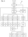
- FIG. 3 illustrates aspects of the process control system 100 from a slightly different perspective.
- the gateway device 102 includes a diagnostic driver 302.
- the gateway device 102 is communicatively and/or electrically coupled to serial field devices 106-A, 106-B, 106-C, and 106-D via the serial interfaces 206-A, 206-B, 206-C, and 206-D, respectively.
- the gateway device 102 is communicatively and/or electrically coupled to serial field device 106-E via serial interface 206-D and serial field device 106-D.
- serial field device 106-D and serial field device 106-E coupled in a daisy chain configuration
- a plurality of serial field devices may be communicatively and/or electrically coupled to serial interface 206-D in a multi-drop configuration.
- serial field device 106-E is communicatively and/or electrically coupled to serial interface 206-D directly (e.g., not via serial field device 106-D).
- serial interface 206-D may be configured for communication with a plurality of field devices (e.g., up to 32, etc.) in accordance with the RS485 communication protocol.
- serial interfaces 206-A, 206-B, 206-C and 206-D may be implemented as hardware, software, or both.
- gateway device 102 may implement one or more master or slave protocols for at least one of serial interface 206-A, 206-B, 206-C, or 206-D to communicate with the respective field devices connected to the serial interfaces.
- 206-A, 206-B, 206-C and 206-D may operate in different modes, such as RS232, RS422, or RS485.
- the gateway device 102 is communicatively and/or electrically coupled to Ethernet field devices 104-A and 104-B and a diagnostic computing device 310 via the Ethernet interface 204 and a switch device 308.
- gateway device 102 may implement one or more server or client protocols for at least one of serial interface 206-A, 206-B, 206-C, or 206-D to communicate with via Ethernet interface 204 with Ethernet field devices 104-A, 104-B, and 104-C. Gateway device 102 may implement multiple client and server protocols concurrently.
- the diagnostic computing device 310 may be connected to mesh network 116 in addition to or instead of the switch device 308. Moreover, gateway device 102 can be configured to send messages to diagnostic computing device 310 over Ethernet through the Ethernet interface 204 and/or over mesh 116 through mesh network interface(s) 208.
- Ethernet interface 204 and serial interfaces 206 are referred to as I/O ports and the Ethernet devices 104 and serial devices 106 are referred to as I/O devices.
- FIG. 3 includes four serial interfaces 206 and one Ethernet interface 204, one of ordinary skill in the art will understand that varying combinations of one or more Ethernet interfaces 204 and one or more serial interfaces 206 are within the scope of the present disclosure.
- the diagnostic driver 302 is configured to capture electronic data messages exchanged with any or all of the Ethernet field devices 104 and/or serial field devices 106 through gateway device 102 without disrupting communications with the devices (i.e., "disruptionless message capturing").
- diagnostic driver 302 captures messages exchanged with serial field devices 106 utilizing an RS232, RS422, and/or RS485 electronic data communication protocols without breaking existing connections and without utilizing additional special-purpose hardware.
- diagnostic driver 302 captures messages exchanged with Ethernet field devices 104 utilizing an Ethernet electronic data communication protocol without utilizing a mirrored port on the switch device 308.
- diagnostic driver 302 comprises processor-executable instructions embodied on memory storage device 120 and executed by device integrator processor 118.
- the diagnostic driver 302 is further configured to transmit captured electronic data messages to a computing device (e.g., workstations and controllers 108, diagnostic computing device 310, etc.).
- the diagnostic driver 302 transmits captured electronic data messages as a payload on one or more electronic data communications in accordance with a User Datagram Protocol (UDP).
- UDP User Datagram Protocol
- diagnostic driver 302 transmits captured messages to diagnostic computing device 310 on demand (e.g., when configured and enabled, in contrast to permanently enabled or disabled, etc.) via Ethernet interface 204.
- diagnostic driver 302 transmits captured messages to diagnostic computing device 310 in near real-time (e.g., in contrast to collected internally and then later analyzed) via Ethernet interface 204.
- diagnostic driver 302 may be configured (e.g., by workstations and controllers 108, diagnostic computing device 310, etc.) with the destination IP address.
- diagnostic driver 302 may be referred to as being "embedded" within gateway device 102.
- the diagnostic driver 302 can be configured for one or more operation parameters (e.g., destination IP address, a list of field devices for which the messages need to be captured, duration of capture, etc.).
- the diagnostic driver 302 may be configured by workstations and controllers 108, interface devices 110, diagnostic computing device 310, and the like. It is to be understood that in an embodiment the diagnostic computing device 310 may be a subcomponent of one of workstations and controllers 108.
- diagnostic driver 302 is configured to capture and transmit snapshots of a device interface health parameter of serial field devices 106 with serial interfaces 206 and/or Ethernet field devices 104 with Ethernet interface 204.
- Exemplary device interface health parameters include, but are not limited to, the number of cumulative communication timeouts, checksum errors, framing errors for selected devices, and the like.
- the diagnostic computing device 310 is configured to receive messages from diagnostic driver 302, parse the received messages, filter the parsed messages, and store the filtered messages for easy viewing and analysis.
- the filtered and stored messages may be used to diagnose device interface issues between serial field devices 106 and serial interfaces 206 and/or Ethernet field devices 104 and Ethernet interface 204, for example.
- FIG. 4 illustrates an exemplary message capture and transmission process, generally indicated at 400, performed by diagnostic driver 302.
- diagnostic driver 302 is similar to any other driver but creation of devices under diagnostic driver 302 is not allowed (e.g., no device is needed under diagnostic driver 302 for any reason). Selection of field devices 104, 106 whose messages are to be captured for diagnosis is accomplished via custom parameters of the driver, as further described herein.
- the diagnostic driver 302 is deployed from workstations and controllers 108, for example. In other words, the configuration is downloaded from workstations and controllers 108 to gateway device 102.
- the diagnostic driver 302 may be referred to as a log driver, such as an ECB200 driver for example.
- an executing program in gateway device 102 creates diagnostic driver 302 under an Ethernet port (e.g., Ethernet interface 204) with a Driver ID (DRVRID) of "X".
- DRVRID Driver ID
- the logging Driver ID is 3.
- an IP address and port number of a computing device that will receive transmitted messages are specified in a custom parameter (e.g., CPARM1) of diagnostic driver 302.
- diagnostic driver 302 is deployed it is set to an initialized state 404 (i.e., goes online).
- diagnostic driver 302 is initialized in response to a specific user action, such as turning the driver online from a human-machine interface (HMI), for example.
- HMI human-machine interface
- diagnostic driver 302 starts 406, which creates a queue 408 within memory storage device 120.
- the queue 408 is a contiguous portion within memory storage device 120 that is permanently allocated during initialization 404.
- queue 408 is a circular queue having a size of two megabytes (MB). No further dynamic memory allocation or de-allocation is performed at runtime, which results in no memory fragmentation.
- diagnostic driver 302 creates 406 a logging task during initialization 404.
- diagnostic driver 302 captures the electronic data messages in transaction logs at 410.
- each task specific to processing communication to each device is the component that makes this determination.
- the captured messages are discarded at 414 (e.g., removed from memory storage device 120, etc.).
- the diagnostic driver 302 is determined to be initialized at 412, the captured messages are sent at 416 to the queue 408.
- diagnostic driver 302 pops the first message from the front of queue 408 and transmits, at 420, the popped message to a receiver computing device (e.g., diagnostic computing device 310) via a User Datagram Protocol (UDP).
- a receiver computing device e.g., diagnostic computing device 3
- UDP User Datagram Protocol
- diagnostic driver 302 utilizes the custom parameters further described herein (e.g., IP address, port, etc.) to determine to which receiver computing device to transmit the popped messages.
- messages may be popped from queue 408 to a buffer to temporarily store the messages (e.g., while the connection to the receiver computing device is experiencing congestion, etc.).
- diagnostic driver 302 is configured to save the last message exchanged on each of the I/O ports (e.g., Ethernet interface 204, serial interfaces 206, etc.) of gateway device 102. Additionally, diagnostic driver 302 is configured to transmit those last saved messages to a computing device (e.g., diagnostic computing device 310) via Ethernet interface 204 in response to a manual trigger received from an external application (e.g., executing on diagnostic computing device 310, workstations and controllers 108, etc.).
- a computing device e.g., diagnostic computing device 310
- an external application e.g., executing on diagnostic computing device 310, workstations and controllers 108, etc.
- This set of features may be utilized to diagnose intermittent communication issues with devices (e.g., Ethernet field devices 104, serial field devices 106, etc.) connected to gateway device 102, a sudden loss of communication with one or more of the devices, and/or one or more of the devices entering into an indeterminate state following the receipt of a message from gateway device 102, for example.
- devices e.g., Ethernet field devices 104, serial field devices 106, etc.
- diagnostic driver 302 is configured to accept a manual trigger from an external application (e.g., executing on diagnostic computing device 310, workstations and controllers 108, etc.) to begin message capturing 410. This capability may help troubleshoot issues related to messages exchanged with devices after an external event and/or a certain device state, for example.
- diagnostic driver 302 is configured to begin message capturing 410 upon detecting an abnormal communication state. Exemplary abnormal communication states include, but are not limited to, partial reply messages, exception reply messages, and the like.
- a system includes a device integrator processor (e.g., device integrator processor 118), a memory device (e.g., memory storage device 120), a diagnostic driver (e.g., diagnostic driver 302), serial interfaces (e.g., serial interfaces 206), and an Ethernet interface (e.g., Ethernet interface 204).
- the serial interfaces are configured to communicatively couple the device integrator processor to serial field devices (e.g., serial field devices 106) for use in an industrial process of a process control system (e.g., process control system 100).
- the communicative coupling supports communication of electronic data messages with the serial field devices in accordance with a serial electronic data communication protocol (e.g., RS232, RS422, RS485, etc.).
- a serial electronic data communication protocol e.g., RS232, RS422, RS485, etc.
- the Ethernet interface is configured to communicatively couple the diagnostic driver to a computing device (e.g., workstations and controllers 108, diagnostic computing device 310, etc.) in accordance with an Ethernet electronic data communication protocol.
- the diagnostic driver comprises processor-executable instructions stored on the memory device. When executed by the device integrator processor, the instructions configure the diagnostic driver to capture (410) electronic data messages communicated with the serial field devices via the serial interfaces and the serial communication protocol without disrupting the communication of the messages. The executing instructions further configure the diagnostic driver to transmit (420) each captured electronic data message to the computing device via the Ethernet interface.
- the captured messages are indicative of an abnormal condition in the communicative coupling of the device integrator processor and the serial field devices via the serial interfaces.
- An abnormal condition may be the result of, for example, a cyberattack.
- the transmission of the captured electronic data messages is on demand.
- the diagnostic driver further comprises processor-executable instructions stored on the memory device that, when executed by the device integrator processor, create (406) a circular queue (e.g., queue 408) within the memory device for initializing (404) the diagnostic driver and create (406) a dedicated task for capturing the electronic data messages.
- processor-executable instructions stored on the memory device that, when executed by the device integrator processor, create (406) a circular queue (e.g., queue 408) within the memory device for initializing (404) the diagnostic driver and create (406) a dedicated task for capturing the electronic data messages.
- the processor-executable instructions when executed by the device integrator processor, further configure the diagnostic driver to store (416) the captured electronic data messages in the queue and transmit a captured message to the computing device by popping the captured electronic data message from a front of the queue and including the popped electronic data message within a User Datagram Protocol packet.
- the Ethernet interface is further configured to communicatively couple the device integrator processor to Ethernet field devices (e.g., Ethernet field devices 104) for supporting communication of electronic data messages with the Ethernet field devices in accordance with the Ethernet electronic data communication protocol.
- the processor-executable instructions when executed by the device integrator processor, further configure the diagnostic driver to capture (410) the electronic data messages communicated with the Ethernet field devices via the Ethernet interface and the Ethernet electronic data communication protocol without disrupting communication of the messages.
- the captured electronic data messages are indicative of an abnormal condition in the communicative coupling of the device integrator processor and the Ethernet field devices via the Ethernet interface.
- the processor-executable instructions when executed by the device integrator processor, further configure the diagnostic driver to capture (410) a snapshot of a health state of the serial interfaces and transmit (420) the captured snapshot to the computing device via the Ethernet interface.
- system further comprises the computing device and the computing device is configured to receive the transmitted electronic data messages from the diagnostic driver, parse and filter the messages, and store the messages for diagnosis of the abnormal condition in the communicative coupling of the device integrator processor and the serial industrial process field devices via the serial interfaces.
- a system in another aspect, includes a device integrator processor (e.g., device integrator processor 118), a memory device (e.g., memory storage device 120), a diagnostic driver (e.g., diagnostic driver 302), and an Ethernet interface (e.g., Ethernet interface 204).
- the Ethernet interface is configured to communicatively couple the device integrator processor to Ethernet field devices (e.g., Ethernet field devices 104) for use in an industrial process of a process control system.
- the communicative coupling supports communication of electronic data messages with the Ethernet field devices in accordance with one or more Ethernet electronic data communication protocols.
- the Ethernet interface is further configured to communicatively couple the diagnostic driver to a diagnostic computing device (e.g., diagnostic computing device 310) in accordance with the one or more Ethernet electronic data communication protocols.
- the diagnostic driver comprises processor-executable instructions stored on the memory device. When executed by the device integrator processor, the instructions configure the diagnostic driver to capture (410) electronic data messages communicated with the Ethernet field devices via the Ethernet interface and the one or more Ethernet communication protocols without disrupting communication of the messages. The captured electronic data messages are indicative of an abnormal condition in the communicative coupling of the device integrator processor and the Ethernet field devices via the Ethernet interface.
- the processor-executable instructions when executed by the device integrator processor, further configure the diagnostic driver to transmit (420), on demand, each captured electronic data message to the computing device via the Ethernet interface.
- the diagnostic driver further comprises processor-executable instructions stored on the memory device that, when executed by the device integrator processor, create (406) a circular queue (e.g., queue 408) within the memory device for initializing (404) the diagnostic driver and create (406) a dedicated task for capturing the electronic data messages.
- processor-executable instructions stored on the memory device that, when executed by the device integrator processor, create (406) a circular queue (e.g., queue 408) within the memory device for initializing (404) the diagnostic driver and create (406) a dedicated task for capturing the electronic data messages.
- the processor-executable instructions when executed by the device integrator processor, further configure the diagnostic driver to store (416) the captured electronic data messages in the queue and transmit a captured message to the diagnostic computing device by popping the captured electronic data message from a front of the queue and including the popped electronic data message within a User Datagram Protocol packet.
- the system further comprises serial interfaces (e.g., serial interfaces 206).
- the serial interfaces are configured to communicatively couple the device integrator processor to serial field devices (e.g., serial field devices 106) in the process control system.
- the communicative coupling supports communication of electronic data messages with the serial field devices in accordance with a serial electronic data communication protocol (e.g., RS232, RS422, RS485, etc.).
- a serial electronic data communication protocol e.g., RS232, RS422, RS485, etc.
- the processor-executable instructions when executed by the device integrator processor, further configure the diagnostic driver to capture (410) the electronic data messages communicated with the serial field devices via the serial interfaces and the serial electronic data communication protocol without disrupting communication of the messages.
- the captured electronic data messages are indicative of an abnormal condition in the communicative coupling of the device integrator processor and the serial field devices via the serial interfaces.
- the processor-executable instructions when executed by the device integrator processor, further configure the diagnostic driver to capture (410) a snapshot of a health state of the Ethernet interface and transmit (420) the captured snapshot to the computing device via the Ethernet interface.
- system further comprises the computing device and the computing device is configured to receive the transmitted electronic data messages from the diagnostic driver, parse and filter the messages, and store the messages for diagnosis of the abnormal condition in the communicative coupling of the device integrator processor and the Ethernet field devices via the Ethernet interface.
- a device integrator processor e.g., device integrator processor 118 of a gateway device (e.g., gateway device 102) is coupled to serial field devices (e.g., serial field devices 106) in a process control system (e.g., process control system 100).
- serial interfaces e.g., serial interfaces 206 of the gateway device and supports communication of serial electronic data messages with the serial field devices in accordance with at least one serial electronic data communication protocol (e.g., RS232, RS422, RS485, etc.).
- the method further includes coupling the device integrator processor to Ethernet field devices (e.g., Ethernet field devices 104) in the process control system via Ethernet interfaces (e.g., Ethernet interfaces 204) of the gateway device.
- Ethernet field devices e.g., Ethernet field devices 10
- the coupling supports communication of Ethernet electronic data messages with the Ethernet field devices in accordance with an Ethernet data communication protocol.
- a diagnostic driver e.g., diagnostic driver 302 of the gateway device is coupled to a workstation computing device (e.g., workstation computing device 108).
- the diagnostic driver comprises processor-executable instructions stored on a memory device (e.g., memory storage device 120) of the gateway device and executed by the device integrator processor.
- the coupling is achieved via the Ethernet interfaces and supports communication of diagnostic Ethernet electronic data packets between the diagnostic driver and the workstation computing device.
- the method further includes initializing (404) the diagnostic driver within the gateway device.
- the diagnostic driver captures (410) one or more of the serial electronic data messages communicated with the serial field devices via the serial interfaces without disrupting the communication of the serial electronic data messages.
- the diagnostic driver also captures (410) one or more of the Ethernet electronic data messages communicated with the Ethernet field devices via the Ethernet interfaces without disrupting communication of the Ethernet electronic data messages.
- the captured serial electronic data messages are indicative of an abnormal condition in the coupling of the device integrator processor to the serial field devices via the serial interfaces and the captured Ethernet electronic data messages are indicative of an abnormal condition in the coupling of the device integrator processor to the Ethernet field devices via the Ethernet interfaces.
- the diagnostic driver or another component may capture and store a predetermined number (e.g., five) of the last packets or messages received. In the event of an abnormal condition in the system, the stored packets or messages may be analyzed to determine the cause of the abnormal condition. In some embodiments, the diagnostic driver or another component may capture and/or store packets or messages if an abnormal condition is detected. Configuration information may specify what constitutes an abnormal condition.
- initializing the diagnostic driver comprises creating (406) a queue (e.g., queue 408) within the memory device and creating (406) a dedicated task for capturing the serial electronic data messages and the Ethernet electronic data messages.
- the method further includes the diagnostic driver storing (416) the captured serial electronic data messages and the captured Ethernet electronic data messages in the queue.
- the method further includes transmitting (420), on demand, the captured serial electronic data messages and the captured Ethernet electronic data messages to the workstation computing device via the Ethernet interfaces.
- the transmitting includes popping (418) the serial electronic data messages and the Ethernet electronic data messages from the queue and including the popped messages within a User Datagram Protocol packet.
- the method further includes the diagnostic driver capturing (410) snapshots of a health state of the serial interfaces and the Ethernet interfaces and transmitting (420) the captured snapshots to the workstation computing device via the Ethernet interface.
- FIG. 5 is an exemplary flow diagram illustrating a method of process control communication resilience, generally indicated at 500.
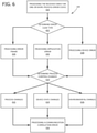
- FIG. 6 is an exemplary flow diagram illustrating additional embodiments of a method of process control communication resilience, generally indicated at 600.
- a gateway device (102) may receive data from one or more field devices (e.g. 106-A) connected to the gateway device (102). It should be appreciated that each field device may exchange data with the gateway (102) via an associated highly configurable protocol.
- This Configurable Multi-protocol Data Stream (CMDS) may operate over a variety of protocols and media, such as, but not limited to wired, wireless, Wi-Fi, Bluetooth, 6LoPan, NFC, RS-232, RS-422, RS-485, ethernet, Modbus, and/or other media and/or protocols appropriate for devices used in such applications described herein.
- a gateway device receives a CMDS from one or more of the devices connected devices (502).
- each connected device may have a unique associated data stream that may contain a variety of information including device data, process data, sensor data, environmental data, historic data, and/or error data.
- a gateway device (102) processes the received CMDS for one or more process error event codes (504).
- error codes may be identified (602) and may be utilized for further processing.
- error codes may include an error frame (604), application error (606), and or device error (608).
- Other errors may exist that may be obtained from the one or more devices, external data storage, such as a historical data repository, and/or the gateway device (102) itself may be a source of additional errors.
- Process changes may include, but are not limited to, planned alterations to a process to obtain a different result. An example may be to increase the temperature of a mixture to cause a faster cure time. In such an example, devices utilized and timing of the new process may cause unique and/or unexpected results. Device state changes (614), expected or not due to an error condition, may also result in unique and/or unexpected process results.
- Environmental changes (616) may also occur in processes that take place in part or completely in an uncontrolled environment. As one of many examples, if an exhaust stack emits water vapor when the ambient temperature is at 70 degrees Fahrenheit, should the ambient temperature change to 20 degrees Fahrenheit, a variety of process changes may result.
- Results of these changes are processed and a communication correlation error based on the one or more process event error codes (506) and/or other information illustrated generally in FIG. 6 is created.
- Such an error correlates communication errors with process changes of the variety of types described above and errors received from the connected devices themselves, again of the variety of types described above. This correlation identifies one or more process changes, device changes, and/or environmental changes that if executed will reduce and/or eliminate the communication issues being experienced during the process under observation.
- a communication resilience process is executed at the controller utilizing the one or more connected devices based on the communication correlation error (508).
- the gateway device (102) with the provided communication resilience process will execute the necessary processes at the associated devices to effect the necessary changes to the system, process, devices, and/or environments to effect the overall change.
- a feedback loop is utilized as the connected devices continue to transmit CMDS to the gateway device (102) and continuous analysis is perfumed to identify any communication issues and ameliorate and/or eliminate same on an ongoing basis.
- a communication error may occur when oil is pumped from beyond 1000 feet below the sea floor.
- Such a communication error may inhibit an accurate reading of a pressure sensor which is responsible for measuring head pressure on a pump.
- these errant readings may cause the pump to shut down as the system determines the possibility for an over-pressure situation and line rupture.
- the gateway device (102) receives CMDS data from all the associated sensors and makes the correlation that the engagement of the additional pump utilized beyond 1000 feet is correlated with the communication error of the pressure sensor which shuts the operation down.
- a communication resilience process is executed where the pressure sensor is not engaged to read until after a determined start up time of the offending pump.
- the pump can start, emit the typical EMI due to a current inrush on a motor, and electrically settle out before the pressure sensor is engaged.
- any EMI coupling to the communication lines of the pressure sensor are reduced or eliminated to the point of not causing a communication issue any longer.
- the cycle repeats with the variety of connected devices and associated processes.
- the embodiments of the system for disruptionless message capturing within an industrial control system comprise a diagnostic driver that captures electronic data messages indicating an abnormal condition and communicated among or with serial devices via serial interfaces without disrupting the communication and transmitting the captured messages to a computing device.
- At least this foregoing combination of features comprises a system architecture that serves as a technical solution to the foregoing technical problem.
- This technical solution is not routine, is unconventional, and is not well-understood in the field of networked computerized industrial control automation systems.
- This technical solution is a practical application of the exemplary system at least because it solves the foregoing technical problem and constitutes an improvement in the technical field of networked computerized industrial control automation systems at least by allowing a user to perform debugging without disconnecting a device interface and connecting a special hardware snooper to detect and/or diagnose abnormal conditions; debug problems with Ethernet ports without configuring a mirror port on a network switch that interfaces with a gateway; debugging problems with an Ethernet port without connecting a station to the port to run a packet-capture tool; perform debugging without disrupting communications with and/or among devices; and perform debugging without adding additional hardware in a communication path (i.e., avoiding added cost and system complexity).
- the technical solution comprises, instead or in addition, using an Ethernet interface configured to communicatively couple the diagnostic driver to a diagnostic computing device with an Ethernet communication protocol, wherein the diagnostic driver captures messages in accordance with a serial communication protocol.
- an Ethernet interface configured to communicatively couple the diagnostic driver to a diagnostic computing device with an Ethernet communication protocol, wherein the diagnostic driver captures messages in accordance with a serial communication protocol.
- This technical solution is a practical application of the exemplary system at least because it solves the foregoing technical problem and constitutes an improvement in the technical field of networked computerized industrial control automation systems at least by allowing a user performing debugging not disconnecting a device interface and connecting a special hardware snooper to detect and/or diagnose abnormal conditions; debug problems with Ethernet ports without configuring a mirror port on a network switch that interfaces with a gateway; debugging problems with an Ethernet port without connecting a station to the port to run a packet-capture tool; perform debugging without disrupting communications with and/or among devices; and perform debugging without adding additional hardware in a communication path (i.e., avoiding added cost and system complexity).
- Embodiments of the present disclosure may comprise a special purpose computer including a variety of computer hardware, as described in greater detail below.
- Embodiments within the scope of the present disclosure also include computer-readable media for carrying or having computer-executable instructions or data structures stored thereon.
- Such computer-readable media can be any available media that can be accessed by a special purpose computer.
- Such computer-readable media can comprise RAM, ROM, EEPROM, CD-ROM or other optical disk storage, magnetic disk storage, or other magnetic storage devices, or any other medium that can be used to carry or store desired program code means in the form of computer-executable instructions or data structures and that can be accessed by a general purpose or special purpose computer.
- Computer-executable instructions comprise, for example, instructions and data which cause a general purpose computer, special purpose computer, or special purpose processing device to perform a certain function or group of functions.
- aspects of the disclosure may be practiced in network computing environments with many types of computer system configurations, including personal computers, hand-held devices, multi-processor systems, microprocessor-based or programmable consumer electronics, network PCs, minicomputers, mainframe computers, and the like. Aspects of the disclosure may also be practiced in distributed computing environments where tasks are performed by local and remote processing devices that are linked (either by hardwired links, wireless links, or by a combination of hardwired or wireless links) through a communications network. In a distributed computing environment, program modules may be located in both local and remote memory storage devices.
- An exemplary system for implementing aspects of the disclosure includes a special purpose computing device in the form of a conventional computer, including a processing unit, a system memory, and a system bus that couples various system components including the system memory to the processing unit.
- the system bus may be any of several types of bus structures including a memory bus or memory controller, a peripheral bus, and a local bus using any of a variety of bus architectures.
- the system memory includes read only memory (ROM) and random access memory (RAM).
- ROM read only memory
- RAM random access memory
- a basic input/output system (BIOS), containing the basic routines that help transfer information between elements within the computer, such as during start-up, may be stored in ROM.
- the computer may include any device (e.g., computer, laptop, tablet, PDA, cell phone, mobile phone, a smart television, and the like) that is capable of receiving or transmitting an IP address wirelessly to or from the internet.
- the computer may also include a magnetic hard disk drive for reading from and writing to a magnetic hard disk, a magnetic disk drive for reading from or writing to a removable magnetic disk, and an optical disk drive for reading from or writing to removable optical disk such as a CD-ROM or other optical media.
- the magnetic hard disk drive, magnetic disk drive, and optical disk drive are connected to the system bus by a hard disk drive interface, a magnetic disk drive-interface, and an optical drive interface, respectively.
- the drives and their associated computer-readable media provide nonvolatile storage of computer-executable instructions, data structures, program modules, and other data for the computer.
- exemplary environment described herein employs a magnetic hard disk, a removable magnetic disk, and a removable optical disk
- other types of computer readable media for storing data can be used, including magnetic cassettes, flash memory cards, digital video disks, Bernoulli cartridges, RAMs, ROMs, solid state drives (SSDs), and the like.
- Computer readable media can be any available media that can be accessed by the computer and includes both volatile and nonvolatile media, removable and non-removable media.
- Computer readable media may comprise computer storage media and communication media.
- Computer storage media include both volatile and nonvolatile, removable and non-removable media implemented in any method or technology for storage of information such as computer readable instructions, data structures, program modules or other data.
- Computer storage media are non-transitory and include, but are not limited to, RAM, ROM, EEPROM, flash memory or other memory technology, CD-ROM, digital versatile disks (DVD) or other optical disk storage, SSDs, magnetic cassettes, magnetic tape, magnetic disk storage or other magnetic storage devices, or any other medium which can be used to store the desired non-transitory information, which can accessed by the computer.
- communication media typically embody computer readable instructions, data structures, program modules or other data in a modulated data signal such as a carrier wave or other transport mechanism and includes any information delivery media.
- Program code means comprising one or more program modules may be stored on the hard disk, magnetic disk, optical disk, ROM, and/or RAM, including an operating system, one or more application programs, other program modules, and program data.
- a user may enter commands and information into the computer through a keyboard, pointing device, or other input device, such as a microphone, joy stick, game pad, satellite dish, scanner, or the like.
- These and other input devices are often connected to the processing unit through a serial port interface coupled to the system bus.
- the input devices may be connected by other interfaces, such as a parallel port, a game port, or a universal serial bus (USB).
- a monitor or another display device is also connected to the system bus via an interface, such as video adapter 48.
- personal computers typically include other peripheral output devices (not shown), such as speakers and printers.
- One or more aspects of the disclosure may be embodied in computer-executable instructions (i.e., software), routines, or functions stored in system memory or nonvolatile memory as application programs, program modules, and/or program data.
- the software may alternatively be stored remotely, such as on a remote computer with remote application programs.
- program modules include routines, programs, objects, components, data structures, etc. that perform particular tasks or implement particular abstract data types when executed by a processor in a computer or other device.
- the computer executable instructions may be stored on one or more tangible, non-transitory computer readable media (e.g., hard disk, optical disk, removable storage media, solid state memory, RAM, etc.) and executed by one or more processors or other devices.
- program modules may be combined or distributed as desired in various embodiments.
- functionality may be embodied in whole or in part in firmware or hardware equivalents such as integrated circuits, application specific integrated circuits, field programmable gate arrays (FPGA), and the like.
- the computer may operate in a networked environment using logical connections to one or more remote computers.
- the remote computers may each be another personal computer, a tablet, a PDA, a server, a router, a network PC, a peer device, or other common network node, and typically include many or all of the elements described above relative to the computer.
- the logical connections include a local area network (LAN) and a wide area network (WAN) that are presented here by way of example and not limitation.
- LAN local area network
- WAN wide area network
- the computer When used in a LAN networking environment, the computer is connected to the local network through a network interface or adapter. When used in a WAN networking environment, the computer may include a modem, a wireless link, or other means for establishing communications over the wide area network, such as the Internet.
- the modem which may be internal or external, is connected to the system bus via the serial port interface.
- program modules depicted relative to the computer, or portions thereof, may be stored in the remote memory storage device. It will be appreciated that the network connections shown are exemplary and other means of establishing communications over wide area network may be used.
- computer-executable instructions are stored in a memory, such as the hard disk drive, and executed by the computer.
- the computer processor has the capability to perform all operations (e.g., execute computer-executable instructions) in real-time.
- Embodiments of the disclosure may be implemented with computer-executable instructions.
- the computer-executable instructions may be organized into one or more computer-executable components or modules.
- Aspects of the disclosure may be implemented with any number and organization of such components or modules. For example, aspects of the disclosure are not limited to the specific computer-executable instructions or the specific components or modules illustrated in the figures and described herein.
- Other embodiments of the disclosure may include different computer-executable instructions or components having more or less functionality than illustrated and described herein.
- the present invention also relates to disruptionless message capturing within an industrial control system and/or capturing messages exchanged with field devices in an industrial process without disrupting communication of the messages.
- a diagnostic driver embedded within a gateway device detects abnormal conditions in connections between the gateway device and the field devices.
- the diagnostic driver captures messages indicative of the abnormal condition without disrupting message communication.
- the driver is capable of transmitting captured messages, on demand, to a workstation computing device for diagnosis of the abnormal condition.
Landscapes
- Engineering & Computer Science (AREA)
- Computer Networks & Wireless Communication (AREA)
- Signal Processing (AREA)
- Environmental & Geological Engineering (AREA)
- Physics & Mathematics (AREA)
- General Physics & Mathematics (AREA)
- Automation & Control Theory (AREA)
- Testing And Monitoring For Control Systems (AREA)
- Computer Security & Cryptography (AREA)
Claims (10)
- Système de capture de messages sans interruption à l'intérieur d'un système de commande de processus (100) comprenant :un processeur d'intégration de dispositifs (118) configuré pour communiquer des messages de données électroniques dans le système de commande de processus (100) ;un dispositif de mémoire (120) couplé au processeur d'intégration de dispositifs (118) ;un pilote de diagnostic (302) ;une pluralité d'interfaces série (206) configurées pour coupler en communication le processeur d'intégration de dispositifs (118) à un groupe de deux ou de plusieurs dispositifs de terrain série (106), les dispositifs de terrain série (106) étant destinés à une utilisation dans un processus industriel du système de commande de processus (100), le processeur d'intégration de dispositifs (118) communiquant les messages de données électroniques avec les dispositifs de terrain série (106) en accord avec au moins un protocole de communication de données électroniques série ; etune interface Ethernet (204) configurée pour coupler en communication le processeur d'intégration de dispositifs (118) à un ou plusieurs dispositifs de terrain Ethernet (104), les dispositifs de terrain Ethernet (104) étant destinés à une utilisation dans un processus industriel du système de commande de processus (100), le processeur d'intégration de dispositifs (118) communiquant les messages de données électroniques avec les dispositifs de terrain Ethernet (104) en accord avec un protocole de communication de données électroniques Ethernet ;dans lequel le pilote de diagnostic (302) comprend des instructions exécutables par processeur stockées sur le dispositif de mémoire (120), etdans lequel les instructions, quand elles sont exécutées par le processeur d'intégration de dispositifs (118), configurent le pilote de diagnostic (302) pour :pendant une initialisation du pilote de diagnostic (302), allouer de manière permanente une portion du dispositif de mémoire (120) à titre de file d'attente (408) et créer une tâche dédiée pour capturer les messages de données électroniques dans la file d'attente (408), dans lequel une initialisation du pilote de diagnostic (302) est en réponse à une action d'un utilisateur,capturer un ou plusieurs des messages de données électroniques en communication avec les dispositifs de terrain série (106) via les interfaces série (206) en accord avec le protocole de communication série sans interrompre la communication des messages de données électroniques série, ou capturer un ou plusieurs des messages de données électroniques en communication avec des dispositifs de terrain Ethernet (104) via l'interface Ethernet (204) en accord avec le protocole de communication de données électroniques Ethernet sans interrompre la communication des messages de données électroniques Ethernet, les messages de données électroniques capturés étant stockés dans la file d'attente (408) à l'intérieur du dispositif de mémoire (120),quand le pilote de diagnostic (302) est déterminé comme étant initialisé, envoyer les messages de données électroniques capturés à la file d'attente (408), ettransmettre les messages de données électroniques capturés depuis la file d'attente (408) jusqu'à un dispositif de calcul (108, 310) via l'interface Ethernet (204) pour un diagnostic de ceux-ci en relation avec la condition anormale,dans lequel au moins un des messages parmi :les messages de données électroniques capturés sont indicatifs d'une condition anormale dans le couplage en communication du processeur d'intégration de dispositifs (118) et des dispositifs de terrain série (106) via les interfaces série (206),les messages de données électroniques Ethernet capturés sont indicatifs d'une condition anormale dans le couplage en communication du processeur d'intégration de dispositifs (118) au dispositif de terrain Ethernet (104) via l'interface Ethernet (204), etdans lequel tout message de données électroniques capturé avant l'initialisation du pilote de diagnostic (302) est effacé de la file d'attente (408) à l'intérieur du dispositif de mémoire (120).
- Système selon la revendication 1, dans lequel la transmission des messages de données électroniques capturés est sur demande.
- Système selon l'une quelconque des revendications précédentes,
dans lequel l'interface Ethernet (204) est en outre configurée pour coupler en communication le pilote de diagnostic (302) au dispositif de calcul (108, 310) en accord avec le protocole de communication de données électroniques Ethernet. - Système selon l'une quelconque des revendications précédentes, dans lequel les instructions exécutables par processeur, quand elles sont exécutées par le processeur d'intégration de dispositifs (118), configurent en outre le pilote de diagnostic (302) pour transmettre, sur demande, chaque message de données électroniques capturé au dispositif de calcul (310) via l'interface Ethernet (204).
- Système selon l'une quelconque des revendications précédentes, dans lequel le pilote de diagnostic (302) comprend en outre des instructions exécutables par processeur stockées sur le dispositif de mémoire (120) qui, quand elles sont exécutées par le processeur d'intégration de dispositifs (118), configurent en outre le pilote de diagnostic (302) pour :stocker les messages de données électroniques capturés dans la file d'attente (408) ; ettransmettre un message de données électroniques capturé au dispositif de calcul (310) en retirant le message de données électroniques capturé de l'avant de la file d'attente (408) et en incluant le message de données électroniques retiré à l'intérieur d'un paquet de protocole de datagramme utilisateur.
- Système selon l'une quelconque des revendications précédentes, dans lequel les instructions exécutables par processeur, quand elles sont exécutées par le processeur d'intégration de dispositifs (118), configurent en outre le pilote de diagnostic (302) pour :capturer un instantané d'un état de santé de l'interface Ethernet (204), ettransmettre l'instantané capturé au dispositif de calcul (310) via l'interface Ethernet (204).
- Système selon l'une quelconque des revendications précédentes, comprenant en outre le dispositif de calcul (310), dans lequel le dispositif de calcul (310) est configuré pour :recevoir les messages de données électroniques transmis depuis le pilote de diagnostic (302) ;analyser les messages reçus ;filtrer les messages analysés ; etstocker les messages filtrés pour un diagnostic de la condition anormale dans le couplage en communication du processeur d'intégration de dispositifs (118) et d'Ethernet et/ou des dispositifs de terrain série (106) via l'interface Ethernet (204) et/ou les interfaces série (206).
- Support lisible sur ordinateur stockant des instructions exécutables par processeur qui, quand elles sont exécutées, configurent un processeur d'intégration de dispositifs (118) d'un dispositif passerelle (102) pour capturer un message sans interruption à l'intérieur d'un système de commande de processus (100), les instructions comprenant les opérations consistant à :coupler le processeur d'intégration de dispositifs (118) du dispositif passerelle (102) à deux ou plusieurs dispositifs de terrain série (106) dans un système de commande de processus (100) via une ou plusieurs interfaces série (206) du dispositif passerelle (102), les dispositifs de terrain série (106) étant destinés à une utilisation dans un processus industriel du système de commande de processus (100), le processeur d'intégration de dispositifs (118) communiquant les messages de données électroniques série avec les dispositifs de terrain série (106) en accord avec au moins un protocole de communication de données électroniques série ;coupler le processeur d'intégration de dispositifs (118) à deux ou plusieurs dispositifs de terrain Ethernet (104) dans le système de commande de processus (100) via une ou plusieurs interfaces Ethernet (204) du dispositif passerelle (102), ledit couplage aux dispositifs de terrain Ethernet (104) supportant une communication de messages de données électroniques Ethernet avec les dispositifs de terrain Ethernet (104) en accord avec un protocole de communication de données Ethernet ;coupler un pilote de diagnostic (302) du dispositif passerelle (102) à un dispositif de calcul de poste de travail (108) via lesdites une ou plusieurs interfaces Ethernet (204), ledit couplage au dispositif de calcul de poste de travail (108) supportant une communication de paquets de données électroniques Ethernet de diagnostic entre le pilote de diagnostic (302) et le dispositif de calcul de poste de travail (108) ;pendant une initialisation du pilote de diagnostic (302) à l'intérieur du dispositif passerelle (102), allouer de manière permanente une portion du dispositif de mémoire (120) à titre de file d'attente (408) et créer une tâche dédiée pour capturer les messages de données électroniques série et les messages de données électroniques Ethernet dans la file d'attente (408),dans lequel une initialisation du pilote de diagnostic (302) à l'intérieur du dispositif passerelle (102) est en réponse à une action d'un utilisateur ;amener le pilote de diagnostic (302) à capturer un ou plusieurs des messages de données électroniques série en communication avec les dispositifs de terrain série (106) via lesdites une ou plusieurs interfaces série (206) sans interrompre la communication des messages de données électroniques série, et pour capturer un ou plusieurs des messages de données électroniques Ethernet en communication avec les dispositifs de terrain Ethernet (104) via lesdites une ou plusieurs interfaces Ethernet (204) sans interrompre la communication des messages de données électroniques Ethernet ; etquand le pilote de diagnostic (302) est déterminé comme étant initialisé, stocker, via le pilote de diagnostic (302), les messages de données électroniques série capturés et les messages de données électroniques Ethernet capturés dans la file d'attente (408), et transmettre, sur demande,les messages de données électroniques série capturés et les messages de données électroniques Ethernet capturés depuis la file d'attente (408) jusqu'au dispositif de calcul de poste de travail (108) via lesdites une ouplusieurs interfaces Ethernet (204),dans lequel au moins un message parmi :les messages de données électroniques capturés sont indicatifs d'une condition anormale dans le couplage en communication du processeur d'intégration de dispositifs (118) aux dispositifs de terrain série (106) via lesdites une plusieurs interfaces série (206), etles messages de données électroniques Ethernet capturés sont indicatifs d'une condition anormale dans le couplage en communication du processeur d'intégration de dispositifs (118) aux dispositifs de terrain Ethernet (104) via lesdites une ou plusieurs interfaces Ethernet (204), etdans lequel tout message de données électroniques série ou tout message de données électroniques Ethernet capturé avant l'initialisation du pilote de diagnostic (302) est effacé de la file d'attente (408) à l'intérieur du dispositif de mémoire (120).
- Support lisible sur ordinateur selon la revendication 8, dans lequel ladite transmission comprend de retirer les messages de données électroniques série et les messages de données électroniques Ethernet de la file d'attente (408) et d'inclure les messages de données électroniques série et les messages de données électroniques Ethernet retirés à l'intérieur d'un paquet de protocole de datagramme utilisateur.
- Support lisible sur ordinateur selon la revendication 8 ou 9, comprenant en outre des instructions destinées à :capturer, via le pilote de diagnostic (302), un ou plusieurs instantanés d'un état de santé desdites une ou plusieurs interfaces série (206) et desdites une ou plusieurs interfaces Ethernet (204) ; ettransmettre les instantanés capturés au dispositif de calcul de poste de travail (108) via lesdites une ou plusieurs interfaces Ethernet (204).
Applications Claiming Priority (1)
| Application Number | Priority Date | Filing Date | Title |
|---|---|---|---|
| US201862677414P | 2018-05-29 | 2018-05-29 |
Publications (2)
| Publication Number | Publication Date |
|---|---|
| EP3575902A1 EP3575902A1 (fr) | 2019-12-04 |
| EP3575902B1 true EP3575902B1 (fr) | 2022-01-26 |
Family
ID=66676243
Family Applications (1)
| Application Number | Title | Priority Date | Filing Date |
|---|---|---|---|
| EP19177005.6A Active EP3575902B1 (fr) | 2018-05-29 | 2019-05-28 | Capture de messages sans interruption dans un système de commande industriel |
Country Status (3)
| Country | Link |
|---|---|
| US (1) | US10958550B2 (fr) |
| EP (1) | EP3575902B1 (fr) |
| CN (1) | CN110545211B (fr) |
Families Citing this family (3)
| Publication number | Priority date | Publication date | Assignee | Title |
|---|---|---|---|---|
| EP4047881B1 (fr) * | 2021-02-22 | 2025-11-19 | ABB Schweiz AG | Détermination d'informations de diagnostic sur la base de données non temps réel |
| WO2022219920A1 (fr) * | 2021-04-16 | 2022-10-20 | 日立Astemo株式会社 | Dispositif de commande électronique et système de commande électronique |
| EP4610749A1 (fr) * | 2024-02-29 | 2025-09-03 | Abb Schweiz Ag | Station e/s stockant des données de diagnostic |
Family Cites Families (21)
| Publication number | Priority date | Publication date | Assignee | Title |
|---|---|---|---|---|
| US5555190A (en) | 1995-07-12 | 1996-09-10 | Micro Motion, Inc. | Method and apparatus for adaptive line enhancement in Coriolis mass flow meter measurement |
| US5970430A (en) * | 1996-10-04 | 1999-10-19 | Fisher Controls International, Inc. | Local device and process diagnostics in a process control network having distributed control functions |
| US6694279B2 (en) | 2001-02-16 | 2004-02-17 | Micro Motion, Inc. | Methods, apparatus, and computer program products for determining structural motion using mode selective filtering |
| US6629059B2 (en) * | 2001-05-14 | 2003-09-30 | Fisher-Rosemount Systems, Inc. | Hand held diagnostic and communication device with automatic bus detection |
| US7469363B2 (en) * | 2002-07-29 | 2008-12-23 | Baumuller Anlagen-Systemtech-Nik Gmbh & Co. | Computer network with diagnosis computer nodes |
| US7457869B2 (en) * | 2004-04-06 | 2008-11-25 | Sitewatch Technologies, Llc | System and method for monitoring management |
| US7848827B2 (en) * | 2006-03-31 | 2010-12-07 | Honeywell International Inc. | Apparatus, system, and method for wireless diagnostics |
| US20070263649A1 (en) * | 2006-05-12 | 2007-11-15 | Genti Cuni | Network diagnostic systems and methods for capturing network messages |
| US20080080543A1 (en) * | 2006-09-28 | 2008-04-03 | Rockwell Automation Technologies, Inc. | Network switch with controller i/o capability |
| US9298568B2 (en) * | 2008-02-07 | 2016-03-29 | International Business Machines Corporation | Method and apparatus for device driver state storage during diagnostic phase |
| US8667123B2 (en) * | 2008-09-29 | 2014-03-04 | Woodhead Industries, Inc. | Microcontroller network diagnostic system |
| DE102008056114B3 (de) * | 2008-11-06 | 2010-01-28 | Trebing & Himstedt Prozessautomation Gmbh & Co. Kg | Verfahren und Vorrichtung zur Diagnose von Netzwerken, insbesondere von Feldbussystemen |
| WO2012047654A1 (fr) * | 2010-09-27 | 2012-04-12 | Fisher-Rosemount Systems, Inc. | Procédés et appareil pour virtualiser un système de contrôle de processus |
| US8744604B2 (en) * | 2012-05-09 | 2014-06-03 | Fisher Controls International Llc | Method and apparatus for configuring a blackout period for scheduled diagnostic checks of a field device in a process plant |
| CN104995574B (zh) * | 2013-03-12 | 2017-10-13 | 沙特阿拉伯石油公司 | 油田过程控制系统 |
| DE102013108478A1 (de) * | 2013-08-06 | 2015-02-12 | Endress+Hauser Process Solutions Ag | Verfahren zur Erweiterung einer eingebetteten Softwarekomponente eines Feldgerätes |
| US9869981B2 (en) * | 2014-08-11 | 2018-01-16 | Fisher Controls International Llc | Control device diagnostic using accelerometer |
| US9967274B2 (en) * | 2015-11-25 | 2018-05-08 | Symantec Corporation | Systems and methods for identifying compromised devices within industrial control systems |
| US11171796B2 (en) * | 2016-06-23 | 2021-11-09 | Hewlett Packard Enterprise Development Lp | Managing multicast scaling |
| EP3316052B1 (fr) * | 2016-10-31 | 2020-03-25 | Schneider Electric Systems USA, Inc. | Gateway avec plusieurs protocoles et plusierus calculateurs dans un system de gestion de processus |
| DE102016124350A1 (de) * | 2016-12-14 | 2018-06-14 | Codewrights Gmbh | Verfahren und System zum Überwachen einer Anlage der Prozessautomatisierung |
-
2019
- 2019-05-28 EP EP19177005.6A patent/EP3575902B1/fr active Active
- 2019-05-29 CN CN201910453893.8A patent/CN110545211B/zh active Active
- 2019-05-29 US US16/424,642 patent/US10958550B2/en active Active
Non-Patent Citations (1)
| Title |
|---|
| None * |
Also Published As
| Publication number | Publication date |
|---|---|
| US20190372915A1 (en) | 2019-12-05 |
| CN110545211B (zh) | 2023-06-13 |
| EP3575902A1 (fr) | 2019-12-04 |
| US10958550B2 (en) | 2021-03-23 |
| CN110545211A (zh) | 2019-12-06 |
Similar Documents
| Publication | Publication Date | Title |
|---|---|---|
| JP7257329B2 (ja) | オープンアーキテクチャ産業制御システム | |
| EP2287692B1 (fr) | Appareil de détermination d'anomalies dans un système du réseau pour l'automatisation de fabrique | |
| TWI618380B (zh) | 管理方法、服務控制器裝置以及非暫態電腦可讀取媒體 | |
| EP3575902B1 (fr) | Capture de messages sans interruption dans un système de commande industriel | |
| US11063855B2 (en) | Monitoring of the data transmission in a client/server-based device access system | |
| US20120230309A1 (en) | Method and Apparatus for Wireless Communications in a Process Control or Monitoring Environment | |
| CN104345717A (zh) | 一种基于物联网的智能远程数据采集系统 | |
| AU2015234371B2 (en) | Apparatus and method for analyzing a control network | |
| CN110780615A (zh) | 在高可用性工业控制系统上传输数据的系统和方法 | |
| CN105868149A (zh) | 一种串口信息的传输方法和装置 | |
| US20170155717A1 (en) | Direct memory access for endpoint devices | |
| CN107888709B (zh) | 便携式移动医疗终端和医护通信系统 | |
| US20160090808A1 (en) | Controlling distributed subsea units | |
| EP3073336A1 (fr) | Systeme de commande de processus | |
| CN110325930A (zh) | 安全系统和安全控制器 | |
| JP6475484B2 (ja) | マルチフレームレートシステム | |
| US20180373213A1 (en) | Fieldbus coupler and system method for configuring a failsafe module | |
| CN106233666B (zh) | 根据opc ua标准诊断网络中的传输故障的方法和装置 | |
| EP3479179B1 (fr) | Systèmes et procédés de fourniture de dispositifs de configuration fonctionnant dans des environnements d'automatisation industrielle | |
| CN119094268A (zh) | 一种组网通信方法、系统和Modbus主站设备 | |
| KR100724495B1 (ko) | 피엘씨 이중화 시스템 및 운전 방법 | |
| CN105610595B (zh) | 一种故障数据获取系统和远程设备控制系统及其对应方法 | |
| CN112711238B (zh) | 数据替换方法、装置、设备及存储介质 | |
| CA3029002C (fr) | Systèmes et méthodes pour fournir des dispositifs de configuration fonctionnant dans des environnements d’automatisation industriels | |
| CN121069178A (zh) | 电机运行监控系统、方法、装置、计算机设备及存储介质 |
Legal Events
| Date | Code | Title | Description |
|---|---|---|---|
| PUAI | Public reference made under article 153(3) epc to a published international application that has entered the european phase |
Free format text: ORIGINAL CODE: 0009012 |
|
| STAA | Information on the status of an ep patent application or granted ep patent |
Free format text: STATUS: THE APPLICATION HAS BEEN PUBLISHED |
|
| AK | Designated contracting states |
Kind code of ref document: A1 Designated state(s): AL AT BE BG CH CY CZ DE DK EE ES FI FR GB GR HR HU IE IS IT LI LT LU LV MC MK MT NL NO PL PT RO RS SE SI SK SM TR |
|
| AX | Request for extension of the european patent |
Extension state: BA ME |
|
| STAA | Information on the status of an ep patent application or granted ep patent |
Free format text: STATUS: REQUEST FOR EXAMINATION WAS MADE |
|
| 17P | Request for examination filed |
Effective date: 20200604 |
|
| RBV | Designated contracting states (corrected) |
Designated state(s): AL AT BE BG CH CY CZ DE DK EE ES FI FR GB GR HR HU IE IS IT LI LT LU LV MC MK MT NL NO PL PT RO RS SE SI SK SM TR |
|
| STAA | Information on the status of an ep patent application or granted ep patent |
Free format text: STATUS: EXAMINATION IS IN PROGRESS |
|
| 17Q | First examination report despatched |
Effective date: 20201023 |
|
| RAP3 | Party data changed (applicant data changed or rights of an application transferred) |
Owner name: SCHNEIDER ELECTRIC SYSTEMS USA, INC. |
|
| GRAP | Despatch of communication of intention to grant a patent |
Free format text: ORIGINAL CODE: EPIDOSNIGR1 |
|
| STAA | Information on the status of an ep patent application or granted ep patent |
Free format text: STATUS: GRANT OF PATENT IS INTENDED |
|
| INTG | Intention to grant announced |
Effective date: 20211006 |
|
| GRAS | Grant fee paid |
Free format text: ORIGINAL CODE: EPIDOSNIGR3 |
|
| GRAA | (expected) grant |
Free format text: ORIGINAL CODE: 0009210 |
|
| STAA | Information on the status of an ep patent application or granted ep patent |
Free format text: STATUS: THE PATENT HAS BEEN GRANTED |
|
| AK | Designated contracting states |
Kind code of ref document: B1 Designated state(s): AL AT BE BG CH CY CZ DE DK EE ES FI FR GB GR HR HU IE IS IT LI LT LU LV MC MK MT NL NO PL PT RO RS SE SI SK SM TR |
|
| REG | Reference to a national code |
Ref country code: GB Ref legal event code: FG4D |
|
| REG | Reference to a national code |
Ref country code: CH Ref legal event code: EP |
|
| REG | Reference to a national code |
Ref country code: AT Ref legal event code: REF Ref document number: 1465770 Country of ref document: AT Kind code of ref document: T Effective date: 20220215 |
|
| REG | Reference to a national code |
Ref country code: IE Ref legal event code: FG4D |
|
| REG | Reference to a national code |
Ref country code: DE Ref legal event code: R096 Ref document number: 602019011149 Country of ref document: DE |
|
| REG | Reference to a national code |
Ref country code: LT Ref legal event code: MG9D |
|
| REG | Reference to a national code |
Ref country code: NL Ref legal event code: MP Effective date: 20220126 |
|
| REG | Reference to a national code |
Ref country code: AT Ref legal event code: MK05 Ref document number: 1465770 Country of ref document: AT Kind code of ref document: T Effective date: 20220126 |
|
| PG25 | Lapsed in a contracting state [announced via postgrant information from national office to epo] |
Ref country code: NL Free format text: LAPSE BECAUSE OF FAILURE TO SUBMIT A TRANSLATION OF THE DESCRIPTION OR TO PAY THE FEE WITHIN THE PRESCRIBED TIME-LIMIT Effective date: 20220126 |
|
| PG25 | Lapsed in a contracting state [announced via postgrant information from national office to epo] |
Ref country code: SE Free format text: LAPSE BECAUSE OF FAILURE TO SUBMIT A TRANSLATION OF THE DESCRIPTION OR TO PAY THE FEE WITHIN THE PRESCRIBED TIME-LIMIT Effective date: 20220126 Ref country code: RS Free format text: LAPSE BECAUSE OF FAILURE TO SUBMIT A TRANSLATION OF THE DESCRIPTION OR TO PAY THE FEE WITHIN THE PRESCRIBED TIME-LIMIT Effective date: 20220126 Ref country code: PT Free format text: LAPSE BECAUSE OF FAILURE TO SUBMIT A TRANSLATION OF THE DESCRIPTION OR TO PAY THE FEE WITHIN THE PRESCRIBED TIME-LIMIT Effective date: 20220526 Ref country code: NO Free format text: LAPSE BECAUSE OF FAILURE TO SUBMIT A TRANSLATION OF THE DESCRIPTION OR TO PAY THE FEE WITHIN THE PRESCRIBED TIME-LIMIT Effective date: 20220426 Ref country code: LT Free format text: LAPSE BECAUSE OF FAILURE TO SUBMIT A TRANSLATION OF THE DESCRIPTION OR TO PAY THE FEE WITHIN THE PRESCRIBED TIME-LIMIT Effective date: 20220126 Ref country code: HR Free format text: LAPSE BECAUSE OF FAILURE TO SUBMIT A TRANSLATION OF THE DESCRIPTION OR TO PAY THE FEE WITHIN THE PRESCRIBED TIME-LIMIT Effective date: 20220126 Ref country code: ES Free format text: LAPSE BECAUSE OF FAILURE TO SUBMIT A TRANSLATION OF THE DESCRIPTION OR TO PAY THE FEE WITHIN THE PRESCRIBED TIME-LIMIT Effective date: 20220126 Ref country code: BG Free format text: LAPSE BECAUSE OF FAILURE TO SUBMIT A TRANSLATION OF THE DESCRIPTION OR TO PAY THE FEE WITHIN THE PRESCRIBED TIME-LIMIT Effective date: 20220426 |
|
| PG25 | Lapsed in a contracting state [announced via postgrant information from national office to epo] |
Ref country code: PL Free format text: LAPSE BECAUSE OF FAILURE TO SUBMIT A TRANSLATION OF THE DESCRIPTION OR TO PAY THE FEE WITHIN THE PRESCRIBED TIME-LIMIT Effective date: 20220126 Ref country code: LV Free format text: LAPSE BECAUSE OF FAILURE TO SUBMIT A TRANSLATION OF THE DESCRIPTION OR TO PAY THE FEE WITHIN THE PRESCRIBED TIME-LIMIT Effective date: 20220126 Ref country code: GR Free format text: LAPSE BECAUSE OF FAILURE TO SUBMIT A TRANSLATION OF THE DESCRIPTION OR TO PAY THE FEE WITHIN THE PRESCRIBED TIME-LIMIT Effective date: 20220427 Ref country code: FI Free format text: LAPSE BECAUSE OF FAILURE TO SUBMIT A TRANSLATION OF THE DESCRIPTION OR TO PAY THE FEE WITHIN THE PRESCRIBED TIME-LIMIT Effective date: 20220126 Ref country code: AT Free format text: LAPSE BECAUSE OF FAILURE TO SUBMIT A TRANSLATION OF THE DESCRIPTION OR TO PAY THE FEE WITHIN THE PRESCRIBED TIME-LIMIT Effective date: 20220126 |
|
| PG25 | Lapsed in a contracting state [announced via postgrant information from national office to epo] |
Ref country code: IS Free format text: LAPSE BECAUSE OF FAILURE TO SUBMIT A TRANSLATION OF THE DESCRIPTION OR TO PAY THE FEE WITHIN THE PRESCRIBED TIME-LIMIT Effective date: 20220526 |
|
| REG | Reference to a national code |
Ref country code: DE Ref legal event code: R097 Ref document number: 602019011149 Country of ref document: DE |
|
| PG25 | Lapsed in a contracting state [announced via postgrant information from national office to epo] |
Ref country code: SM Free format text: LAPSE BECAUSE OF FAILURE TO SUBMIT A TRANSLATION OF THE DESCRIPTION OR TO PAY THE FEE WITHIN THE PRESCRIBED TIME-LIMIT Effective date: 20220126 Ref country code: SK Free format text: LAPSE BECAUSE OF FAILURE TO SUBMIT A TRANSLATION OF THE DESCRIPTION OR TO PAY THE FEE WITHIN THE PRESCRIBED TIME-LIMIT Effective date: 20220126 Ref country code: RO Free format text: LAPSE BECAUSE OF FAILURE TO SUBMIT A TRANSLATION OF THE DESCRIPTION OR TO PAY THE FEE WITHIN THE PRESCRIBED TIME-LIMIT Effective date: 20220126 Ref country code: EE Free format text: LAPSE BECAUSE OF FAILURE TO SUBMIT A TRANSLATION OF THE DESCRIPTION OR TO PAY THE FEE WITHIN THE PRESCRIBED TIME-LIMIT Effective date: 20220126 Ref country code: DK Free format text: LAPSE BECAUSE OF FAILURE TO SUBMIT A TRANSLATION OF THE DESCRIPTION OR TO PAY THE FEE WITHIN THE PRESCRIBED TIME-LIMIT Effective date: 20220126 Ref country code: CZ Free format text: LAPSE BECAUSE OF FAILURE TO SUBMIT A TRANSLATION OF THE DESCRIPTION OR TO PAY THE FEE WITHIN THE PRESCRIBED TIME-LIMIT Effective date: 20220126 |
|
| PG25 | Lapsed in a contracting state [announced via postgrant information from national office to epo] |
Ref country code: AL Free format text: LAPSE BECAUSE OF FAILURE TO SUBMIT A TRANSLATION OF THE DESCRIPTION OR TO PAY THE FEE WITHIN THE PRESCRIBED TIME-LIMIT Effective date: 20220126 |
|
| PLBE | No opposition filed within time limit |
Free format text: ORIGINAL CODE: 0009261 |
|
| STAA | Information on the status of an ep patent application or granted ep patent |
Free format text: STATUS: NO OPPOSITION FILED WITHIN TIME LIMIT |
|
| REG | Reference to a national code |
Ref country code: CH Ref legal event code: PL |
|
| 26N | No opposition filed |
Effective date: 20221027 |
|
| REG | Reference to a national code |
Ref country code: BE Ref legal event code: MM Effective date: 20220531 |
|
| PG25 | Lapsed in a contracting state [announced via postgrant information from national office to epo] |
Ref country code: MC Free format text: LAPSE BECAUSE OF FAILURE TO SUBMIT A TRANSLATION OF THE DESCRIPTION OR TO PAY THE FEE WITHIN THE PRESCRIBED TIME-LIMIT Effective date: 20220126 Ref country code: LU Free format text: LAPSE BECAUSE OF NON-PAYMENT OF DUE FEES Effective date: 20220528 Ref country code: LI Free format text: LAPSE BECAUSE OF NON-PAYMENT OF DUE FEES Effective date: 20220531 Ref country code: CH Free format text: LAPSE BECAUSE OF NON-PAYMENT OF DUE FEES Effective date: 20220531 |
|
| PG25 | Lapsed in a contracting state [announced via postgrant information from national office to epo] |
Ref country code: SI Free format text: LAPSE BECAUSE OF FAILURE TO SUBMIT A TRANSLATION OF THE DESCRIPTION OR TO PAY THE FEE WITHIN THE PRESCRIBED TIME-LIMIT Effective date: 20220126 |
|
| PG25 | Lapsed in a contracting state [announced via postgrant information from national office to epo] |
Ref country code: IE Free format text: LAPSE BECAUSE OF NON-PAYMENT OF DUE FEES Effective date: 20220528 |
|
| PG25 | Lapsed in a contracting state [announced via postgrant information from national office to epo] |
Ref country code: BE Free format text: LAPSE BECAUSE OF NON-PAYMENT OF DUE FEES Effective date: 20220531 |
|
| PG25 | Lapsed in a contracting state [announced via postgrant information from national office to epo] |
Ref country code: IT Free format text: LAPSE BECAUSE OF FAILURE TO SUBMIT A TRANSLATION OF THE DESCRIPTION OR TO PAY THE FEE WITHIN THE PRESCRIBED TIME-LIMIT Effective date: 20220126 |
|
| PG25 | Lapsed in a contracting state [announced via postgrant information from national office to epo] |
Ref country code: HU Free format text: LAPSE BECAUSE OF FAILURE TO SUBMIT A TRANSLATION OF THE DESCRIPTION OR TO PAY THE FEE WITHIN THE PRESCRIBED TIME-LIMIT; INVALID AB INITIO Effective date: 20190528 |
|
| PG25 | Lapsed in a contracting state [announced via postgrant information from national office to epo] |
Ref country code: MK Free format text: LAPSE BECAUSE OF FAILURE TO SUBMIT A TRANSLATION OF THE DESCRIPTION OR TO PAY THE FEE WITHIN THE PRESCRIBED TIME-LIMIT Effective date: 20220126 Ref country code: CY Free format text: LAPSE BECAUSE OF FAILURE TO SUBMIT A TRANSLATION OF THE DESCRIPTION OR TO PAY THE FEE WITHIN THE PRESCRIBED TIME-LIMIT Effective date: 20220126 |
|
| PG25 | Lapsed in a contracting state [announced via postgrant information from national office to epo] |
Ref country code: MT Free format text: LAPSE BECAUSE OF FAILURE TO SUBMIT A TRANSLATION OF THE DESCRIPTION OR TO PAY THE FEE WITHIN THE PRESCRIBED TIME-LIMIT Effective date: 20220126 |
|
| PGFP | Annual fee paid to national office [announced via postgrant information from national office to epo] |
Ref country code: DE Payment date: 20250528 Year of fee payment: 7 |
|
| PGFP | Annual fee paid to national office [announced via postgrant information from national office to epo] |
Ref country code: GB Payment date: 20250526 Year of fee payment: 7 |
|
| PGFP | Annual fee paid to national office [announced via postgrant information from national office to epo] |
Ref country code: FR Payment date: 20250526 Year of fee payment: 7 |
|
| PG25 | Lapsed in a contracting state [announced via postgrant information from national office to epo] |
Ref country code: TR Free format text: LAPSE BECAUSE OF FAILURE TO SUBMIT A TRANSLATION OF THE DESCRIPTION OR TO PAY THE FEE WITHIN THE PRESCRIBED TIME-LIMIT Effective date: 20220126 |