EP3576012A2 - Système de capture vidéo et système de réseau pour la prise en charge du mode confidentiel - Google Patents
Système de capture vidéo et système de réseau pour la prise en charge du mode confidentiel Download PDFInfo
- Publication number
- EP3576012A2 EP3576012A2 EP19173813.7A EP19173813A EP3576012A2 EP 3576012 A2 EP3576012 A2 EP 3576012A2 EP 19173813 A EP19173813 A EP 19173813A EP 3576012 A2 EP3576012 A2 EP 3576012A2
- Authority
- EP
- European Patent Office
- Prior art keywords
- video
- privacy
- image information
- privacy level
- video capturing
- Prior art date
- Legal status (The legal status is an assumption and is not a legal conclusion. Google has not performed a legal analysis and makes no representation as to the accuracy of the status listed.)
- Granted
Links
Images




Classifications
-
- G—PHYSICS
- G06—COMPUTING OR CALCULATING; COUNTING
- G06V—IMAGE OR VIDEO RECOGNITION OR UNDERSTANDING
- G06V40/00—Recognition of biometric, human-related or animal-related patterns in image or video data
- G06V40/10—Human or animal bodies, e.g. vehicle occupants or pedestrians; Body parts, e.g. hands
- G06V40/16—Human faces, e.g. facial parts, sketches or expressions
-
- G—PHYSICS
- G06—COMPUTING OR CALCULATING; COUNTING
- G06F—ELECTRIC DIGITAL DATA PROCESSING
- G06F18/00—Pattern recognition
- G06F18/20—Analysing
- G06F18/22—Matching criteria, e.g. proximity measures
-
- G—PHYSICS
- G06—COMPUTING OR CALCULATING; COUNTING
- G06V—IMAGE OR VIDEO RECOGNITION OR UNDERSTANDING
- G06V40/00—Recognition of biometric, human-related or animal-related patterns in image or video data
- G06V40/10—Human or animal bodies, e.g. vehicle occupants or pedestrians; Body parts, e.g. hands
- G06V40/16—Human faces, e.g. facial parts, sketches or expressions
- G06V40/161—Detection; Localisation; Normalisation
-
- H—ELECTRICITY
- H04—ELECTRIC COMMUNICATION TECHNIQUE
- H04N—PICTORIAL COMMUNICATION, e.g. TELEVISION
- H04N23/00—Cameras or camera modules comprising electronic image sensors; Control thereof
- H04N23/60—Control of cameras or camera modules
- H04N23/61—Control of cameras or camera modules based on recognised objects
- H04N23/611—Control of cameras or camera modules based on recognised objects where the recognised objects include parts of the human body
-
- H—ELECTRICITY
- H04—ELECTRIC COMMUNICATION TECHNIQUE
- H04N—PICTORIAL COMMUNICATION, e.g. TELEVISION
- H04N23/00—Cameras or camera modules comprising electronic image sensors; Control thereof
- H04N23/60—Control of cameras or camera modules
- H04N23/62—Control of parameters via user interfaces
-
- H—ELECTRICITY
- H04—ELECTRIC COMMUNICATION TECHNIQUE
- H04N—PICTORIAL COMMUNICATION, e.g. TELEVISION
- H04N23/00—Cameras or camera modules comprising electronic image sensors; Control thereof
- H04N23/60—Control of cameras or camera modules
- H04N23/66—Remote control of cameras or camera parts, e.g. by remote control devices
-
- H—ELECTRICITY
- H04—ELECTRIC COMMUNICATION TECHNIQUE
- H04N—PICTORIAL COMMUNICATION, e.g. TELEVISION
- H04N23/00—Cameras or camera modules comprising electronic image sensors; Control thereof
- H04N23/60—Control of cameras or camera modules
- H04N23/66—Remote control of cameras or camera parts, e.g. by remote control devices
- H04N23/661—Transmitting camera control signals through networks, e.g. control via the Internet
-
- H—ELECTRICITY
- H04—ELECTRIC COMMUNICATION TECHNIQUE
- H04N—PICTORIAL COMMUNICATION, e.g. TELEVISION
- H04N23/00—Cameras or camera modules comprising electronic image sensors; Control thereof
- H04N23/60—Control of cameras or camera modules
- H04N23/667—Camera operation mode switching, e.g. between still and video, sport and normal or high- and low-resolution modes
-
- H—ELECTRICITY
- H04—ELECTRIC COMMUNICATION TECHNIQUE
- H04N—PICTORIAL COMMUNICATION, e.g. TELEVISION
- H04N23/00—Cameras or camera modules comprising electronic image sensors; Control thereof
- H04N23/90—Arrangement of cameras or camera modules, e.g. multiple cameras in TV studios or sports stadiums
-
- H—ELECTRICITY
- H04—ELECTRIC COMMUNICATION TECHNIQUE
- H04N—PICTORIAL COMMUNICATION, e.g. TELEVISION
- H04N5/00—Details of television systems
- H04N5/76—Television signal recording
- H04N5/765—Interface circuits between an apparatus for recording and another apparatus
- H04N5/77—Interface circuits between an apparatus for recording and another apparatus between a recording apparatus and a television camera
Definitions
- Exemplary implementations of the invention relate generally to video capturing systems and network systems including the same and, more specifically, to video capturing systems and network systems to support a privacy mode.
- video monitoring systems have rapidly spread for various purposes such as public security and safety.
- Such video monitoring systems can provide video data to other devices through a network, and thus enable a remote device to playback or store captured videos.
- video monitoring systems support various functions associated with captured videos
- a user may intend to stop video capturing functions or to use only parts of the captured video or other functions, if necessary.
- the user may set a video monitoring system to activate a privacy mode, and thus disable some functions supported by the video monitoring systems.
- such a method has a disadvantage in that the user needs to manually set the video monitoring system to activate the privacy mode and this may cause individual privacy not to be effectively protected.
- Video capturing systems and network systems including the same constructed according to the principles and exemplary implementations of the invention are capable of automatically operating in a privacy mode, thereby improving performance of the video capturing system and/or network resources, and convenience.
- exemplary implementations of the video capturing systems and network systems can determine one of a plurality of privacy levels and operate according to the determined privacy level in the selected privacy mode.
- a video capturing system constructed according to one or more embodiments includes: a storage medium to store a plurality of image information sets corresponding to a plurality of reference images, respectively; and a video processing device to selectively control video capture and at least one other operation associated with video capture according to a privacy level selected from a privacy mode, wherein the video processing device includes a face detector to sense a face image from the captured video, and a privacy level controller to select one of a plurality of privacy levels according to an image information set matched with the face image sensed from the plurality of image information sets.
- the storage medium may be configured to store the plurality of privacy levels corresponding to the plurality of image information sets, respectively.
- the face detector may be operable to acquire face images, to generate the plurality of image information sets in association with the acquired face images, and to generate signals to store the plurality of image information sets in the storage medium.
- the video processing device may be operable to set privacy levels corresponding to the plurality of image information sets by determining a privacy level corresponding to each of the image information sets according to the number of face images associated with the corresponding image information set from among the acquired face images, and to generate signals to store the set privacy levels in the storage medium.
- the video capturing system may further include an external terminal to receive a user input indicating a privacy level corresponding to a selected image information set from among the plurality of image information sets, and the video processing device may be operable to correct the privacy level stored in association with the selected image information set in response to the user input.
- the sensed face image may include a first face image and a second face image
- the first and second face images may be matched with first and second image information sets of the plurality of image information sets, respectively
- the first and second image information sets may correspond to first and second privacy levels of the plurality of privacy levels, respectively
- the privacy level controller may select the privacy level having a higher priority between the first and second privacy levels, with the priorities of the first and second privacy levels being predetermined.
- the video capturing system may further include a communicator to provide communication with an external device,
- the video processing device is operable to transmit event information to the external device through the communicator when each of the plurality of image information sets is not matched with the sensed face image.
- the video processing device may be operable to operate in the privacy mode when the image information set is matched with the sensed face image from among the plurality of image information sets, and to stop the privacy mode a predetermined time period after starting to operate in the privacy mode.
- the video processing device may be operable to control at least a part of the operations when a first privacy level of the plurality of privacy levels is selected, and to control other parts of the operations when a second privacy level of the plurality of privacy levels is selected.
- the video capturing device may be operable to stop the capturing of the video when a first privacy level of the plurality of privacy levels is selected.
- the video capturing system may further include a communicator to provide communication with an external device, wherein the operations may include transmitting the captured video to the external device through the communicator, and the video capturing device may be operable to stop transmitting the captured video to the external device when a second privacy level of the plurality of privacy levels is selected.
- the storage medium may include a nonvolatile storage medium, wherein the operations may include at least one of a first operation of storing the captured video in the nonvolatile storage medium and a second operation of storing the captured video in an external storage medium through the communicator, and the video capturing device may be operable to stop the first and second operations when a third privacy level of the plurality of privacy levels is selected.
- the video capturing system may further include a communicator to provide communication with an external device, wherein the video processing device may be operable to transfer the selected privacy level to the external device through the communicator.
- a network system constructed according to another embodiment includes a plurality of video capturing devices connected to the network, wherein a first video capturing device of the plurality of video capturing devices includes: a communicator to provide communication through the network; a storage medium to store a plurality of image information sets corresponding to a plurality of reference images, respectively; and a video processing device to selectively control capturing video and at least one other operation associated with the captured video according to a privacy level selected from a privacy mode, wherein the video processing device includes a face detector to sense a face image from the captured video, and a privacy level controller to select one of a plurality of privacy levels according to an image information set matched with the sensed face image from among the plurality of image information sets, and at least one second video capturing device of the plurality of video capturing devices is operable to enter the privacy mode when one of the plurality of privacy levels for the first video capturing device is selected.
- the network system may further include a computer device to communicate with the plurality of video capturing devices through the network, wherein the first video capturing device may be operable to transfer the selected privacy level to the computer device through the communicator, and the computer device may be operable to control the second video capturing device to operate in the privacy mode according to the selected privacy level.
- the computer device may be operable to transfer the selected privacy level to the second video capturing device, and the second video capturing device may be operable to control the capturing video and at least one operation associated with the captured video according to the selected privacy level in the privacy mode.
- the second video capturing device may be operable to selectively control the operations in substantially the same manner as the first video capturing device in the privacy mode.
- the face detector may be operable to acquire face images, to generate the plurality of image information sets in association with the acquired face images, and to store the plurality of image information sets in the storage medium.
- the video processing device may be operable to set privacy levels corresponding respectively to the plurality of image information sets by determining a privacy level corresponding to each of the image information sets according to the number of face images associated with the corresponding image information set among the acquired face images, and to generate signals to store the set privacy levels in the storage medium.
- the video capturing system may further include an external terminal to receive a user input indicating a privacy level corresponding to a selected image information set from among the plurality of image information sets, and wherein the video processing device may be operable to correct the privacy level stored in association with the selected image information set in response to the user input.
- the illustrated exemplary embodiments are to be understood as providing exemplary features of varying detail of some ways in which the inventive concepts may be implemented in practice. Therefore, unless otherwise specified, the features, components, modules, layers, films, panels, regions, and/or aspects, etc. (hereinafter individually or collectively referred to as "elements"), of the various embodiments may be otherwise combined, separated, interchanged, and/or rearranged without departing from the inventive concepts.
- an element such as a layer
- it may be directly on, connected to, or coupled to the other element or layer or intervening elements or layers may be present.
- an element or layer is referred to as being “directly on,” “directly connected to,” or “directly coupled to” another element or layer, there are no intervening elements or layers present.
- the term “connected” may refer to physical, electrical, and/or fluid connection, with or without intervening elements.
- X, Y, and Z and "at least one selected from the group consisting of X, Y, and Z” may be construed as X only, Y only, Z only, or any combination of two or more of X, Y, and Z, such as, for instance, XYZ, XYY, YZ, and ZZ.
- the term “and/or” includes any and all combinations of one or more of the associated listed items.
- Spatially relative terms such as “beneath,” “below,” “under,” “lower,” “above,” “upper,” “over,” “higher,” “side” (e.g., as in “sidewall”), and the like, may be used herein for descriptive purposes, and, thereby, to describe one elements relationship to another element(s) as illustrated in the drawings.
- Spatially relative terms are intended to encompass different orientations of an apparatus in use, operation, and/or manufacture in addition to the orientation depicted in the drawings. For example, if the apparatus in the drawings is turned over, elements described as “below” or “beneath” other elements or features would then be oriented “above” the other elements or features.
- the exemplary term “below” can encompass both an orientation of above and below.
- the apparatus may be otherwise oriented (e.g., rotated 90 degrees or at other orientations), and, as such, the spatially relative descriptors used herein interpreted accordingly.
- a video capturing system may be implemented via one or more general purpose and/or special purpose components, such as one or more discrete circuits, digital signal processing chips, integrated circuits, application specific integrated circuits, microprocessors, processors, programmable arrays, field programmable arrays, instruction set processors, and/or the like.
- general purpose and/or special purpose components such as one or more discrete circuits, digital signal processing chips, integrated circuits, application specific integrated circuits, microprocessors, processors, programmable arrays, field programmable arrays, instruction set processors, and/or the like.
- the features, functions, processes, etc., described herein may be implemented via software, hardware (e.g., general processor, digital signal processing (DSP) chip, an application specific integrated circuit (ASIC), field programmable gate arrays (FPGAs), etc.), firmware, or a combination thereof.
- the video capturing system, and/or one or more components thereof may include or otherwise be associated with one or more memories including code (e.g., instructions) configured to cause one or more processors of the video capturing system, and/or one or more components thereof to perform one or more of the features, functions, processes, etc., described herein.
- the memories may be any medium that participates in providing code to the one or more software, hardware, and/or firmware components for execution. Such memories may be implemented in any suitable form, including, but not limited to, non-volatile media, volatile media, and transmission media.
- Non-volatile media include, for example, optical or magnetic disks.
- Volatile media include dynamic memory.
- Transmission media include coaxial cables, copper wire and fiber optics. Transmission media can also take the form of acoustic, optical, or electromagnetic waves.
- Computer-readable media include, for example, a floppy disk, a flexible disk, hard disk, magnetic tape, any other magnetic medium, a compact disk-read only memory (CD-ROM), a rewriteable compact disk (CD-RW), a digital video disk (DVD), a rewriteable DVD (DVD-RW), any other optical medium, punch cards, paper tape, optical mark sheets, any other physical medium with patterns of holes or other optically recognizable indicia, a random-access memory (RAM), a programmable read only memory (PROM), and erasable programmable read only memory (EPROM), a FLASH-EPROM, any other memory chip or cartridge, a carrier wave, or any other medium from which information may be read by, for example, a controller/processor.
- CD-ROM compact disk-read only memory
- CD-RW compact disk-RW
- DVD digital video disk
- DVD-RW rewriteable DVD
- EPROM erasable programmable read only memory
- FLASH-EPROM
- FIG. 1 is a block diagram of an exemplary embodiment of a network system including a camera constructed according to the principles of the invention.
- the network system 100 includes a network 105, a camera 110, an event management server 120, a cloud database 130 and a user terminal 140.
- Each of the camera 110, the event management server 120, the cloud database 130 and the user terminal 140 may include one or more processors, memories and other suitable components for executing code such as commands stored in a medium which can be read by computer programs or a computer, thereby executing various applications and steps described herein.
- the computer programs and/or commands may be stored in a computer-readable storage medium inside or outside the corresponding configuration.
- the network 105 connects the camera 110, the event management server 120, the cloud database 130 and the user terminal 140.
- the network 105 may include one or more of a public network, one or more private networks, a wired network, a wireless network, other suitable types of networks and combinations thereof.
- Each of the camera 110, the event management server 120, the cloud database 130 and the user terminal 140 may include one or more of a wired communication function and a wireless communication function, and thus communicate with one another through the network 105.
- the camera 110 communicates with one or more of the event management server 120, the cloud database 130 and the user terminal 140 through the network 105.
- the camera 110 may include an image sensor for converting light signals inputted through a lens into electrical signals and a microphone for converting voice into electrical signals, and capture a video using the image sensor and the microphone.
- the function of capturing a video is turned on/off according to various methods, and performed when the camera 110 is in an on-state.
- the camera 110 processes the captured video (or other multimedia) according to suitable methods.
- the camera 110 may store video or other multimedia data (referred to collectively and generally herein as "video") based on the captured video in a nonvolatile storage medium 115 installed therein, upload the video to the cloud database 130, or transmit the video to the user terminal 140 through real-time communication, for example.
- video video or other multimedia data
- the camera 110 may generate event information based on the captured video. For example, a variety of event types may be defined, the event types including motion sensing, voice sensing, face sensing, body sensing, fire sensing, crying sound sensing, gunfire sound sensing, shock sound sensing and the like. When at least one of the event types is sensed from the captured video, the camera 110 may generate event information corresponding to the sensed event type. The camera 110 may include components for sensing such event types. The camera 110 may transmit the generated event information to the event management server 120.
- the event management server 120 may process the received event information through various methods, and provide the event information or the processed information when the user terminal 140 accesses the event management server 120.
- the cloud database 130 may store the video data provided from the camera 110, and provide the video data to the user terminal 140 in response to a request of the user terminal 140.
- the camera 110 may provide the video data stored in the nonvolatile storage medium 115 in response to a request of the user terminal 140.
- the nonvolatile storage medium 115 can be attached to and detached from the camera 110, the user may connect the nonvolatile storage medium 115 to various devices including the user terminal 140, in order to playback the video data.
- the user terminal 140 may include one or more devices of a personal computer (PC), a desktop computer, a laptop computer, a portable computer, a personal digital assistant (PDA), a smart phone, a tablet PC and a video game machine, which can process information and playback the video data by communicating with the camera 110, the event management server 120 and the cloud database 130 through the network 105.
- PC personal computer
- PDA personal digital assistant
- smart phone a tablet PC
- a video game machine which can process information and playback the video data by communicating with the camera 110, the event management server 120 and the cloud database 130 through the network 105.
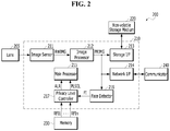
- FIG. 2 is a block diagram of an exemplary embodiment of a video capturing system constructed according to the principles of the invention.
- the video capturing system 200 such as the camera 110 of FIG. 1 includes a lens 205, a video processing device 210, a nonvolatile storage medium 220 and a memory 230.
- the video processing device 210 may capture a video, process the captured video, and perform various operations associated with the processed video. That is, the video processing device 210 is configured to perform operations of capturing the video and operations associated with the captured video.
- the video processing device 210 may operate in a privacy mode.
- the video processing device 210 may sense an image of a face ("face image") from the captured video, and enter the privacy mode based on the sensed face image.
- face image an image of a face
- the video processing device 210 may stop the video capturing operation performed during a normal mode and at least some of the operations associated with the capture video.
- the video processing device 210 may perform an additional operation associated with the capture video, for example, video distortion.
- the video processing device 210 can provide a plurality of privacy levels during the privacy mode.
- the video processing device 210 may select any one of the plurality of privacy levels based on the sensed face image.
- the video capturing operation and the operations associated with the captured video are selectively stopped and/or controlled according to the selected privacy level.
- the video processing device 210 may include an image sensor 211, an image processor 212, a storage interface (I/F) 213, a network I/F 214, a main processor 215, a face detector 216 and a privacy level controller 217.
- the image sensor 211 is connected to the lens 205.
- the image sensor 211 may operate in response to a control signal of the main processor 215.
- the image sensor 211 is configured to convert an optical signal received through the lens 205 into an electrical signal, and generate a raw image RWIMG by digitalizing the electrical signal.
- the image sensor 21 may include an analog-digital converter.
- the image processor 212 is connected to the image sensor 211.
- the image processor 212 may operate in response to a control signal of the main processor 215.
- the image processor 212 is configured to receive and process the raw image RWIMG to generate a processed image PRIMG. For example, the image processor 212 may adjust the size of the raw image RWIMG, adjust the resolution of the raw image RWIMG, or perform various algorithms for other necessary processes.
- the storage I/F 213 interfaces the nonvolatile storage medium 220 and the video processing device 210.
- the storage I/F module 213 may operate in response to a control signal of the main processor 215.
- the storage I/F 213 module may receive the processed image PRIMG, and write the processed image PRIMG to the nonvolatile storage medium 220.
- the network I/F 214 module interfaces between a communicator 240 (or transceiver) and the video processing device 210.
- the network I/F 214 module may operate in response to a control signal of the main processor 215.
- the network I/F 214 module may receive the processed image PRIMG and control the communicator 240 to transmit the processed image PRIMG to an external device such as the cloud database 130 and/or the user terminal 140 of FIG. 1 through the network 105 of FIG. 1 .
- the communicator 240 may transmit and receive signals between the video capturing system 200 and other devices through the network 105.
- the main processor 215 controls overall operations of the video capturing system 200.
- the main processor 215 may control the image sensor 211, the image processor 212, the storage I/F 213, the network I/F 214, the face detector 216 and the privacy level controller 217.
- the main processor 215 may control overall operations of the video capturing system 200 by executing software and/or firmware.
- Such software and/or firmware may be loaded to an internal memory of the main processor 215 and/or an external memory, such as the memory 230, from the non-volatile storage medium 220, and may executed by the main processor 215.
- the main processor 215 controls transitions between the normal mode and the privacy mode of the video processing device 210. Furthermore, the main processor 215 may control operations of capturing the video and operations associated with the captured video, such that the operations can be selectively performed according to the selected privacy level.
- the video capturing operation may be performed by the image sensor 211 and the main processor 215, and the operations associated with the captured video may be performed by the image processor 212, the storage I/F 213, the network I/F 214 and the main processor 215.
- the face detector 216 is connected to the image processor 212.
- the face detector 216 may operate in response to a control signal of the main processor 215.
- the face detector 216 receives the processed image PRIMG provided by the image processor 212.
- the face detector 216 is configured to sense a face included in the processed image (PRIMG), and provide face image information set FI according to the sensing result.
- the face detector 216 may detect an area including the face image in the processed image PRIMG to acquire and/or store the detected face image, and provide feature information of the detected face image, for example, feature points as the face image information set FI.
- the privacy level controller 217 is connected to the face detector 216.
- the privacy level controller 217 may operate in response to a control signal of the main processor 215.
- the privacy level controller 217 receives the face image information set FI from the face detector 216, and receives first to n-th reference image information sets RFI1 to RFIn from the memory 230, where n is an integer larger than or equal to 2.
- the first to n-th reference image information sets RFI1 to RFIn stored in the memory 230 may correspond to first to n-th reference images, respectively.
- the first to n-th reference images may be provided by a user selection, and the first to n-th reference image information sets RFI1 to RFIn may be acquired from the first to n-th reference images.
- Each of the first to n-th reference image information sets RFI1 to RFIn may include feature information of the corresponding reference image.
- the first to n-th reference image information sets RFI1 to RFIn may be generated by the face detector 216 and stored in the memory 230.
- a storage medium such as the memory 230 may be implemented in the form of a memory device or system which is known or developed in this field, and configured to store the first to n-th reference image information sets RFI1 to RFIn.
- the memory 230 may further store privacy levels associated with the first to n-th reference image information sets RFI1 to RFIn, respectively.
- the memory 230 may store privacy level information indicating which privacy level corresponds to each of the first to n-th reference image information sets RFI1 to RFIn.
- the first to n-th reference image information sets RFI1 to RFIn and the privacy levels may be stored in the nonvolatile storage medium 220, and loaded to the memory 230 by the main processor 215.
- the first to n-th reference image information sets RFI1 to RFIn and the privacy levels, which are loaded in the memory 230, may be provided to the privacy level controller 217.
- the privacy level controller 217 is configured to compare the face image information set FI to the first to n-th reference image information sets RFI1 to RFIn, and report the comparison result to the main processor 215.
- the privacy level controller 217 may enable an alarm signal ALR when a reference image information set matches the face image information set FI is present in the first to n-th reference image information sets RFI1 to RFIn.
- the privacy level controller 217 may disable the alarm signal ALR when there is no reference image information set matched with the face image information set FI.
- the main processor 215 may generate event information in response to the disabled alarm signal ALR, and transmit the generated event information to the event management server 120 through the network I/F 214. For example, when a stranger is captured, a reference image information set matched with the face image information set FI may not be present. In this case, event information may be generated.
- the privacy level controller 217 may select one of the privacy levels according to the reference image information set matched with the face image information set FI, among the first to n-th reference image information sets RFI1 to RFIn, and may report the selected privacy level (PLSEL) to the main processor 215.
- the privacy level controller 217 selects a privacy level corresponding to the matched reference image information set.
- the privacy level corresponding to each of the reference image information sets may be decided by a user input when the corresponding reference image is registered.
- a privacy level corresponding to a first user may be the highest level
- a privacy level corresponding to a second user may be the lowest level
- a privacy level corresponding to a third user may be the middle level therebetween.
- the main processor 215 may control the video processing device 210 or the video capturing system 200 according to the selected privacy level.
- the operations performed by the video processing device 210 or the video capturing system 200 may be changed according to the selected privacy level.
- the main processor 215 may control the image sensor 211 to stop capturing a video.
- video streaming and video recording may not be performed.
- all of the video capturing functions provided by the video capturing system 200 may be stopped.
- the main processor 215 may control the components of the video capturing system 200 to visually inform the user that the video capturing is not performed.
- the main processor 215 may control the lens 205 to face a different direction, when the first privacy level is selected. Thus, the user may visually recognize that the video capturing is not performed.
- the main processor 215 may control the light emitting device to stop emitting light or emit a different color of light, when the first privacy level is selected.
- the user may visually recognize that video capturing is not performed.
- a variety of event types may be defined, the event types including motion sensing, voice sensing, face sensing, body sensing, fire sensing, crying sound sensing, gunfire sound sensing, shock sound sensing and the like.
- the main processor 215 may generate event information, and store the generated event information in the event management server 120 through the network I/F 214.
- the operations for generating the event information may also be stopped.
- the main processor 215 may capture a video, but stop the operation of transferring the captured video to an external device such as the cloud database 130 of FIG. 1 through the network I/F 214.
- the main processor 215 may sense an event, and store the corresponding video in the nonvolatile storage medium 220 through the storage I/F 213 when the event is sensed. At this time, the main processor 215 may not report the occurrence of the event to the user terminal 140 of FIG. 1 .
- the main processor 215 may capture a video, but stop the operation of storing the captured video in any device. For example, the main processor 215 may stop the operation of storing the captured video in the nonvolatile storage medium 220 and the operation of storing the captured video in an external device through the network I/F 214. In the case where the operation of storing the captured video is performed in response to the event, the operation of sensing the event may also be stopped. At this time, the main processor 215 may provide the captured video to the external device in a streaming manner.
- exemplary embodiments of operations for each privacy level are not limited to the above-described examples.
- the operations performed by the video processing device 210 or the video capturing system 200 may be modified in various manners, and therefore the operations controlled at the respective privacy levels may also be changed.
- the video processing device 210 may operate in the privacy mode based on a sensed face image. Compared to the case in which the entry to the privacy mode is controlled by a user input, the video processing device 210 may automatically operate in the privacy mode when a face image matches a reference face image, thereby improving video capturing system and/or network resources, performance and convenience.
- the video processing device 210 may selectively control the operations of capturing the video and the operations associated with captured videos, according to the selected privacy level.
- a user may select a privacy level corresponding to the desired reference image, and the operations of the video processing device 210 may be controlled according to which privacy level is selected. Since the variety of privacy levels that cause the video processing device 210 to control the operations may improve the user convenience, better allocate the use, availability and speed of network resources and may solve various issues associated with the video adaptively for each user. For example, the various technical issues that may be solved include the possibility that the captured video will be leaked, the finitude of the storage space for storing captured videos, and an excessive amount of event information accumulated in the event management server 120.
- the face detector 216 and the privacy level controller 217 are illustrated as being distinguished from the main processor 215.
- exemplary embodiments are not limited thereto.
- the face detector 216 and the privacy level controller 217 may be integrated into the main processor 215, and the main processor 215 may perform the functions of the face detector 216 and the privacy level controller 217.
- the face detector 216 and the privacy level controller 217 may be implemented through software, hardware, firmware or combinations thereof.
- the main processor 215 may provide the functions of the face detector 216 and the privacy level controller 217 by loading the corresponding software modules to a working memory such as the memory 230 and executing the loaded software modules.
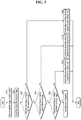
- FIG. 3 is a flowchart of an exemplary embodiment of a method of providing a privacy mode based on a captured image according to the principles of the invention.
- an image captured in the normal mode is received in step S110.
- a face image is detected from the captured image.
- the captured image may be processed according to predetermined methods, and an area including the face image in the processed image may be detected.
- the face image may be sensed through at least one of various methods such as a Gabor filter, PCA (Principal Component Analysis), FDA (Fisher Discriminant Analysis), ICA (Independent Component Analysis), LBP (local Binary Feature) and SVM (Support Vector Machine).
- step S130 the video capturing system determines whether the detected face image is matched with a first reference image.
- the video capturing system may determine whether feature information (for example, feature points) of the detected face image is matched with a reference image information set of the first reference image.
- step S160 is performed. Otherwise, step S140 is performed.
- the detected face image may be compared to other reference images.
- the video capturing system determines whether the detected face image is matched with a second reference image. When the detected face image is matched with the second reference image, step S170 is performed. Otherwise, step S150 is performed.
- step S150 the video capturing system determines whether the detected face image is matched with a third reference image. When the detected face image is matched with the third reference image, step S180 is performed. Otherwise, step S190 is performed.
- the video processing device 210 of FIG. 2 When the detected face image is matched with any one of the first to third reference images, the video processing device 210 of FIG. 2 operates in the privacy mode. According to which reference image is matched with the detected face image, the corresponding privacy level is selected.
- step S160 the video processing device 210 is controlled to operate at the first privacy level.
- step S170 the video processing device 210 is controlled to operate at the second privacy level.
- step S180 the video processing device 210 is controlled to operate at the third privacy level.
- event information may be generated when the detected face image is not matched with the first to third reference images.
- the generated event information may be transmitted to the event management server 120 of FIG. 1 , and the user terminal 140 of FIG. 1 may access the event management server 120 to receive the event information.
- FIG. 4 is a flowchart of another exemplary embodiment of a method of providing the privacy mode based on the captured image.
- a captured image is received in step S210.
- a face image is detected from the captured image.
- Steps S210 and S220 may be performed in the same manner as steps S110 and S120 of FIG. 3 . Thus, the duplicated descriptions are omitted for clarity and conciseness.
- step S230 the video capturing system determines whether two or more face images are detected from the captured image. When two or more face images are detected from the captured image, step S240 is performed. Otherwise, step S130 of FIG. 3 may be performed
- step S240 the video capturing system determines whether each of the detected face images is matched with the reference images.
- Feature information may be extracted from each of the detected face images, and compared to the previously stored reference image information sets (see RFI1 to RFIn of FIG. 2 ).
- step S250 step S260 or S270 is performed according to whether the two or more face images are matched with the reference images.
- the privacy level having the highest priority is selected among privacy levels corresponding to the matched reference images.
- the priorities of the privacy levels may be decided in advance. For example, the first privacy level has the highest priority, the second privacy level has a lower priority than the first privacy level, and the third privacy level has a lower priority than the second privacy level.
- step S270 the privacy level corresponding to the matched reference image is selected.
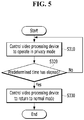
- FIG. 5 is a flowchart of an exemplary embodiment of a method of returning from the privacy mode to a normal mode.
- the video processing device 210 is controlled to operate in the privacy mode in step S310.
- the main processor 215 may control the video processing device 210 according to the selected privacy level.
- step S320 the video capturing system 200 determines whether a predetermined time has elapsed after the video processing device 210 started to operate in the privacy mode.
- the video capturing system 200 may further include a timer, and determine whether a predetermined time has elapsed using the timer.
- step S330 the video processing device 210 is controlled to return to the normal mode. That is, the privacy mode is ended.
- the video processing device 210 may operate at the selected privacy level for 30 minutes or one hour, and then return to the normal mode.
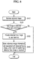
- FIG. 6 is a flowchart of an exemplary embodiment of a method of providing reference image information sets.
- Step S410 a captured image is received in step S410.
- step S430 is performed.
- Step S420 may be performed by the video capturing system 200.
- the detecting of the face image may be performed by the face detector 216 of FIG. 2 .
- step S420 may be performed by the user terminal 140 of FIG. 1 .
- the user terminal 140 may receive the captured image from the video capturing system 200 and may further include a software or hardware module for detecting a face image from the received image.
- the detected face image may be provided to the user terminal 140.
- the main processor 215 may transmit the detected face image to the user terminal 140 through the network I/F 214, and the user terminal 140 may display the received face image.
- the user of the user terminal 140 may provide an input of registering (or selecting) the detected face image. At this time, the user may further provide an input of deciding a privacy level corresponding to the detected face image.
- step S440 feature information associated with the detected face image is stored as a reference image information set when the input of registering the detected face image is received from the user terminal 140.
- the input of registering the detected face image may be received from the user terminal 140 through the communicator 240.
- the main processor 215 may generate feature information associated with the detected face image and store the generated feature information as a reference image information set in the nonvolatile storage medium 220, in response to the input of registering the detected face image.
- the input of registering the detected face image may further include data on the decided privacy level.
- the decided privacy level may be further stored in the nonvolatile storage medium 220 in association with the reference image information set.
- FIG. 7 is a flowchart of an exemplary embodiment of a method of determining a privacy level corresponding to each set of reference image information.
- step S510 a captured image is received in step S510. According to whether a face image is detected from the captured image in step S520, step S530 is performed.
- step S530 the video capturing system determines whether a reference image information set matched with the detected face image is present in the previously stored reference image information sets (see RFI1 to RFIn of FIG. 2 ).
- Step S530 may be performed by the main processor 215, the face detector 216, and/or the privacy level controller 217.
- step S540 is performed. Otherwise, step S550 is performed.
- step S540 the reference image information set associated with the detected face image is stored.
- the main processor 215 may generate feature information associated with the detected face image and store the generated feature information as a reference image information set in the nonvolatile storage medium 220.
- step S550 a count value corresponding to the reference image information set is increased.
- step S560 a privacy level corresponding to the reference image information set is decided according to the count value. Steps S550 and S560 may be performed by the main processor 215.
- Persons or objects which are frequently captured may be the main user of the space where the video capturing system 200 is installed, or users related to the main user.
- the video capturing system 200 can estimate the main user or the users related to the main user, decide the privacy levels according to the appearance frequencies of the main user and the users, and apply the privacy levels when they are captured without user inputs such as selecting a reference image and setting the privacy level of the reference image. Therefore, it is possible to provide the video capturing system 200 capable of improving camera and network performance and convenience, and the operating method thereof.
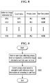
- FIG. 8 is a table showing an exemplary list of information associated with the reference image information sets.
- a count value and a privacy level which correspond to a reference image information set may be decided through the embodiment of FIG. 7 .
- the count value and the privacy level may be stored in the nonvolatile storage medium 220.
- the first reference image information set RFI1 may have a first count value CNT1 and thus corresponds to a first privacy level PL1.
- the second reference image information set RFI2 may have a second count value CNT2 and a third privacy level PL3, and the n-th reference image information set RFIn may have an n-th count value CNTn and the second privacy level PL2.
- the first privacy level PL1 may be stored in association with the corresponding reference image information set.
- the second privacy level PL2 may be stored in association with the corresponding reference image information set.
- the third privacy level PL3 may be stored in association with the corresponding reference image information set. As such, the privacy level corresponding to each of the first to n-th reference image information sets may be determined depending on the count value.
- Table of FIG. 8 may further include a user designation field indicating whether the privacy level corresponding to each of the reference image information sets has been designated by a user.
- the user designation fields of the first, second and n-th reference image information sets RFI1, RFI2 and RFIn are stored as 'NONE' as the privacy levels thereof have been decided not by a user, but by the video capturing system 200 through the embodiments of FIG. 7 .
- FIG. 9 is a flowchart of another exemplary embodiment of the method of determining a privacy level corresponding to each set of reference image information.
- a user input indicating a privacy level corresponding to a reference image information set is received from the user terminal 140 of FIG. 1 , in step S610.
- a user may access the video capturing system 200 to check a face image corresponding to each of the reference image information sets, and provide a user input of deciding the corresponding privacy level through the user terminal 140.
- the user may check a face image corresponding to the second reference image information set RFI2 of FIG. 8 , and set a privacy level corresponding to the face image to the first privacy level.
- step S620 the privacy level stored in association with the reference image information set is corrected according to a user input.
- the main processor 215 may change the privacy level corresponding to the second reference image information set RFI2 from the third privacy level PL3 to the first privacy level PL1 according to the user input.
- the user designation field is changed from "NONE" to "YES", for example.
- FIG. 10 is a block diagram of an exemplary embodiment of a computer system suitable for implementing the video capturing system of FIG. 2 .
- the computer system 1000 may include a bus 1001, a main processor 1002, an internal memory 1003, an image processor 1004, a storage I/F 1005, a network I/F 1006, a nonvolatile storage medium 1007, a communicator 1008, an image sensor 1009, a lens 1010, a motor 1011, a motor controller 1012 and an external memory 1013.
- the bus 1001 connects the components of the computer system 1000 for communication of data, signals and information.
- the main processor 1002 may be at least one of a general purpose processor and a dedicated processor, and control overall operations of the computer system 1000.
- the main processor 1002 may perform the functions of the main processor 215 described with reference to FIG. 2 .
- the functions of the face detector 216 and the privacy level controller 217 described with reference to FIG. 2 may be performed by the main processor 1002.
- the main processor 1002 may load a face detection module and a privacy level control module to the internal memory 1003, and execute the loaded modules to perform the functions of the face detector 216 and the privacy level controller 217.
- the face detection module may include a software module that provides the function of the face detector 2016 when executed by the main processor 1002
- the privacy level control module may include a software module that provides the function of the privacy level controller 217 when executed by the main processor 1002.
- the internal memory 1003 may store computer programs and/or commands which are to be executed by the main processor 1002.
- the internal memory 1003 is provided as a working memory of the main processor 1002.
- the internal memory 1003 may include a RAM (Random Access Memory), a ROM (Read Only Memory) or one or more combinations of various types of computer readable media.
- the internal memory 1003 may further perform the function of the memory 230 described with reference to FIG. 2 .
- the image processor 1004, the storage I/F 1005, the network I/F 1006, the nonvolatile storage medium 1007 and the communicator 1008 are configured in the same manner as the image processor 212, the storage I/F 213, the network I/F 214, the nonvolatile storage medium 220 and the communicator 240 described with reference to FIG. 2 .
- the image sensor 1009 and the lens 1010 are configured in the same manner as the image sensor 211 and the lens 205 described with reference to FIG. 2 .
- the motor 1011 is configured to drive the lens 1010, and the motor controller 1012 is configured to control the operation of the motor 1011 in response to a control signal of a semiconductor chip CHIP.
- the main processor 1002, the internal memory 1003 and the image processor 1004 may be integrated into one semiconductor chip CHIP.
- the semiconductor chip CHIP may further include the storage I/F 1005 and the network I/F 1006.
- the computer system 1000 may further include an external memory 1013.
- the external memory 1013 may provide an additional storage space to the components within the computer system 1000, such as the main processor 1002.
- the external memory 1013 may be attached to and detected from the computer system 1000.
- the processor 1002 may use the external memory 1013 as a working memory with the internal memory 1003.
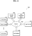
- FIG. 11 is a block diagram of an exemplary embodiment of a network system including a plurality of cameras constructed according to the principles of the invention.
- the network system 2000 may include a network 2005, first to k-th cameras 2110 to 21k0, a computer device 2050, an event management server 2200, a cloud database 2300 and a user terminal 2400.
- the event management server 2200, the cloud database 2300, and the user terminal 2400 are configured in the same manner as the event management server 120, the cloud database 130 and the user terminal 140 of FIG. 1 .
- the duplicated descriptions are omitted for clarity and conciseness.
- a plurality of cameras such as the first to k-th cameras 2110 to 21k0 may be installed in specific areas such as the inside of a building, the outside of a building and a park. Furthermore, the computer device 2050 communicating with the first to k-th cameras 2110 to 21k0 may be provided. The computer device 2050 may control the first to k-th cameras 2110 to 21k0. In some exemplary embodiments, the computer device 2050 may include and execute dedicated software for controlling the first to k-th cameras 2110 to 21k0. In some exemplary embodiments, the computer device 2050 may be installed at a position adjacent to the first to k-th cameras 2110 to 21k0. In some embodiments, the computer device 2050 may include at least one of wired and wireless communication functions to communicate with the first to k-th cameras 2110 to 21k0 through the network 2005.
- At least one of the first to k-th cameras 2110 to 21k0 may be the video capturing system 200 of FIG. 2 , and thus perform the operations of the video capturing system 200 described with reference to FIGS. 3 to 9 .
- the first camera 2110 of the first to k-th cameras 2110 to 21k0 will be assumed to function as the video capturing system 200 of FIG. 2 , for convenience of description.
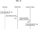
- FIG. 12 is a flowchart of an exemplary embodiment of a method of providing a privacy mode for the plurality of cameras of FIG. 11 .
- the first camera 2110 selects a privacy level in step S710.
- the first camera 2110 may control a video capturing operation and operations associated with a captured video, according to the selected privacy level.
- step S720 the first camera 2110 reports the selected privacy level to the computer device 2050.
- step S730 the computer device 2050 transmits control signals to operate the second to k-th cameras 2120 to 21k0 in the privacy mode, in response to the reception of the selected privacy level.
- the computer device 2050 may report the selected privacy level to the second to k-th cameras 2120 to 21k0.
- the second to k-th cameras 2120 to 21k0 enter the privacy mode.
- the second to k-th cameras 2120 to 21k0 each may operate in the privacy mode, , and may control the video capturing operation and the operations associated with the captured video in the same manner as the first camera 2110 according to the selected privacy level received through the computer device 2050.
- a camera of the first to k-th cameras 2110 to 21k0 including resources required for selecting one of a plurality of privacy levels may enable the other cameras to operate in the privacy mode even though the other cameras do not include such resources.
- the first camera 2110 includes a processor having relatively high performance and a memory having a relatively large storage space and each of the second to k-th cameras 2120 to 21k0 includes a processor having lower performance and a memory having a smaller storage space than the first camera 2110, the second to k-th cameras 2120 to 21k0 may enter the privacy mode depending on entry into the privacy mode at the first camera 2110, and may operate under the common privacy level selected by the first camera 2110.
Landscapes
- Engineering & Computer Science (AREA)
- Multimedia (AREA)
- Signal Processing (AREA)
- Theoretical Computer Science (AREA)
- Physics & Mathematics (AREA)
- Human Computer Interaction (AREA)
- General Physics & Mathematics (AREA)
- Oral & Maxillofacial Surgery (AREA)
- General Health & Medical Sciences (AREA)
- Health & Medical Sciences (AREA)
- Data Mining & Analysis (AREA)
- Life Sciences & Earth Sciences (AREA)
- Evolutionary Computation (AREA)
- General Engineering & Computer Science (AREA)
- Evolutionary Biology (AREA)
- Computer Vision & Pattern Recognition (AREA)
- Bioinformatics & Computational Biology (AREA)
- Bioinformatics & Cheminformatics (AREA)
- Artificial Intelligence (AREA)
- Studio Devices (AREA)
- Closed-Circuit Television Systems (AREA)
Applications Claiming Priority (2)
| Application Number | Priority Date | Filing Date | Title |
|---|---|---|---|
| KR20180053788 | 2018-05-10 | ||
| KR1020190031219A KR102628414B1 (ko) | 2018-05-10 | 2019-03-19 | 프라이버시 모드를 지원하는 영상 촬영 시스템 및 네트워크 시스템 |
Publications (3)
| Publication Number | Publication Date |
|---|---|
| EP3576012A2 true EP3576012A2 (fr) | 2019-12-04 |
| EP3576012A3 EP3576012A3 (fr) | 2020-03-25 |
| EP3576012B1 EP3576012B1 (fr) | 2023-11-22 |
Family
ID=66589199
Family Applications (1)
| Application Number | Title | Priority Date | Filing Date |
|---|---|---|---|
| EP19173813.7A Active EP3576012B1 (fr) | 2018-05-10 | 2019-05-10 | Système de capture vidéo et système de réseau pour la prise en charge du mode confidentiel |
Country Status (2)
| Country | Link |
|---|---|
| US (2) | US20190349517A1 (fr) |
| EP (1) | EP3576012B1 (fr) |
Families Citing this family (5)
| Publication number | Priority date | Publication date | Assignee | Title |
|---|---|---|---|---|
| US11250536B2 (en) * | 2019-09-11 | 2022-02-15 | International Business Machines Corporation | Image capture prevention |
| CN111464679B (zh) * | 2020-04-09 | 2021-05-25 | Oppo广东移动通信有限公司 | 电子设备及其监控方法 |
| KR20220029212A (ko) | 2020-09-01 | 2022-03-08 | 삼성전자주식회사 | 전자 장치 및 그 제어 방법 |
| SE544751C2 (en) * | 2021-01-26 | 2022-11-01 | Assa Abloy Ab | Enabling training of an ml model for monitoring states or events of a person |
| CN118077190A (zh) * | 2022-05-30 | 2024-05-24 | 俏丽时有限公司 | 能够进行选择性数据传输以用于隐私保护的相机 |
Family Cites Families (62)
| Publication number | Priority date | Publication date | Assignee | Title |
|---|---|---|---|---|
| US7068309B2 (en) * | 2001-10-09 | 2006-06-27 | Microsoft Corp. | Image exchange with image annotation |
| US7221865B2 (en) * | 2002-11-25 | 2007-05-22 | Olympus Corporation | Electronic camera, information device and portable information apparatus |
| JP4568009B2 (ja) * | 2003-04-22 | 2010-10-27 | パナソニック株式会社 | カメラ連携による監視装置 |
| US8493443B2 (en) * | 2005-01-04 | 2013-07-23 | Hewlett-Packard Development Company, L.P. | Methods and apparatus for location determination and asserting and maintaining privacy |
| US8253770B2 (en) * | 2007-05-31 | 2012-08-28 | Eastman Kodak Company | Residential video communication system |
| US10169646B2 (en) * | 2007-12-31 | 2019-01-01 | Applied Recognition Inc. | Face authentication to mitigate spoofing |
| US8180112B2 (en) * | 2008-01-21 | 2012-05-15 | Eastman Kodak Company | Enabling persistent recognition of individuals in images |
| US20100124363A1 (en) * | 2008-11-20 | 2010-05-20 | Sony Ericsson Mobile Communications Ab | Display privacy system |
| US8576282B2 (en) * | 2008-12-12 | 2013-11-05 | Honeywell International Inc. | Security system with operator-side privacy zones |
| AU2010221722A1 (en) * | 2009-02-06 | 2011-08-18 | Oculis Labs, Inc. | Video-based privacy supporting system |
| JP5251817B2 (ja) * | 2009-09-30 | 2013-07-31 | 沖電気工業株式会社 | 画像処理装置および画像処理方法 |
| US8649573B1 (en) * | 2010-06-14 | 2014-02-11 | Adobe Systems Incorporated | Method and apparatus for summarizing video data |
| JP5637633B2 (ja) * | 2010-07-06 | 2014-12-10 | パナソニック インテレクチュアル プロパティ コーポレーション オブアメリカPanasonic Intellectual Property Corporation of America | 画像配信装置 |
| US8826446B1 (en) * | 2011-01-19 | 2014-09-02 | Google Inc. | System and method for applying privacy settings to a plurality of applications |
| US9317530B2 (en) * | 2011-03-29 | 2016-04-19 | Facebook, Inc. | Face recognition based on spatial and temporal proximity |
| KR101703931B1 (ko) * | 2011-05-24 | 2017-02-07 | 한화테크윈 주식회사 | 감시 시스템 |
| KR101936802B1 (ko) * | 2012-07-20 | 2019-01-09 | 한국전자통신연구원 | 얼굴인식 기반의 개인정보보호 장치 및 방법 |
| US9317721B2 (en) * | 2012-10-31 | 2016-04-19 | Google Inc. | Privacy aware camera and device status indicator system |
| US9124762B2 (en) * | 2012-12-20 | 2015-09-01 | Microsoft Technology Licensing, Llc | Privacy camera |
| KR101875137B1 (ko) * | 2013-03-26 | 2018-07-06 | 한화에어로스페이스 주식회사 | 프라이버시 마스크 처리 방법 및 장치 |
| US9104886B1 (en) * | 2013-06-26 | 2015-08-11 | Amazon Technologies, Inc. | Automated privacy control |
| US10346624B2 (en) * | 2013-10-10 | 2019-07-09 | Elwha Llc | Methods, systems, and devices for obscuring entities depicted in captured images |
| US9288452B2 (en) * | 2013-11-21 | 2016-03-15 | Panasonic Intellectual Property Management Co., Ltd. | Apparatus for controlling image capturing device and shutter |
| US9231977B2 (en) * | 2013-12-23 | 2016-01-05 | Nokia Technologies Oy | Method and apparatus for providing collaborative privacy policies for a shared device |
| EP3119075A4 (fr) * | 2014-03-10 | 2017-11-15 | Sony Corporation | Appareil de traitement d'informations, support d'informations et procédé de commande |
| US10182213B2 (en) * | 2014-06-02 | 2019-01-15 | Vivint, Inc. | Security camera privacy shutter |
| US10679671B2 (en) * | 2014-06-09 | 2020-06-09 | Pelco, Inc. | Smart video digest system and method |
| US10306125B2 (en) * | 2014-10-09 | 2019-05-28 | Belkin International, Inc. | Video camera with privacy |
| EP2981063B1 (fr) * | 2014-07-31 | 2020-03-04 | Samsung Electronics Co., Ltd | Procédé de modification d'image présentant un élément restreint de photographie et dispositif destinés à mettre en oeuvre le procédé |
| US20160044039A1 (en) * | 2014-08-07 | 2016-02-11 | Alcatel Lucent | Privacy-aware personal data store |
| CN104166604A (zh) * | 2014-08-15 | 2014-11-26 | 小米科技有限责任公司 | 视频备份方法和装置 |
| US10602054B2 (en) * | 2014-09-12 | 2020-03-24 | Microsoft Technology Licensing, Llc | Video capture with privacy safeguard |
| US9179105B1 (en) * | 2014-09-15 | 2015-11-03 | Belkin International, Inc. | Control of video camera with privacy feedback |
| US20170255820A1 (en) * | 2014-09-16 | 2017-09-07 | Jiwen Liu | Identification of individuals in images and associated content delivery |
| CN105574467A (zh) * | 2014-10-09 | 2016-05-11 | 多媒体影像解决方案有限公司 | 用于具有人物辨识的相机的隐私 |
| KR101849365B1 (ko) * | 2014-11-05 | 2018-04-16 | 한화테크윈 주식회사 | 영상 처리 장치 및 방법 |
| JP6367102B2 (ja) * | 2014-12-09 | 2018-08-01 | 株式会社キーエンス | 監視システム |
| WO2016210305A1 (fr) * | 2015-06-26 | 2016-12-29 | Mobile Video Corporation | Caméra mobile et système doté de fonctions automatisées et de modes de fonctionnement |
| US10523639B2 (en) * | 2015-10-30 | 2019-12-31 | International Business Machines Corporation | Privacy preserving wearable computing device |
| US20170148487A1 (en) * | 2015-11-25 | 2017-05-25 | Dell Products L.P. | Video Manipulation for Privacy Enhancement |
| US10546185B2 (en) * | 2015-12-01 | 2020-01-28 | Casio Computer Co., Ltd. | Image processing apparatus for performing image processing according to privacy level |
| WO2017129804A1 (fr) * | 2016-01-29 | 2017-08-03 | Kiwisecurity Software Gmbh | Procédés et appareil permettant d'utiliser une analytique vidéo pour détecter des régions en vue d'une protection de la confidentialité dans des images provenant de caméras mobiles |
| US20170289504A1 (en) * | 2016-03-31 | 2017-10-05 | Ants Technology (Hk) Limited. | Privacy Supporting Computer Vision Systems, Methods, Apparatuses and Associated Computer Executable Code |
| JP2017201753A (ja) * | 2016-05-06 | 2017-11-09 | キヤノン株式会社 | ネットワークシステム及びその制御方法 |
| JP6393360B2 (ja) * | 2016-05-11 | 2018-09-19 | パナソニック インテレクチュアル プロパティ コーポレーション オブ アメリカPanasonic Intellectual Property Corporation of America | 撮影制御方法、撮影制御システム及び撮影制御サーバ |
| EP3465560A1 (fr) * | 2016-06-07 | 2019-04-10 | Koninklijke Philips N.V. | Commande de réglage de la confidentialité d'un capteur |
| US10339775B2 (en) * | 2016-06-21 | 2019-07-02 | BroadPath, Inc. | Method for collecting and sharing live video feeds of employees within a distributed workforce |
| US10789910B2 (en) * | 2016-07-20 | 2020-09-29 | Dell Products, L.P. | Information handling system with dynamic privacy mode display |
| US20180035074A1 (en) * | 2016-07-28 | 2018-02-01 | Melvin L. Barnes, Jr. | System, Method and Computer Program Product for Processing Image Data |
| EP3504071A4 (fr) * | 2016-08-26 | 2020-01-15 | Netradyne Inc. | Enregistrement de vidéo d'un opérateur et d'un champ visuel environnant |
| US10460171B2 (en) * | 2016-08-31 | 2019-10-29 | Facebook, Inc. | Systems and methods for processing media content that depict objects |
| KR102614012B1 (ko) * | 2016-11-08 | 2023-12-14 | 한화비전 주식회사 | 영상처리장치 및 그의 영상제공방법 |
| US10318758B2 (en) * | 2016-12-14 | 2019-06-11 | Blackberry Limited | Selectable privacy modes |
| US10244161B2 (en) * | 2017-01-13 | 2019-03-26 | Microsoft Technology Licensing, Llc | Capturing and viewing private photos and videos |
| US20180278835A1 (en) * | 2017-03-21 | 2018-09-27 | Honeywell International Inc. | Systems and methods for enabling dynamic privacy zones in the field of view of a security camera based on motion detection |
| KR20180113787A (ko) * | 2017-04-07 | 2018-10-17 | 삼성전자주식회사 | 디스플레이 장치 및 그 제어 방법 |
| US10861267B2 (en) * | 2017-08-04 | 2020-12-08 | James Andrew Aman | Theme park gamification, guest tracking and access control system |
| US10805521B2 (en) * | 2017-09-05 | 2020-10-13 | Facebook, Inc. | Modifying capture of video data by an image capture device based on video data previously captured by the image capture device |
| US10754996B2 (en) * | 2017-09-15 | 2020-08-25 | Paypal, Inc. | Providing privacy protection for data capturing devices |
| US10586070B2 (en) * | 2017-11-14 | 2020-03-10 | International Business Machines Corporation | Privacy protection in captured image for distribution |
| US10740617B2 (en) * | 2017-12-19 | 2020-08-11 | Intel Corporation | Protection and recovery of identities in surveillance camera environments |
| US10509912B2 (en) * | 2017-12-27 | 2019-12-17 | Intel Corporation | Privacy assembly for image capture device |
-
2019
- 2019-05-03 US US16/402,721 patent/US20190349517A1/en not_active Abandoned
- 2019-05-10 EP EP19173813.7A patent/EP3576012B1/fr active Active
-
2023
- 2023-05-27 US US18/324,959 patent/US12361749B2/en active Active
Also Published As
| Publication number | Publication date |
|---|---|
| US12361749B2 (en) | 2025-07-15 |
| US20230306780A1 (en) | 2023-09-28 |
| US20190349517A1 (en) | 2019-11-14 |
| EP3576012B1 (fr) | 2023-11-22 |
| EP3576012A3 (fr) | 2020-03-25 |
Similar Documents
| Publication | Publication Date | Title |
|---|---|---|
| US12361749B2 (en) | Image capturing system and network system to support privacy mode | |
| KR102524498B1 (ko) | 듀얼 카메라를 포함하는 전자 장치 및 듀얼 카메라의 제어 방법 | |
| US8373755B2 (en) | Network camera and system and method for operating the network camera and system | |
| CN109644229B (zh) | 用于控制相机的方法及其电子设备 | |
| KR102237973B1 (ko) | 오디오/비디오 레코딩 및 통신 디바이스들로부터의 비디오 영상의 공유 | |
| CN110073654B (zh) | 控制设备、控制方法、计算机存储介质以及电子装置系统 | |
| US9912660B2 (en) | Apparatus for authenticating pairing of electronic devices and associated methods | |
| US20150142891A1 (en) | Anticipatory Environment for Collaboration and Data Sharing | |
| US20250317648A1 (en) | Low power object detection | |
| EP2840558B1 (fr) | Dispositif électronique pour communiquer avec des caméras externes | |
| KR20160038460A (ko) | 전자 장치와, 그의 제어 방법 | |
| EP2911088B1 (fr) | Procédé et appareil permettant de traiter des informations biométriques | |
| US10339777B2 (en) | Identifying an individual based on an electronic signature | |
| US9930479B2 (en) | Method, apparatus, and mobile terminal for collecting location information | |
| US11765469B2 (en) | Image capturing apparatus, device, control method, and computer-readable storage medium | |
| US10142334B2 (en) | Communicating apparatus, method, and communicating system | |
| KR102628414B1 (ko) | 프라이버시 모드를 지원하는 영상 촬영 시스템 및 네트워크 시스템 | |
| CN113115460A (zh) | 时隙选择方法及相关设备 | |
| US10896515B1 (en) | Locating missing objects using audio/video recording and communication devices | |
| US10451838B2 (en) | Electronic device and method for autofocusing | |
| US20140373185A1 (en) | Anti-theft Method and Computer System thereof | |
| KR101971477B1 (ko) | 영상획득장치 및 영상처리장치 | |
| US11561908B2 (en) | Electronic device, processing proxy requesting method of electronic device, and information processing system | |
| US12557015B2 (en) | Saving battery usage on battery powered devices | |
| US20200134995A1 (en) | Home device |
Legal Events
| Date | Code | Title | Description |
|---|---|---|---|
| PUAI | Public reference made under article 153(3) epc to a published international application that has entered the european phase |
Free format text: ORIGINAL CODE: 0009012 |
|
| STAA | Information on the status of an ep patent application or granted ep patent |
Free format text: STATUS: THE APPLICATION HAS BEEN PUBLISHED |
|
| AK | Designated contracting states |
Kind code of ref document: A2 Designated state(s): AL AT BE BG CH CY CZ DE DK EE ES FI FR GB GR HR HU IE IS IT LI LT LU LV MC MK MT NL NO PL PT RO RS SE SI SK SM TR |
|
| AX | Request for extension of the european patent |
Extension state: BA ME |
|
| PUAL | Search report despatched |
Free format text: ORIGINAL CODE: 0009013 |
|
| AK | Designated contracting states |
Kind code of ref document: A3 Designated state(s): AL AT BE BG CH CY CZ DE DK EE ES FI FR GB GR HR HU IE IS IT LI LT LU LV MC MK MT NL NO PL PT RO RS SE SI SK SM TR |
|
| AX | Request for extension of the european patent |
Extension state: BA ME |
|
| RIC1 | Information provided on ipc code assigned before grant |
Ipc: G06K 9/00 20060101AFI20200215BHEP Ipc: H04W 12/02 20090101ALI20200215BHEP |
|
| STAA | Information on the status of an ep patent application or granted ep patent |
Free format text: STATUS: REQUEST FOR EXAMINATION WAS MADE |
|
| 17P | Request for examination filed |
Effective date: 20200921 |
|
| RBV | Designated contracting states (corrected) |
Designated state(s): AL AT BE BG CH CY CZ DE DK EE ES FI FR GB GR HR HU IE IS IT LI LT LU LV MC MK MT NL NO PL PT RO RS SE SI SK SM TR |
|
| STAA | Information on the status of an ep patent application or granted ep patent |
Free format text: STATUS: EXAMINATION IS IN PROGRESS |
|
| 17Q | First examination report despatched |
Effective date: 20210820 |
|
| REG | Reference to a national code |
Ref country code: DE Ref legal event code: R079 Free format text: PREVIOUS MAIN CLASS: G06K0009000000 Ipc: G06V0040160000 Ref document number: 602019041770 Country of ref document: DE |
|
| RIC1 | Information provided on ipc code assigned before grant |
Ipc: G06V 40/16 20220101AFI20230508BHEP |
|
| GRAP | Despatch of communication of intention to grant a patent |
Free format text: ORIGINAL CODE: EPIDOSNIGR1 |
|
| STAA | Information on the status of an ep patent application or granted ep patent |
Free format text: STATUS: GRANT OF PATENT IS INTENDED |
|
| INTG | Intention to grant announced |
Effective date: 20230619 |
|
| RAP3 | Party data changed (applicant data changed or rights of an application transferred) |
Owner name: HANWHA VISION CO., LTD. |
|
| GRAS | Grant fee paid |
Free format text: ORIGINAL CODE: EPIDOSNIGR3 |
|
| GRAA | (expected) grant |
Free format text: ORIGINAL CODE: 0009210 |
|
| STAA | Information on the status of an ep patent application or granted ep patent |
Free format text: STATUS: THE PATENT HAS BEEN GRANTED |
|
| AK | Designated contracting states |
Kind code of ref document: B1 Designated state(s): AL AT BE BG CH CY CZ DE DK EE ES FI FR GB GR HR HU IE IS IT LI LT LU LV MC MK MT NL NO PL PT RO RS SE SI SK SM TR |
|
| REG | Reference to a national code |
Ref country code: GB Ref legal event code: FG4D |
|
| REG | Reference to a national code |
Ref country code: CH Ref legal event code: EP |
|
| REG | Reference to a national code |
Ref country code: DE Ref legal event code: R096 Ref document number: 602019041770 Country of ref document: DE |
|
| REG | Reference to a national code |
Ref country code: IE Ref legal event code: FG4D |
|
| REG | Reference to a national code |
Ref country code: LT Ref legal event code: MG9D |
|
| REG | Reference to a national code |
Ref country code: NL Ref legal event code: MP Effective date: 20231122 |
|
| PG25 | Lapsed in a contracting state [announced via postgrant information from national office to epo] |
Ref country code: GR Free format text: LAPSE BECAUSE OF FAILURE TO SUBMIT A TRANSLATION OF THE DESCRIPTION OR TO PAY THE FEE WITHIN THE PRESCRIBED TIME-LIMIT Effective date: 20240223 |
|
| PG25 | Lapsed in a contracting state [announced via postgrant information from national office to epo] |
Ref country code: IS Free format text: LAPSE BECAUSE OF FAILURE TO SUBMIT A TRANSLATION OF THE DESCRIPTION OR TO PAY THE FEE WITHIN THE PRESCRIBED TIME-LIMIT Effective date: 20240322 |
|
| PG25 | Lapsed in a contracting state [announced via postgrant information from national office to epo] |
Ref country code: LT Free format text: LAPSE BECAUSE OF FAILURE TO SUBMIT A TRANSLATION OF THE DESCRIPTION OR TO PAY THE FEE WITHIN THE PRESCRIBED TIME-LIMIT Effective date: 20231122 |
|
| REG | Reference to a national code |
Ref country code: AT Ref legal event code: MK05 Ref document number: 1634556 Country of ref document: AT Kind code of ref document: T Effective date: 20231122 |
|
| PG25 | Lapsed in a contracting state [announced via postgrant information from national office to epo] |
Ref country code: NL Free format text: LAPSE BECAUSE OF FAILURE TO SUBMIT A TRANSLATION OF THE DESCRIPTION OR TO PAY THE FEE WITHIN THE PRESCRIBED TIME-LIMIT Effective date: 20231122 |
|
| PG25 | Lapsed in a contracting state [announced via postgrant information from national office to epo] |
Ref country code: AT Free format text: LAPSE BECAUSE OF FAILURE TO SUBMIT A TRANSLATION OF THE DESCRIPTION OR TO PAY THE FEE WITHIN THE PRESCRIBED TIME-LIMIT Effective date: 20231122 |
|
| PG25 | Lapsed in a contracting state [announced via postgrant information from national office to epo] |
Ref country code: ES Free format text: LAPSE BECAUSE OF FAILURE TO SUBMIT A TRANSLATION OF THE DESCRIPTION OR TO PAY THE FEE WITHIN THE PRESCRIBED TIME-LIMIT Effective date: 20231122 |
|
| PG25 | Lapsed in a contracting state [announced via postgrant information from national office to epo] |
Ref country code: NL Free format text: LAPSE BECAUSE OF FAILURE TO SUBMIT A TRANSLATION OF THE DESCRIPTION OR TO PAY THE FEE WITHIN THE PRESCRIBED TIME-LIMIT Effective date: 20231122 Ref country code: LT Free format text: LAPSE BECAUSE OF FAILURE TO SUBMIT A TRANSLATION OF THE DESCRIPTION OR TO PAY THE FEE WITHIN THE PRESCRIBED TIME-LIMIT Effective date: 20231122 Ref country code: IS Free format text: LAPSE BECAUSE OF FAILURE TO SUBMIT A TRANSLATION OF THE DESCRIPTION OR TO PAY THE FEE WITHIN THE PRESCRIBED TIME-LIMIT Effective date: 20240322 Ref country code: GR Free format text: LAPSE BECAUSE OF FAILURE TO SUBMIT A TRANSLATION OF THE DESCRIPTION OR TO PAY THE FEE WITHIN THE PRESCRIBED TIME-LIMIT Effective date: 20240223 Ref country code: ES Free format text: LAPSE BECAUSE OF FAILURE TO SUBMIT A TRANSLATION OF THE DESCRIPTION OR TO PAY THE FEE WITHIN THE PRESCRIBED TIME-LIMIT Effective date: 20231122 Ref country code: BG Free format text: LAPSE BECAUSE OF FAILURE TO SUBMIT A TRANSLATION OF THE DESCRIPTION OR TO PAY THE FEE WITHIN THE PRESCRIBED TIME-LIMIT Effective date: 20240222 Ref country code: AT Free format text: LAPSE BECAUSE OF FAILURE TO SUBMIT A TRANSLATION OF THE DESCRIPTION OR TO PAY THE FEE WITHIN THE PRESCRIBED TIME-LIMIT Effective date: 20231122 Ref country code: PT Free format text: LAPSE BECAUSE OF FAILURE TO SUBMIT A TRANSLATION OF THE DESCRIPTION OR TO PAY THE FEE WITHIN THE PRESCRIBED TIME-LIMIT Effective date: 20240322 |
|
| PG25 | Lapsed in a contracting state [announced via postgrant information from national office to epo] |
Ref country code: SE Free format text: LAPSE BECAUSE OF FAILURE TO SUBMIT A TRANSLATION OF THE DESCRIPTION OR TO PAY THE FEE WITHIN THE PRESCRIBED TIME-LIMIT Effective date: 20231122 Ref country code: RS Free format text: LAPSE BECAUSE OF FAILURE TO SUBMIT A TRANSLATION OF THE DESCRIPTION OR TO PAY THE FEE WITHIN THE PRESCRIBED TIME-LIMIT Effective date: 20231122 Ref country code: PL Free format text: LAPSE BECAUSE OF FAILURE TO SUBMIT A TRANSLATION OF THE DESCRIPTION OR TO PAY THE FEE WITHIN THE PRESCRIBED TIME-LIMIT Effective date: 20231122 Ref country code: NO Free format text: LAPSE BECAUSE OF FAILURE TO SUBMIT A TRANSLATION OF THE DESCRIPTION OR TO PAY THE FEE WITHIN THE PRESCRIBED TIME-LIMIT Effective date: 20240222 Ref country code: LV Free format text: LAPSE BECAUSE OF FAILURE TO SUBMIT A TRANSLATION OF THE DESCRIPTION OR TO PAY THE FEE WITHIN THE PRESCRIBED TIME-LIMIT Effective date: 20231122 Ref country code: HR Free format text: LAPSE BECAUSE OF FAILURE TO SUBMIT A TRANSLATION OF THE DESCRIPTION OR TO PAY THE FEE WITHIN THE PRESCRIBED TIME-LIMIT Effective date: 20231122 |
|
| PG25 | Lapsed in a contracting state [announced via postgrant information from national office to epo] |
Ref country code: DK Free format text: LAPSE BECAUSE OF FAILURE TO SUBMIT A TRANSLATION OF THE DESCRIPTION OR TO PAY THE FEE WITHIN THE PRESCRIBED TIME-LIMIT Effective date: 20231122 |
|
| PG25 | Lapsed in a contracting state [announced via postgrant information from national office to epo] |
Ref country code: CZ Free format text: LAPSE BECAUSE OF FAILURE TO SUBMIT A TRANSLATION OF THE DESCRIPTION OR TO PAY THE FEE WITHIN THE PRESCRIBED TIME-LIMIT Effective date: 20231122 |
|
| PG25 | Lapsed in a contracting state [announced via postgrant information from national office to epo] |
Ref country code: SK Free format text: LAPSE BECAUSE OF FAILURE TO SUBMIT A TRANSLATION OF THE DESCRIPTION OR TO PAY THE FEE WITHIN THE PRESCRIBED TIME-LIMIT Effective date: 20231122 |
|
| PG25 | Lapsed in a contracting state [announced via postgrant information from national office to epo] |
Ref country code: SM Free format text: LAPSE BECAUSE OF FAILURE TO SUBMIT A TRANSLATION OF THE DESCRIPTION OR TO PAY THE FEE WITHIN THE PRESCRIBED TIME-LIMIT Effective date: 20231122 Ref country code: SK Free format text: LAPSE BECAUSE OF FAILURE TO SUBMIT A TRANSLATION OF THE DESCRIPTION OR TO PAY THE FEE WITHIN THE PRESCRIBED TIME-LIMIT Effective date: 20231122 Ref country code: RO Free format text: LAPSE BECAUSE OF FAILURE TO SUBMIT A TRANSLATION OF THE DESCRIPTION OR TO PAY THE FEE WITHIN THE PRESCRIBED TIME-LIMIT Effective date: 20231122 Ref country code: IT Free format text: LAPSE BECAUSE OF FAILURE TO SUBMIT A TRANSLATION OF THE DESCRIPTION OR TO PAY THE FEE WITHIN THE PRESCRIBED TIME-LIMIT Effective date: 20231122 Ref country code: EE Free format text: LAPSE BECAUSE OF FAILURE TO SUBMIT A TRANSLATION OF THE DESCRIPTION OR TO PAY THE FEE WITHIN THE PRESCRIBED TIME-LIMIT Effective date: 20231122 Ref country code: DK Free format text: LAPSE BECAUSE OF FAILURE TO SUBMIT A TRANSLATION OF THE DESCRIPTION OR TO PAY THE FEE WITHIN THE PRESCRIBED TIME-LIMIT Effective date: 20231122 Ref country code: CZ Free format text: LAPSE BECAUSE OF FAILURE TO SUBMIT A TRANSLATION OF THE DESCRIPTION OR TO PAY THE FEE WITHIN THE PRESCRIBED TIME-LIMIT Effective date: 20231122 |
|
| REG | Reference to a national code |
Ref country code: DE Ref legal event code: R097 Ref document number: 602019041770 Country of ref document: DE |
|
| PLBE | No opposition filed within time limit |
Free format text: ORIGINAL CODE: 0009261 |
|
| STAA | Information on the status of an ep patent application or granted ep patent |
Free format text: STATUS: NO OPPOSITION FILED WITHIN TIME LIMIT |
|
| PG25 | Lapsed in a contracting state [announced via postgrant information from national office to epo] |
Ref country code: SI Free format text: LAPSE BECAUSE OF FAILURE TO SUBMIT A TRANSLATION OF THE DESCRIPTION OR TO PAY THE FEE WITHIN THE PRESCRIBED TIME-LIMIT Effective date: 20231122 |
|
| 26N | No opposition filed |
Effective date: 20240823 |
|
| PG25 | Lapsed in a contracting state [announced via postgrant information from national office to epo] |
Ref country code: SI Free format text: LAPSE BECAUSE OF FAILURE TO SUBMIT A TRANSLATION OF THE DESCRIPTION OR TO PAY THE FEE WITHIN THE PRESCRIBED TIME-LIMIT Effective date: 20231122 |
|
| REG | Reference to a national code |
Ref country code: CH Ref legal event code: PL |
|
| PG25 | Lapsed in a contracting state [announced via postgrant information from national office to epo] |
Ref country code: MC Free format text: LAPSE BECAUSE OF FAILURE TO SUBMIT A TRANSLATION OF THE DESCRIPTION OR TO PAY THE FEE WITHIN THE PRESCRIBED TIME-LIMIT Effective date: 20231122 |
|
| PG25 | Lapsed in a contracting state [announced via postgrant information from national office to epo] |
Ref country code: LU Free format text: LAPSE BECAUSE OF NON-PAYMENT OF DUE FEES Effective date: 20240510 |
|
| PG25 | Lapsed in a contracting state [announced via postgrant information from national office to epo] |
Ref country code: MC Free format text: LAPSE BECAUSE OF FAILURE TO SUBMIT A TRANSLATION OF THE DESCRIPTION OR TO PAY THE FEE WITHIN THE PRESCRIBED TIME-LIMIT Effective date: 20231122 Ref country code: LU Free format text: LAPSE BECAUSE OF NON-PAYMENT OF DUE FEES Effective date: 20240510 Ref country code: CH Free format text: LAPSE BECAUSE OF NON-PAYMENT OF DUE FEES Effective date: 20240531 |
|
| REG | Reference to a national code |
Ref country code: BE Ref legal event code: MM Effective date: 20240531 |
|
| PG25 | Lapsed in a contracting state [announced via postgrant information from national office to epo] |
Ref country code: IE Free format text: LAPSE BECAUSE OF NON-PAYMENT OF DUE FEES Effective date: 20240510 |
|
| PG25 | Lapsed in a contracting state [announced via postgrant information from national office to epo] |
Ref country code: BE Free format text: LAPSE BECAUSE OF NON-PAYMENT OF DUE FEES Effective date: 20240531 |
|
| PG25 | Lapsed in a contracting state [announced via postgrant information from national office to epo] |
Ref country code: FR Free format text: LAPSE BECAUSE OF NON-PAYMENT OF DUE FEES Effective date: 20240531 |
|
| PG25 | Lapsed in a contracting state [announced via postgrant information from national office to epo] |
Ref country code: CY Free format text: LAPSE BECAUSE OF FAILURE TO SUBMIT A TRANSLATION OF THE DESCRIPTION OR TO PAY THE FEE WITHIN THE PRESCRIBED TIME-LIMIT; INVALID AB INITIO Effective date: 20190510 |
|
| PG25 | Lapsed in a contracting state [announced via postgrant information from national office to epo] |
Ref country code: HU Free format text: LAPSE BECAUSE OF FAILURE TO SUBMIT A TRANSLATION OF THE DESCRIPTION OR TO PAY THE FEE WITHIN THE PRESCRIBED TIME-LIMIT; INVALID AB INITIO Effective date: 20190510 |
|
| PG25 | Lapsed in a contracting state [announced via postgrant information from national office to epo] |
Ref country code: FI Free format text: LAPSE BECAUSE OF FAILURE TO SUBMIT A TRANSLATION OF THE DESCRIPTION OR TO PAY THE FEE WITHIN THE PRESCRIBED TIME-LIMIT Effective date: 20231122 |
|
| PGFP | Annual fee paid to national office [announced via postgrant information from national office to epo] |
Ref country code: GB Payment date: 20260324 Year of fee payment: 8 |
|
| PG25 | Lapsed in a contracting state [announced via postgrant information from national office to epo] |
Ref country code: TR Free format text: LAPSE BECAUSE OF FAILURE TO SUBMIT A TRANSLATION OF THE DESCRIPTION OR TO PAY THE FEE WITHIN THE PRESCRIBED TIME-LIMIT Effective date: 20231122 |
|
| PGFP | Annual fee paid to national office [announced via postgrant information from national office to epo] |
Ref country code: DE Payment date: 20260420 Year of fee payment: 8 |