EP3576246B1 - Procédé de fonctionnement d'un système de charge à une pluralité de points de charge - Google Patents
Procédé de fonctionnement d'un système de charge à une pluralité de points de charge Download PDFInfo
- Publication number
- EP3576246B1 EP3576246B1 EP19171592.9A EP19171592A EP3576246B1 EP 3576246 B1 EP3576246 B1 EP 3576246B1 EP 19171592 A EP19171592 A EP 19171592A EP 3576246 B1 EP3576246 B1 EP 3576246B1
- Authority
- EP
- European Patent Office
- Prior art keywords
- charging
- power
- phase
- phases
- consumer
- Prior art date
- Legal status (The legal status is an assumption and is not a legal conclusion. Google has not performed a legal analysis and makes no representation as to the accuracy of the status listed.)
- Active
Links
Images
Classifications
-
- H—ELECTRICITY
- H02—GENERATION; CONVERSION OR DISTRIBUTION OF ELECTRIC POWER
- H02J—ELECTRIC POWER NETWORKS; CIRCUIT ARRANGEMENTS OR SYSTEMS FOR SUPPLYING OR DISTRIBUTING ELECTRIC POWER; SYSTEMS FOR STORING ELECTRIC ENERGY
- H02J3/00—Circuit arrangements for AC mains or AC distribution networks
- H02J3/26—Arrangements for eliminating or reducing asymmetry in polyphase networks
-
- B—PERFORMING OPERATIONS; TRANSPORTING
- B60—VEHICLES IN GENERAL
- B60L—PROPULSION OF ELECTRICALLY-PROPELLED VEHICLES; SUPPLYING ELECTRIC POWER FOR AUXILIARY EQUIPMENT OF ELECTRICALLY-PROPELLED VEHICLES; ELECTRODYNAMIC BRAKE SYSTEMS FOR VEHICLES IN GENERAL; MAGNETIC SUSPENSION OR LEVITATION FOR VEHICLES; MONITORING OPERATING VARIABLES OF ELECTRICALLY-PROPELLED VEHICLES; ELECTRIC SAFETY DEVICES FOR ELECTRICALLY-PROPELLED VEHICLES
- B60L53/00—Methods of charging batteries, specially adapted for electric vehicles; Charging stations or on-board charging equipment therefor; Exchange of energy storage elements in electric vehicles
- B60L53/60—Monitoring or controlling charging stations
- B60L53/63—Monitoring or controlling charging stations in response to network capacity
-
- B—PERFORMING OPERATIONS; TRANSPORTING
- B60—VEHICLES IN GENERAL
- B60L—PROPULSION OF ELECTRICALLY-PROPELLED VEHICLES; SUPPLYING ELECTRIC POWER FOR AUXILIARY EQUIPMENT OF ELECTRICALLY-PROPELLED VEHICLES; ELECTRODYNAMIC BRAKE SYSTEMS FOR VEHICLES IN GENERAL; MAGNETIC SUSPENSION OR LEVITATION FOR VEHICLES; MONITORING OPERATING VARIABLES OF ELECTRICALLY-PROPELLED VEHICLES; ELECTRIC SAFETY DEVICES FOR ELECTRICALLY-PROPELLED VEHICLES
- B60L53/00—Methods of charging batteries, specially adapted for electric vehicles; Charging stations or on-board charging equipment therefor; Exchange of energy storage elements in electric vehicles
- B60L53/60—Monitoring or controlling charging stations
- B60L53/67—Controlling two or more charging stations
-
- H—ELECTRICITY
- H02—GENERATION; CONVERSION OR DISTRIBUTION OF ELECTRIC POWER
- H02J—ELECTRIC POWER NETWORKS; CIRCUIT ARRANGEMENTS OR SYSTEMS FOR SUPPLYING OR DISTRIBUTING ELECTRIC POWER; SYSTEMS FOR STORING ELECTRIC ENERGY
- H02J7/00—Circuit arrangements for charging or discharging batteries or for supplying loads from batteries
- H02J7/50—Circuit arrangements for charging or discharging batteries or for supplying loads from batteries acting upon multiple batteries simultaneously or sequentially
-
- H—ELECTRICITY
- H02—GENERATION; CONVERSION OR DISTRIBUTION OF ELECTRIC POWER
- H02J—ELECTRIC POWER NETWORKS; CIRCUIT ARRANGEMENTS OR SYSTEMS FOR SUPPLYING OR DISTRIBUTING ELECTRIC POWER; SYSTEMS FOR STORING ELECTRIC ENERGY
- H02J2105/00—Networks for supplying or distributing electric power characterised by their spatial reach or by the load
- H02J2105/30—Networks for supplying or distributing electric power characterised by their spatial reach or by the load the load networks being external to vehicles, i.e. exchanging power with vehicles
- H02J2105/33—Networks for supplying or distributing electric power characterised by their spatial reach or by the load the load networks being external to vehicles, i.e. exchanging power with vehicles exchanging power with road vehicles
- H02J2105/37—Networks for supplying or distributing electric power characterised by their spatial reach or by the load the load networks being external to vehicles, i.e. exchanging power with vehicles exchanging power with road vehicles exchanging power with electric vehicles [EV] or with hybrid electric vehicles [HEV]
-
- Y—GENERAL TAGGING OF NEW TECHNOLOGICAL DEVELOPMENTS; GENERAL TAGGING OF CROSS-SECTIONAL TECHNOLOGIES SPANNING OVER SEVERAL SECTIONS OF THE IPC; TECHNICAL SUBJECTS COVERED BY FORMER USPC CROSS-REFERENCE ART COLLECTIONS [XRACs] AND DIGESTS
- Y02—TECHNOLOGIES OR APPLICATIONS FOR MITIGATION OR ADAPTATION AGAINST CLIMATE CHANGE
- Y02E—REDUCTION OF GREENHOUSE GAS [GHG] EMISSIONS, RELATED TO ENERGY GENERATION, TRANSMISSION OR DISTRIBUTION
- Y02E60/00—Enabling technologies; Technologies with a potential or indirect contribution to GHG emissions mitigation
-
- Y—GENERAL TAGGING OF NEW TECHNOLOGICAL DEVELOPMENTS; GENERAL TAGGING OF CROSS-SECTIONAL TECHNOLOGIES SPANNING OVER SEVERAL SECTIONS OF THE IPC; TECHNICAL SUBJECTS COVERED BY FORMER USPC CROSS-REFERENCE ART COLLECTIONS [XRACs] AND DIGESTS
- Y02—TECHNOLOGIES OR APPLICATIONS FOR MITIGATION OR ADAPTATION AGAINST CLIMATE CHANGE
- Y02T—CLIMATE CHANGE MITIGATION TECHNOLOGIES RELATED TO TRANSPORTATION
- Y02T10/00—Road transport of goods or passengers
- Y02T10/60—Other road transportation technologies with climate change mitigation effect
- Y02T10/70—Energy storage systems for electromobility, e.g. batteries
-
- Y—GENERAL TAGGING OF NEW TECHNOLOGICAL DEVELOPMENTS; GENERAL TAGGING OF CROSS-SECTIONAL TECHNOLOGIES SPANNING OVER SEVERAL SECTIONS OF THE IPC; TECHNICAL SUBJECTS COVERED BY FORMER USPC CROSS-REFERENCE ART COLLECTIONS [XRACs] AND DIGESTS
- Y02—TECHNOLOGIES OR APPLICATIONS FOR MITIGATION OR ADAPTATION AGAINST CLIMATE CHANGE
- Y02T—CLIMATE CHANGE MITIGATION TECHNOLOGIES RELATED TO TRANSPORTATION
- Y02T10/00—Road transport of goods or passengers
- Y02T10/60—Other road transportation technologies with climate change mitigation effect
- Y02T10/7072—Electromobility specific charging systems or methods for batteries, ultracapacitors, supercapacitors or double-layer capacitors
-
- Y—GENERAL TAGGING OF NEW TECHNOLOGICAL DEVELOPMENTS; GENERAL TAGGING OF CROSS-SECTIONAL TECHNOLOGIES SPANNING OVER SEVERAL SECTIONS OF THE IPC; TECHNICAL SUBJECTS COVERED BY FORMER USPC CROSS-REFERENCE ART COLLECTIONS [XRACs] AND DIGESTS
- Y02—TECHNOLOGIES OR APPLICATIONS FOR MITIGATION OR ADAPTATION AGAINST CLIMATE CHANGE
- Y02T—CLIMATE CHANGE MITIGATION TECHNOLOGIES RELATED TO TRANSPORTATION
- Y02T90/00—Enabling technologies or technologies with a potential or indirect contribution to GHG emissions mitigation
- Y02T90/10—Technologies relating to charging of electric vehicles
- Y02T90/12—Electric charging stations
-
- Y—GENERAL TAGGING OF NEW TECHNOLOGICAL DEVELOPMENTS; GENERAL TAGGING OF CROSS-SECTIONAL TECHNOLOGIES SPANNING OVER SEVERAL SECTIONS OF THE IPC; TECHNICAL SUBJECTS COVERED BY FORMER USPC CROSS-REFERENCE ART COLLECTIONS [XRACs] AND DIGESTS
- Y04—INFORMATION OR COMMUNICATION TECHNOLOGIES HAVING AN IMPACT ON OTHER TECHNOLOGY AREAS
- Y04S—SYSTEMS INTEGRATING TECHNOLOGIES RELATED TO POWER NETWORK OPERATION, COMMUNICATION OR INFORMATION TECHNOLOGIES FOR IMPROVING THE ELECTRICAL POWER GENERATION, TRANSMISSION, DISTRIBUTION, MANAGEMENT OR USAGE, i.e. SMART GRIDS
- Y04S10/00—Systems supporting electrical power generation, transmission or distribution
- Y04S10/12—Monitoring or controlling equipment for energy generation units, e.g. distributed energy generation [DER] or load-side generation
- Y04S10/126—Monitoring or controlling equipment for energy generation units, e.g. distributed energy generation [DER] or load-side generation the energy generation units being or involving electric vehicles [EV] or hybrid vehicles [HEV], i.e. power aggregation of EV or HEV, vehicle to grid arrangements [V2G]
Definitions
- the invention relates to a method for operating a charging system with a number of charging points for charging electrical consumers, for example electric vehicles, the charging system being connected to a power grid with a number of phases.
- the object of the invention is to provide an improved or at least different embodiment of a method for operating a charging system with a plurality of charging points, which is characterized in particular by the avoidance of unbalanced loads that are too high.
- the invention is based on the basic idea of inferring how high the charging current of the consumer is at this charging point and how high it could be by changing the power specification at individual charging points. According to the invention, it is therefore provided that the power specification for a predetermined test time interval is changed regularly for each charging point individually and the resulting change in the phase currents at the balance point is measured, and that the resulting change in the phase currents is used to determine whether such a consumer is still connected to the charging point is whether the load is charging with significant current and/or the load could charge with a higher current. As a result, a controller of the charging system can recognize whether or not there is a control potential for avoiding unbalanced loads due to the consumer at this charging point.
- the test time interval is preferably a short period of time, for example 5 to 30 seconds.
- An expedient solution provides that the change in the power specification is repeated at each charging point after a predetermined repetition time interval. As a result, the evaluation of the control potential of the individual consumers remains up to date.
- An advantageous period of time for repeating the measurement is 120-600 seconds, for example.
- An expedient possibility provides that the power specification for the specified test time interval is reduced. This makes it possible to identify in particular whether the consumer is charging with a significant charging current or not.
- a change in the power specification can be, for example, a reduction in the charging current from 20A to 10A. If this also reduces the corresponding phase current by 10A, this means that the consumer has charged with 20A and will potentially charge again as soon as the power specification is reset to the old value. However, if there is no or only a small change in the phase current, this means that the consumer has not charged the full 20A. This consumer can therefore not be used, or only to a lesser extent, to regulate the unbalanced load.
- Another expedient solution provides that the power specification for the specified test time interval is increased. By increasing the power specification, it can be recognized accordingly whether the consumer would also use a larger charging current. In this way, the control potential of the individual consumers can be determined.
- a further expedient possibility provides that an unbalanced load of the phases is kept below an unbalanced load limit value by transmitting a power specification to each electrical consumer connected for charging. This allows the phase currents to be regulated so that the unbalanced load can be kept below the unbalanced load limit value. At the same time, if an electrical load is connected to all phases for charging is, a higher individual charging current can be achieved than with a method in which the maximum charging currents are throttled to a limit value at which the unbalanced load limit cannot be exceeded.
- the unbalanced load limit is usually specified by the energy supply company or the distribution network operator. The unbalanced load limit is 20 amps, for example.
- the unbalanced load is understood to mean the currently largest occurring difference in the loads between any two phases of the power grid at the balance point.
- a favorable option provides that the power specifications for the electrical consumers are set in such a way that every load difference between every possible pair of phases of the power grid at the balance point is smaller than the unbalanced load limit value. This can ensure that the unbalanced load remains below the unbalanced load limit value.
- a balance point is understood to mean a point in the power grid at which the unbalanced load limit is to be complied with.
- a balance point can be, for example, an electrical house connection, the output of a medium-voltage transformer or a virtual energy supply network.
- a further favorable possibility provides that the power specification includes how much additional charging power may currently be drawn, or by how much the charging power must be reduced.
- the phase currents can be regulated via the power specification, so that connected electrical consumers can be provided with the greatest possible electrical charging power without the unbalanced load exceeding the unbalanced load limit value.
- Another particularly favorable possibility provides that if the phase current of a phase is below a load limit value and the phase current of this phase is smaller than the lowest measured phase current of another phase plus the unbalanced load limit value, the power specification signals that additional charging power may be drawn .
- power reserves are available, these power reserves can also be utilized by the connected electrical consumer. The amount of additional power results from the distance to the respective limit values, with the smaller of the two distances to the limit values being relevant for the possible increase in power.
- the particularly favorable possibility provides that if the phase current of a phase is above a load limit value or the phase current of this phase is greater than the lowest measured phase current of one of the other phases plus the unbalanced load limit value, the power specification signals that the charging power is to be reduced got to. As a result, it is possible to react to load changes on the power grid in order to prevent overloading or the unbalanced load limit being exceeded.
- the amount of power to be reduced results from the respective exceeding of the load limit value or the unbalanced load limit value, whereby if both limit values are exceeded, the higher value is relevant, so that after the reduction in charging power has been carried out, both limit values are complied with.
- the power specification includes a currently maximum available charging power.
- the power specification can thus signal to the connected electrical consumer how much maximum available charging power is available, for example when the electrical consumer has just been connected. As a result, the control time until the optimal charging capacity is set can be shortened.
- a further advantageous solution provides that the currently maximum available charging power of the phase is determined taking into account at least the current phase currents, a maximum permissible power of the respective phase and a maximum permissible unbalanced load between the phases. In this way, when determining the maximum available charging power, it can be ensured that the phase of the power grid is not overloaded and that the unbalanced load does not exceed the unbalanced load limit value.
- An expedient variant provides that, when an electrical consumer is connected for charging, it is determined to which phase the electrical consumer is connected, and a currently maximum available charging power of the phase to which the electrical consumer is connected is determined, and the current maximum available charging power is transmitted to the electrical consumer. So when the electrical consumer is connected, it receives information about how much power it can use for charging via the phase. As a result, optimal utilization of the power grid is achieved in a particularly short time.
- a further expedient variant provides that the power specifications are selected in such a way that an individual load of the individual phases is also kept below a load limit value. This prevents overloading of the individual phases of the power grid, enabling safe and stable operation.
- the load limit value is advantageously given by a maximum permissible load at the balance point.
- phase currents at the balance point are continuously determined, and from this the power specification for the electrical consumers connected for charging is continuously adapted and transmitted to the respective electrical consumer.
- This allows for changes of the load conditions on the individual phases can be reacted to.
- the charging of the electrical consumer is terminated in the first phase and no more power is drawn, this can lead to an unbalanced load if electrical consumers are connected to the other phases. This can be detected through continuous monitoring and the charging power of the other electrical consumers can be throttled so that the unbalanced load limit is not exceeded.
- the power grid is a three-phase power grid.
- Such three-phase AC networks are usually provided by the energy supply companies.
- a favorable variant envisages that the electrical consumers set the required charging power based on the transmitted power specifications. This ensures that the charging power is actually regulated so that the power limit values and the unbalanced load limit values can be complied with. It goes without saying that the electrical consumers do not necessarily have to call up the maximum available charging power.
- Another favorable variant provides that the performance specifications are transmitted by a PWM signal.
- PWM signals are easy to generate and easy to interpret, so that a very simple transmission of the performance specifications is possible.
- a particularly advantageous solution provides that the electrical loads connected for charging are electric vehicles. Especially with electric vehicles, very high charging powers occur in order to shorten the charging time of the electric vehicles, so that the problem of unbalanced loads and overloading of individual phases is particularly relevant.
- electric vehicles are motor vehicles that are at least partially driven by an electric drive and have an electrical energy store.
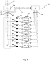
- the only figure 1 shows a block diagram of a charging system on which the method according to the invention can be carried out.
- the system 10 shown comprises a power grid connection 15 with a plurality of phases 14, for example a first phase 11, a second phase 12 and a third phase 13, to which electrical consumers, for example electric vehicles 16, hereinafter referred to as electric vehicle 16, are connected for charging the electric vehicles 16 can become.
- the electric vehicles 16 are each connected to a sub-distribution 17 via a charging point 19 .
- a control device 18 is provided, which monitors the system 10 .
- a phase current measuring device 20 is provided for each phase 11, 12, 13, 14, which transmits the values of the measured phase currents to the control device 18.
- Data connections 22 are preferably provided for the transmission of the values of the measured phase currents.
- data connections 22 is provided between the control device 18 and the electric vehicles 16, via which a performance specification can be transmitted from the control device 18 to the electric vehicles 16.
- phase current measuring device 20 data from a networked electricity meter can also be evaluated in order to draw conclusions about the phase currents.
- the control device 18 controls the electric vehicles 16 in such a way that the currents drawn from the electric vehicles 16 via the individual phases 11, 12, 13, 14 are such that the individual phases 11, 12, 13, 14 are loaded within predetermined operating parameters.
- These operating parameters include in particular a maximum power or a maximum phase current of the phases 11, 12, 13, 14.
- the operating parameters can also include a maximum unbalanced load between the phases 11, 12, 13, 14.
- the unbalanced load is defined by the greatest difference in the services that are called up over phases 11, 12, 13, 14.
- the unbalanced load is the load difference between the load of phase 11, 12, 13, 14, through which the greatest power is delivered, and the load of phase 11, 12, 13, 14, through which the lowest power is delivered.
- the load or the unbalanced load can be defined, for example, via the electrical power or the electrical current.
- the control device determines the maximum available charging power for the motor vehicle 16 and transmits this currently maximum available charging power to this motor vehicle 16. The motor vehicle 16 will then draw a maximum of this charging power via phase 11, 12, 13, 14. As the charging process continues, the control device 18 will continuously monitor the phase currents of the individual phases 11, 12, 13, 14 and, if necessary, output specifications transmit the motor vehicles 16, which signal the motor vehicles 16 that either more charging power may be retrieved, or that the charging power must be reduced.
- the maximum available charging power is given by the maximum unbalanced load.
- the maximum permitted unbalanced load is usually 20 amperes. It follows that the electric vehicle 16 can only charge with 20 amps.
- the phase currents are continuously monitored even when three electric vehicles 16 are connected, in order to be able to throttle the charging currents of individual electric vehicles 16, if necessary, in order to prevent the maximum permissible unbalanced load from being exceeded.
- the power specification is regularly used changed at a loading point 19.
- the phase currents at balance point 24 are observed. If the change in phase current matches the change in power specification, the electric vehicle 16 has charged with the full charge current according to the power specification.
- the change in the performance specification is repeated for each charging point 19 after a repetition time interval. As a result, the assessment of the regulatory potential remains up-to-date.
Landscapes
- Engineering & Computer Science (AREA)
- Power Engineering (AREA)
- Transportation (AREA)
- Mechanical Engineering (AREA)
- Supply And Distribution Of Alternating Current (AREA)
- Charge And Discharge Circuits For Batteries Or The Like (AREA)
Claims (13)
- Procédé de fonctionnement d'un système de charge (10) avec plusieurs points de charge (19) pour le chargement de consommateurs électriques (16), par exemple de véhicules électriques,- dans lequel le système de charge (10) est raccordé à un réseau électrique doté de plusieurs phases (11, 12, 13, 14),- dans lequel des courants de phase des phases (11, 12, 13, 14) du réseau électrique sont mesurés au niveau d'un point d'équilibre (24),- dans lequel des spécifications de puissance sont transmises à des consommateurs électriques (16) qui sont raccordés à un des points de charge (19),- dans lequel la spécification de puissance pour un intervalle de temps de test défini est modifiée individuellement régulièrement pour chaque point de charge (19) et la modification en résultant des courants de phase est mesurée au niveau du point d'équilibre (24), et
la modification en résultant des courants de phase permet de déterminer si un tel consommateur (16) est encore raccordé au point de charge (19), si le consommateur (16) se charge de manière significative et/ou si le consommateur (16) peut charger un courant supérieur,- dans lequel la modification de la spécification de puissance est répétée au niveau de chaque point de charge (19) en fonction d'un intervalle de temps de répétition défini,caractérisé en ce que,- chaque point de charge (19) est connecté précisément à une phase (11, 12, 13) des phases (11, 12, 13). - Procédé selon la revendication 1,
caractérisé en ce que,
la spécification de puissance pour l'intervalle de temps de test est augmentée ou réduite. - Procédé selon l'une quelconque des revendications 1 à 2,
caractérisé en ce que,- une charge déséquilibrée des phases (1112, 13, 14) est maintenue en dessous d'une valeur limite de charge déséquilibrée, dans la mesure où une spécification de puissance adaptée est transmise à chaque consommateur électrique (16) raccordé pour la charge. - Procédé selon l'une quelconque des revendications 1 à 3,
caractérisé en ce que,
la spécification de puissance comprend la quantité de puissance de charge supplémentaire qui peut être réellement prélevée ou la quantité de puissance de charge qui doit être réduite. - Procédé selon la revendication 4,
caractérisé en ce que,- lorsque le courant de phase d'une phase (11, 12, 13, 14) se situe en dessous d'une valeur limite de charge et que le courant de phase de cette phase (11, 12, 13, 14) est inférieur au plus petit courant de phase mesuré d'une des autres phases (11, 12, 13, 14) en sus de la valeur limite de charge déséquilibrée, la spécification de puissance permet de signaler qu'une puissance de charge supplémentaire peut être prélevée,- lorsque le courant de phase d'une phase (11, 12, 13, 14) se situe au-dessus d'une valeur limite de charge ou que le courant de phase de cette phase (11, 12, 13, 14) est supérieur au plus petit courant de phase mesuré d'une des autres phases (11, 12, 13, 14) en sus de la valeur limite de charge déséquilibrée, la spécification de puissance permet de signaler que la puissance de charge supplémentaire doit être réduite. - Procédé selon l'une quelconque des revendications 1 à 5,
caractérisé en ce que,
la spécification de puissance comprend une puissance de charge disponible maximale en cours. - Procédé selon la revendication 6,
caractérisé en ce que,
la puissance de charge disponible maximale en cours de la phase (11, 12, 13, 14), en tenant compte au moins des courants de phase en cours, d'une puissance maximale autorisée de la phase respective (11, 12, 13, 14) et d'une charge déséquilibrée maximale autorisée est déterminée entre les phases (11, 12, 13, 14). - Procédé selon la revendication 6 ou 7,
caractérisé en ce que,
lorsqu'un consommateur électrique (16) est raccordé pour la charge, la phase (11, 12, 13, 14) à laquelle le consommateur électrique (16) est raccordé est déterminée, et une puissance de charge disponible maximale en cours de la phase (11, 12, 13, 14) à laquelle est raccordé le consommateur électrique, est déterminée, et la puissance de charge disponible maximale en cours est transmise au consommateur électrique (16). - Procédé selon l'une quelconque des revendications 1 à 8,
caractérisé en ce que,
les spécifications de puissance sont sélectionnées de telle sorte qu'une charge individuelle des différentes phases (11, 12, 13, 14) est maintenue en sus en dessous d'une valeur limite de charge. - Procédé selon l'une quelconque des revendications 1 à 9,
caractérisé en ce que,
les courants de phase au point d'équilibre (24) sont déterminés en continu, et les spécifications de puissance pour les consommateurs électriques (16) raccordés pour la charge sont adaptées en continu et transmises au consommateur électrique respectif (16). - Procédé selon l'une quelconque des revendications 1 à 10,
caractérisé en ce que,
les consommateurs électriques (16) ajustent la puissance de charge appelée au moyen des spécifications de charge transmises. - Procédé selon l'une quelconque des revendications 1 à 11,
caractérisé en ce que,
les spécifications de puissance sont transmises par l'intermédiaire d'un signal PWM. - Procédé selon l'une quelconque des revendications 1 à 12,
caractérisé en ce que,
les consommateurs électriques (16) raccordés pour la charge sont des véhicules électriques.
Applications Claiming Priority (1)
| Application Number | Priority Date | Filing Date | Title |
|---|---|---|---|
| DE102018208396.7A DE102018208396A1 (de) | 2018-05-28 | 2018-05-28 | Verfahren zum Betreiben eines Ladesystems mit mehreren Ladepunkten |
Publications (2)
| Publication Number | Publication Date |
|---|---|
| EP3576246A1 EP3576246A1 (fr) | 2019-12-04 |
| EP3576246B1 true EP3576246B1 (fr) | 2023-01-04 |
Family
ID=66323757
Family Applications (1)
| Application Number | Title | Priority Date | Filing Date |
|---|---|---|---|
| EP19171592.9A Active EP3576246B1 (fr) | 2018-05-28 | 2019-04-29 | Procédé de fonctionnement d'un système de charge à une pluralité de points de charge |
Country Status (4)
| Country | Link |
|---|---|
| US (1) | US11631977B2 (fr) |
| EP (1) | EP3576246B1 (fr) |
| DE (1) | DE102018208396A1 (fr) |
| ES (1) | ES2936615T3 (fr) |
Families Citing this family (8)
| Publication number | Priority date | Publication date | Assignee | Title |
|---|---|---|---|---|
| DE202022105943U1 (de) | 2021-10-22 | 2022-10-31 | smopi® - Multi Chargepoint Solution GmbH | Ladestation |
| NO347232B1 (en) * | 2022-05-31 | 2023-07-17 | Defa As | An electric vehicle supply equipment, a method for customizing the charging pattern of batteries of an electric vehicle supply equipment and a system for customizing the charging pattern of batteries of an electric vehicle supply equipment |
| GB2628250B (en) * | 2022-06-13 | 2025-06-11 | 3Ti Energy Hubs Ltd | A controller |
| GB2619910B (en) * | 2022-06-13 | 2024-07-24 | 3Ti Energy Hubs Ltd | A controller |
| EP4336692A1 (fr) * | 2022-09-12 | 2024-03-13 | ABB E-Mobility B.V. | Dispositif de charge pour équilibrer des courants de phase |
| US11890960B1 (en) * | 2022-12-29 | 2024-02-06 | Rivian Ip Holdings, Llc | Interface based electrical load management |
| US20240308378A1 (en) * | 2023-03-14 | 2024-09-19 | Rivian Ip Holdings, Llc | Phase balanced load management at a charging site |
| FR3166108A1 (fr) * | 2024-09-09 | 2026-03-13 | Ampere Sas | Système de chargement électrique d’un véhicule |
Citations (1)
| Publication number | Priority date | Publication date | Assignee | Title |
|---|---|---|---|---|
| US20130049677A1 (en) * | 2010-03-05 | 2013-02-28 | Abb B,V, | System, devices and method for charging a battery of an electric vehicle |
Family Cites Families (21)
| Publication number | Priority date | Publication date | Assignee | Title |
|---|---|---|---|---|
| CN1261319C (zh) * | 2004-11-11 | 2006-06-28 | 北京电巴科技有限公司 | 一种电动公交系统 |
| US7612466B2 (en) * | 2008-01-28 | 2009-11-03 | VPT Energy Systems | System and method for coordinated control and utilization of local storage and generation, with a power grid |
| US8315745B2 (en) * | 2009-04-24 | 2012-11-20 | Hunter Defense Technologies, Inc. | Mobile micro-grid power system controller and method |
| ES2777887T3 (es) * | 2010-05-03 | 2020-08-06 | Siemens Gamesa Renewable Energy As | Sistema para intercambiar energía eléctrica entre una batería y una red eléctrica y procedimiento respectivo |
| US8594859B2 (en) * | 2010-10-18 | 2013-11-26 | Qualcomm Incorporated | Method and system for real-time aggregation of electric vehicle information for real-time auctioning of ancillary services, and real-time lowest cost matching electric vehicle energy demand to charging services |
| FR2971897B1 (fr) * | 2011-02-18 | 2013-02-22 | Commissariat Energie Atomique | Dispositif d'equilibrage de charge sur un reseau polyphase |
| US20120265459A1 (en) * | 2011-04-14 | 2012-10-18 | General Electric Company | Integrated electric meter and electric vehicle charging station (evcs) |
| US9281689B2 (en) * | 2011-06-08 | 2016-03-08 | General Electric Technology Gmbh | Load phase balancing at multiple tiers of a multi-tier hierarchical intelligent power distribution grid |
| JP6408382B2 (ja) * | 2012-02-13 | 2018-10-17 | アクセンチュア グローバル サービスィズ リミテッド | 電気自動車の分散型インテリジェンス |
| WO2013159073A1 (fr) | 2012-04-20 | 2013-10-24 | Pedia Solutions, Llc | Appareil et procédés d'administration orale de fluides et d'utilisation d'instrumentation médicale |
| FR2993514B1 (fr) * | 2012-07-20 | 2015-12-04 | Schneider Electric Ind Sas | Procede et dispositif de distribution d'energie electrique |
| JP2015525057A (ja) * | 2012-08-16 | 2015-08-27 | ロベルト・ボッシュ・ゲゼルシャフト・ミト・ベシュレンクテル・ハフツングRobert Bosch Gmbh | エネルギー貯蔵器および制御システムを備えるdcビルディングシステム |
| US9562935B2 (en) * | 2012-10-19 | 2017-02-07 | Lear Corporation | Apparatus and method for detecting a phase sequence in a vehicle |
| DE102012221473A1 (de) * | 2012-11-23 | 2014-05-28 | Thomas Bichler | Verfahren zum Laden einer Fahrbatterie |
| EP2806520A1 (fr) * | 2013-05-22 | 2014-11-26 | Vito NV | Système et procédé de commande de réseau d'alimentation électrique |
| CN203772983U (zh) * | 2014-03-07 | 2014-08-13 | 国家电网公司 | 一种低压配电不平衡补偿装置测试平台 |
| DE102014003250A1 (de) * | 2014-03-12 | 2015-09-17 | Rwe Deutschland Ag | Verfahren zum Betreiben eines elektrischen Teilnehmers, einer elektrischen Messstelle an einem Teilnehmernetz sowie einen elektrischen Teilnehmer als auch eine elektrische Messstelle |
| US9616763B2 (en) * | 2014-06-12 | 2017-04-11 | King Fahd University Of Petroleum And Minerals | Autonomous charging management system for electric vehicles |
| US9461707B1 (en) * | 2015-05-21 | 2016-10-04 | Landis+Gyr Technologies, Llc | Power-line network with multi-scheme communication |
| US20170271984A1 (en) * | 2016-03-04 | 2017-09-21 | Atigeo Corp. | Using battery dc characteristics to control power output |
| US20180123391A1 (en) * | 2016-10-28 | 2018-05-03 | Totem Power, Inc. | System and Method for Dynamic Measurement and Control of Synchronized Remote Energy Resources |
-
2018
- 2018-05-28 DE DE102018208396.7A patent/DE102018208396A1/de active Pending
-
2019
- 2019-04-29 ES ES19171592T patent/ES2936615T3/es active Active
- 2019-04-29 EP EP19171592.9A patent/EP3576246B1/fr active Active
- 2019-05-24 US US16/422,402 patent/US11631977B2/en active Active
Patent Citations (1)
| Publication number | Priority date | Publication date | Assignee | Title |
|---|---|---|---|---|
| US20130049677A1 (en) * | 2010-03-05 | 2013-02-28 | Abb B,V, | System, devices and method for charging a battery of an electric vehicle |
Also Published As
| Publication number | Publication date |
|---|---|
| EP3576246A1 (fr) | 2019-12-04 |
| US11631977B2 (en) | 2023-04-18 |
| ES2936615T3 (es) | 2023-03-21 |
| DE102018208396A1 (de) | 2019-11-28 |
| US20190359077A1 (en) | 2019-11-28 |
Similar Documents
| Publication | Publication Date | Title |
|---|---|---|
| EP3544145B1 (fr) | Procédé de charge des consommateurs électriques | |
| EP3576246A1 (fr) | Procédé de fonctionnement d'un système de charge à une pluralité de points de charge | |
| DE102018106308B4 (de) | Modulationsindexverbesserung durch intelligente Batterie | |
| EP3934931A1 (fr) | Station de charge pour charger des véhicules électriques | |
| EP2569840A2 (fr) | Dispositif de commutation | |
| EP3417523B1 (fr) | Procédé de commande d'un transformateur de régulation et installation électrique de couplage de deux réseaux à courant alternatif | |
| DE112010006053T5 (de) | Ladevorrichtung und Verfahren zum Steuern einer Ladevorrichtung | |
| DE112019005307T5 (de) | Spannungsversorgungssystem und dieses bildende Leistungsquelle | |
| EP2735468A2 (fr) | Procédé de charge d'une batterie de traction | |
| EP3566276A1 (fr) | Procédé pour faire fonctionner un abonné d'un réseau d'alimentation | |
| DE102018202259B4 (de) | Ladestation zum Laden von Elektrofahrzeugen mit verteilter Energiemessung sowie Verfahren | |
| WO2011157488A2 (fr) | Procédé d'équilibrage de tension réseau | |
| EP3371847A1 (fr) | Procédé pour faire fonctionner une batterie et batterie | |
| DE102015105152A1 (de) | Anordnung und Verfahren zum Verringern einer Schieflast in einem dreiphasigen Verteilungsnetz | |
| EP2869072A1 (fr) | Dispositif et procédé de détection de l'énergie électrique de consommateurs mono ou multiphasés | |
| DE112022002486T5 (de) | Einstellung der umrichterklemmenspannung in leistungssystem | |
| DE102021004783A1 (de) | Verfahren zur Regelung einer Einspeiseleistung | |
| WO2019166342A1 (fr) | Dispositif de connexion d'un réseau partiel à un réseau à tension alternative et procédé de commande d'une sortie électrique | |
| EP4391272A1 (fr) | Procédé de gestion d'énergie lors de la fourniture d'énergie électrique, produit programme informatique, système et véhicule | |
| DE102013113437A1 (de) | Verfahren zum Kalibrieren eines elektrisch angetriebenen Fahrzeugs auf einen Netzstandard | |
| EP3624290A1 (fr) | Procédé et dispositif de commande destiné au fonctionnement d'un réseau de distribution d'énergie électrique | |
| EP3123607B1 (fr) | Système mutateur modulaire pour réseau de distribution électrique | |
| DE10138399A1 (de) | Verfahren zum Betreiben einer Windenergieanlage | |
| DE212019000262U1 (de) | System zum Leistungsausgleich | |
| EP3131168A1 (fr) | Procede et systeme pour la determination de points de mesure dans un reseau d'energie |
Legal Events
| Date | Code | Title | Description |
|---|---|---|---|
| PUAI | Public reference made under article 153(3) epc to a published international application that has entered the european phase |
Free format text: ORIGINAL CODE: 0009012 |
|
| STAA | Information on the status of an ep patent application or granted ep patent |
Free format text: STATUS: THE APPLICATION HAS BEEN PUBLISHED |
|
| AK | Designated contracting states |
Kind code of ref document: A1 Designated state(s): AL AT BE BG CH CY CZ DE DK EE ES FI FR GB GR HR HU IE IS IT LI LT LU LV MC MK MT NL NO PL PT RO RS SE SI SK SM TR |
|
| AX | Request for extension of the european patent |
Extension state: BA ME |
|
| STAA | Information on the status of an ep patent application or granted ep patent |
Free format text: STATUS: REQUEST FOR EXAMINATION WAS MADE |
|
| 17P | Request for examination filed |
Effective date: 20200311 |
|
| RBV | Designated contracting states (corrected) |
Designated state(s): AL AT BE BG CH CY CZ DE DK EE ES FI FR GB GR HR HU IE IS IT LI LT LU LV MC MK MT NL NO PL PT RO RS SE SI SK SM TR |
|
| STAA | Information on the status of an ep patent application or granted ep patent |
Free format text: STATUS: EXAMINATION IS IN PROGRESS |
|
| 17Q | First examination report despatched |
Effective date: 20200708 |
|
| GRAP | Despatch of communication of intention to grant a patent |
Free format text: ORIGINAL CODE: EPIDOSNIGR1 |
|
| STAA | Information on the status of an ep patent application or granted ep patent |
Free format text: STATUS: GRANT OF PATENT IS INTENDED |
|
| INTG | Intention to grant announced |
Effective date: 20221014 |
|
| GRAS | Grant fee paid |
Free format text: ORIGINAL CODE: EPIDOSNIGR3 |
|
| GRAA | (expected) grant |
Free format text: ORIGINAL CODE: 0009210 |
|
| STAA | Information on the status of an ep patent application or granted ep patent |
Free format text: STATUS: THE PATENT HAS BEEN GRANTED |
|
| AK | Designated contracting states |
Kind code of ref document: B1 Designated state(s): AL AT BE BG CH CY CZ DE DK EE ES FI FR GB GR HR HU IE IS IT LI LT LU LV MC MK MT NL NO PL PT RO RS SE SI SK SM TR |
|
| REG | Reference to a national code |
Ref country code: GB Ref legal event code: FG4D Free format text: NOT ENGLISH |
|
| REG | Reference to a national code |
Ref country code: DE Ref legal event code: R096 Ref document number: 502019006674 Country of ref document: DE |
|
| REG | Reference to a national code |
Ref country code: CH Ref legal event code: EP |
|
| REG | Reference to a national code |
Ref country code: AT Ref legal event code: REF Ref document number: 1542627 Country of ref document: AT Kind code of ref document: T Effective date: 20230115 |
|
| REG | Reference to a national code |
Ref country code: IE Ref legal event code: FG4D Free format text: LANGUAGE OF EP DOCUMENT: GERMAN |
|
| REG | Reference to a national code |
Ref country code: ES Ref legal event code: FG2A Ref document number: 2936615 Country of ref document: ES Kind code of ref document: T3 Effective date: 20230321 |
|
| REG | Reference to a national code |
Ref country code: LT Ref legal event code: MG9D |
|
| REG | Reference to a national code |
Ref country code: NL Ref legal event code: MP Effective date: 20230104 |
|
| PG25 | Lapsed in a contracting state [announced via postgrant information from national office to epo] |
Ref country code: NL Free format text: LAPSE BECAUSE OF FAILURE TO SUBMIT A TRANSLATION OF THE DESCRIPTION OR TO PAY THE FEE WITHIN THE PRESCRIBED TIME-LIMIT Effective date: 20230104 |
|
| PG25 | Lapsed in a contracting state [announced via postgrant information from national office to epo] |
Ref country code: RS Free format text: LAPSE BECAUSE OF FAILURE TO SUBMIT A TRANSLATION OF THE DESCRIPTION OR TO PAY THE FEE WITHIN THE PRESCRIBED TIME-LIMIT Effective date: 20230104 Ref country code: PT Free format text: LAPSE BECAUSE OF FAILURE TO SUBMIT A TRANSLATION OF THE DESCRIPTION OR TO PAY THE FEE WITHIN THE PRESCRIBED TIME-LIMIT Effective date: 20230504 Ref country code: NO Free format text: LAPSE BECAUSE OF FAILURE TO SUBMIT A TRANSLATION OF THE DESCRIPTION OR TO PAY THE FEE WITHIN THE PRESCRIBED TIME-LIMIT Effective date: 20230404 Ref country code: LV Free format text: LAPSE BECAUSE OF FAILURE TO SUBMIT A TRANSLATION OF THE DESCRIPTION OR TO PAY THE FEE WITHIN THE PRESCRIBED TIME-LIMIT Effective date: 20230104 Ref country code: LT Free format text: LAPSE BECAUSE OF FAILURE TO SUBMIT A TRANSLATION OF THE DESCRIPTION OR TO PAY THE FEE WITHIN THE PRESCRIBED TIME-LIMIT Effective date: 20230104 Ref country code: HR Free format text: LAPSE BECAUSE OF FAILURE TO SUBMIT A TRANSLATION OF THE DESCRIPTION OR TO PAY THE FEE WITHIN THE PRESCRIBED TIME-LIMIT Effective date: 20230104 |
|
| PG25 | Lapsed in a contracting state [announced via postgrant information from national office to epo] |
Ref country code: SE Free format text: LAPSE BECAUSE OF FAILURE TO SUBMIT A TRANSLATION OF THE DESCRIPTION OR TO PAY THE FEE WITHIN THE PRESCRIBED TIME-LIMIT Effective date: 20230104 Ref country code: PL Free format text: LAPSE BECAUSE OF FAILURE TO SUBMIT A TRANSLATION OF THE DESCRIPTION OR TO PAY THE FEE WITHIN THE PRESCRIBED TIME-LIMIT Effective date: 20230104 Ref country code: IS Free format text: LAPSE BECAUSE OF FAILURE TO SUBMIT A TRANSLATION OF THE DESCRIPTION OR TO PAY THE FEE WITHIN THE PRESCRIBED TIME-LIMIT Effective date: 20230504 Ref country code: GR Free format text: LAPSE BECAUSE OF FAILURE TO SUBMIT A TRANSLATION OF THE DESCRIPTION OR TO PAY THE FEE WITHIN THE PRESCRIBED TIME-LIMIT Effective date: 20230405 Ref country code: FI Free format text: LAPSE BECAUSE OF FAILURE TO SUBMIT A TRANSLATION OF THE DESCRIPTION OR TO PAY THE FEE WITHIN THE PRESCRIBED TIME-LIMIT Effective date: 20230104 |
|
| REG | Reference to a national code |
Ref country code: DE Ref legal event code: R097 Ref document number: 502019006674 Country of ref document: DE |
|
| PG25 | Lapsed in a contracting state [announced via postgrant information from national office to epo] |
Ref country code: SM Free format text: LAPSE BECAUSE OF FAILURE TO SUBMIT A TRANSLATION OF THE DESCRIPTION OR TO PAY THE FEE WITHIN THE PRESCRIBED TIME-LIMIT Effective date: 20230104 Ref country code: RO Free format text: LAPSE BECAUSE OF FAILURE TO SUBMIT A TRANSLATION OF THE DESCRIPTION OR TO PAY THE FEE WITHIN THE PRESCRIBED TIME-LIMIT Effective date: 20230104 Ref country code: EE Free format text: LAPSE BECAUSE OF FAILURE TO SUBMIT A TRANSLATION OF THE DESCRIPTION OR TO PAY THE FEE WITHIN THE PRESCRIBED TIME-LIMIT Effective date: 20230104 Ref country code: DK Free format text: LAPSE BECAUSE OF FAILURE TO SUBMIT A TRANSLATION OF THE DESCRIPTION OR TO PAY THE FEE WITHIN THE PRESCRIBED TIME-LIMIT Effective date: 20230104 Ref country code: CZ Free format text: LAPSE BECAUSE OF FAILURE TO SUBMIT A TRANSLATION OF THE DESCRIPTION OR TO PAY THE FEE WITHIN THE PRESCRIBED TIME-LIMIT Effective date: 20230104 |
|
| PLBE | No opposition filed within time limit |
Free format text: ORIGINAL CODE: 0009261 |
|
| STAA | Information on the status of an ep patent application or granted ep patent |
Free format text: STATUS: NO OPPOSITION FILED WITHIN TIME LIMIT |
|
| PG25 | Lapsed in a contracting state [announced via postgrant information from national office to epo] |
Ref country code: SK Free format text: LAPSE BECAUSE OF FAILURE TO SUBMIT A TRANSLATION OF THE DESCRIPTION OR TO PAY THE FEE WITHIN THE PRESCRIBED TIME-LIMIT Effective date: 20230104 |
|
| REG | Reference to a national code |
Ref country code: CH Ref legal event code: PL |
|
| 26N | No opposition filed |
Effective date: 20231005 |
|
| PG25 | Lapsed in a contracting state [announced via postgrant information from national office to epo] |
Ref country code: LU Free format text: LAPSE BECAUSE OF NON-PAYMENT OF DUE FEES Effective date: 20230429 |
|
| REG | Reference to a national code |
Ref country code: BE Ref legal event code: MM Effective date: 20230430 |
|
| PG25 | Lapsed in a contracting state [announced via postgrant information from national office to epo] |
Ref country code: MC Free format text: LAPSE BECAUSE OF FAILURE TO SUBMIT A TRANSLATION OF THE DESCRIPTION OR TO PAY THE FEE WITHIN THE PRESCRIBED TIME-LIMIT Effective date: 20230104 |
|
| PG25 | Lapsed in a contracting state [announced via postgrant information from national office to epo] |
Ref country code: SI Free format text: LAPSE BECAUSE OF FAILURE TO SUBMIT A TRANSLATION OF THE DESCRIPTION OR TO PAY THE FEE WITHIN THE PRESCRIBED TIME-LIMIT Effective date: 20230104 Ref country code: MC Free format text: LAPSE BECAUSE OF FAILURE TO SUBMIT A TRANSLATION OF THE DESCRIPTION OR TO PAY THE FEE WITHIN THE PRESCRIBED TIME-LIMIT Effective date: 20230104 Ref country code: LI Free format text: LAPSE BECAUSE OF NON-PAYMENT OF DUE FEES Effective date: 20230430 Ref country code: CH Free format text: LAPSE BECAUSE OF NON-PAYMENT OF DUE FEES Effective date: 20230430 |
|
| REG | Reference to a national code |
Ref country code: IE Ref legal event code: MM4A |
|
| PG25 | Lapsed in a contracting state [announced via postgrant information from national office to epo] |
Ref country code: BE Free format text: LAPSE BECAUSE OF NON-PAYMENT OF DUE FEES Effective date: 20230430 |
|
| PG25 | Lapsed in a contracting state [announced via postgrant information from national office to epo] |
Ref country code: IE Free format text: LAPSE BECAUSE OF NON-PAYMENT OF DUE FEES Effective date: 20230429 |
|
| PG25 | Lapsed in a contracting state [announced via postgrant information from national office to epo] |
Ref country code: IE Free format text: LAPSE BECAUSE OF NON-PAYMENT OF DUE FEES Effective date: 20230429 |
|
| P01 | Opt-out of the competence of the unified patent court (upc) registered |
Effective date: 20240527 |
|
| PG25 | Lapsed in a contracting state [announced via postgrant information from national office to epo] |
Ref country code: BG Free format text: LAPSE BECAUSE OF FAILURE TO SUBMIT A TRANSLATION OF THE DESCRIPTION OR TO PAY THE FEE WITHIN THE PRESCRIBED TIME-LIMIT Effective date: 20230104 |
|
| PG25 | Lapsed in a contracting state [announced via postgrant information from national office to epo] |
Ref country code: BG Free format text: LAPSE BECAUSE OF FAILURE TO SUBMIT A TRANSLATION OF THE DESCRIPTION OR TO PAY THE FEE WITHIN THE PRESCRIBED TIME-LIMIT Effective date: 20230104 |
|
| PG25 | Lapsed in a contracting state [announced via postgrant information from national office to epo] |
Ref country code: CY Free format text: LAPSE BECAUSE OF FAILURE TO SUBMIT A TRANSLATION OF THE DESCRIPTION OR TO PAY THE FEE WITHIN THE PRESCRIBED TIME-LIMIT; INVALID AB INITIO Effective date: 20190429 |
|
| PG25 | Lapsed in a contracting state [announced via postgrant information from national office to epo] |
Ref country code: HU Free format text: LAPSE BECAUSE OF FAILURE TO SUBMIT A TRANSLATION OF THE DESCRIPTION OR TO PAY THE FEE WITHIN THE PRESCRIBED TIME-LIMIT; INVALID AB INITIO Effective date: 20190429 |
|
| PG25 | Lapsed in a contracting state [announced via postgrant information from national office to epo] |
Ref country code: TR Free format text: LAPSE BECAUSE OF FAILURE TO SUBMIT A TRANSLATION OF THE DESCRIPTION OR TO PAY THE FEE WITHIN THE PRESCRIBED TIME-LIMIT Effective date: 20230104 |
|
| PGFP | Annual fee paid to national office [announced via postgrant information from national office to epo] |
Ref country code: ES Payment date: 20260615 Year of fee payment: 8 |
|
| PGFP | Annual fee paid to national office [announced via postgrant information from national office to epo] |
Ref country code: GB Payment date: 20260423 Year of fee payment: 8 |
|
| PGFP | Annual fee paid to national office [announced via postgrant information from national office to epo] |
Ref country code: IT Payment date: 20260427 Year of fee payment: 8 |
|
| PGFP | Annual fee paid to national office [announced via postgrant information from national office to epo] |
Ref country code: DE Payment date: 20260422 Year of fee payment: 8 |
|
| PGFP | Annual fee paid to national office [announced via postgrant information from national office to epo] |
Ref country code: AT Payment date: 20260421 Year of fee payment: 8 |
|
| PGFP | Annual fee paid to national office [announced via postgrant information from national office to epo] |
Ref country code: FR Payment date: 20260420 Year of fee payment: 8 |