EP3576261B1 - Moteur et compresseur qui l'utilise - Google Patents
Moteur et compresseur qui l'utilise Download PDFInfo
- Publication number
- EP3576261B1 EP3576261B1 EP17894314.8A EP17894314A EP3576261B1 EP 3576261 B1 EP3576261 B1 EP 3576261B1 EP 17894314 A EP17894314 A EP 17894314A EP 3576261 B1 EP3576261 B1 EP 3576261B1
- Authority
- EP
- European Patent Office
- Prior art keywords
- motor
- motor casing
- stator
- rotor
- iron core
- Prior art date
- Legal status (The legal status is an assumption and is not a legal conclusion. Google has not performed a legal analysis and makes no representation as to the accuracy of the status listed.)
- Active
Links
Images




Classifications
-
- H—ELECTRICITY
- H02—GENERATION; CONVERSION OR DISTRIBUTION OF ELECTRIC POWER
- H02K—DYNAMO-ELECTRIC MACHINES
- H02K3/00—Details of windings
- H02K3/32—Windings characterised by the shape, form or construction of the insulation
- H02K3/34—Windings characterised by the shape, form or construction of the insulation between conductors or between conductor and core, e.g. slot insulation
- H02K3/345—Windings characterised by the shape, form or construction of the insulation between conductors or between conductor and core, e.g. slot insulation between conductor and core, e.g. slot insulation
-
- H—ELECTRICITY
- H02—GENERATION; CONVERSION OR DISTRIBUTION OF ELECTRIC POWER
- H02K—DYNAMO-ELECTRIC MACHINES
- H02K5/00—Casings; Enclosures; Supports
- H02K5/04—Casings or enclosures characterised by the shape, form or construction thereof
- H02K5/18—Casings or enclosures characterised by the shape, form or construction thereof with ribs or fins for improving heat transfer
-
- F—MECHANICAL ENGINEERING; LIGHTING; HEATING; WEAPONS; BLASTING
- F25—REFRIGERATION OR COOLING; COMBINED HEATING AND REFRIGERATION SYSTEMS; HEAT PUMP SYSTEMS; MANUFACTURE OR STORAGE OF ICE; LIQUEFACTION SOLIDIFICATION OF GASES
- F25B—REFRIGERATION MACHINES, PLANTS OR SYSTEMS; COMBINED HEATING AND REFRIGERATION SYSTEMS; HEAT PUMP SYSTEMS
- F25B31/00—Compressor arrangements
- F25B31/02—Compressor arrangements of motor-compressor units
- F25B31/026—Compressor arrangements of motor-compressor units with compressor of rotary type
-
- H—ELECTRICITY
- H02—GENERATION; CONVERSION OR DISTRIBUTION OF ELECTRIC POWER
- H02K—DYNAMO-ELECTRIC MACHINES
- H02K1/00—Details of the magnetic circuit
- H02K1/02—Details of the magnetic circuit characterised by the magnetic material
-
- H—ELECTRICITY
- H02—GENERATION; CONVERSION OR DISTRIBUTION OF ELECTRIC POWER
- H02K—DYNAMO-ELECTRIC MACHINES
- H02K1/00—Details of the magnetic circuit
- H02K1/06—Details of the magnetic circuit characterised by the shape, form or construction
- H02K1/22—Rotating parts of the magnetic circuit
- H02K1/27—Rotor cores with permanent magnets
- H02K1/2793—Rotors axially facing stators
- H02K1/2795—Rotors axially facing stators the rotor consisting of two or more circumferentially positioned magnets
-
- H—ELECTRICITY
- H02—GENERATION; CONVERSION OR DISTRIBUTION OF ELECTRIC POWER
- H02K—DYNAMO-ELECTRIC MACHINES
- H02K5/00—Casings; Enclosures; Supports
- H02K5/04—Casings or enclosures characterised by the shape, form or construction thereof
- H02K5/20—Casings or enclosures characterised by the shape, form or construction thereof with channels or ducts for flow of cooling medium
- H02K5/207—Casings or enclosures characterised by the shape, form or construction thereof with channels or ducts for flow of cooling medium with openings in the casing specially adapted for ambient air
-
- H—ELECTRICITY
- H02—GENERATION; CONVERSION OR DISTRIBUTION OF ELECTRIC POWER
- H02K—DYNAMO-ELECTRIC MACHINES
- H02K7/00—Arrangements for handling mechanical energy structurally associated with dynamo-electric machines, e.g. structural association with mechanical driving motors or auxiliary dynamo-electric machines
- H02K7/14—Structural association with mechanical loads, e.g. with hand-held machine tools or fans
-
- H—ELECTRICITY
- H02—GENERATION; CONVERSION OR DISTRIBUTION OF ELECTRIC POWER
- H02K—DYNAMO-ELECTRIC MACHINES
- H02K9/00—Arrangements for cooling or ventilating
- H02K9/02—Arrangements for cooling or ventilating by ambient air flowing through the machine
- H02K9/04—Arrangements for cooling or ventilating by ambient air flowing through the machine having means for generating a flow of cooling medium
- H02K9/06—Arrangements for cooling or ventilating by ambient air flowing through the machine having means for generating a flow of cooling medium with fans or impellers driven by the machine shaft
-
- H—ELECTRICITY
- H02—GENERATION; CONVERSION OR DISTRIBUTION OF ELECTRIC POWER
- H02K—DYNAMO-ELECTRIC MACHINES
- H02K16/00—Machines with more than one rotor or stator
- H02K16/02—Machines with one stator and two or more rotors
Definitions
- the present invention relates to a motor and a compressor that uses the motor.
- a motor that drives a compressor has a configuration in which a rotor and a stator that drives the rotor are integrally accommodated in a motor casing.
- JP 2015 68248 A discloses a compressor in which a rotor and a stator are accommodated in a motor casing and which includes a drive shaft that penetrates the rotor so as to drive a turning scroll.
- US 2012/301 334 A1 discloses a compressor having an axial gap motor including a rotor and a stator as well as a coolant compression mechanism section disposed in a closed chamber and connected to the rotor of the axial gap motor via a crankshaft, wherein the stator of the axial gap motor is disposed outside of the closed chamber, and the coolant compression mechanism section of the compressor is driven by magnetic induction therebetween.
- JP 2003 021065 A discloses a compressor including a cylindrical casing, wherein an electric motor and compression means are provided in the casing and configured to compress and discharge fluid.
- the electric motor has a stator provided in the casing, the outer periphery of which includes a core having an arcuate surface and a flat surface formed by cutting out a part of the arcuate surface; and an outer periphery of a drive shaft positioned on an inner peripheral side of the stator, wherein the casing is provided with a screw hole at a position corresponding to a flat surface of the core in a radial direction of the casing, and a distal end side of the screw hole abuts on the flat surface of the core.
- JP 2015 050798 A discloses an axial gap type permanent magnet synchronous motor for reducing the shaft voltage.
- a high temperature or high pressure may be applied to the motor casing during an operation or manufacture.
- a high temperature or high pressure may be applied to the motor casing at the time of a resin press-fitting, and thus the motor casing may be distorted.
- an object of the invention is to provide a motor according to independent claim 1 for which high strength can be obtained in a motor casing and a compressor according to dependent claim 9 that uses the motor according to independent claim 1.
- the further dependent claims are directed to advantageous embodiments.
- the motor according to the invention has the features of independent claim 1 is provided, wherein the motor includes: a rotating shaft provided in a rotatable manner; a rotor that rotates integrally with the rotating shaft; a stator that rotationally drives the rotor; and a motor casing that is a cylindrical body for accommodating the rotor and the stator, and has, on an outer circumferential surface of the motor casing, ribs extending in a circumferential direction.
- the invention is configured also as a compressor having the features of co-independent claim 9 is provided that uses the above-described motor. Preferred embodiments are described in the dependent claims.
- FIGs. 1A and 1B illustrate external perspective views of a motor according to Example 1.
- 11 represents a motor cover
- 12 represents a rotating shaft
- 13 represents a cooling fan.
- the motor cover 11 has a motor casing 14 that houses a stator and a rotor.
- the motor cover 11 has a configuration in which the motor casing 14 has a cylindrical shape with opening portions formed on both sides, a flange 15 is provided at one opening portion, and an end bracket 16 is provided at another opening portion.
- the cooling fan 13 suctions external air from a suction hole provided at a side of an opposite surface of the end bracket 16 and generates cooling air through rotation of a rotary vane.
- the motor 10 may be an axial gap type in which the rotor and the stator are disposed to be opposite to each other in a direction parallel to the rotating shaft 12, or may be a radial gap type in which the stator is disposed at an outer diameter side of the rotor.
- An internal configuration of the motor casing 14 will be described below in detail.
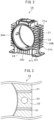
- Fig. 2 is a perspective view illustrating a configuration of the motor casing 14 detached from the motor cover 11.
- a plurality of cooling fins 21 that dissipate heat in the motor casing 14 are provided to project from outer circumferential surfaces of sides 20A and 20B and an underside 20C of the motor casing 14.
- the plurality of cooling fins 21 are each arrayed to extend side by side from one opening side to the other opening side of the motor casing 14. That is, the cooling fins 21 are provided to be aligned along the outer circumferential surfaces of the motor casing 14 in a state in which the fins are parallel to each other.
- an inner circumferential surface of the motor casing 14 has a fixing portion 24 formed for fixing the stator.
- Ribs 22 that extend in a circumferential direction of the motor casing 14 are provided to project from outer circumferential surfaces of the motor casing 14 at both sides 20A and 20B and the underside 20C of the motor casing 14.
- the ribs 22 intersect the cooling fins 21 so as to be formed integrally with the cooling fins at a substantially central position of the cooling fins 14 in a width direction.
- one line rib 22 is provided to intersect the cooling fins from the uppermost cooling fin 21a to the lowermost cooling fin 21b at each of the both sides 20A and 20B of the motor casing 14.
- the rib 22 is provided to intersect the cooling fins 21 from a left end side to a right end side in Fig. 2 at the substantially central position of the cooling fins 21 in the width direction.
- top portions 221 of the ribs 22 are all formed to be flush with top portions 211 of the cooling fins 21.
- the ribs 22 are provided on the outer circumferential surfaces of the motor casing 14, and thereby strength of the motor casing 14 increases in the circumferential direction thereof.
- Fig. 2 illustrates a configuration in which the rib 22 is provided to intersect the cooling fins from the uppermost cooling fin 21a to the lowermost cooling fin 21b at each of the both sides 20A and 20B of the motor casing 14.
- the motor 10 according to Example 1 is not limited thereto.
- the rib 22 may be provided from a position lower than the uppermost cooling fin 21a or may be provided from a position higher than the lowermost cooling fin 21b.
- one line rib 22 is provided at each center of the both sides 20A and 20B and the underside 20C of the motor casing 14.
- the configuration is not limited thereto, and multiple line of ribs may be provided at each of the both sides 20A and 20B and the underside 20C of the motor casing 14. Consequently, the strength of the motor casing 14 further increases.
- a configuration in which the ribs 22 are provided at the both sides 20A and 20B and the underside 20C of the motor casing 14 is illustrated.
- the motor 10 according to Example 1 is not limited thereto.
- the motor may have a configuration in which the rib 22 is provided at only one of the sides 20A and 20B of the motor casing 14 or a configuration in which the rib 22 is not provided at the underside 20C.
- the rib 22 is configured to be provided at the substantially central position of the cooling fins 21 in the width direction.
- the configuration is not limited thereto, and the rib 22 may be provided at a position close to the one opening side of the motor casing 14.
- Figs. 3 and 4 are enlarged views illustrating a part of the outer circumferential surface of the motor casing 14 of the motor according to Example 2.
- a vent hole 23 is provided at a part of the rib 22.
- a part of the rib 22 forms a recessed portion 222. That is, the recessed portion 222 at a part of the rib 22 is provided at a position lower than the top portion 211 of the cooling fin 21.
- the motor according to Example 2 has the same configuration as that of the motor 10 of Example 1 except for the description provided above, and thus the description thereof is omitted.
- Example 3 a manufacturing method suitable for preparing the motor casing 14 (refer to Fig. 2 ) of the motor 10 according to Example 1 is described.
- a sand mold is prepared. Preparation of the sand mold is as follows. Dies are prepared to produce shapes of outer circumferential surfaces corresponding to regions halved at the position of the rib 22 of the motor casing 14 illustrated in Fig. 2 , and the dies are each pressed against sand such that a left sand mold and a right sand mold as main molds are prepared. Further, a core for preparing a shape of the inner circumferential surface of the motor casing 14 is prepared by using the same sand as that used to prepare the main molds.
- molten metal is poured in the sand molds connected in (Process 2), remains as is for a predetermined time, and is cooled.
- molten Al can be used as the molten metal.
- a burr of the metal-molded body is polished and removed.
- the burr is generated when a part of the molten metal injected into the sand mold is solidified in a state of flowing out from a connection surface or the like of the sand mold.
- the position of the rib 22 is the connection surface between the left sand mold and the right sand mold, and thus the burr is mainly formed at the position of the rib 22.
- a front surface of the rib 22 or top portions of the cooling fins 21 around the rib is mainly polished by a grinder or the like, and thereby it is possible to remove most of the burr.
- the front surface of the rib 22 and a front surface of the cooling fin 21 are polished by a grinder or the like, and thereby the top portion 221 of the rib 22 is formed to be flush with the top portions 211 of the cooling fins 21.
- FIGs. 5A and 5B are perspective views of a state in which a compression unit 40 and the motor 10 of a compressor 100 according to Example 4 are separated from each other.
- the compressor 100 includes the compression unit 40 that compresses a fluid and the motor 10 that drives the compression unit 40.
- the motor 10 the motor 10 (refer to Figs. 1A, 1B , and 2 ) described in Example 1 is used.
- the motor 10 a configuration, in which an axial gap type motor is employed, will be described as an example.
- the flange 15 of the motor cover 11 is fastened with a main-body casing 41 of the compression unit 40, and thereby the motor 10 can be provided integrally with the compression unit 40.
- the rotating shaft 12 is inserted at a predetermined position of the compression unit 40, and a fastening bolt 42 is inserted into a bolt inserting hole 151 provided in the flange 15 of the motor cover 11 and a bolt inserting hole 411 provided in the main-body casing 41, and thereby the flange 15 of the motor 10 and the main-body casing 41 can be fastened with each other.
- An insertion position of the rotating shaft 12 in the compression unit 40 will be described below.
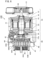
- Fig. 6 illustrates a cross-sectional view of the compressor 100 having a configuration in which the motor 10 and the compression unit 40 illustrated in Figs. 5A and 5B are integrated with each other, when viewed from a side.
- a disk-shaped stator 31 is disposed between a pair of disk-shaped rotors 32.
- the rotating shaft 12 is provided to penetrate a central portion of the stator 31 and the rotors 32 and is rotatably supported by a main bearing 33 provided on a side of the compression unit 40 and an anti-load bearing 34 provided on an opposite side of the main bearing 33 with the stator 31 interposed between the main bearing and the anti-load bearing.
- the main bearing 33 and the anti-load bearing 34 are disposed to be concentric with each other.
- the rotating shaft 12 has an eccentric portion 12a at an end portion on a side of the main bearing 33.
- a gap is formed between the stator 31 and the rotor 32. Consequently, the stator 31 and the rotor 32 are housed in the motor casing 14 in a state of being disposed to be opposite to each other with the gap interposed therebetween in the direction parallel to the rotating shaft 12.
- Fig. 7 is a picture showing an inside of the motor casing 14 before a rotor 32 is installed, when viewed from an opening side of the motor casing 14.
- a surface of the stator 31 is illustrated in an exposed state, the surface being opposite to the rotor 32.
- the stator 31 has a configuration in which a plurality of iron core pieces 311 are disposed at equal intervals in the circumferential direction. A coil is wound around the iron core piece 311 via a nonmagnetic body.
- the iron core pieces 311 disposed in the circumferential direction are molded integrally with each other by being resin-molded with a resin material 312 so as to be fixed to the motor casing 14.
- the iron core piece 311 can be configured of an electromagnetic steel sheet or an amorphous metal.
- the iron core piece 311 is formed by the amorphous metal, a loss is significantly lower compared to another magnetic material, and magnetic permeability is high. Hence, high motor efficiency is obtained.
- the amorphous metal has high hardness, is brittle, and is used in a state of having a relatively thin sheet thickness, and thus the amorphous metal is unsuitable for a process such as punching.
- the stator 31 can be configured to have the iron core piece 311 obtained by stacking fan-shaped (refer to Fig. 7 ) foil strips that can be relatively easily produced.
- the axial gap type motor is suitable for using the amorphous metal since it is possible to produce the stator 31 without performing a punching process of a complex shape.
- the stator 31 When the axial gap type motor is manufactured, as described above, after the iron core pieces 311 are disposed in the circumferential direction in the motor casing 14, a method of forming the stator 31 by resin molding with the resin material 312 is often employed. In this case, during the resin molding, the resin material is injected into the motor casing 14 at a high temperature and high pressure of about 4 MPa (transfer mold). Hence, high pressure is loaded to the motor casing 14 from an inner circumferential side.
- the motor 10 described in Example 1 is used in the compressor 100 according to Example 4, and thus strength in the circumferential direction increases in the motor casing 14. Hence, an occurrence of deformation or a crack in the motor casing 14 due to the pressure applied during the resin molding can be inhibited, and it is possible to obtain an external appearance suitable as the motor 10.
- the compression unit 40 includes a fixed scroll 43 and a turning scroll 44 disposed to be opposite to the fixed scroll 43.
- the fixed scroll 43 and the turning scroll 44 are accommodated in the main-body casing 41.
- the main-body casing 41 is a cylindrical body having opening portions at both ends of the main-body casing, the fixed scroll 43 is attached to one opening portion, and the motor 10 is attached to another opening portion 49 (refer to Fig. 5B ).
- the fixed scroll 43 and the turning scroll 44 have spiral lap portions 43B and 44B formed on front surfaces of mirror plates 43A and 44A, respectively.
- the lap portion 43B of the fixed scroll 43 and the lap portion 44B of the turning scroll 44 intermesh with each other, and thereby a compression chamber 45 is formed.
- the lap portion 43B of the fixed scroll 43 and the lap portion 44B of the turning scroll 44 have tip seals 43C and 44C, respectively, at front ends of the lap portions.
- a back surface of the turning scroll 44 has a turning bearing 47 provided in a boss portion 46.
- the eccentric portion 12a of the rotating shaft 12 is inserted into the turning bearing 47, and thereby the eccentric portion 12a of the rotating shaft 12 is supported by the turning scroll 44.
- the eccentric portion 12a of the rotating shaft 12 performs an eccentric motion as the rotating shaft 12 performs a rotary motion.
- the turning scroll 44 connected to the eccentric portion 12a performs a turning motion.
- the compression chamber 45 demarcated between the lap portion 43B of the fixed scroll 43 and the lap portion 44B of the turning scroll 44 is continuously reduced. Consequently, a fluid introduced into the compression chamber 45 is compressed, and compressed air is discharged to the outside of the compression unit 40.
- one of a plurality of compression chambers 45 becomes an intake port of the fluid, and one of the plurality of compression chambers 45 becomes a discharge port of a compressed fluid.
- the eccentric portion 12a at an end portion of the rotating shaft 12 is directly connected to a back surface portion of the turning scroll 44, and a drive force of the rotating shaft 12 is directly transmitted to the turning scroll 44.
- the turning scroll 44 performs the turning motion. Therefore, in order to realize a smooth turning motion of the turning scroll 44, the eccentric portion 12a of the rotating shaft 12 needs to be supported by the back surface of the turning scroll 44 in an appropriate state. Therefore, installation positions of respective members such as the main bearing 33, the anti-load bearing 34, and the turning bearing 47 are adjusted with high accuracy in a design stage.
- the motor in which the ribs 22 are provided on the outer circumferential surfaces of the motor casing 14 is used as the motor 10. Therefore, the strength of the motor casing 14 in the circumferential direction increases, and thus the occurrence of deformation, a crack, or the like is inhibited. Hence, such a negative effect described above is unlikely to occur, and thus it is possible to realize a smooth compression operation in a so-called single shaft type of scroll compressor 100.
- Example 4 as the motor 10, a configuration, in which the motor 10 according to Example 1 is used, is described as an example.
- the compressor 100 according to Example 4 is not limited thereto, and the compressor can be configured to use the motor described in Example 2.
- Example 4 the configuration of the compressor 100 including the scroll type compression unit 40 is described as an example, the invention is not limited thereto.
Landscapes
- Engineering & Computer Science (AREA)
- Power Engineering (AREA)
- Physics & Mathematics (AREA)
- Thermal Sciences (AREA)
- Mechanical Engineering (AREA)
- General Engineering & Computer Science (AREA)
- Compressor (AREA)
- Connection Of Motors, Electrical Generators, Mechanical Devices, And The Like (AREA)
- Rotary Pumps (AREA)
- Applications Or Details Of Rotary Compressors (AREA)
- Iron Core Of Rotating Electric Machines (AREA)
- Insulation, Fastening Of Motor, Generator Windings (AREA)
- Motor Or Generator Frames (AREA)
Claims (12)
- Moteur (10) comprenant :un arbre rotatif (12) prévu en rotation ;un rotor (32) qui entre en rotation de manière intégrale avec l'arbre rotatif (12) ;un stator (31) qui fait face au rotor (32) ; etun carter de moteur (14) qui est un corps cylindrique destiné à loger le rotor (32) et dans lequel le stator a une configuration dans laquelle une pluralité de pièces de noyau en fer (311) sont disposées à des intervalles égaux dans une direction circonférentielle, dans lequel la pluralité de pièces de noyau en fer (311) disposées dans la direction circonférentielle sont moulées de manière intégrale les unes aux autres en étant moulées en résine avec un matériau résineux (312) de manière à être fixées au carter de moteur (14), et dans lequel le carter de moteur (14) a, sur une surface circonférentielle extérieure du carter de moteur (14), des nervures (22) s'étendant dans la direction circonférentielle,caractérisé en ce que :le carter de moteur (14) a des portions d'ouverture sur les deux côtés du carter de moteur (14) et une pluralité d'ailettes de refroidissement (21) qui sont agencées sur la surface circonférentielle extérieure du carter de moteur (14), les ailettes de refroidissement (21) s'étendant côte à côte depuis un côté d'ouverture du carter de moteur (14) jusqu'à l'autre côté d'ouverture du carter de moteur (14), etdans lequel les nervures (22) recoupent les ailettes de refroidissement (21) de manière à être formées de manière intégrale avec les ailettes de refroidissement (21).
- Moteur (10) selon la revendication 1,
dans lequel des portions de sommet des nervures (22) sont prévues pour être en affleurement avec des portions de sommet des ailettes de refroidissement (21). - Moteur (10) selon la revendication 1,
dans lequel les nervures (22) ont un trou (23). - Moteur (10) selon la revendication 1,
dans lequel les nervures (22) ont une forme évidée. - Moteur (10) selon la revendication 1,
dans lequel les nervures (22) sont prévues au niveau d'un côté du carter de moteur (14). - Moteur (10) selon la revendication 5,
dans lequel les nervures (22) sont prévues sur un côté inférieur du carter de moteur (14). - Moteur (10) selon la revendication 1,dans lequel le stator (31) a une configuration dans laquelle la pluralité de pièces de noyau en fer (311) autour desquelles des bobines respectives sont enroulées sont disposées dans une direction circonférentielle et les pièces de noyau en fer (311) sont moulées en résine, etdans lequel le stator (31) et le rotor (32) sont disposés pour être opposés l'un à l'autre avec un entrefer interposé entre le stator (31) et le rotor (32) dans une direction parallèle à l'arbre rotatif (12).
- Moteur (10) selon la revendication 7,
dans lequel les pièces de noyau en fer (311) sont formées à partir d'un métal amorphe. - Compresseur (100) comprenant :une unité de compression (40) qui comprime un fluide ; etun moteur (10) selon l'une quelconque des revendications 1 à 8, qui entraîne l'unité de compression (40).
- Compresseur (100) selon la revendication 9,dans lequel l'unité de compression (40) a une volute tournante (44), qui supporte une portion d'extrémité de l'arbre rotatif (12) et qui effectue un mouvement tournant dû à une rotation de l'arbre rotatif (12), et une volute fixe (43) disposée pour être opposée à la volute tournante (44),dans lequel la volute tournante (44) et la volute fixe (43) ont des plaques de miroir respectives et des portions de recouvrement spiralées prévues pour être à la verticale sur les plaques de miroir, et les portions de recouvrement sont prévues pour s'imbriquer les unes dans les autres.
- Compresseur (100) selon la revendication 9,dans lequel le stator (31) a une configuration dans laquelle la pluralité de pièces de noyau en fer (311) autour desquelles des bobines respectives sont enroulées sont disposées dans une direction circonférentielle et les pièces de noyau en fer (311) sont moulées en résine, etdans lequel le stator (31) et le rotor (32) sont disposés pour être opposés l'un à l'autre avec un entrefer interposé entre le stator (31) et le rotor (32) dans une direction parallèle à l'arbre rotatif (12).
- Compresseur (100) selon la revendication 11,
dans lequel les pièces de noyau en fer (311) sont formées à partir d'un métal amorphe.
Applications Claiming Priority (1)
| Application Number | Priority Date | Filing Date | Title |
|---|---|---|---|
| PCT/JP2017/002485 WO2018138795A1 (fr) | 2017-01-25 | 2017-01-25 | Moteur et compresseur qui l'utilise |
Publications (3)
| Publication Number | Publication Date |
|---|---|
| EP3576261A1 EP3576261A1 (fr) | 2019-12-04 |
| EP3576261A4 EP3576261A4 (fr) | 2020-08-19 |
| EP3576261B1 true EP3576261B1 (fr) | 2024-03-27 |
Family
ID=62977957
Family Applications (1)
| Application Number | Title | Priority Date | Filing Date |
|---|---|---|---|
| EP17894314.8A Active EP3576261B1 (fr) | 2017-01-25 | 2017-01-25 | Moteur et compresseur qui l'utilise |
Country Status (5)
| Country | Link |
|---|---|
| US (1) | US11251677B2 (fr) |
| EP (1) | EP3576261B1 (fr) |
| JP (1) | JP7046011B2 (fr) |
| CN (2) | CN110226278A (fr) |
| WO (1) | WO2018138795A1 (fr) |
Families Citing this family (4)
| Publication number | Priority date | Publication date | Assignee | Title |
|---|---|---|---|---|
| USD918141S1 (en) * | 2018-06-22 | 2021-05-04 | Siemens Aktiengesellschaft | Electric motor |
| USD909301S1 (en) * | 2018-11-19 | 2021-02-02 | Saccardo Elettromeccanica S.R.L. | Electric motor |
| JPWO2021044853A1 (fr) * | 2019-09-03 | 2021-03-11 | ||
| CN111509910B (zh) * | 2020-05-07 | 2022-11-11 | 北京理工大学 | 电机定子及电机 |
Family Cites Families (31)
| Publication number | Priority date | Publication date | Assignee | Title |
|---|---|---|---|---|
| JPS5032402A (fr) | 1973-07-27 | 1975-03-29 | ||
| JPS5543386U (fr) | 1978-09-12 | 1980-03-21 | ||
| US4867657A (en) | 1988-06-29 | 1989-09-19 | American Standard Inc. | Scroll compressor with axially balanced shaft |
| JPH0247895A (ja) | 1988-08-09 | 1990-02-16 | Fujitsu Ltd | 放熱板 |
| JP2782858B2 (ja) | 1989-10-31 | 1998-08-06 | 松下電器産業株式会社 | スクロール気体圧縮機 |
| US5334897A (en) | 1993-05-24 | 1994-08-02 | North American Philips Corporation | Electric motor with encased housing |
| JPH07184351A (ja) * | 1993-12-24 | 1995-07-21 | Hitachi Ltd | 回転電気機械 |
| JP3184764B2 (ja) * | 1995-06-26 | 2001-07-09 | 株式会社東芝 | 回転電機の固定子 |
| JP3651169B2 (ja) | 1997-04-02 | 2005-05-25 | 富士電機機器制御株式会社 | 全閉外扇形回転電機 |
| JP4644909B2 (ja) * | 2000-05-15 | 2011-03-09 | パナソニック電工株式会社 | モータのフィン構造 |
| JP4536959B2 (ja) | 2001-07-02 | 2010-09-01 | 株式会社日立製作所 | スクロール式流体機械 |
| JP2003021065A (ja) | 2001-07-06 | 2003-01-24 | Tokico Ltd | 圧縮機 |
| AT504056B1 (de) * | 2003-10-06 | 2009-08-15 | Traktionssysteme Austria Gmbh | Gekapselte, elektrische maschine |
| JP4700439B2 (ja) | 2005-08-25 | 2011-06-15 | 富士重工業株式会社 | 電動モータ |
| JP2007189812A (ja) | 2006-01-12 | 2007-07-26 | Toyota Motor Corp | インナロータ型ブラシレスモータ |
| JP4856999B2 (ja) * | 2006-03-24 | 2012-01-18 | 日立アプライアンス株式会社 | モータ |
| US7579724B2 (en) * | 2006-06-02 | 2009-08-25 | General Electric Company | Methods and apparatus for using an electrical machine to transport fluids through a pipeline |
| JP5769332B2 (ja) * | 2010-06-02 | 2015-08-26 | アネスト岩田株式会社 | スクロール膨張機 |
| JP2012246819A (ja) | 2011-05-27 | 2012-12-13 | Hitachi Appliances Inc | 圧縮機及び冷凍サイクル装置 |
| JP5798470B2 (ja) * | 2011-12-13 | 2015-10-21 | 住友重機械工業株式会社 | モータのフレーム構造 |
| JP5942585B2 (ja) * | 2012-05-16 | 2016-06-29 | コベルコ建機株式会社 | 電動機及びその製造方法 |
| JP2015006083A (ja) | 2013-06-21 | 2015-01-08 | 株式会社東芝 | 固定子、固定子の製造方法 |
| JP6073763B2 (ja) * | 2013-08-30 | 2017-02-01 | 株式会社日立産機システム | アキシャルギャップ型永久磁石同期電動機 |
| JP6153836B2 (ja) | 2013-09-30 | 2017-06-28 | 株式会社日立産機システム | スクロール式流体機械 |
| JP6165576B2 (ja) | 2013-09-30 | 2017-07-19 | 株式会社日立産機システム | スクロール式流体機械 |
| WO2015162819A1 (fr) | 2014-04-25 | 2015-10-29 | 株式会社日立産機システム | Machine électrique rotative à entrefer axial |
| JP6368591B2 (ja) | 2014-08-29 | 2018-08-01 | 新日本無線株式会社 | チャージアンプ回路 |
| DE102015211048A1 (de) * | 2015-06-16 | 2016-12-22 | Siemens Aktiengesellschaft | Elektrische Maschine |
| JP2017017892A (ja) | 2015-07-02 | 2017-01-19 | 株式会社プロドローン | マルチコプター用モータハウジングおよびこれを用いた防水モータ |
| DE202015105804U1 (de) * | 2015-11-02 | 2015-12-18 | Ebm-Papst Mulfingen Gmbh & Co. Kg | Elektromotor mit verbesserter Kühlung |
| WO2017208290A1 (fr) * | 2016-05-30 | 2017-12-07 | 三菱電機株式会社 | Stator, moteur électrique, compresseur, climatiseur de refroidissement |
-
2017
- 2017-01-25 EP EP17894314.8A patent/EP3576261B1/fr active Active
- 2017-01-25 US US16/476,892 patent/US11251677B2/en active Active
- 2017-01-25 CN CN201780084600.2A patent/CN110226278A/zh active Pending
- 2017-01-25 CN CN202211316293.5A patent/CN115514138A/zh active Pending
- 2017-01-25 WO PCT/JP2017/002485 patent/WO2018138795A1/fr not_active Ceased
- 2017-01-25 JP JP2018563984A patent/JP7046011B2/ja active Active
Also Published As
| Publication number | Publication date |
|---|---|
| EP3576261A1 (fr) | 2019-12-04 |
| CN115514138A (zh) | 2022-12-23 |
| EP3576261A4 (fr) | 2020-08-19 |
| JPWO2018138795A1 (ja) | 2019-06-27 |
| US11251677B2 (en) | 2022-02-15 |
| WO2018138795A1 (fr) | 2018-08-02 |
| US20190334408A1 (en) | 2019-10-31 |
| CN110226278A (zh) | 2019-09-10 |
| JP7046011B2 (ja) | 2022-04-01 |
Similar Documents
| Publication | Publication Date | Title |
|---|---|---|
| US7541702B2 (en) | Brushless fan motor | |
| EP3576261B1 (fr) | Moteur et compresseur qui l'utilise | |
| US20120131945A1 (en) | Self-Starting Type Axial Gap Synchronous Motor, Compressor and Refrigeration Cycle Apparatus Using the Same | |
| EP2113663B1 (fr) | Compresseur électrique | |
| CN103321872B (zh) | 压缩机和真空机 | |
| CN109792180A (zh) | 转子、旋转电机以及压缩机 | |
| CN104081631A (zh) | 电动机及使用了该电动机的电动压缩机 | |
| US20150162791A1 (en) | Rotor and motor including the same | |
| US9787150B2 (en) | Rotor of brushless motor | |
| CN101453154B (zh) | 电动机 | |
| US9467011B2 (en) | Mold stator, electric motor, and air-conditioner outdoor unit | |
| EP3578822B1 (fr) | Compresseur à volute | |
| WO2017202318A1 (fr) | Plaque de découpage pour rotor de moteur, rotor de moteur, moteur et véhicule électrique | |
| JP2009240146A (ja) | ブラシレスdcモータの回転子、この回転子を備えた圧縮機、およびこの圧縮機を搭載した機器 | |
| CN108292872B (zh) | 转子、马达、空调装置及转子的制造方法 | |
| WO2017202319A1 (fr) | Moteur synchrone à aimant permanent et véhicule électrique | |
| JP5871469B2 (ja) | 電動モータおよびそれを用いた電動圧縮機 | |
| JP4295499B2 (ja) | モールドモータおよびモールドモータの製造方法 | |
| KR102234439B1 (ko) | 스테이터와 이를 구비하는 모터, 압축기 및 스테이터의 제조방법 | |
| KR101392926B1 (ko) | 팬-모터 조립체 및 이를 구비한 냉장고 | |
| CN113224879A (zh) | 一种永不退磁的压缩机专用电机 | |
| JP2001320859A (ja) | 電動機の回転子 | |
| KR20110128680A (ko) | 전동식스크롤압축기 구동부의 구조 | |
| JP2008141892A (ja) | 自己始動形永久磁石式同期電動機およびそれを用いた圧縮機 | |
| WO2024194910A1 (fr) | Rotor, moteur électrique, soufflante, climatiseur, et procédé de fabrication de rotor |
Legal Events
| Date | Code | Title | Description |
|---|---|---|---|
| STAA | Information on the status of an ep patent application or granted ep patent |
Free format text: STATUS: THE INTERNATIONAL PUBLICATION HAS BEEN MADE |
|
| PUAI | Public reference made under article 153(3) epc to a published international application that has entered the european phase |
Free format text: ORIGINAL CODE: 0009012 |
|
| STAA | Information on the status of an ep patent application or granted ep patent |
Free format text: STATUS: REQUEST FOR EXAMINATION WAS MADE |
|
| 17P | Request for examination filed |
Effective date: 20190826 |
|
| AK | Designated contracting states |
Kind code of ref document: A1 Designated state(s): AL AT BE BG CH CY CZ DE DK EE ES FI FR GB GR HR HU IE IS IT LI LT LU LV MC MK MT NL NO PL PT RO RS SE SI SK SM TR |
|
| AX | Request for extension of the european patent |
Extension state: BA ME |
|
| DAV | Request for validation of the european patent (deleted) | ||
| DAX | Request for extension of the european patent (deleted) | ||
| A4 | Supplementary search report drawn up and despatched |
Effective date: 20200721 |
|
| RIC1 | Information provided on ipc code assigned before grant |
Ipc: H02K 1/27 20060101ALI20200715BHEP Ipc: H02K 16/02 20060101ALI20200715BHEP Ipc: H02K 1/02 20060101ALI20200715BHEP Ipc: H02K 5/18 20060101AFI20200715BHEP Ipc: H02K 7/14 20060101ALI20200715BHEP Ipc: H02K 3/34 20060101ALI20200715BHEP Ipc: H02K 9/06 20060101ALI20200715BHEP |
|
| STAA | Information on the status of an ep patent application or granted ep patent |
Free format text: STATUS: EXAMINATION IS IN PROGRESS |
|
| 17Q | First examination report despatched |
Effective date: 20211129 |
|
| REG | Reference to a national code |
Ref country code: DE Ref legal event code: R079 Free format text: PREVIOUS MAIN CLASS: H02K0005180000 Ipc: H02K0001279500 Ref country code: DE Ref legal event code: R079 Ref document number: 602017080491 Country of ref document: DE Free format text: PREVIOUS MAIN CLASS: H02K0005180000 Ipc: H02K0001279500 |
|
| RIC1 | Information provided on ipc code assigned before grant |
Ipc: H02K 16/02 20060101ALI20230731BHEP Ipc: H02K 3/34 20060101ALI20230731BHEP Ipc: H02K 1/02 20060101ALI20230731BHEP Ipc: H02K 9/06 20060101ALI20230731BHEP Ipc: H02K 7/14 20060101ALI20230731BHEP Ipc: H02K 5/18 20060101ALI20230731BHEP Ipc: H02K 1/2795 20220101AFI20230731BHEP |
|
| GRAP | Despatch of communication of intention to grant a patent |
Free format text: ORIGINAL CODE: EPIDOSNIGR1 |
|
| STAA | Information on the status of an ep patent application or granted ep patent |
Free format text: STATUS: GRANT OF PATENT IS INTENDED |
|
| INTG | Intention to grant announced |
Effective date: 20231020 |
|
| GRAS | Grant fee paid |
Free format text: ORIGINAL CODE: EPIDOSNIGR3 |
|
| GRAA | (expected) grant |
Free format text: ORIGINAL CODE: 0009210 |
|
| STAA | Information on the status of an ep patent application or granted ep patent |
Free format text: STATUS: THE PATENT HAS BEEN GRANTED |
|
| AK | Designated contracting states |
Kind code of ref document: B1 Designated state(s): AL AT BE BG CH CY CZ DE DK EE ES FI FR GB GR HR HU IE IS IT LI LT LU LV MC MK MT NL NO PL PT RO RS SE SI SK SM TR |
|
| REG | Reference to a national code |
Ref country code: GB Ref legal event code: FG4D |
|
| REG | Reference to a national code |
Ref country code: CH Ref legal event code: EP |
|
| REG | Reference to a national code |
Ref country code: DE Ref legal event code: R096 Ref document number: 602017080491 Country of ref document: DE |
|
| REG | Reference to a national code |
Ref country code: IE Ref legal event code: FG4D |
|
| PG25 | Lapsed in a contracting state [announced via postgrant information from national office to epo] |
Ref country code: LT Free format text: LAPSE BECAUSE OF FAILURE TO SUBMIT A TRANSLATION OF THE DESCRIPTION OR TO PAY THE FEE WITHIN THE PRESCRIBED TIME-LIMIT Effective date: 20240327 |
|
| REG | Reference to a national code |
Ref country code: LT Ref legal event code: MG9D |
|
| PG25 | Lapsed in a contracting state [announced via postgrant information from national office to epo] |
Ref country code: GR Free format text: LAPSE BECAUSE OF FAILURE TO SUBMIT A TRANSLATION OF THE DESCRIPTION OR TO PAY THE FEE WITHIN THE PRESCRIBED TIME-LIMIT Effective date: 20240628 |
|
| PG25 | Lapsed in a contracting state [announced via postgrant information from national office to epo] |
Ref country code: RS Free format text: LAPSE BECAUSE OF FAILURE TO SUBMIT A TRANSLATION OF THE DESCRIPTION OR TO PAY THE FEE WITHIN THE PRESCRIBED TIME-LIMIT Effective date: 20240627 Ref country code: HR Free format text: LAPSE BECAUSE OF FAILURE TO SUBMIT A TRANSLATION OF THE DESCRIPTION OR TO PAY THE FEE WITHIN THE PRESCRIBED TIME-LIMIT Effective date: 20240327 |
|
| PG25 | Lapsed in a contracting state [announced via postgrant information from national office to epo] |
Ref country code: RS Free format text: LAPSE BECAUSE OF FAILURE TO SUBMIT A TRANSLATION OF THE DESCRIPTION OR TO PAY THE FEE WITHIN THE PRESCRIBED TIME-LIMIT Effective date: 20240627 Ref country code: NO Free format text: LAPSE BECAUSE OF FAILURE TO SUBMIT A TRANSLATION OF THE DESCRIPTION OR TO PAY THE FEE WITHIN THE PRESCRIBED TIME-LIMIT Effective date: 20240627 Ref country code: LT Free format text: LAPSE BECAUSE OF FAILURE TO SUBMIT A TRANSLATION OF THE DESCRIPTION OR TO PAY THE FEE WITHIN THE PRESCRIBED TIME-LIMIT Effective date: 20240327 Ref country code: HR Free format text: LAPSE BECAUSE OF FAILURE TO SUBMIT A TRANSLATION OF THE DESCRIPTION OR TO PAY THE FEE WITHIN THE PRESCRIBED TIME-LIMIT Effective date: 20240327 Ref country code: GR Free format text: LAPSE BECAUSE OF FAILURE TO SUBMIT A TRANSLATION OF THE DESCRIPTION OR TO PAY THE FEE WITHIN THE PRESCRIBED TIME-LIMIT Effective date: 20240628 Ref country code: FI Free format text: LAPSE BECAUSE OF FAILURE TO SUBMIT A TRANSLATION OF THE DESCRIPTION OR TO PAY THE FEE WITHIN THE PRESCRIBED TIME-LIMIT Effective date: 20240327 Ref country code: BG Free format text: LAPSE BECAUSE OF FAILURE TO SUBMIT A TRANSLATION OF THE DESCRIPTION OR TO PAY THE FEE WITHIN THE PRESCRIBED TIME-LIMIT Effective date: 20240327 |
|
| REG | Reference to a national code |
Ref country code: NL Ref legal event code: MP Effective date: 20240327 |
|
| PG25 | Lapsed in a contracting state [announced via postgrant information from national office to epo] |
Ref country code: SE Free format text: LAPSE BECAUSE OF FAILURE TO SUBMIT A TRANSLATION OF THE DESCRIPTION OR TO PAY THE FEE WITHIN THE PRESCRIBED TIME-LIMIT Effective date: 20240327 Ref country code: LV Free format text: LAPSE BECAUSE OF FAILURE TO SUBMIT A TRANSLATION OF THE DESCRIPTION OR TO PAY THE FEE WITHIN THE PRESCRIBED TIME-LIMIT Effective date: 20240327 |
|
| PG25 | Lapsed in a contracting state [announced via postgrant information from national office to epo] |
Ref country code: NL Free format text: LAPSE BECAUSE OF FAILURE TO SUBMIT A TRANSLATION OF THE DESCRIPTION OR TO PAY THE FEE WITHIN THE PRESCRIBED TIME-LIMIT Effective date: 20240327 |
|
| REG | Reference to a national code |
Ref country code: AT Ref legal event code: MK05 Ref document number: 1670864 Country of ref document: AT Kind code of ref document: T Effective date: 20240327 |
|
| PG25 | Lapsed in a contracting state [announced via postgrant information from national office to epo] |
Ref country code: NL Free format text: LAPSE BECAUSE OF FAILURE TO SUBMIT A TRANSLATION OF THE DESCRIPTION OR TO PAY THE FEE WITHIN THE PRESCRIBED TIME-LIMIT Effective date: 20240327 |
|
| PG25 | Lapsed in a contracting state [announced via postgrant information from national office to epo] |
Ref country code: IS Free format text: LAPSE BECAUSE OF FAILURE TO SUBMIT A TRANSLATION OF THE DESCRIPTION OR TO PAY THE FEE WITHIN THE PRESCRIBED TIME-LIMIT Effective date: 20240727 |
|
| PG25 | Lapsed in a contracting state [announced via postgrant information from national office to epo] |
Ref country code: PT Free format text: LAPSE BECAUSE OF FAILURE TO SUBMIT A TRANSLATION OF THE DESCRIPTION OR TO PAY THE FEE WITHIN THE PRESCRIBED TIME-LIMIT Effective date: 20240729 Ref country code: SM Free format text: LAPSE BECAUSE OF FAILURE TO SUBMIT A TRANSLATION OF THE DESCRIPTION OR TO PAY THE FEE WITHIN THE PRESCRIBED TIME-LIMIT Effective date: 20240327 |
|
| PG25 | Lapsed in a contracting state [announced via postgrant information from national office to epo] |
Ref country code: ES Free format text: LAPSE BECAUSE OF FAILURE TO SUBMIT A TRANSLATION OF THE DESCRIPTION OR TO PAY THE FEE WITHIN THE PRESCRIBED TIME-LIMIT Effective date: 20240327 |
|
| PG25 | Lapsed in a contracting state [announced via postgrant information from national office to epo] |
Ref country code: EE Free format text: LAPSE BECAUSE OF FAILURE TO SUBMIT A TRANSLATION OF THE DESCRIPTION OR TO PAY THE FEE WITHIN THE PRESCRIBED TIME-LIMIT Effective date: 20240327 Ref country code: CZ Free format text: LAPSE BECAUSE OF FAILURE TO SUBMIT A TRANSLATION OF THE DESCRIPTION OR TO PAY THE FEE WITHIN THE PRESCRIBED TIME-LIMIT Effective date: 20240327 |
|
| PG25 | Lapsed in a contracting state [announced via postgrant information from national office to epo] |
Ref country code: AT Free format text: LAPSE BECAUSE OF FAILURE TO SUBMIT A TRANSLATION OF THE DESCRIPTION OR TO PAY THE FEE WITHIN THE PRESCRIBED TIME-LIMIT Effective date: 20240327 |
|
| PG25 | Lapsed in a contracting state [announced via postgrant information from national office to epo] |
Ref country code: PL Free format text: LAPSE BECAUSE OF FAILURE TO SUBMIT A TRANSLATION OF THE DESCRIPTION OR TO PAY THE FEE WITHIN THE PRESCRIBED TIME-LIMIT Effective date: 20240327 |
|
| PG25 | Lapsed in a contracting state [announced via postgrant information from national office to epo] |
Ref country code: SK Free format text: LAPSE BECAUSE OF FAILURE TO SUBMIT A TRANSLATION OF THE DESCRIPTION OR TO PAY THE FEE WITHIN THE PRESCRIBED TIME-LIMIT Effective date: 20240327 |
|
| PG25 | Lapsed in a contracting state [announced via postgrant information from national office to epo] |
Ref country code: SM Free format text: LAPSE BECAUSE OF FAILURE TO SUBMIT A TRANSLATION OF THE DESCRIPTION OR TO PAY THE FEE WITHIN THE PRESCRIBED TIME-LIMIT Effective date: 20240327 Ref country code: SK Free format text: LAPSE BECAUSE OF FAILURE TO SUBMIT A TRANSLATION OF THE DESCRIPTION OR TO PAY THE FEE WITHIN THE PRESCRIBED TIME-LIMIT Effective date: 20240327 Ref country code: RO Free format text: LAPSE BECAUSE OF FAILURE TO SUBMIT A TRANSLATION OF THE DESCRIPTION OR TO PAY THE FEE WITHIN THE PRESCRIBED TIME-LIMIT Effective date: 20240327 Ref country code: PT Free format text: LAPSE BECAUSE OF FAILURE TO SUBMIT A TRANSLATION OF THE DESCRIPTION OR TO PAY THE FEE WITHIN THE PRESCRIBED TIME-LIMIT Effective date: 20240729 Ref country code: PL Free format text: LAPSE BECAUSE OF FAILURE TO SUBMIT A TRANSLATION OF THE DESCRIPTION OR TO PAY THE FEE WITHIN THE PRESCRIBED TIME-LIMIT Effective date: 20240327 Ref country code: IS Free format text: LAPSE BECAUSE OF FAILURE TO SUBMIT A TRANSLATION OF THE DESCRIPTION OR TO PAY THE FEE WITHIN THE PRESCRIBED TIME-LIMIT Effective date: 20240727 Ref country code: ES Free format text: LAPSE BECAUSE OF FAILURE TO SUBMIT A TRANSLATION OF THE DESCRIPTION OR TO PAY THE FEE WITHIN THE PRESCRIBED TIME-LIMIT Effective date: 20240327 Ref country code: EE Free format text: LAPSE BECAUSE OF FAILURE TO SUBMIT A TRANSLATION OF THE DESCRIPTION OR TO PAY THE FEE WITHIN THE PRESCRIBED TIME-LIMIT Effective date: 20240327 Ref country code: CZ Free format text: LAPSE BECAUSE OF FAILURE TO SUBMIT A TRANSLATION OF THE DESCRIPTION OR TO PAY THE FEE WITHIN THE PRESCRIBED TIME-LIMIT Effective date: 20240327 Ref country code: AT Free format text: LAPSE BECAUSE OF FAILURE TO SUBMIT A TRANSLATION OF THE DESCRIPTION OR TO PAY THE FEE WITHIN THE PRESCRIBED TIME-LIMIT Effective date: 20240327 |
|
| PG25 | Lapsed in a contracting state [announced via postgrant information from national office to epo] |
Ref country code: IT Free format text: LAPSE BECAUSE OF FAILURE TO SUBMIT A TRANSLATION OF THE DESCRIPTION OR TO PAY THE FEE WITHIN THE PRESCRIBED TIME-LIMIT Effective date: 20240327 |
|
| PG25 | Lapsed in a contracting state [announced via postgrant information from national office to epo] |
Ref country code: IT Free format text: LAPSE BECAUSE OF FAILURE TO SUBMIT A TRANSLATION OF THE DESCRIPTION OR TO PAY THE FEE WITHIN THE PRESCRIBED TIME-LIMIT Effective date: 20240327 |
|
| REG | Reference to a national code |
Ref country code: DE Ref legal event code: R097 Ref document number: 602017080491 Country of ref document: DE |
|
| PG25 | Lapsed in a contracting state [announced via postgrant information from national office to epo] |
Ref country code: DK Free format text: LAPSE BECAUSE OF FAILURE TO SUBMIT A TRANSLATION OF THE DESCRIPTION OR TO PAY THE FEE WITHIN THE PRESCRIBED TIME-LIMIT Effective date: 20240327 |
|
| PG25 | Lapsed in a contracting state [announced via postgrant information from national office to epo] |
Ref country code: DK Free format text: LAPSE BECAUSE OF FAILURE TO SUBMIT A TRANSLATION OF THE DESCRIPTION OR TO PAY THE FEE WITHIN THE PRESCRIBED TIME-LIMIT Effective date: 20240327 |
|
| PLBE | No opposition filed within time limit |
Free format text: ORIGINAL CODE: 0009261 |
|
| STAA | Information on the status of an ep patent application or granted ep patent |
Free format text: STATUS: NO OPPOSITION FILED WITHIN TIME LIMIT |
|
| 26N | No opposition filed |
Effective date: 20250103 |
|
| PG25 | Lapsed in a contracting state [announced via postgrant information from national office to epo] |
Ref country code: SI Free format text: LAPSE BECAUSE OF FAILURE TO SUBMIT A TRANSLATION OF THE DESCRIPTION OR TO PAY THE FEE WITHIN THE PRESCRIBED TIME-LIMIT Effective date: 20240327 |
|
| REG | Reference to a national code |
Ref country code: CH Ref legal event code: PL |
|
| PG25 | Lapsed in a contracting state [announced via postgrant information from national office to epo] |
Ref country code: MC Free format text: LAPSE BECAUSE OF FAILURE TO SUBMIT A TRANSLATION OF THE DESCRIPTION OR TO PAY THE FEE WITHIN THE PRESCRIBED TIME-LIMIT Effective date: 20240327 Ref country code: LU Free format text: LAPSE BECAUSE OF NON-PAYMENT OF DUE FEES Effective date: 20250125 |
|
| PG25 | Lapsed in a contracting state [announced via postgrant information from national office to epo] |
Ref country code: CH Free format text: LAPSE BECAUSE OF NON-PAYMENT OF DUE FEES Effective date: 20250131 |
|
| PG25 | Lapsed in a contracting state [announced via postgrant information from national office to epo] |
Ref country code: IE Free format text: LAPSE BECAUSE OF NON-PAYMENT OF DUE FEES Effective date: 20250125 |
|
| PGFP | Annual fee paid to national office [announced via postgrant information from national office to epo] |
Ref country code: GB Payment date: 20260122 Year of fee payment: 10 |
|
| PGFP | Annual fee paid to national office [announced via postgrant information from national office to epo] |
Ref country code: DE Payment date: 20260131 Year of fee payment: 10 |
|
| PGFP | Annual fee paid to national office [announced via postgrant information from national office to epo] |
Ref country code: BE Payment date: 20260121 Year of fee payment: 10 |
|
| PGFP | Annual fee paid to national office [announced via postgrant information from national office to epo] |
Ref country code: FR Payment date: 20260128 Year of fee payment: 10 |