EP3576263B1 - Maschine und getriebesystem mit luftkühlung - Google Patents
Maschine und getriebesystem mit luftkühlung Download PDFInfo
- Publication number
- EP3576263B1 EP3576263B1 EP19177705.1A EP19177705A EP3576263B1 EP 3576263 B1 EP3576263 B1 EP 3576263B1 EP 19177705 A EP19177705 A EP 19177705A EP 3576263 B1 EP3576263 B1 EP 3576263B1
- Authority
- EP
- European Patent Office
- Prior art keywords
- external surface
- cooling airflow
- shaft
- machine
- cooling
- Prior art date
- Legal status (The legal status is an assumption and is not a legal conclusion. Google has not performed a legal analysis and makes no representation as to the accuracy of the status listed.)
- Not-in-force
Links
Images



Classifications
-
- F—MECHANICAL ENGINEERING; LIGHTING; HEATING; WEAPONS; BLASTING
- F16—ENGINEERING ELEMENTS AND UNITS; GENERAL MEASURES FOR PRODUCING AND MAINTAINING EFFECTIVE FUNCTIONING OF MACHINES OR INSTALLATIONS; THERMAL INSULATION IN GENERAL
- F16H—GEARING
- F16H57/00—General details of gearing
- F16H57/04—Features relating to lubrication or cooling or heating
- F16H57/0412—Cooling or heating; Control of temperature
- F16H57/0415—Air cooling or ventilation; Heat exchangers; Thermal insulations
- F16H57/0416—Air cooling or ventilation
-
- F—MECHANICAL ENGINEERING; LIGHTING; HEATING; WEAPONS; BLASTING
- F04—POSITIVE - DISPLACEMENT MACHINES FOR LIQUIDS; PUMPS FOR LIQUIDS OR ELASTIC FLUIDS
- F04D—NON-POSITIVE-DISPLACEMENT PUMPS
- F04D29/00—Details, component parts, or accessories
- F04D29/40—Casings; Connections of working fluid
- F04D29/42—Casings; Connections of working fluid for radial or helico-centrifugal pumps
- F04D29/4206—Casings; Connections of working fluid for radial or helico-centrifugal pumps especially adapted for elastic fluid pumps
- F04D29/4226—Fan casings
-
- F—MECHANICAL ENGINEERING; LIGHTING; HEATING; WEAPONS; BLASTING
- F04—POSITIVE - DISPLACEMENT MACHINES FOR LIQUIDS; PUMPS FOR LIQUIDS OR ELASTIC FLUIDS
- F04D—NON-POSITIVE-DISPLACEMENT PUMPS
- F04D29/00—Details, component parts, or accessories
- F04D29/40—Casings; Connections of working fluid
- F04D29/42—Casings; Connections of working fluid for radial or helico-centrifugal pumps
- F04D29/44—Fluid-guiding means, e.g. diffusers
- F04D29/441—Fluid-guiding means, e.g. diffusers especially adapted for elastic fluid pumps
-
- F—MECHANICAL ENGINEERING; LIGHTING; HEATING; WEAPONS; BLASTING
- F04—POSITIVE - DISPLACEMENT MACHINES FOR LIQUIDS; PUMPS FOR LIQUIDS OR ELASTIC FLUIDS
- F04D—NON-POSITIVE-DISPLACEMENT PUMPS
- F04D29/00—Details, component parts, or accessories
- F04D29/40—Casings; Connections of working fluid
- F04D29/52—Casings; Connections of working fluid for axial pumps
- F04D29/54—Fluid-guiding means, e.g. diffusers
- F04D29/541—Specially adapted for elastic fluid pumps
-
- H—ELECTRICITY
- H02—GENERATION; CONVERSION OR DISTRIBUTION OF ELECTRIC POWER
- H02K—DYNAMO-ELECTRIC MACHINES
- H02K5/00—Casings; Enclosures; Supports
- H02K5/04—Casings or enclosures characterised by the shape, form or construction thereof
- H02K5/18—Casings or enclosures characterised by the shape, form or construction thereof with ribs or fins for improving heat transfer
-
- H—ELECTRICITY
- H02—GENERATION; CONVERSION OR DISTRIBUTION OF ELECTRIC POWER
- H02K—DYNAMO-ELECTRIC MACHINES
- H02K9/00—Arrangements for cooling or ventilating
- H02K9/02—Arrangements for cooling or ventilating by ambient air flowing through the machine
- H02K9/04—Arrangements for cooling or ventilating by ambient air flowing through the machine having means for generating a flow of cooling medium
- H02K9/06—Arrangements for cooling or ventilating by ambient air flowing through the machine having means for generating a flow of cooling medium with fans or impellers driven by the machine shaft
-
- H—ELECTRICITY
- H02—GENERATION; CONVERSION OR DISTRIBUTION OF ELECTRIC POWER
- H02K—DYNAMO-ELECTRIC MACHINES
- H02K9/00—Arrangements for cooling or ventilating
- H02K9/14—Arrangements for cooling or ventilating wherein gaseous cooling medium circulates between the machine casing and a surrounding mantle
-
- F—MECHANICAL ENGINEERING; LIGHTING; HEATING; WEAPONS; BLASTING
- F05—INDEXING SCHEMES RELATING TO ENGINES OR PUMPS IN VARIOUS SUBCLASSES OF CLASSES F01-F04
- F05B—INDEXING SCHEME RELATING TO WIND, SPRING, WEIGHT, INERTIA OR LIKE MOTORS, TO MACHINES OR ENGINES FOR LIQUIDS COVERED BY SUBCLASSES F03B, F03D AND F03G
- F05B2260/00—Function
- F05B2260/20—Heat transfer, e.g. cooling
- F05B2260/221—Improvement of heat transfer
- F05B2260/224—Improvement of heat transfer by increasing the heat transfer surface
- F05B2260/2241—Improvement of heat transfer by increasing the heat transfer surface using fins or ribs
-
- F—MECHANICAL ENGINEERING; LIGHTING; HEATING; WEAPONS; BLASTING
- F16—ENGINEERING ELEMENTS AND UNITS; GENERAL MEASURES FOR PRODUCING AND MAINTAINING EFFECTIVE FUNCTIONING OF MACHINES OR INSTALLATIONS; THERMAL INSULATION IN GENERAL
- F16H—GEARING
- F16H57/00—General details of gearing
- F16H57/02—Gearboxes; Mounting gearing therein
- F16H2057/02026—Connection of auxiliaries with a gear case; Mounting of auxiliaries on the gearbox
-
- F—MECHANICAL ENGINEERING; LIGHTING; HEATING; WEAPONS; BLASTING
- F16—ENGINEERING ELEMENTS AND UNITS; GENERAL MEASURES FOR PRODUCING AND MAINTAINING EFFECTIVE FUNCTIONING OF MACHINES OR INSTALLATIONS; THERMAL INSULATION IN GENERAL
- F16H—GEARING
- F16H57/00—General details of gearing
- F16H57/02—Gearboxes; Mounting gearing therein
- F16H2057/02034—Gearboxes combined or connected with electric machines
-
- Y—GENERAL TAGGING OF NEW TECHNOLOGICAL DEVELOPMENTS; GENERAL TAGGING OF CROSS-SECTIONAL TECHNOLOGIES SPANNING OVER SEVERAL SECTIONS OF THE IPC; TECHNICAL SUBJECTS COVERED BY FORMER USPC CROSS-REFERENCE ART COLLECTIONS [XRACs] AND DIGESTS
- Y10—TECHNICAL SUBJECTS COVERED BY FORMER USPC
- Y10T—TECHNICAL SUBJECTS COVERED BY FORMER US CLASSIFICATION
- Y10T74/00—Machine element or mechanism
- Y10T74/21—Elements
- Y10T74/2186—Gear casings
- Y10T74/2189—Cooling
Definitions
- the present application relates generally to machine systems, and more particularly, to gearbox systems having air-cooling.
- Machine systems such as gearbox or other machine systems, remain an area of interest.
- Some existing systems have various shortcomings, drawbacks and disadvantages relative to certain applications.
- some machine systems have a limited ability to remove heat generated during operation of the machine. Accordingly, there remains a need for further contributions in this area of technology.
- DE 12 98 819 B discloses an air cooling system comprising a machine, the machine including an output shaft, an input shaft and a fan, seated on the input shaft together with a hood and guide ribs.
- the fan generates a strong air flow that flows along the entire circumference of a housing of the machine, for cooling the machine.
- the air flow generated by the fan can be directed in a desired direction through guide plates.
- WO 2014/155452 A1 discloses a machine including a speed reducer casing, an internal speed reduction mechanism, an input shaft, a first fan, and a second fan.
- the first fan and the second fan are provided on an upper side of the casing, and are connected to an upper part of the input shaft.
- the machine further includes a third fan, provided on a lower side of the casing and connected to a lower part of the input shaft. The third fan generates an air flow directed in a downward direction.
- US 3 226 580 A discloses a machine comprising a machine shaft on which a laminated rotor is mounted, the shaft being rotatable within a laminated stator.
- An air impeller wheel is mounted on the machine shaft within a first hood member, surrounding an adjacent end portion of a machine housing, and has an opening through which the impeller wheel inducts cooling air from the atmosphere during operation of the machine.
- the first hood member is connected to a ring-shaped nozzle member, which causes contraction of air current.
- a second hood member is provided at a downstream end of the housing, where the air flow is caught an guided radially inward, so as to pass through a central opening of the second hood member.
- JP 2002 218704 A discloses an electric motor including a motor body having a stator frame and first and second bearing brackets, the bearing brackets supporting a rotating shaft.
- the electric motor further includes a cooling fan, driven by the rotating shaft.
- a fan cover connected to the motor body, is configured to draw cooling air from an intake path of the cooling fan, and form a first exhaust path of cooling air that supplies cooling air to cooling fins.
- An annular-shaped air guide member, connected to the motor body, is configured to change direction of a second exhaust path of cooling air, so that the cooling air flows over an entire surface of the bearing bracket.
- DE 17 15 971 U discloses an electric motor including a motor shaft and an external fan, provided at one end of the motor shaft.
- a protective hood covers the external fan, and directs cooling air along a flat surface of a stator of the motor. Cooling fins are formed on a side of the motor, opposite the external fan.
- An air guide hood covers the cooling fins, and directs cooling air toward an end-shield of the motor.
- the present invention provides a machine system having the features of claim 1. Preferred embodiments are defined by the dependent claims. Other systems may include apparatuses, systems, devices, hardware, methods, and combinations for machines and gearboxes. Further forms, features, aspects, benefits, and advantages of the present application shall become apparent from the description and figures provided herewith.
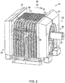
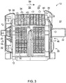
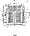
- FIGS. 1-4 some aspects of non-limiting examples of a machine system 10, which does not form part of the present invention are illustrated.
- FIG. 1 depicts a machine system
- FIG. 2 depicts another machine system, wherein a scavenge scoop (described below) has a different shape than that of FIG. 1 .
- FIG. 3 illustrates a partial cut-away view of the machine system of FIG. 1 ; and
- FIG. 4 illustrates a partial cut-away view of the machine system of FIG. 3 .
- Machine system 10 includes a machine in the form of a gearbox 12.
- gearbox 12 is a gear reducer, i.e., a speed-reducing gearbox.
- gearbox 12 may be a speed-increasing gearbox.
- gearbox 12 may be another type of gearbox.
- Gearbox 12 has an external surface 14.
- Machine system 10 includes a cooling airflow generator 16, a shroud 18, and a scavenge scoop 24.
- Gearbox 12 includes a first shaft or an input shaft 20 and a second shaft or an output shaft 22.
- external surface 14 includes a plurality of cooling fins 26.
- external surface 14 may include other heat transfer features, e.g., pin fins or other features that increase convective heat transfer from external surface 14.
- external surface 14 may not include any fins, pin fins or other surface features that increase convective heat transfer.
- Input shaft 20 extends from an input face or side 28 of gearbox 12.
- Output shaft 22 extends from an output face or side 30 of gearbox 12. Side 30 spaced apart from side 28.
- side 30 is opposite from and is parallel or substantially parallel to side 28.
- the rotational speed of output shaft 22 is less than the rotational speed of input shaft 20.
- output shaft 22 is operative to rotate in proportion to a rotation of input shaft 20.
- the cooling airflow generator 16 is mounted on or coupled to input shaft 20. Input shaft 20 is operative to rotate cooling airflow generator 16.
- the cooling airflow generator 16 may alternatively be powered by another shaft, drive system or motor.
- cooling airflow generator 16 is a fan, e.g., a radial or centrifugal fan, and/or an axial fan or an impeller. In other embodiments, cooling airflow generator 16 may take other forms.
- Cooling airflow generator 16 is constructed to, when rotated, draw in air from the environment 32 in which gearbox 12 is located, and generate a cooling airflow 34 using the air drawn in from environment 32.
- Cooling airflow generator 16 is operative to supply cooling airflow 34 from side 28 for cooling gearbox 12, i.e., to supply cooling airflow 34 for cooling gearbox 12 using air drawn from the environment 32 in the vicinity of side 28 by cooling airflow generator 16.
- Shroud 18 is in fluid communication with cooling air generator 16.
- Shroud 18 is constructed to receive the cooling airflow 34 from cooling air generator 16, and to direct the cooling airflow 34 received from cooling airflow generator 16 across a portion of side 28 of gearbox 12 and subsequently in a direction 39 across external surface 14, e.g., an axial direction, and to extract heat from external surface 14 by convection, thereby cooling gearbox 12.
- Shroud 18 extends beyond external surface 14, e.g., and beyond cooling fins 26 as well, for embodiments so equipped.
- Scavenge scoop 24 is spaced apart from shroud 18 by external surface 14 (and cooling fins 26, for embodiments so equipped), and is disposed at side 30 of gearbox 12 opposite to side 28 and opposite to shroud 18.
- External surface 14 has an end 36 disposed proximate to the side 28, and has an end 38 opposite and spaced apart from end 36. End 38 is disposed proximate to side 30.
- Shroud 18 is disposed proximate to end 36 of external surface 14.
- Scavenge scoop 24 is disposed proximate to end 38 of external surface 14, and in particular, has an inlet 40 disposed proximate to the end 38.
- External surface 14 is disposed or is predominantly disposed between scavenge scoop 24 and shroud 18.
- Scavenge scoop 24 is constructed to collect at least a portion of the cooling airflow 34 generated by cooling airflow generator 16 and discharged from shroud 18, and to direct this portion of the cooling airflow 34 across side 30 of gearbox 12 or at least a portion of side 30.
- inlet 40 of scavenge scoop 24 is constructed to collect at least a portion of cooling airflow 34 after the cooling airflow 34 has passed over external surface 14 (and over/through cooling fins 26 in embodiments so equipped) unbounded.
- cooling airflow 34 is not bounded or constrained or guided by a surface or flow guide structure as it flows between shroud 18 and scavenge scoop 24, and flows over and cools external surface 14 or most of external surface 14 (and cooling fins 26 in embodiments so equipped), prior to being collected or captured by scavenge scoop 24.
- cooling airflow 34 is unbounded as it travels across external surface 14 and cooling fins 26 between shroud 18 and scavenge scoop 24.
- scavenge scoop 24 extends beyond the top surface and fore and aft portions of external surface 14 and cooling fins 26 of gearbox 12 (e.g., as depicted in the illustrations of FIGS. 1-4 ), and more so than shroud 18 extends beyond those portions of external surface 14, e.g., as illustrated in FIGS. 1 and 3 .
- Scavenger scoop 24 is also constructed to direct this portion of cooling airflow 34 over output shaft 22. Scavenge scoop 24 is thus shaped to facilitate a redirection of cooling airflow 34 across output face or side 30 and output shaft 22. As illustrated in FIGS. 1 and 3 , scavenge scoop 24 employs a curved surface to smoothly transition the cooling airflow from an axial direction 39 across external surface 14 to a radially inward direction across side 30 and then axially outward and along output shaft 22. As illustrated in FIGS. 2 and 4 accomplishes the same or similar redirection of cooling airflow 34 using a scavenge scoop 24 having cylindrical, conical and flat sections. Output shaft 22 can carry a large gear that makes contact with sump oil in gearbox 12. Directing cooling airflow 34 across output shaft 22 thus effectively transfers heat from inside gearbox 12 to the environment 32 outside gearbox 12.
- the machine system of FIGS. 1 and 3 include a scavenge scoop 24 having a concave cross-section, e.g., a concave portion 33 that is concave toward external surface 14 and side 30, e.g., when viewed in a plane aligned with input shaft 20 and/or output shaft 22 (e.g., a plane parallel to axial direction 39).
- the machine system of FIGS. 2 and 4 include a scavenge scoop 24 having a substantially effective concave cross-section toward external surface 14 and side 30 when viewed in a plane aligned with input shaft 20 and/or output shaft 22.
- scavenge scoop 24 decreases the cross-sectional flow area in the flow direction, and accelerates the cooling airflow 34 collected by scavenge scoop 24, which increases the convective heat transfer from side 30 and output shaft 22.
- FIGS. 5-7 some aspects of a non-limiting example of another embodiment of machine system 10 are illustrated in accordance with an embodiment of the present invention.
- FIG. 5 illustrates a perspective view
- FIG. 6 illustrates a partial cut-away view
- FIG. 7 illustrates a partial cross-sectional view.
- machine system 10 includes a plurality of rotating suctioning fin blades 42 mounted on output shaft 22.
- Rotating suctioning fin blades 42 are in thermal engagement with output shaft 22.
- rotating suctioning fin blades 42 are integrally formed or affixed together, and are mounted on output shaft 22 with an interference fit or a taper fit.
- Rotating suctioning fin blades 42 are constructed to increase the convective surface area of output shaft 22, and to draw cooling air through rotating suctioning fin blades 42, and in some embodiments, e.g., as described herein, through scavenge scoop 24, and discharge the cooling air outside of gearbox 12.
- Rotating suctioning fin blades 42 are referred to as "fins” because they are constructed as and function as cooling fins, conducting heat away from output shaft 22 and convecting the heat to cooling air.
- Rotating suctioning fin blades 42 are referred to as 'rotating' and 'suctioning' fins because they are constructed to cooperate to generate a suction when rotated together, e.g., as a unit.
- Rotating suctioning fin blades 42 are referred to as 'blades' because they form the blades of a fan or impeller that impart motion to a fluid such as air, to generate an airflow, e.g., wherein the fan or impeller is a radial fan or impeller in some embodiments, or an axial fan or combined axial/radial fan in other embodiments.
- Rotating suctioning fin blades 42 are constructed to extract heat from output shaft 22 via conduction, and to transfer the heat to the environment 32 in which gearbox 12 is located by convection.
- rotating suctioning fin blades 42 are oriented along the axis of output shaft 22 (i.e., wherein the base of each rotating suctioning fin blade 42 extends in an axial direction, e.g., direction 39, along the axis of rotation of output shaft 22).
- rotating suctioning fin blades 42 may be oriented differently.
- rotating suctioning fin blades 42 extend in the axial direction 39, and in the radial direction, i.e., radially outward from output shaft 22.
- rotating suctioning fin blades 42 may also extend in other directions, e.g., in the circumferential direction.
- Rotating suctioning fin blades 42 are constructed to cooperate to form a fan 44, e.g., a fan, e.g., a radial or centrifugal fan, and/or an axial fan or an impeller.
- fan 44 may include a back plate 45 and a hub ring 47 that secure rotating suctioning fin blades 42 together.
- back plate 45 and hub ring 47 may be integral with rotating suctioning fin blades 42, yielding fan 44 as an integral unitary structure.
- rotating suctioning fin blades 42, back plate 45 and hub ring 47 may be affixed together.
- back plate 45 is constructed to extract heat from output shaft 22 by conduction, e.g., through hub ring 47, and to transfer the heat to the environment 32 by convection.
- Rotating suctioning fin blades 42, fan 44, back plate 45 and hub ring 47 may be formed out of, for example, aluminum, e.g., 6000 series aluminum, although other types of aluminum and/or other materials may be employed in other embodiments.
- Fan 44 e.g., an inlet or intake portion of fan 44, is in fluid communication with an outlet 46 of scavenge scoop 24.
- Output shaft 22 is operative to rotate fan 44.
- Fan 44 is constructed to, when rotated, generate a suction pressure acting on outlet 46 of scavenge scoop 24, drawing air through scavenge scoop 24.
- the air is received in inlet 40 of scavenge scoop 24.
- Scavenge scoop 24 guides the air across a portion of external surface 14 in the vicinity of end 38, inward (e.g., radially inward) and across side 30 of gearbox 12, and then radially outward through fan 44, along rotating suctioning fin blades 42 and back plate 45, providing convection cooling to side 30, and also extracting heat by convection from rotating suctioning fin blades 42 and back plate 45.
- scavenge scoop 24 is configured to entrain additional cooling airflow from the environment 32 surrounding gearbox 12.
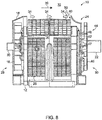
- FIG. 8 some aspects of a non-limiting example of another embodiment of machine system 10 are illustrated in accordance with an embodiment of the present invention.
- the embodiment of FIG. 8 includes, like the embodiment of FIGS. 5-7 , a plurality of rotating suctioning fin blades 42 are constructed to form fan 44.
- fan 44 includes back plate 45 and hub ring 47.
- Fan 44 is in fluid communication with outlet 46 of scavenge scoop 24.
- Output shaft 22 is operative to rotate fan 44.
- Fan 44 is constructed to, when rotated, generate a suction pressure acting on outlet 46 of scavenge scoop 24, drawing air through scavenge scoop 24. The air is received in inlet 40 of scavenge scoop 24.
- inlet 40 of scavenge scoop 24 is convex toward external surface 14 (and cooling fins 26 for embodiments so equipped), i.e., includes a convex inlet portion 48.
- scavenge scoop 24 is constructed scoop is constructed, e.g., via convex inlet portion 48, to entrain additional cooling airflow 50 from the environment 32 in which gearbox 12 is located.
- scavenge scoop 24 is constructed, e.g., via convex inlet portion 48, to entrain additional cooling airflow 50.
- additional cooling airflow 50 is entrained by the cooling airflow 34 stream into inlet 40.
- Scavenge scoop 24 guides the air (cooling airflow 34 and additional cooling airflow 50) across a portion of external surface 14 in the vicinity of end 38, inward (e.g., radially inward) and across side 30 of gearbox 12, and then radially outward through fan 44, along rotating suctioning fin blades 42 and back plate 45, providing convection cooling to side 30, and also extracting heat by convection from rotating suctioning fin blades 42 and back plate 45.
- Additional cooling airflow 50 is cooler than cooling airflow 34, e.g., because it has not absorbed heat from external surface 14 (and cooling fins 26, for embodiments so equipped). The combination of cooling airflow 34 and additional cooling airflow 50 is thus cooler than cooling airflow 34, and thus provides greater cooling to gearbox 12 than embodiments wherein cooling airflow 34 is not used to entrain additional cooling airflow 50.
- a system which does not form part of the invention may comprise: a machine having an external surface and a first shaft extending from a first side of the machine; a cooling airflow generator mounted on the shaft and operative to generate a cooling airflow; a flow guide structure in fluid communication with the cooling air generator and constructed to receive the cooling airflow from the cooling airflow generator and to direct the cooling airflow across the external surface; and a scavenge scoop spaced apart from the flow guide structure and disposed at a second side of the machine opposite the first side, wherein the external surface is disposed between the scavenge scoop and the flow guide structure, and wherein the scavenge scoop is constructed to collect a portion of the cooling airflow generated by the cooling airflow generator and direct the portion of the cooling airflow across a portion of the second side of the machine.
- the external surface has a first end disposed proximate to the first side; wherein the flow guide structure is disposed proximate to the first end; wherein the external surface has a second end opposite the first end and disposed proximate to the second side; and wherein the scavenge scoop has an inlet disposed proximate to the second end of the external surface.
- the inlet is constructed to collect the portion of the cooling airflow after the portion of the cooling airflow has passed over the external surface unbounded and cooled the external surface.
- the inlet is convex toward the external surface.
- the scavenge scoop is constructed to entrain additional cooling airflow from the environment in which the machine is located.
- the scavenge scoop is concave toward the external surface.
- the system further comprises a second shaft extending from the second side of the machine, wherein the second shaft is operative to rotate upon a rotation of the first shaft; and a plurality of rotatable suction fins in thermal engagement with the second shaft, wherein the second shaft is operative to rotate the plurality of rotatable suction fins; wherein the plurality of rotatable suction fins is constructed to generate a suction pressure acting on the scavenge scoop; and wherein the plurality of rotatable suction fins are operative to extract heat from the second shaft via conduction.
- the machine is a gear reducer; wherein the first shaft is an input shaft; and wherein the second shaft is an output shaft.
- the rotatable suction fins are constructed to increase the convective surface area of the second shaft.
- the surface includes a plurality of cooling fins.
- a system which does not form part of the invention may comprise: a gearbox having an external surface and an input shaft extending from a first side of the gearbox; a fan or impeller coupled to the input shaft, the fan or impeller being operative to, when rotated by the input shaft, generate a cooling airflow; a shroud constructed to guide the cooling airflow from the fan or impeller and direct the cooling airflow across the external surface and extract heat from the external surface by convection; and a scavenge scoop spaced apart from the shroud and disposed at a second side of the gearbox opposite the first side and opposite the shroud, wherein the external surface is disposed between the scavenge scoop and the shroud, and wherein the scavenge scoop is constructed to collect a portion of the cooling airflow generated by the cooling airflow generator and to direct the portion of the cooling airflow across a portion of the second side of the gearbox.
- the external surface has a first end disposed proximate to the first side; wherein the shroud is disposed proximate to the first end; wherein the external surface has a second end opposite the first end and disposed proximate to the second side; and wherein the scavenge scoop has an inlet disposed proximate to the second end of the external surface.
- the inlet is constructed to collect the portion of the cooling airflow after the portion of the cooling airflow has passed over the external surface unbounded and cooled the external surface.
- the inlet is convex toward the external surface.
- the scavenge scoop is constructed to entrain additional cooling airflow from the environment in which the gearbox is located.
- the scavenge scoop is concave toward the external surface.
- system further comprises an output shaft extending from the second side of the gearbox, wherein the output shaft is operative to rotate in a proportion to a rotation of the input shaft; and a plurality of rotatable suction fins mounted on and in thermal engagement with the output shaft; wherein the plurality of rotatable suction fins are constructed to extract heat from the output shaft via conduction
- the scavenge scoop has an outlet; wherein the plurality of rotatable suction fins are in fluid communication with the outlet and are constructed to, when rotated, generate a suction pressure acting on the outlet and drawing air through the scavenge scoop, across the second side and through the rotatable suction fins to provide convection cooling to the second side and the rotatable suction fins.
- the gearbox is a gear reducer.
- the rotatable suction fins are constructed to increase the convective surface area of the second shaft.
Landscapes
- Engineering & Computer Science (AREA)
- General Engineering & Computer Science (AREA)
- Mechanical Engineering (AREA)
- Power Engineering (AREA)
- Physics & Mathematics (AREA)
- Thermal Sciences (AREA)
- General Details Of Gearings (AREA)
Claims (11)
- Maschinensystem (10), das umfasst:eine Maschine (12) mit einer Außenfläche (14) und einer ersten Welle (20), die sich von einer ersten Seite (28) der Maschine (12) erstreckt, wobei die Maschine (12) ein Getriebe ist und wobei die erste Welle (20) eine Antriebswelle ist;einen Kühlluftstromgenerator (16), der auf der ersten Welle (20) montiert und dazu eingerichtet ist, einen Kühlluftstrom (34) zur Kühlung der Maschine (12) zu erzeugen;eine Strömungsführungsstruktur (18), die in Fluidkommunikation mit dem Kühlluftstromgenerator (16) steht und so konstruiert ist, dass sie den Kühlluftstrom (34) von dem Kühlluftstromgenerator (16) empfängt und den Kühlluftstrom (34) in eine Richtung über die Außenfläche (14) lenkt;eine Rücklaufschaufel (24), die von der Strömungsführungsstruktur (18) beabstandet und an einer zweiten Seite (30) der Maschine (12) gegenüber der ersten Seite (28) angeordnet ist, wobei die Außenfläche (14) zwischen der Rücklaufschaufel (24) und der Strömungsführungsstruktur (18) angeordnet ist, und wobei die Rücklaufschaufel (24) so konstruiert ist, dass sie einen Teil des von dem Kühlluftstromgenerator (16) erzeugten Kühlluftstroms (34) sammelt und den Teil des Kühlluftstroms (34) über einen Abschnitt der zweiten Seite (30) der Maschine (12) leitet; undeine zweite Welle (22), die sich von der zweiten Seite (30) der Maschine (12) erstreckt, wobei die zweite Welle (22) dazu eingerichtet ist, sich bei einer Drehung der ersten Welle (20) zu drehen und wobei die zweite Welle (22) eine Abtriebswelle ist;dadurch gekennzeichnet, dass das Maschinensystem (10) ferner umfasst:
eine Mehrzahl von rotierenden Saugrippenschaufeln (42) in thermischem Eingriff mit der zweiten Welle (22), wobei die zweite Welle (22) dazu eingerichtet ist, die Mehrzahl von rotierenden Saugrippenschaufeln (42) zu drehen, wobei die Mehrzahl von rotierenden Saugrippenschaufeln (42) so konstruiert ist, dass sie einen Saugdruck erzeugen, der auf einen Auslass (46) der Rücklaufschaufel (24) wirkt, und wobei die Mehrzahl von rotierenden Saugrippenschaufeln (42) dazu eingerichtet sind, durch Leitung von der zweiten Welle (22) Wärme abzuführen. - Maschinensystem (10) nach Anspruch 1, wobei die Außenfläche (14) ein erstes Ende (36) aufweist, das benachbart zu der ersten Seite (28) angeordnet ist; wobei die Strömungsführungsstruktur (18) benachbart zu dem ersten Ende (36) angeordnet ist; wobei die Außenfläche (14) ein zweites Ende (38) aufweist, das dem ersten Ende (36) gegenüberliegt und benachbart zu der zweiten Seite (30) angeordnet ist; und wobei die Rücklaufschaufel (24) einen Einlass (40) aufweist, der benachbart zu dem zweiten Ende (38) der Außenfläche (14) angeordnet ist.
- Maschinensystem (10) nach Anspruch 1, wobei die Außenfläche (14) eine Mehrzahl von Kühlrippen (26) aufweist.
- Maschinensystem (12) nach Anspruch 1, wobei:das Getriebe (12) ist ein Untersetzungsgetriebe;der Kühlluftstromgenerator (16) ein Ventilator oder ein Gebläserad ist;die Strömungsführungsstruktur (18) eine Verkleidung ist, die so konstruiert ist, dass sie den Kühlluftstrom (34) von dem Ventilator oder dem Gebläserad (16) führt und durch Konvektion Wärme von der Außenfläche (14) abführt; unddie Rücklaufschaufel (24) auf der zweiten Seite (30) gegenüber der Verkleidung (18) angeordnet ist.
- Maschinensystem (10) nach Anspruch 4, wobei die Außenfläche (14) ein erstes Ende (36) aufweist, das benachbart zu der ersten Seite (28) angeordnet ist; wobei die Verkleidung (18) benachbart zu dem ersten Ende (36) angeordnet ist; wobei die Außenfläche (14) ein zweites Ende (38) aufweist, das dem ersten Ende (36) gegenüberliegt und benachbart zu der zweiten Seite (30) angeordnet ist; und wobei die Rücklaufschaufel (24) einen Einlass (40) aufweist, der benachbart zu dem zweiten Ende (38) der Außenfläche (14) angeordnet ist.
- Maschinensystem (10) nach Anspruch 2 oder 5, wobei der Einlass (40) so konstruiert ist, dass er den Teil des Kühlluftstroms (34) sammelt, nachdem der Teil des Kühlluftstroms (34) über die Außenfläche (14) geströmt ist und die Außenfläche (14) gekühlt hat.
- Maschinensystem (10) nach Anspruch 2 oder 5, wobei der Einlass (40) in Richtung der Außenfläche (14) konvex ist.
- Maschinensystem (10) nach Anspruch 1 oder 4, wobei die Rücklaufschaufel (24) so konstruiert ist, dass sie einen zusätzlichen Kühlluftstrom aus der Umgebung (32), in der sich die Maschine (12) befindet, mitführt.
- Maschinensystem (10) nach Anspruch 1 oder 4, wobei die Rücklaufschaufel (24) in Richtung der Außenfläche (14) konkav ist.
- Maschinensystem nach Anspruch 4, wobei die Mehrzahl von rotierenden Saugrippenschaufeln (42) in Fluidkommunikation mit dem Auslass (46) stehen und so konstruiert sind, dass sie, wenn sie gedreht werden, den Saugdruck erzeugen, der auf den Auslass (46) wirkt und Luft durch die Rücklaufschaufel, über die zweite Seite (30) und durch die rotierenden Saugrippenschaufeln (42) zieht, um eine Konvektionskühlung der zweiten Seite (30) und der rotierenden Saugrippenschaufeln (42) bereitzustellen.
- Maschinensystem (10) nach Anspruch 4, wobei die rotierenden Saugrippenschaufeln (42) so konstruiert sind, dass sie die konvektive Oberfläche der zweiten Welle (22) vergrößern.
Applications Claiming Priority (1)
| Application Number | Priority Date | Filing Date | Title |
|---|---|---|---|
| US15/994,456 US10578205B2 (en) | 2018-05-31 | 2018-05-31 | Machine and gearbox system with air cooling |
Publications (2)
| Publication Number | Publication Date |
|---|---|
| EP3576263A1 EP3576263A1 (de) | 2019-12-04 |
| EP3576263B1 true EP3576263B1 (de) | 2020-11-11 |
Family
ID=66685463
Family Applications (1)
| Application Number | Title | Priority Date | Filing Date |
|---|---|---|---|
| EP19177705.1A Not-in-force EP3576263B1 (de) | 2018-05-31 | 2019-05-31 | Maschine und getriebesystem mit luftkühlung |
Country Status (2)
| Country | Link |
|---|---|
| US (1) | US10578205B2 (de) |
| EP (1) | EP3576263B1 (de) |
Families Citing this family (8)
| Publication number | Priority date | Publication date | Assignee | Title |
|---|---|---|---|---|
| US11466768B2 (en) | 2018-12-31 | 2022-10-11 | Abb Schweiz Ag | Methods and systems for cooling transmissions |
| US11287025B2 (en) | 2018-12-31 | 2022-03-29 | Abb Schweiz Ag | Cooling units for transmissions |
| CN113614413B (zh) * | 2019-03-26 | 2024-02-09 | 索尤若驱动有限及两合公司 | 具有风机装置的减速器 |
| US11174937B2 (en) * | 2019-09-23 | 2021-11-16 | Abb Schweiz Ag | Speed reducer cooling fins and method of manufacturing |
| GB202019212D0 (en) * | 2020-12-07 | 2021-01-20 | J And M Ferranti Tech Limited | Propulsion systems for aircraft |
| DE102021206105A1 (de) * | 2021-06-15 | 2022-12-15 | Dana Motion Systems Deutschland GmbH | Lüfterabdeckungsbaugruppe für ein Getriebe, Verfahren zu deren Herstellung, Baugruppe und modularer Satz |
| EP4124781A1 (de) | 2021-07-26 | 2023-02-01 | Flender GmbH | Bauraumsparende getriebekühleinrichtung und getriebe |
| CN113669436A (zh) * | 2021-07-27 | 2021-11-19 | 南京航空航天大学 | 一种用于齿轮箱强化传热的周向螺旋水槽冷却装置 |
Family Cites Families (7)
| Publication number | Priority date | Publication date | Assignee | Title |
|---|---|---|---|---|
| DE1715971U (de) | 1953-07-23 | 1956-02-02 | Bbc Brown Boveri & Cie | Elektrische maschine gekapselter bauart. |
| DE1128023B (de) | 1960-08-03 | 1962-04-19 | Siemens Ag | Einrichtung zur Oberflaechenkuehlung von umlaufenden Maschinen, insbesondere Elektromotoren und Generatoren |
| DE1298819B (de) | 1966-07-21 | 1969-07-03 | Wuelfel Eisenwerk | Kuehlvorrichtung fuer Umlaufraedergetriebe |
| JP2002218704A (ja) | 2001-01-22 | 2002-08-02 | Mitsubishi Electric Corp | 全閉外扇形電動機 |
| JP6063288B2 (ja) * | 2013-02-15 | 2017-01-18 | 住友重機械工業株式会社 | 動力伝達装置 |
| JP2014196768A (ja) | 2013-03-29 | 2014-10-16 | 住友重機械工業株式会社 | 減速機 |
| US20170211478A1 (en) * | 2014-04-11 | 2017-07-27 | Unison Industries, Llc | Tubular cooler with integrated fan |
-
2018
- 2018-05-31 US US15/994,456 patent/US10578205B2/en not_active Expired - Fee Related
-
2019
- 2019-05-31 EP EP19177705.1A patent/EP3576263B1/de not_active Not-in-force
Non-Patent Citations (1)
| Title |
|---|
| None * |
Also Published As
| Publication number | Publication date |
|---|---|
| EP3576263A1 (de) | 2019-12-04 |
| US10578205B2 (en) | 2020-03-03 |
| US20190368596A1 (en) | 2019-12-05 |
Similar Documents
| Publication | Publication Date | Title |
|---|---|---|
| EP3576263B1 (de) | Maschine und getriebesystem mit luftkühlung | |
| US7157818B2 (en) | Low noise ventilation system for electric motor | |
| RU2502179C2 (ru) | Электрическая машина с двойным осевым вентилятором | |
| RU2651909C2 (ru) | Воздухоочиститель и воздуходувное устройство для него | |
| US6435828B1 (en) | Split blade radial fan | |
| CN108368852B (zh) | 涡轮发动机或航空器的电动离心式压缩机 | |
| US6309178B1 (en) | Downstream guiding device for fan-radiator cooling system | |
| EP2712805B1 (de) | System und Verfahren zum Kühlen des Getriebes eines schwebefähigen Luftfahrzeugs | |
| JP2017089635A (ja) | 航空機エンジン流体を冷却する方法及びシステム | |
| EP2361455B1 (de) | Schleifringbaugruppe mit kühlung | |
| EP3872349A1 (de) | Gebläse mit verjüngtem element zwischen einlass und motor | |
| US8585374B2 (en) | Fan motor cooling with primary and secondary air cooling paths | |
| CN108884756B (zh) | 带转子冷却功能的充电装置 | |
| EP0651161B1 (de) | Kühlvorrichtung für einen Elektromotor eines Turbolüfters | |
| US20190101122A1 (en) | Diagonal fan | |
| EP0074068B1 (de) | Vorrichtung zur Kühlung von Wechselstromgeneratoren für Kraftfahrzeuge | |
| US9939058B2 (en) | Gearbox having gear baffle apparatus | |
| SE527867C2 (sv) | Kylanordning | |
| US5509830A (en) | Marine propulsor cooling and lubricating system | |
| KR102495740B1 (ko) | 임펠러 | |
| JP2012026303A (ja) | 排気ターボ過給機における潤滑油の排出装置 | |
| CN221305640U (zh) | 一种高速电机 | |
| JP2018527182A (ja) | 固体ボウルスクリュ遠心分離機の駆動部用の冷却デバイス | |
| CN115514150B (zh) | 一种应用于吸尘器的外转子电机 | |
| EP4617504A1 (de) | Laufrad und reiniger damit |
Legal Events
| Date | Code | Title | Description |
|---|---|---|---|
| PUAI | Public reference made under article 153(3) epc to a published international application that has entered the european phase |
Free format text: ORIGINAL CODE: 0009012 |
|
| STAA | Information on the status of an ep patent application or granted ep patent |
Free format text: STATUS: REQUEST FOR EXAMINATION WAS MADE |
|
| 17P | Request for examination filed |
Effective date: 20190531 |
|
| AK | Designated contracting states |
Kind code of ref document: A1 Designated state(s): AL AT BE BG CH CY CZ DE DK EE ES FI FR GB GR HR HU IE IS IT LI LT LU LV MC MK MT NL NO PL PT RO RS SE SI SK SM TR |
|
| AX | Request for extension of the european patent |
Extension state: BA ME |
|
| STAA | Information on the status of an ep patent application or granted ep patent |
Free format text: STATUS: EXAMINATION IS IN PROGRESS |
|
| 17Q | First examination report despatched |
Effective date: 20200403 |
|
| RIC1 | Information provided on ipc code assigned before grant |
Ipc: F16H 57/04 20100101ALI20200609BHEP Ipc: F16H 57/02 20120101ALN20200609BHEP Ipc: H02K 9/14 20060101AFI20200609BHEP |
|
| GRAP | Despatch of communication of intention to grant a patent |
Free format text: ORIGINAL CODE: EPIDOSNIGR1 |
|
| STAA | Information on the status of an ep patent application or granted ep patent |
Free format text: STATUS: GRANT OF PATENT IS INTENDED |
|
| RIC1 | Information provided on ipc code assigned before grant |
Ipc: F16H 57/04 20100101ALI20200629BHEP Ipc: F16H 57/02 20120101ALN20200629BHEP Ipc: H02K 9/14 20060101AFI20200629BHEP |
|
| INTG | Intention to grant announced |
Effective date: 20200721 |
|
| GRAS | Grant fee paid |
Free format text: ORIGINAL CODE: EPIDOSNIGR3 |
|
| GRAA | (expected) grant |
Free format text: ORIGINAL CODE: 0009210 |
|
| STAA | Information on the status of an ep patent application or granted ep patent |
Free format text: STATUS: THE PATENT HAS BEEN GRANTED |
|
| AK | Designated contracting states |
Kind code of ref document: B1 Designated state(s): AL AT BE BG CH CY CZ DE DK EE ES FI FR GB GR HR HU IE IS IT LI LT LU LV MC MK MT NL NO PL PT RO RS SE SI SK SM TR |
|
| RAP1 | Party data changed (applicant data changed or rights of an application transferred) |
Owner name: ABB SCHWEIZ AG |
|
| REG | Reference to a national code |
Ref country code: GB Ref legal event code: FG4D |
|
| REG | Reference to a national code |
Ref country code: CH Ref legal event code: EP |
|
| REG | Reference to a national code |
Ref country code: AT Ref legal event code: REF Ref document number: 1334385 Country of ref document: AT Kind code of ref document: T Effective date: 20201115 |
|
| REG | Reference to a national code |
Ref country code: DE Ref legal event code: R096 Ref document number: 602019001269 Country of ref document: DE |
|
| REG | Reference to a national code |
Ref country code: IE Ref legal event code: FG4D |
|
| REG | Reference to a national code |
Ref country code: NL Ref legal event code: MP Effective date: 20201111 |
|
| REG | Reference to a national code |
Ref country code: AT Ref legal event code: MK05 Ref document number: 1334385 Country of ref document: AT Kind code of ref document: T Effective date: 20201111 |
|
| PG25 | Lapsed in a contracting state [announced via postgrant information from national office to epo] |
Ref country code: GR Free format text: LAPSE BECAUSE OF FAILURE TO SUBMIT A TRANSLATION OF THE DESCRIPTION OR TO PAY THE FEE WITHIN THE PRESCRIBED TIME-LIMIT Effective date: 20210212 Ref country code: NO Free format text: LAPSE BECAUSE OF FAILURE TO SUBMIT A TRANSLATION OF THE DESCRIPTION OR TO PAY THE FEE WITHIN THE PRESCRIBED TIME-LIMIT Effective date: 20210211 Ref country code: FI Free format text: LAPSE BECAUSE OF FAILURE TO SUBMIT A TRANSLATION OF THE DESCRIPTION OR TO PAY THE FEE WITHIN THE PRESCRIBED TIME-LIMIT Effective date: 20201111 Ref country code: PT Free format text: LAPSE BECAUSE OF FAILURE TO SUBMIT A TRANSLATION OF THE DESCRIPTION OR TO PAY THE FEE WITHIN THE PRESCRIBED TIME-LIMIT Effective date: 20210311 Ref country code: RS Free format text: LAPSE BECAUSE OF FAILURE TO SUBMIT A TRANSLATION OF THE DESCRIPTION OR TO PAY THE FEE WITHIN THE PRESCRIBED TIME-LIMIT Effective date: 20201111 |
|
| PG25 | Lapsed in a contracting state [announced via postgrant information from national office to epo] |
Ref country code: AT Free format text: LAPSE BECAUSE OF FAILURE TO SUBMIT A TRANSLATION OF THE DESCRIPTION OR TO PAY THE FEE WITHIN THE PRESCRIBED TIME-LIMIT Effective date: 20201111 Ref country code: BG Free format text: LAPSE BECAUSE OF FAILURE TO SUBMIT A TRANSLATION OF THE DESCRIPTION OR TO PAY THE FEE WITHIN THE PRESCRIBED TIME-LIMIT Effective date: 20210211 Ref country code: SE Free format text: LAPSE BECAUSE OF FAILURE TO SUBMIT A TRANSLATION OF THE DESCRIPTION OR TO PAY THE FEE WITHIN THE PRESCRIBED TIME-LIMIT Effective date: 20201111 Ref country code: PL Free format text: LAPSE BECAUSE OF FAILURE TO SUBMIT A TRANSLATION OF THE DESCRIPTION OR TO PAY THE FEE WITHIN THE PRESCRIBED TIME-LIMIT Effective date: 20201111 Ref country code: IS Free format text: LAPSE BECAUSE OF FAILURE TO SUBMIT A TRANSLATION OF THE DESCRIPTION OR TO PAY THE FEE WITHIN THE PRESCRIBED TIME-LIMIT Effective date: 20210311 Ref country code: LV Free format text: LAPSE BECAUSE OF FAILURE TO SUBMIT A TRANSLATION OF THE DESCRIPTION OR TO PAY THE FEE WITHIN THE PRESCRIBED TIME-LIMIT Effective date: 20201111 |
|
| REG | Reference to a national code |
Ref country code: LT Ref legal event code: MG9D |
|
| PG25 | Lapsed in a contracting state [announced via postgrant information from national office to epo] |
Ref country code: HR Free format text: LAPSE BECAUSE OF FAILURE TO SUBMIT A TRANSLATION OF THE DESCRIPTION OR TO PAY THE FEE WITHIN THE PRESCRIBED TIME-LIMIT Effective date: 20201111 |
|
| PG25 | Lapsed in a contracting state [announced via postgrant information from national office to epo] |
Ref country code: EE Free format text: LAPSE BECAUSE OF FAILURE TO SUBMIT A TRANSLATION OF THE DESCRIPTION OR TO PAY THE FEE WITHIN THE PRESCRIBED TIME-LIMIT Effective date: 20201111 Ref country code: SM Free format text: LAPSE BECAUSE OF FAILURE TO SUBMIT A TRANSLATION OF THE DESCRIPTION OR TO PAY THE FEE WITHIN THE PRESCRIBED TIME-LIMIT Effective date: 20201111 Ref country code: SK Free format text: LAPSE BECAUSE OF FAILURE TO SUBMIT A TRANSLATION OF THE DESCRIPTION OR TO PAY THE FEE WITHIN THE PRESCRIBED TIME-LIMIT Effective date: 20201111 Ref country code: CZ Free format text: LAPSE BECAUSE OF FAILURE TO SUBMIT A TRANSLATION OF THE DESCRIPTION OR TO PAY THE FEE WITHIN THE PRESCRIBED TIME-LIMIT Effective date: 20201111 Ref country code: LT Free format text: LAPSE BECAUSE OF FAILURE TO SUBMIT A TRANSLATION OF THE DESCRIPTION OR TO PAY THE FEE WITHIN THE PRESCRIBED TIME-LIMIT Effective date: 20201111 Ref country code: RO Free format text: LAPSE BECAUSE OF FAILURE TO SUBMIT A TRANSLATION OF THE DESCRIPTION OR TO PAY THE FEE WITHIN THE PRESCRIBED TIME-LIMIT Effective date: 20201111 |
|
| REG | Reference to a national code |
Ref country code: DE Ref legal event code: R097 Ref document number: 602019001269 Country of ref document: DE |
|
| PG25 | Lapsed in a contracting state [announced via postgrant information from national office to epo] |
Ref country code: DK Free format text: LAPSE BECAUSE OF FAILURE TO SUBMIT A TRANSLATION OF THE DESCRIPTION OR TO PAY THE FEE WITHIN THE PRESCRIBED TIME-LIMIT Effective date: 20201111 |
|
| PLBE | No opposition filed within time limit |
Free format text: ORIGINAL CODE: 0009261 |
|
| STAA | Information on the status of an ep patent application or granted ep patent |
Free format text: STATUS: NO OPPOSITION FILED WITHIN TIME LIMIT |
|
| 26N | No opposition filed |
Effective date: 20210812 |
|
| PG25 | Lapsed in a contracting state [announced via postgrant information from national office to epo] |
Ref country code: NL Free format text: LAPSE BECAUSE OF FAILURE TO SUBMIT A TRANSLATION OF THE DESCRIPTION OR TO PAY THE FEE WITHIN THE PRESCRIBED TIME-LIMIT Effective date: 20201111 Ref country code: AL Free format text: LAPSE BECAUSE OF FAILURE TO SUBMIT A TRANSLATION OF THE DESCRIPTION OR TO PAY THE FEE WITHIN THE PRESCRIBED TIME-LIMIT Effective date: 20201111 |
|
| PG25 | Lapsed in a contracting state [announced via postgrant information from national office to epo] |
Ref country code: SI Free format text: LAPSE BECAUSE OF FAILURE TO SUBMIT A TRANSLATION OF THE DESCRIPTION OR TO PAY THE FEE WITHIN THE PRESCRIBED TIME-LIMIT Effective date: 20201111 |
|
| PG25 | Lapsed in a contracting state [announced via postgrant information from national office to epo] |
Ref country code: MC Free format text: LAPSE BECAUSE OF FAILURE TO SUBMIT A TRANSLATION OF THE DESCRIPTION OR TO PAY THE FEE WITHIN THE PRESCRIBED TIME-LIMIT Effective date: 20201111 Ref country code: LU Free format text: LAPSE BECAUSE OF NON-PAYMENT OF DUE FEES Effective date: 20210531 Ref country code: ES Free format text: LAPSE BECAUSE OF FAILURE TO SUBMIT A TRANSLATION OF THE DESCRIPTION OR TO PAY THE FEE WITHIN THE PRESCRIBED TIME-LIMIT Effective date: 20201111 |
|
| REG | Reference to a national code |
Ref country code: BE Ref legal event code: MM Effective date: 20210531 |
|
| PG25 | Lapsed in a contracting state [announced via postgrant information from national office to epo] |
Ref country code: IE Free format text: LAPSE BECAUSE OF NON-PAYMENT OF DUE FEES Effective date: 20210531 |
|
| PG25 | Lapsed in a contracting state [announced via postgrant information from national office to epo] |
Ref country code: IS Free format text: LAPSE BECAUSE OF FAILURE TO SUBMIT A TRANSLATION OF THE DESCRIPTION OR TO PAY THE FEE WITHIN THE PRESCRIBED TIME-LIMIT Effective date: 20210311 Ref country code: FR Free format text: LAPSE BECAUSE OF NON-PAYMENT OF DUE FEES Effective date: 20210531 |
|
| PG25 | Lapsed in a contracting state [announced via postgrant information from national office to epo] |
Ref country code: BE Free format text: LAPSE BECAUSE OF NON-PAYMENT OF DUE FEES Effective date: 20210531 |
|
| PGFP | Annual fee paid to national office [announced via postgrant information from national office to epo] |
Ref country code: IT Payment date: 20220531 Year of fee payment: 4 Ref country code: DE Payment date: 20220519 Year of fee payment: 4 |
|
| REG | Reference to a national code |
Ref country code: CH Ref legal event code: PL |
|
| PG25 | Lapsed in a contracting state [announced via postgrant information from national office to epo] |
Ref country code: LI Free format text: LAPSE BECAUSE OF NON-PAYMENT OF DUE FEES Effective date: 20220531 Ref country code: CH Free format text: LAPSE BECAUSE OF NON-PAYMENT OF DUE FEES Effective date: 20220531 |
|
| REG | Reference to a national code |
Ref country code: DE Ref legal event code: R082 Ref document number: 602019001269 Country of ref document: DE Representative=s name: MAIWALD GMBH, DE |
|
| PG25 | Lapsed in a contracting state [announced via postgrant information from national office to epo] |
Ref country code: CY Free format text: LAPSE BECAUSE OF FAILURE TO SUBMIT A TRANSLATION OF THE DESCRIPTION OR TO PAY THE FEE WITHIN THE PRESCRIBED TIME-LIMIT Effective date: 20201111 |
|
| PG25 | Lapsed in a contracting state [announced via postgrant information from national office to epo] |
Ref country code: HU Free format text: LAPSE BECAUSE OF FAILURE TO SUBMIT A TRANSLATION OF THE DESCRIPTION OR TO PAY THE FEE WITHIN THE PRESCRIBED TIME-LIMIT; INVALID AB INITIO Effective date: 20190531 |
|
| REG | Reference to a national code |
Ref country code: DE Ref legal event code: R119 Ref document number: 602019001269 Country of ref document: DE |
|
| GBPC | Gb: european patent ceased through non-payment of renewal fee |
Effective date: 20230531 |
|
| PG25 | Lapsed in a contracting state [announced via postgrant information from national office to epo] |
Ref country code: MK Free format text: LAPSE BECAUSE OF FAILURE TO SUBMIT A TRANSLATION OF THE DESCRIPTION OR TO PAY THE FEE WITHIN THE PRESCRIBED TIME-LIMIT Effective date: 20201111 Ref country code: IT Free format text: LAPSE BECAUSE OF NON-PAYMENT OF DUE FEES Effective date: 20230531 Ref country code: DE Free format text: LAPSE BECAUSE OF NON-PAYMENT OF DUE FEES Effective date: 20231201 Ref country code: GB Free format text: LAPSE BECAUSE OF NON-PAYMENT OF DUE FEES Effective date: 20230531 |
|
| PG25 | Lapsed in a contracting state [announced via postgrant information from national office to epo] |
Ref country code: MT Free format text: LAPSE BECAUSE OF FAILURE TO SUBMIT A TRANSLATION OF THE DESCRIPTION OR TO PAY THE FEE WITHIN THE PRESCRIBED TIME-LIMIT Effective date: 20201111 |
|
| PG25 | Lapsed in a contracting state [announced via postgrant information from national office to epo] |
Ref country code: TR Free format text: LAPSE BECAUSE OF FAILURE TO SUBMIT A TRANSLATION OF THE DESCRIPTION OR TO PAY THE FEE WITHIN THE PRESCRIBED TIME-LIMIT Effective date: 20201111 |