EP3576290B1 - Winkelbestimmung für einen generator - Google Patents
Winkelbestimmung für einen generator Download PDFInfo
- Publication number
- EP3576290B1 EP3576290B1 EP19171873.3A EP19171873A EP3576290B1 EP 3576290 B1 EP3576290 B1 EP 3576290B1 EP 19171873 A EP19171873 A EP 19171873A EP 3576290 B1 EP3576290 B1 EP 3576290B1
- Authority
- EP
- European Patent Office
- Prior art keywords
- generator
- terminal
- angle
- pcc
- determined
- Prior art date
- Legal status (The legal status is an assumption and is not a legal conclusion. Google has not performed a legal analysis and makes no representation as to the accuracy of the status listed.)
- Active
Links
Images


Classifications
-
- G—PHYSICS
- G01—MEASURING; TESTING
- G01D—MEASURING NOT SPECIALLY ADAPTED FOR A SPECIFIC VARIABLE; ARRANGEMENTS FOR MEASURING TWO OR MORE VARIABLES NOT COVERED IN A SINGLE OTHER SUBCLASS; TARIFF METERING APPARATUS; MEASURING OR TESTING NOT OTHERWISE PROVIDED FOR
- G01D5/00—Mechanical means for transferring the output of a sensing member; Means for converting the output of a sensing member to another variable where the form or nature of the sensing member does not constrain the means for converting; Transducers not specially adapted for a specific variable
- G01D5/12—Mechanical means for transferring the output of a sensing member; Means for converting the output of a sensing member to another variable where the form or nature of the sensing member does not constrain the means for converting; Transducers not specially adapted for a specific variable using electric or magnetic means
- G01D5/14—Mechanical means for transferring the output of a sensing member; Means for converting the output of a sensing member to another variable where the form or nature of the sensing member does not constrain the means for converting; Transducers not specially adapted for a specific variable using electric or magnetic means influencing the magnitude of a current or voltage
- G01D5/242—Mechanical means for transferring the output of a sensing member; Means for converting the output of a sensing member to another variable where the form or nature of the sensing member does not constrain the means for converting; Transducers not specially adapted for a specific variable using electric or magnetic means influencing the magnitude of a current or voltage by carrying output of an electrodynamic device, e.g. a tachodynamo
-
- H—ELECTRICITY
- H02—GENERATION; CONVERSION OR DISTRIBUTION OF ELECTRIC POWER
- H02P—CONTROL OR REGULATION OF ELECTRIC MOTORS, ELECTRIC GENERATORS OR DYNAMO-ELECTRIC CONVERTERS; CONTROLLING TRANSFORMERS, REACTORS OR CHOKE COILS
- H02P9/00—Arrangements for controlling electric generators for the purpose of obtaining a desired output
- H02P9/006—Means for protecting the generator by using control
-
- G—PHYSICS
- G01—MEASURING; TESTING
- G01R—MEASURING ELECTRIC VARIABLES; MEASURING MAGNETIC VARIABLES
- G01R31/00—Arrangements for testing electric properties; Arrangements for locating electric faults; Arrangements for electrical testing characterised by what is being tested not provided for elsewhere
- G01R31/34—Testing dynamo-electric machines
- G01R31/343—Testing dynamo-electric machines in operation
-
- H—ELECTRICITY
- H02—GENERATION; CONVERSION OR DISTRIBUTION OF ELECTRIC POWER
- H02J—ELECTRIC POWER NETWORKS; CIRCUIT ARRANGEMENTS OR SYSTEMS FOR SUPPLYING OR DISTRIBUTING ELECTRIC POWER; SYSTEMS FOR STORING ELECTRIC ENERGY
- H02J3/00—Circuit arrangements for AC mains or AC distribution networks
- H02J3/38—Arrangements for feeding a single network from two or more generators or sources in parallel; Arrangements for feeding already energised networks from additional generators or sources in parallel
- H02J3/40—Synchronisation of generators for connection to a network or to another generator
-
- H—ELECTRICITY
- H02—GENERATION; CONVERSION OR DISTRIBUTION OF ELECTRIC POWER
- H02P—CONTROL OR REGULATION OF ELECTRIC MOTORS, ELECTRIC GENERATORS OR DYNAMO-ELECTRIC CONVERTERS; CONTROLLING TRANSFORMERS, REACTORS OR CHOKE COILS
- H02P9/00—Arrangements for controlling electric generators for the purpose of obtaining a desired output
- H02P9/009—Circuit arrangements for detecting rotor position
-
- H—ELECTRICITY
- H02—GENERATION; CONVERSION OR DISTRIBUTION OF ELECTRIC POWER
- H02P—CONTROL OR REGULATION OF ELECTRIC MOTORS, ELECTRIC GENERATORS OR DYNAMO-ELECTRIC CONVERTERS; CONTROLLING TRANSFORMERS, REACTORS OR CHOKE COILS
- H02P9/00—Arrangements for controlling electric generators for the purpose of obtaining a desired output
- H02P9/14—Arrangements for controlling electric generators for the purpose of obtaining a desired output by variation of field
- H02P9/36—Arrangements for controlling electric generators for the purpose of obtaining a desired output by variation of field using armature-reaction-excited machines
Definitions
- the performance of the generator system 10 can be determined and an out-of-step condition detected depending on the operating condition.
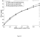
- Power factor angle is the angle between the generator terminal voltage and generator terminal current.
- the power factor angle can be determined from measurements of the generator terminal voltage and generator terminal current.
- the power factor of the generator system 10 is cos( ⁇ ).
Landscapes
- Engineering & Computer Science (AREA)
- Power Engineering (AREA)
- Physics & Mathematics (AREA)
- General Physics & Mathematics (AREA)
- Control Of Eletrric Generators (AREA)
- Tests Of Circuit Breakers, Generators, And Electric Motors (AREA)
Claims (12)
- Verfahren zum Bestimmen des Lastwinkels und/oder Rotorwinkels eines Generatorsystems (10), wobei das Generatorsystem (10) einen Generator (11) umfasst, wobei der Generator (11) ein zylindrischer Rotor ist; wobei der Generator (11) einen Generatoranschluss (15) zum Ausgeben von durch den Generator (11) erzeugter elektrischer Leistung aufweist; einen Transformator (16) und einen Anschluss eines gemeinsamen Kopplungspunktes, PCC, (17); wobei der Transformator (16) zwischen dem Generatoranschluss (15) und dem PCC-Anschluss (17) angeordnet ist; wobei der Lastwinkel definiert ist als die Winkeldifferenz zwischen der Leerlaufspannung des Generators (11) und der Spannung an dem Generatoranschluss (15) und wobei der Rotorwinkel als die Winkeldifferenz zwischen der Leerlaufspannung des Generators (11) und der Spannung an dem PCC-Anschluss (17) definiert ist; wobei das Verfahren Folgendes umfasst:Bestimmen des Feldstroms des Generators (11);Bestimmen der Ausgangsspannung von dem Generatoranschluss (15), des Ausgangsstroms von dem Generatoranschluss (15) und des Leistungsfaktorwinkels und/oder des Leistungsfaktors der Ausgangsspannung und des Ausgangsstroms von dem Generatoranschluss (15), und Bestimmen des Lastwinkels des Generatorsystems (10) in Abhängigkeit von dem ermittelten Feldstrom, der Ausgangsspannung von dem Generatoranschluss (15), dem Ausgangsstrom von dem Generatoranschluss (15) und dem Leistungsfaktorwinkel und/oder dem Leistungsfaktor der Ausgangsspannung und des Ausgangsstrom von dem Generatoranschluss (15); und/oderBestimmen der Ausgangsspannung von dem PCC-Anschluss (17), des Ausgangsstroms von dem PCC-Anschluss (17) und des Leistungsfaktorwinkels und/oder des Leistungsfaktors der Ausgangsspannung und des Ausgangsstroms von dem PCC-Anschluss (17), und Bestimmen des Rotorwinkels des Generatorsystems (10) in Abhängigkeit von dem ermittelten Feldstrom, der Ausgangsspannung von dem PCC-Anschluss (17), dem Ausgangsstrom von dem PCC-Anschluss (17) und dem Leistungsfaktorwinkel und/oder dem Leistungsfaktor der Ausgangsspannung und des Ausgangsstroms von dem PCC-Anschluss (17);wobei das Bestimmen des Lastwinkels und/oder des Rotorwinkels des Generatorsystems (10) Folgendes umfasst:Bestimmen der Leerlaufspannung des Generators (11) in Abhängigkeit von dem Feldstrom und den Leerlaufeigenschaften des Generators (11); undBestimmen des Lastwinkels und/oder des Rotorwinkels des Generatorsystems (10) in Abhängigkeit von der bestimmten Leerlaufspannung des Generators (11);wobei der Lastwinkel bestimmt wird als:
 δ der Lastwinkel ist;V_t der rms-Wert der Ausgangsspannung von dem Generatoranschluss (15) ist;I_t der rms-Wert des Ausgangsstroms von dem Generatoranschluss (15) ist;E der rms-Wert der bestimmten Leerlaufspannung ist;θ der Leistungsfaktorwinkel der Ausgangsspannung und des Ausgangsstroms von dem Generatoranschluss (15) ist; undR der Innenwiderstand des Generators (11) ist.
 - Verfahren nach Anspruch 1, wobei das Generatorsystem (10) ferner ein mechanisches Antriebssystem (12) umfasst, das angeordnet ist, um den Generator (11) anzutreiben, sodass der Generator (11) elektrische Leistung erzeugt.
- Verfahren nach einem vorhergehenden Anspruch, wobei das Bestimmen des Feldstroms des Generators (11) das Messen des Feldstroms des Generators (11) umfasst.
- Verfahren nach einem vorhergehenden Anspruch, ferner umfassend das Filtern von einem oder mehreren von der bestimmten Ausgangsspannung, des bestimmten Ausgangsstroms und des bestimmten Feldstroms, um Rauschkomponenten zu entfernen.
- Verfahren nach einem vorhergehenden Anspruch, wobei die Leerlaufeigenschaft des Generators (11) vorbestimmte Daten sind, die eines oder mehrere von berechnet, simuliert, geschätzt und gemessen worden sind.
- Verfahren nach Anspruch 5, wobei der Generator (11) ein zylindrischer Rotor ist; und der Rotorwinkel bestimmt wird als:
 δ der Rotorwinkel ist;Vp der rms-Wert der Ausgangsspannung von dem PCC-Anschluss (17) ist;Ip der rms-Wert des Ausgangsstroms von dem PCC-Anschluss (17) ist;E der rms-Wert der bestimmten Leerlaufspannung ist;θ der Leistungsfaktorwinkel der Ausgangsspannung und des Ausgangsstroms von dem PCC-Anschluss (17) ist; undR der Innenwiderstand des Generators (11) ist.
 - Verfahren nach Anspruch 5 oder 6, wobei der Generator (11) eine ausgeprägte Polmaschine ist; und der Lastwinkel bestimmt wird als:
 δ der Lastwinkel ist;Vt der rms-Wert der Ausgangsspannung von dem Anschluss (15) ist;It der rms-Wert des Ausgangsstroms von dem Anschluss (15) ist;E der rms-Wert der bestimmten Leerlaufspannung ist;θ der Leistungsfaktorwinkel der Ausgangsspannung und des Ausgangsstroms von dem Generatoranschluss (15) ist;R der Innenwiderstand des Generators (11) ist;Xd die nominale direkte synchrone Reaktanz ist; undXq die nominelle synchrone Reaktanz der Quadraturachse ist.
 - Verfahren nach einem der Ansprüche 5, 6 und 7, wobei der Generator (11) eine ausgeprägte Polmaschine ist; und der Rotorwinkel bestimmt wird als:
 δ der Rotorwinkel ist;Vp der rms-Wert der Ausgangsspannung von dem PCC-Anschluss (17) ist;Ip der rms-Wert des Ausgangsstroms von dem PCC-Anschluss (17) ist;E der rms-Wert der bestimmten Leerlaufspannung ist;θ der Leistungsfaktorwinkel der Ausgangsspannung und des Ausgangsstroms von dem PCC-Anschluss (17) ist;R der Innenwiderstand des Generators (11) ist;Xd die nominale direkte synchrone Reaktanz ist; und Xq die nominelle synchrone Reaktanz der Quadraturachse ist.
 - Verfahren zum Bestimmen, ob ein Außer-Schritt-Zustand aufgetreten ist oder nicht, wobei das Verfahren Folgendes umfasst:Bestimmen eines Lastwinkels und/oder Rotorwinkels eines Generatorsystems (10) gemäß dem Verfahren nach einem vorhergehenden Anspruch; undBestimmen, ob ein Außer-Schritt-Zustand aufgetreten ist oder nicht, in Abhängigkeit von dem bestimmten Lastwinkel und/oder Rotorwinkel.
- Generatorsystem (10), umfassend:einen Generator (11) mit einem Generatoranschluss (15) zum Ausgeben von durch den Generator (11) erzeugter elektrischer Leistung, einem Transformator (16) und einem Anschluss eines gemeinsamen Kopplungspunktes, PCC, (17), wobei der Transformator (16) zwischen dem Generatoranschluss (15) und dem PCC-Anschluss (17) angeordnet ist; undeine oder mehrere Rechenvorrichtungen (20), die konfiguriert sind, um einen Lastwinkel und/oder Rotorwinkel des Generatorsystems (10) gemäß dem Verfahren nach einem der Ansprüche 1 bis 8 und/oder einen Außer-Schritt-Zustand gemäß dem Verfahren nach Anspruch 9 zu bestimmen.
- Computerprogramm, das bei Ausfuhrung durch eine Rechenvorrichtung (20) bewirkt, dass die Rechenvorrichtung (20) einen Lastwinkel und/oder Rotorwinkel eines Generatorsystems (10) gemäß dem Verfahren nach einem der Ansprüche 1 bis 8 und/oder einen Außer-Schritt-Zustand gemäß dem Verfahren nach Anspruch 9 bestimmt.
- Rechenvorrichtung (20), die konfiguriert ist, um einen Lastwinkel und/oder Rotorwinkel eines Generatorsystems (10) und/oder einen Außer-Schritt-Zustand durch Ausführen des Computerprogramms nach Anspruch 11 zu bestimmen.
Applications Claiming Priority (1)
| Application Number | Priority Date | Filing Date | Title |
|---|---|---|---|
| GBGB1808798.1A GB201808798D0 (en) | 2018-05-30 | 2018-05-30 | Angle determination for a generator |
Publications (2)
| Publication Number | Publication Date |
|---|---|
| EP3576290A1 EP3576290A1 (de) | 2019-12-04 |
| EP3576290B1 true EP3576290B1 (de) | 2021-09-15 |
Family
ID=62812493
Family Applications (1)
| Application Number | Title | Priority Date | Filing Date |
|---|---|---|---|
| EP19171873.3A Active EP3576290B1 (de) | 2018-05-30 | 2019-04-30 | Winkelbestimmung für einen generator |
Country Status (4)
| Country | Link |
|---|---|
| US (1) | US11079255B2 (de) |
| EP (1) | EP3576290B1 (de) |
| CN (1) | CN110557065A (de) |
| GB (1) | GB201808798D0 (de) |
Families Citing this family (1)
| Publication number | Priority date | Publication date | Assignee | Title |
|---|---|---|---|---|
| CN111082717B (zh) * | 2020-02-06 | 2022-05-03 | 浙江大华技术股份有限公司 | 一种步进电机控制方法及装置 |
Family Cites Families (44)
| Publication number | Priority date | Publication date | Assignee | Title |
|---|---|---|---|---|
| US4467267A (en) | 1983-01-28 | 1984-08-21 | Sundstrand Corporation | Alternator excitation system |
| US4772802A (en) | 1987-08-19 | 1988-09-20 | Sundstrand Corporation | Starting/generating system |
| US4868406A (en) | 1988-07-05 | 1989-09-19 | Sundstrand Corporation | Electrically compensated constant speed drive with prime mover start capability |
| US4994684A (en) | 1989-01-30 | 1991-02-19 | The State Of Oregon Acting By And Through The State Board Of Higher Education On Behalf Of Oregon State University | Doubly fed generator variable speed generation control system |
| US5015941A (en) | 1989-10-30 | 1991-05-14 | Sundstrand Corporation | Power conversion system with bi-directional power converter having prime mover start capability |
| US5013929A (en) | 1989-11-22 | 1991-05-07 | Sundstrand Corporation | Power conversion system having prime mover start capability |
| US5068590A (en) | 1989-12-20 | 1991-11-26 | Sundstrand Corporation | Brushless generator having AC excitation in generating and starting modes |
| US5140245A (en) | 1990-09-24 | 1992-08-18 | Westinghouse Electric Corp. | Pmg-based position sensor and synchronous drive incorporating same |
| US5083039B1 (en) * | 1991-02-01 | 1999-11-16 | Zond Energy Systems Inc | Variable speed wind turbine |
| US5418446A (en) | 1993-05-10 | 1995-05-23 | Hallidy; William M. | Variable speed constant frequency synchronous electric power generating system and method of using same |
| US5384527A (en) | 1993-05-12 | 1995-01-24 | Sundstrand Corporation | Rotor position detector with back EMF voltage estimation |
| US5493200A (en) | 1993-05-12 | 1996-02-20 | Sundstrand Corporation | Control for a brushless generator |
| US5495163A (en) | 1993-05-12 | 1996-02-27 | Sundstrand Corporation | Control for a brushless generator operable in generating and starting modes |
| US5461293A (en) | 1993-05-12 | 1995-10-24 | Sundstrand Corporation | Rotor position detector |
| US5495162A (en) | 1993-05-12 | 1996-02-27 | Sundstrand Corporation | Position-and-velocity sensorless control for starter generator electrical system using generator back-EMF voltage |
| US5430362A (en) | 1993-05-12 | 1995-07-04 | Sundstrand Corporation | Engine starting system utilizing multiple controlled acceleration rates |
| US6172498B1 (en) | 1998-09-29 | 2001-01-09 | Rockwell Technologies, Llc | Method and apparatus for rotor angle detection |
| JP3578959B2 (ja) | 2000-02-24 | 2004-10-20 | 松下電器産業株式会社 | テーブルタップおよびテーブルタップを用いた監視システム |
| JP3587300B2 (ja) | 2001-01-16 | 2004-11-10 | 株式会社デンソー | 集積回路装置 |
| US7184927B2 (en) | 2004-03-26 | 2007-02-27 | Honeywell International Inc. | Adaptive position sensing method and apparatus for synchronous motor generator system |
| US7301310B2 (en) | 2005-08-24 | 2007-11-27 | Honeywell International, Inc. | Excitation controlled synchronous permanent magnet machine |
| US7436196B2 (en) | 2006-02-15 | 2008-10-14 | Apple Inc. | Method and apparatus for measuring die-level integrated circuit power variations |
| US20080025052A1 (en) * | 2006-03-13 | 2008-01-31 | Sony Corporation | Switching power supply circuit |
| US7508086B2 (en) | 2006-03-24 | 2009-03-24 | General Electric Company | Aircraft engine starter/generator and controller |
| GB0702253D0 (en) | 2007-02-06 | 2007-03-14 | Cummins Generator Technologies | Method of and apparatus for controlling excitation |
| GB0703190D0 (en) | 2007-02-19 | 2007-03-28 | Cummins Generator Technologies | Load angle measurement and pole slip detection |
| US8866626B2 (en) | 2008-01-31 | 2014-10-21 | Basler Electric Company | System and method for detecting generator incipient failures |
| US8030791B2 (en) * | 2008-07-31 | 2011-10-04 | Rockwell Automation Technologies, Inc. | Current source converter-based wind energy system |
| ES2551895T3 (es) * | 2008-12-05 | 2015-11-24 | Toshiba Mitsubishi-Electric Industrial Systems Corporation | Dispositivo de arranque de máquina síncrona |
| US9093839B2 (en) | 2009-12-10 | 2015-07-28 | North-West University | Pole-slip protection system and method for synchronous machines |
| EP2562548A4 (de) | 2010-04-23 | 2015-03-04 | Panasonic Corp | Erkennungsvorrichtung und erkennungssystem |
| US8593095B2 (en) | 2011-05-24 | 2013-11-26 | Hamilton Sundstrand Corporation | Wound field synchronous machine rotor tracking using a carrier injection sensorless signal and exciter current |
| EP2574948B1 (de) | 2011-09-09 | 2017-08-30 | GS Yuasa International Ltd. | Überwachung einer elektrischen Speichervorrichtung |
| US20130168960A1 (en) | 2012-01-03 | 2013-07-04 | ComAp a.s. | Method and apparatus for pole-slip detection in synchronous generators |
| US8935117B2 (en) | 2012-03-09 | 2015-01-13 | Freescale Semiconductor, Inc. | Circuit and method for measuring voltage |
| US9529057B2 (en) * | 2012-07-24 | 2016-12-27 | Binod Shrestha | Apparatus and method for out-of-step protection using the analysis of trajectories of electrical measurements in state plane |
| GB2519116A (en) | 2013-10-10 | 2015-04-15 | William Brian Turner | Rapid on-line power reversal control device for flywheel electrical energy storage |
| AT517174B1 (de) | 2015-04-17 | 2017-04-15 | Ge Jenbacher Gmbh & Co Og | Verfahren zur Erkennung eines bevorstehenden Polschlupfes |
| US9906176B2 (en) | 2015-06-04 | 2018-02-27 | General Electric Company | Dynamic calculation and control of synchronous machines |
| US10205415B2 (en) | 2015-12-14 | 2019-02-12 | Rolls-Royce North American Technologies Inc. | Multiple generator synchronous electrical power distribution system |
| US20170176222A1 (en) | 2016-03-07 | 2017-06-22 | Seyed Mehdi Hosseini Dastjerdi | Load angle measurement instrument |
| US10298154B2 (en) | 2016-06-10 | 2019-05-21 | Abb Schweiz Ag | Restart strategy for synchronous reluctance machines |
| GB201803977D0 (en) | 2018-03-13 | 2018-04-25 | Rolls Royce Plc | Fault ride-through system |
| US10491146B2 (en) * | 2018-03-30 | 2019-11-26 | General Electric Company | System and method for compensating for generator-induced flicker in a wind turbine |
-
2018
- 2018-05-30 GB GBGB1808798.1A patent/GB201808798D0/en not_active Ceased
-
2019
- 2019-04-30 EP EP19171873.3A patent/EP3576290B1/de active Active
- 2019-05-02 US US16/401,638 patent/US11079255B2/en active Active
- 2019-05-30 CN CN201910465096.1A patent/CN110557065A/zh active Pending
Also Published As
| Publication number | Publication date |
|---|---|
| US20190368898A1 (en) | 2019-12-05 |
| EP3576290A1 (de) | 2019-12-04 |
| CN110557065A (zh) | 2019-12-10 |
| GB201808798D0 (en) | 2018-07-11 |
| US11079255B2 (en) | 2021-08-03 |
Similar Documents
| Publication | Publication Date | Title |
|---|---|---|
| Cui et al. | On-line inter-turn short-circuit fault diagnosis and torque ripple minimization control strategy based on OW five-phase BFTHE-IPM | |
| US11828805B2 (en) | Condition-based monitoring systems, methods, and apparatuses | |
| Eltabach et al. | A comparison of external and internal methods of signal spectral analysis for broken rotor bars detection in induction motors | |
| US9389276B2 (en) | Fault diagnosis of electric machines | |
| CN105027374B (zh) | 电气变速双馈感应电机的保护系统和方法 | |
| Dorrell et al. | Detection of inter-turn stator faults in induction motors using short-term averaging of forward and backward rotating stator current phasors for fast prognostics | |
| US20180241332A1 (en) | Method for identifying the discrete instantaneous angular speed of an electromechanical system | |
| EP3480610B1 (de) | Diagnose eines wicklungssatzes eines stators | |
| CN101688897A (zh) | 非侵入性确定电动机效率的系统和方法 | |
| US20130176648A1 (en) | Pole-slip protection system and method for synchronous machines | |
| CN102841291A (zh) | 基于励磁磁势计算的同步发电机转子匝间短路监测方法 | |
| US11258394B2 (en) | Method for detection of upcoming pole slip | |
| EP3652853B1 (de) | Überwachung eines stators mit mehreren spulensets | |
| Kral et al. | Model-based detection of rotor faults without rotor position sensor-the sensorless Vienna monitoring method | |
| Meira et al. | Speed estimation during the starting transient of induction motors | |
| EP3576290B1 (de) | Winkelbestimmung für einen generator | |
| Serna et al. | Detection of rotor faults in field oriented controlled induction machines | |
| Ghosh et al. | Online parameter estimation and loss calculation using duplex neural—Lumped parameter thermal network for faulty induction motor | |
| US10931217B2 (en) | Power system | |
| US10770997B2 (en) | Power system | |
| KR101103513B1 (ko) | 동기발전기의 이상 유무 진단방법 | |
| Finney et al. | Electromagnetic torque from event report data—A measure of machine performance | |
| US8970071B2 (en) | Method and system for disconnecting a generator from a power system | |
| Meira et al. | A speed self-sensing method in starting of induction motors | |
| EP2881744A1 (de) | Verfahren und Vorrichtung zur Bestimmung einer Drehzahl einer Synchronmaschine |
Legal Events
| Date | Code | Title | Description |
|---|---|---|---|
| PUAI | Public reference made under article 153(3) epc to a published international application that has entered the european phase |
Free format text: ORIGINAL CODE: 0009012 |
|
| STAA | Information on the status of an ep patent application or granted ep patent |
Free format text: STATUS: THE APPLICATION HAS BEEN PUBLISHED |
|
| AK | Designated contracting states |
Kind code of ref document: A1 Designated state(s): AL AT BE BG CH CY CZ DE DK EE ES FI FR GB GR HR HU IE IS IT LI LT LU LV MC MK MT NL NO PL PT RO RS SE SI SK SM TR |
|
| AX | Request for extension of the european patent |
Extension state: BA ME |
|
| RAP1 | Party data changed (applicant data changed or rights of an application transferred) |
Owner name: MTU ONSITE ENERGY GMBH Owner name: ROLLS-ROYCE PLC Owner name: MTU FRIEDRICHSHAFEN GMBH |
|
| STAA | Information on the status of an ep patent application or granted ep patent |
Free format text: STATUS: REQUEST FOR EXAMINATION WAS MADE |
|
| 17P | Request for examination filed |
Effective date: 20200604 |
|
| RBV | Designated contracting states (corrected) |
Designated state(s): AL AT BE BG CH CY CZ DE DK EE ES FI FR GB GR HR HU IE IS IT LI LT LU LV MC MK MT NL NO PL PT RO RS SE SI SK SM TR |
|
| GRAP | Despatch of communication of intention to grant a patent |
Free format text: ORIGINAL CODE: EPIDOSNIGR1 |
|
| STAA | Information on the status of an ep patent application or granted ep patent |
Free format text: STATUS: GRANT OF PATENT IS INTENDED |
|
| INTG | Intention to grant announced |
Effective date: 20210628 |
|
| GRAS | Grant fee paid |
Free format text: ORIGINAL CODE: EPIDOSNIGR3 |
|
| GRAA | (expected) grant |
Free format text: ORIGINAL CODE: 0009210 |
|
| STAA | Information on the status of an ep patent application or granted ep patent |
Free format text: STATUS: THE PATENT HAS BEEN GRANTED |
|
| AK | Designated contracting states |
Kind code of ref document: B1 Designated state(s): AL AT BE BG CH CY CZ DE DK EE ES FI FR GB GR HR HU IE IS IT LI LT LU LV MC MK MT NL NO PL PT RO RS SE SI SK SM TR |
|
| REG | Reference to a national code |
Ref country code: CH Ref legal event code: EP |
|
| REG | Reference to a national code |
Ref country code: DE Ref legal event code: R096 Ref document number: 602019007643 Country of ref document: DE |
|
| REG | Reference to a national code |
Ref country code: IE Ref legal event code: FG4D |
|
| REG | Reference to a national code |
Ref country code: AT Ref legal event code: REF Ref document number: 1431321 Country of ref document: AT Kind code of ref document: T Effective date: 20211015 |
|
| REG | Reference to a national code |
Ref country code: LT Ref legal event code: MG9D |
|
| REG | Reference to a national code |
Ref country code: NL Ref legal event code: MP Effective date: 20210915 |
|
| PG25 | Lapsed in a contracting state [announced via postgrant information from national office to epo] |
Ref country code: FI Free format text: LAPSE BECAUSE OF FAILURE TO SUBMIT A TRANSLATION OF THE DESCRIPTION OR TO PAY THE FEE WITHIN THE PRESCRIBED TIME-LIMIT Effective date: 20210915 Ref country code: SE Free format text: LAPSE BECAUSE OF FAILURE TO SUBMIT A TRANSLATION OF THE DESCRIPTION OR TO PAY THE FEE WITHIN THE PRESCRIBED TIME-LIMIT Effective date: 20210915 Ref country code: RS Free format text: LAPSE BECAUSE OF FAILURE TO SUBMIT A TRANSLATION OF THE DESCRIPTION OR TO PAY THE FEE WITHIN THE PRESCRIBED TIME-LIMIT Effective date: 20210915 Ref country code: HR Free format text: LAPSE BECAUSE OF FAILURE TO SUBMIT A TRANSLATION OF THE DESCRIPTION OR TO PAY THE FEE WITHIN THE PRESCRIBED TIME-LIMIT Effective date: 20210915 Ref country code: NO Free format text: LAPSE BECAUSE OF FAILURE TO SUBMIT A TRANSLATION OF THE DESCRIPTION OR TO PAY THE FEE WITHIN THE PRESCRIBED TIME-LIMIT Effective date: 20211215 Ref country code: LT Free format text: LAPSE BECAUSE OF FAILURE TO SUBMIT A TRANSLATION OF THE DESCRIPTION OR TO PAY THE FEE WITHIN THE PRESCRIBED TIME-LIMIT Effective date: 20210915 Ref country code: BG Free format text: LAPSE BECAUSE OF FAILURE TO SUBMIT A TRANSLATION OF THE DESCRIPTION OR TO PAY THE FEE WITHIN THE PRESCRIBED TIME-LIMIT Effective date: 20211215 |
|
| REG | Reference to a national code |
Ref country code: AT Ref legal event code: MK05 Ref document number: 1431321 Country of ref document: AT Kind code of ref document: T Effective date: 20210915 |
|
| PG25 | Lapsed in a contracting state [announced via postgrant information from national office to epo] |
Ref country code: LV Free format text: LAPSE BECAUSE OF FAILURE TO SUBMIT A TRANSLATION OF THE DESCRIPTION OR TO PAY THE FEE WITHIN THE PRESCRIBED TIME-LIMIT Effective date: 20210915 Ref country code: GR Free format text: LAPSE BECAUSE OF FAILURE TO SUBMIT A TRANSLATION OF THE DESCRIPTION OR TO PAY THE FEE WITHIN THE PRESCRIBED TIME-LIMIT Effective date: 20211216 |
|
| PG25 | Lapsed in a contracting state [announced via postgrant information from national office to epo] |
Ref country code: AT Free format text: LAPSE BECAUSE OF FAILURE TO SUBMIT A TRANSLATION OF THE DESCRIPTION OR TO PAY THE FEE WITHIN THE PRESCRIBED TIME-LIMIT Effective date: 20210915 |
|
| PG25 | Lapsed in a contracting state [announced via postgrant information from national office to epo] |
Ref country code: IS Free format text: LAPSE BECAUSE OF FAILURE TO SUBMIT A TRANSLATION OF THE DESCRIPTION OR TO PAY THE FEE WITHIN THE PRESCRIBED TIME-LIMIT Effective date: 20220115 Ref country code: SM Free format text: LAPSE BECAUSE OF FAILURE TO SUBMIT A TRANSLATION OF THE DESCRIPTION OR TO PAY THE FEE WITHIN THE PRESCRIBED TIME-LIMIT Effective date: 20210915 Ref country code: SK Free format text: LAPSE BECAUSE OF FAILURE TO SUBMIT A TRANSLATION OF THE DESCRIPTION OR TO PAY THE FEE WITHIN THE PRESCRIBED TIME-LIMIT Effective date: 20210915 Ref country code: RO Free format text: LAPSE BECAUSE OF FAILURE TO SUBMIT A TRANSLATION OF THE DESCRIPTION OR TO PAY THE FEE WITHIN THE PRESCRIBED TIME-LIMIT Effective date: 20210915 Ref country code: PT Free format text: LAPSE BECAUSE OF FAILURE TO SUBMIT A TRANSLATION OF THE DESCRIPTION OR TO PAY THE FEE WITHIN THE PRESCRIBED TIME-LIMIT Effective date: 20220117 Ref country code: PL Free format text: LAPSE BECAUSE OF FAILURE TO SUBMIT A TRANSLATION OF THE DESCRIPTION OR TO PAY THE FEE WITHIN THE PRESCRIBED TIME-LIMIT Effective date: 20210915 Ref country code: NL Free format text: LAPSE BECAUSE OF FAILURE TO SUBMIT A TRANSLATION OF THE DESCRIPTION OR TO PAY THE FEE WITHIN THE PRESCRIBED TIME-LIMIT Effective date: 20210915 Ref country code: ES Free format text: LAPSE BECAUSE OF FAILURE TO SUBMIT A TRANSLATION OF THE DESCRIPTION OR TO PAY THE FEE WITHIN THE PRESCRIBED TIME-LIMIT Effective date: 20210915 Ref country code: EE Free format text: LAPSE BECAUSE OF FAILURE TO SUBMIT A TRANSLATION OF THE DESCRIPTION OR TO PAY THE FEE WITHIN THE PRESCRIBED TIME-LIMIT Effective date: 20210915 Ref country code: CZ Free format text: LAPSE BECAUSE OF FAILURE TO SUBMIT A TRANSLATION OF THE DESCRIPTION OR TO PAY THE FEE WITHIN THE PRESCRIBED TIME-LIMIT Effective date: 20210915 Ref country code: AL Free format text: LAPSE BECAUSE OF FAILURE TO SUBMIT A TRANSLATION OF THE DESCRIPTION OR TO PAY THE FEE WITHIN THE PRESCRIBED TIME-LIMIT Effective date: 20210915 |
|
| REG | Reference to a national code |
Ref country code: DE Ref legal event code: R097 Ref document number: 602019007643 Country of ref document: DE |
|
| PLBE | No opposition filed within time limit |
Free format text: ORIGINAL CODE: 0009261 |
|
| STAA | Information on the status of an ep patent application or granted ep patent |
Free format text: STATUS: NO OPPOSITION FILED WITHIN TIME LIMIT |
|
| PG25 | Lapsed in a contracting state [announced via postgrant information from national office to epo] |
Ref country code: DK Free format text: LAPSE BECAUSE OF FAILURE TO SUBMIT A TRANSLATION OF THE DESCRIPTION OR TO PAY THE FEE WITHIN THE PRESCRIBED TIME-LIMIT Effective date: 20210915 |
|
| 26N | No opposition filed |
Effective date: 20220616 |
|
| PG25 | Lapsed in a contracting state [announced via postgrant information from national office to epo] |
Ref country code: SI Free format text: LAPSE BECAUSE OF FAILURE TO SUBMIT A TRANSLATION OF THE DESCRIPTION OR TO PAY THE FEE WITHIN THE PRESCRIBED TIME-LIMIT Effective date: 20210915 |
|
| REG | Reference to a national code |
Ref country code: CH Ref legal event code: PL |
|
| REG | Reference to a national code |
Ref country code: BE Ref legal event code: MM Effective date: 20220430 |
|
| PG25 | Lapsed in a contracting state [announced via postgrant information from national office to epo] |
Ref country code: MC Free format text: LAPSE BECAUSE OF FAILURE TO SUBMIT A TRANSLATION OF THE DESCRIPTION OR TO PAY THE FEE WITHIN THE PRESCRIBED TIME-LIMIT Effective date: 20210915 Ref country code: LU Free format text: LAPSE BECAUSE OF NON-PAYMENT OF DUE FEES Effective date: 20220430 Ref country code: LI Free format text: LAPSE BECAUSE OF NON-PAYMENT OF DUE FEES Effective date: 20220430 Ref country code: IT Free format text: LAPSE BECAUSE OF FAILURE TO SUBMIT A TRANSLATION OF THE DESCRIPTION OR TO PAY THE FEE WITHIN THE PRESCRIBED TIME-LIMIT Effective date: 20210915 Ref country code: CH Free format text: LAPSE BECAUSE OF NON-PAYMENT OF DUE FEES Effective date: 20220430 |
|
| PG25 | Lapsed in a contracting state [announced via postgrant information from national office to epo] |
Ref country code: BE Free format text: LAPSE BECAUSE OF NON-PAYMENT OF DUE FEES Effective date: 20220430 |
|
| PG25 | Lapsed in a contracting state [announced via postgrant information from national office to epo] |
Ref country code: IE Free format text: LAPSE BECAUSE OF NON-PAYMENT OF DUE FEES Effective date: 20220430 |
|
| P01 | Opt-out of the competence of the unified patent court (upc) registered |
Effective date: 20230518 |
|
| PG25 | Lapsed in a contracting state [announced via postgrant information from national office to epo] |
Ref country code: MK Free format text: LAPSE BECAUSE OF FAILURE TO SUBMIT A TRANSLATION OF THE DESCRIPTION OR TO PAY THE FEE WITHIN THE PRESCRIBED TIME-LIMIT Effective date: 20210915 Ref country code: CY Free format text: LAPSE BECAUSE OF FAILURE TO SUBMIT A TRANSLATION OF THE DESCRIPTION OR TO PAY THE FEE WITHIN THE PRESCRIBED TIME-LIMIT Effective date: 20210915 |
|
| PG25 | Lapsed in a contracting state [announced via postgrant information from national office to epo] |
Ref country code: HU Free format text: LAPSE BECAUSE OF FAILURE TO SUBMIT A TRANSLATION OF THE DESCRIPTION OR TO PAY THE FEE WITHIN THE PRESCRIBED TIME-LIMIT; INVALID AB INITIO Effective date: 20190430 |
|
| PG25 | Lapsed in a contracting state [announced via postgrant information from national office to epo] |
Ref country code: TR Free format text: LAPSE BECAUSE OF FAILURE TO SUBMIT A TRANSLATION OF THE DESCRIPTION OR TO PAY THE FEE WITHIN THE PRESCRIBED TIME-LIMIT Effective date: 20210915 |
|
| PG25 | Lapsed in a contracting state [announced via postgrant information from national office to epo] |
Ref country code: MT Free format text: LAPSE BECAUSE OF FAILURE TO SUBMIT A TRANSLATION OF THE DESCRIPTION OR TO PAY THE FEE WITHIN THE PRESCRIBED TIME-LIMIT Effective date: 20210915 |
|
| PGFP | Annual fee paid to national office [announced via postgrant information from national office to epo] |
Ref country code: DE Payment date: 20250428 Year of fee payment: 7 |
|
| PGFP | Annual fee paid to national office [announced via postgrant information from national office to epo] |
Ref country code: FR Payment date: 20250424 Year of fee payment: 7 |
|
| PGFP | Annual fee paid to national office [announced via postgrant information from national office to epo] |
Ref country code: GB Payment date: 20260313 Year of fee payment: 8 |