EP3576298A1 - Procédé de commande de robot - Google Patents
Procédé de commande de robot Download PDFInfo
- Publication number
- EP3576298A1 EP3576298A1 EP18760661.1A EP18760661A EP3576298A1 EP 3576298 A1 EP3576298 A1 EP 3576298A1 EP 18760661 A EP18760661 A EP 18760661A EP 3576298 A1 EP3576298 A1 EP 3576298A1
- Authority
- EP
- European Patent Office
- Prior art keywords
- electric current
- motor
- value
- overload
- axis
- Prior art date
- Legal status (The legal status is an assumption and is not a legal conclusion. Google has not performed a legal analysis and makes no representation as to the accuracy of the status listed.)
- Granted
Links
Images






Classifications
-
- B—PERFORMING OPERATIONS; TRANSPORTING
- B25—HAND TOOLS; PORTABLE POWER-DRIVEN TOOLS; MANIPULATORS
- B25J—MANIPULATORS; CHAMBERS PROVIDED WITH MANIPULATION DEVICES
- B25J9/00—Program-controlled manipulators
- B25J9/16—Program controls
- B25J9/1628—Program controls characterised by the control loop
-
- B—PERFORMING OPERATIONS; TRANSPORTING
- B25—HAND TOOLS; PORTABLE POWER-DRIVEN TOOLS; MANIPULATORS
- B25J—MANIPULATORS; CHAMBERS PROVIDED WITH MANIPULATION DEVICES
- B25J9/00—Program-controlled manipulators
- B25J9/16—Program controls
- B25J9/1628—Program controls characterised by the control loop
- B25J9/1641—Program controls characterised by the control loop compensation for backlash, friction, compliance, elasticity in the joints
-
- B—PERFORMING OPERATIONS; TRANSPORTING
- B25—HAND TOOLS; PORTABLE POWER-DRIVEN TOOLS; MANIPULATORS
- B25J—MANIPULATORS; CHAMBERS PROVIDED WITH MANIPULATION DEVICES
- B25J9/00—Program-controlled manipulators
- B25J9/16—Program controls
- B25J9/1674—Program controls characterised by safety, monitoring, diagnostic
-
- B—PERFORMING OPERATIONS; TRANSPORTING
- B25—HAND TOOLS; PORTABLE POWER-DRIVEN TOOLS; MANIPULATORS
- B25J—MANIPULATORS; CHAMBERS PROVIDED WITH MANIPULATION DEVICES
- B25J9/00—Program-controlled manipulators
- B25J9/16—Program controls
- B25J9/1694—Program controls characterised by use of sensors other than normal servo-feedback from position, speed or acceleration sensors, perception control, multi-sensor controlled systems, sensor fusion
-
- H—ELECTRICITY
- H02—GENERATION; CONVERSION OR DISTRIBUTION OF ELECTRIC POWER
- H02P—CONTROL OR REGULATION OF ELECTRIC MOTORS, ELECTRIC GENERATORS OR DYNAMO-ELECTRIC CONVERTERS; CONTROLLING TRANSFORMERS, REACTORS OR CHOKE COILS
- H02P21/00—Arrangements or methods for the control of electric machines by vector control, e.g. by control of field orientation
- H02P21/0085—Arrangements or methods for the control of electric machines by vector control, e.g. by control of field orientation specially adapted for high speeds, e.g. above nominal speed
- H02P21/0089—Arrangements or methods for the control of electric machines by vector control, e.g. by control of field orientation specially adapted for high speeds, e.g. above nominal speed using field weakening
-
- H—ELECTRICITY
- H02—GENERATION; CONVERSION OR DISTRIBUTION OF ELECTRIC POWER
- H02P—CONTROL OR REGULATION OF ELECTRIC MOTORS, ELECTRIC GENERATORS OR DYNAMO-ELECTRIC CONVERTERS; CONTROLLING TRANSFORMERS, REACTORS OR CHOKE COILS
- H02P21/00—Arrangements or methods for the control of electric machines by vector control, e.g. by control of field orientation
- H02P21/22—Current control, e.g. using a current control loop
-
- H—ELECTRICITY
- H02—GENERATION; CONVERSION OR DISTRIBUTION OF ELECTRIC POWER
- H02P—CONTROL OR REGULATION OF ELECTRIC MOTORS, ELECTRIC GENERATORS OR DYNAMO-ELECTRIC CONVERTERS; CONTROLLING TRANSFORMERS, REACTORS OR CHOKE COILS
- H02P29/00—Arrangements for regulating or controlling electric motors, appropriate for both AC and DC motors
- H02P29/60—Controlling or determining the temperature of the motor or of the drive
- H02P29/62—Controlling or determining the temperature of the motor or of the drive for raising the temperature of the motor
-
- H—ELECTRICITY
- H02—GENERATION; CONVERSION OR DISTRIBUTION OF ELECTRIC POWER
- H02P—CONTROL OR REGULATION OF ELECTRIC MOTORS, ELECTRIC GENERATORS OR DYNAMO-ELECTRIC CONVERTERS; CONTROLLING TRANSFORMERS, REACTORS OR CHOKE COILS
- H02P29/00—Arrangements for regulating or controlling electric motors, appropriate for both AC and DC motors
- H02P29/60—Controlling or determining the temperature of the motor or of the drive
- H02P29/64—Controlling or determining the temperature of the winding
-
- G—PHYSICS
- G05—CONTROLLING; REGULATING
- G05B—CONTROL OR REGULATING SYSTEMS IN GENERAL; FUNCTIONAL ELEMENTS OF SUCH SYSTEMS; MONITORING OR TESTING ARRANGEMENTS FOR SUCH SYSTEMS OR ELEMENTS
- G05B2219/00—Program-control systems
- G05B2219/30—Nc systems
- G05B2219/39—Robotics, robotics to robotics hand
- G05B2219/39192—Compensate thermal effects, expansion of links
Definitions
- the present disclosure relates to a robot control method, and a robot control method that decreases malfunction of a robot due to increase in viscous friction of grease for reduction gears at low temperature.
- viscosity of grease used at the reduction gears may increase at low temperature below 5°C, and thus viscous friction may increase. In that situation, torque generated by the servo motors is cancelled out by the friction. Consequently, driving torque becomes insufficient, and thus sufficient performance may not be provided.
- d-axis electric current reactive component electric current
- q-axis electric current electric current that generates torque of servo motors
- magnitude of addition of d-axis electric current is determined based on a temperature sensor and magnitude of q-axis electric current. Therefore, if d-axis electric current has flowed by field weakening control, additional d-axis electric current is added. Consequently, apparent electric current (vector addition of q-axis electric current and d-axis electric current) may exceed an allowable maximum value, and thus magnets of motors may be demagnetized.
- a controller that controls a robot generally includes an overload detecting function not to allow overheating of motors due to overload caused by breakdown of reduction gears or contact with the outside.
- Apparent electric current is used to detect overload. Therefore, if the overload detecting function is not considered and d-axis electric current is added, the apparent electric current increases, and thus wrong overload detection may occur. Consequently, a robot may be stopped not to allow motors to overheat.
- the present disclosure is made, considering the above problems. It is an object of the present disclosure to provide a robot control method that makes motors generate heat to decrease viscous friction of grease for reduction gears at low temperature without demagnetizing magnets of the motors and causing wrong overload detection.
- d-axis electric current is added if an absolute value of a motor electric current command is less than or equal to a predetermined value and a level of detected overload is less than or equal to a predetermined value. Consequently, a motor generates heat, and thus friction of grease for reduction gears at low temperature is decreased without demagnetizing a magnet of the motor and causing overload. Therefore, viscous friction of grease for reduction gears at low temperature is decreased without allowing apparent electric current to exceed an allowable maximum value, and causing stop of a robot due to wrong overload detection.
- a robot control method makes a motor generate heat to decrease viscous friction of grease for reduction gears at low temperature without demagnetizing a magnet of the motor and causing wrong overload.
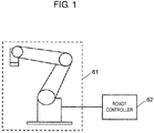
- FIG. 1 is a schematic view that illustrates a configuration of a 6-axis vertical articulated robot according to the exemplary embodiment.
- the 6-axis vertical articulated robot includes robotic mechanism 61 and robot controller 62.
- Robotic mechanism 61 includes a plurality of arms and joint axes (not shown), and uses reduction gears disposed near the joint axes, respectively, to drive the arms.
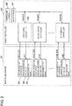
- FIG. 2 is a block diagram that illustrates an interior configuration of robotic mechanism 61 and robot controller 62.
- robot controller 62 a configuration related to control of position of the 6-axis vertical articulated robot will be especially described.
- robot controller 62 contains controls and display 63, main controller 64, and first servo controller 65, and second to sixth servo controllers.
- Controls and display 63 receives instructions on motion of the arms and the like of robotic mechanism 61.
- Main controller 64 stores trajectories of motion of the arms and the like of robotic mechanism 61.
- the controls and display 63 outputs position commands ⁇ com1 to ⁇ com6 on positions of the axes (six axes, for example) of the robot to the axes of the robot, based on trajectories of motion that correspond to the received instructions.
- first servo controller 65 and the second to sixth servo controllers of the axes of the robot control first motor 66 and second to sixth motors within robotic mechanism 61, respectively.
- Reduction gears 53 are provided for each of the motors.
- a conventional servo controller will be described before servo controller 65 according to the present exemplary embodiment is described.
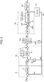
- FIG. 3 is a block diagram that illustrates a configuration of the conventional servo controller.
- Position control block 6 generates velocity loop command ⁇ com by multiplying a difference between position command ⁇ com and motor position feedback ⁇ m by position proportional gain 5.
- Position control block 6 receives motor position feedback ⁇ m from encoder 51 that is a position sensor attached to a motor.
- Velocity control block 10 multiplies a difference between velocity loop command ⁇ com and motor velocity feedback ⁇ m by velocity proportional gain 8. Velocity control block 10 determines motor velocity feetback ⁇ m by differentiating motor position feedback ⁇ m with respect to derivative element 32. Velocity control block 10 multiplies an integral of the difference by velocity integral gain 9. Velocity control block 10 generates motor torque electric current command Iq by adding the multiplied integral to the difference multiplied by velocity proportional gain 8.
- Field weakening control may be necessary to rotate the motor at high velocity.
- the field weakening control weakens counter-electromotive force in the motor that increases in proportion to rotation of the motor. That is, a difference between the counter-electromotive force in the motor and voltage of a power source is maintained. Therefore, electric current flows through the motor, and thus the motor is rotated.
- the field weakening control is generally performed by vector addition of motor torque electric current command Iq and field weakening electric current command Id0 for a motor reactive electric current component.
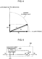
- FIG. 4 expresses Equation (1) as a vector diagram.
- FIG. 5 is a block diagram that illustrates d-axis-electric-current adding zeroth-block 100 in detail.
- ⁇ m may be zero and Iq may be zero, and thus Id0 may be zero and Im may be zero at an axis to which gravity is not applied. In that case, electric current does not flow through the motor, and the motor does not generate heat. If grease for reduction gears hardens at low temperature, the grease for reduction gears is not heated.
- value Id1 of addition of d-axis electric current is determined based on a temperature sensor and motor torque electric current command Iq. Consequently, reactive electric current component flows through a motor and the motor generates heat even when the motor is stopped. Consequently, grease for reduction gears is heated, and viscous friction of the grease for reduction gears is decreased.
- FIG. 6 is a block diagram that illustrates a configuration of a conventional servo controller. Differences between FIG. 6 and FIG. 3 are that encoder 52 incorporates a temperature sensor, and outputs value Tc of the temperature sensor, and d-axis-electric-current adding first-block 150 is provided instead of d-axis-electric-current adding zeroth-block 100.
- FIG. 7 is a block diagram that illustrates d-axis-electric-current adding first-block 150 in detail.
- FIG. 8 is a flowchart that illustrates operation of d-axis-electric-current adding first-block 150.
- step 8-1 in FIG. 8 field weakening electric current command Id0 is calculated. Step 8-1 is performed in field weakening block 102 in FIG. 7 .
- step 8-2 it is determined whether value Tc of the temperature sensor is less than threshold Tcth of the temperature sensor. If value Tc of the temperature sensor is less than threshold Tcth of the temperature sensor, step 8-3 is performed. If value Tc of the temperature sensor is not less than threshold Tcth of the temperature sensor, step 8-5 is performed.
- step 8-3 it is determined whether an absolute value of motor torque electric current command Iq is less than motor torque electric current threshold Iqth. If the absolute value of motor torque electric current command Iq is less than motor torque electric current threshold Iqth, step 8-4 is performed. If the absolute value of motor torque electric current command Iq is not less than motor torque electric current threshold Iqth, step 8-5 is performed.
- step 8-4 value Id_add assigned to a value of addition of d-axis electric current is assigned to value Id1 of addition of d-axis electric current.
- step 8-5 "zero" is assigned to value Id1 of addition of axis electric current.
- Steps 8-2 to 8-5 are performed in d-axis-addition determining first-block 104 in FIG. 7 .
- the heated motor heats grease for reduction gears that hardens at low temperature. Consequently, viscous friction of the grease for reduction gears is decreased.
- the method may allow motor command electric current Im to exceed a maximum allowable value or may cause wrong overload.
- a motor has a maximum allowable value for electric current that flows through the motor. If an absolute value of electric current through the motor exceeds the maximum allowable value, winding of the motor may be damaged, or a magnet of the motor may be demagnetized.
- absolute value Ia of motor command electric current Im Before value Id1 of addition of d-axis electric current is added, absolute value Ia of motor command electric current Im may have reached the maximum allowable value. Even if an absolute value of motor torque electric current command Iq is less than motor torque electric current threshold Iqth, absolute value Ia of motor command electric current Im may reach a maximum allowable value for Im after field weakening electric current command Id0 is added.
- the overload detecting function detects overload. Consequently, an integral of absolute value Ia of motor command electric current Im over time does not exceed a limit.
- the limit is a limit on rise in temperature of winding of a motor.
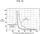
- FIG. 12 illustrates a motor-time-limit-characteristic curve.
- a vertical axis of the motor-time-limit-characteristic curve represents a period of time during which motor electric current is output.
- a horizontal axis of the motor-time-limit-characteristic curve represents a value of motor electric current (maximum ratio).
- a broken line in FIG. 12 represents limit characteristic.
- the limit characteristic represents a time when temperature of winding of the motor rises to a limit, and a value of motor electric current at that time. That is, if a value of motor electric current is 40%, a time when temperature of a motor rises to a limit is a time when a period of time during which motor electric current is output reaches about 100 seconds.
- a time when temperature of a motor rises to a limit is a time when a period of time during which motor electric current is output reaches about 25 seconds. If a value of motor electric current is 70%, a time when a temperature of a motor rises to a limit is a time when a period of time during which motor electric current is output reaches about 8 seconds.
- the overload detecting function detects overload. Consequently, an integral of absolute value Ia of motor command electric current Im over time is less than or equal to the limit.
- FIG. 11 is a flowchart of detection of overload. The process is performed at regular intervals ⁇ T.
- ⁇ T is an interval at which detection of overload is performed.
- OLdet(n - 1) is a value (OLdet) of detected overload that has been detected one interval before.
- value OLdet of detected overload is compared with first threshold OLth of overload. If a condition of Inequality (6) is satisfied, overload is determined.
- step 11-2 overload is determined, and the motor is stopped in step 11-3. Further, in step 11-4, notice of malfunction is displayed, and a process of detecting overload is finished.
- the display of notice of malfunction is display of a message "overload is detected" on controls and display 63 in FIG. 2 to notify a user of malfunction.
- step 11-2 If determination is "N" in step 11-2, no overload is determined, and the process of detecting overload is finished.
- a solid line represents overload detection threshold characteristic.
- the overload detection threshold characteristic (solid line) is formed below the limit characteristic (broken line). This indicates that a method of calculating value OLdet of detected overload in Equation (5) is appropriate.
- Block 18 that illustrates a motor and external force in FIG. 6 is expressed as numerical expressions in Equations (7) and (8) described later.
- Supposing reduction gears 53 are rigid bodies, torque ⁇ m generated by the motor, on a side driven by the motor, is expressed by Equation (7), and torque ⁇ m generated by the motor, on a load side, is expressed by Equation (8).
- Iq is used instead of Im in Equation (7) because Iq is an active component for generation of torque. Since it is supposed that reduction gears 53 are rigid bodies, output position ⁇ L from which reduction gears output is a value calculated by only multiplying motor position feedback ⁇ m by gear ratio (coefficient of proportionality). Therefore, derivative ⁇ m that is a derivative of position feedback ⁇ m of the motor is used instead of output position ⁇ L from which the reduction gears output in Equation (8).
- value Id1 of addition of d-axis electric current is added to deal with the low temperature, absolute value Ia of motor command electric current Im increases further, and thus value OLdet of detected overload also increases further. If the condition of Inequality (6) is satisfied by the increase in value OLdet of detected overload, wrong overload detection occurs, and the control equipment stops.
- first servo controller 65 will be described to decrease viscous friction of grease for reduction gears at low temperature without demagnetizing a magnet of a motor and causing wrong overload detection.
- FIG. 13 is a block diagram that illustrates a configuration of first servo controller 65 according to the present exemplary embodiment. Differences between FIG. 13 and FIG. 6 are that overload detecting block 204 is added, and d-axis-electric-current adding second-block 200 is provided instead of d-axis-electric-current adding first-block 150.
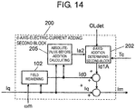
- FIG. 14 is a block diagram that illustrates d-axis-electric-current adding second-block 200 in detail. A difference between FIG. 14 and FIG. 7 is that absolute-value-before-addition calculating block 205 is provided.
- FIG. 15 is a flowchart that illustrates operation in FIG. 14 , that is, a robot control method according to the present exemplary embodiment
- step 15-1 field weakening electric current command Id0 is calculated in field weakening block 102 in FIG. 14 .
- step 15-2 absolute value Ia2 of motor command electric current Im before addition of d-axis electric current is determined (Equation (10)) in absolute-value-before-addition calculating block 205 in FIG. 14 .
- Ia 2 ⁇ Iq 2 + Id 0 2
- step 15-3 value Tc of the temperature sensor is compared with threshold Tcth of the temperature sensor. If value Tc of the temperature sensor is less than threshold Tcth of the temperature sensor, step 15-4 is performed. If value Tc of the temperature sensor is not less than threshold Tcth of the temperature sensor, step 15-7 is performed.
- step 15-4 Ia2 calculated in step 15-2 is compared with threshold Iath2 of an absolute value of electric current. If Ia2 is less than Iath2, step 15-5 is performed. If Ia2 is not less than Iath2, step 15-7 is performed.
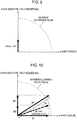
- FIG. 16 illustrates electric current vectors.
- absolute value Ia2 of motor command electric current Im before addition of d-axis electric current is less than threshold Iath2 of an absolute value of electric current.
- step 15-4 it is ascertained that, even if value IdlA of addition of d-axis electric current that will be describe later is added to motor command electric current Im before addition of d-axis electric current, absolute value Ia of motor command electric current Im does not exceed a maximum allowable value.
- step 15-5 value OLdet of detected overload is compared with second threshold OLth2 of overload. Value OLdet of detected overload is calculated in overload detecting block 204 in FIG. 13 . If value OLdet of detected overload is less than second threshold OLth2 of overload, step 15-6 is performed. If value OLdet of detected overload is not less than second threshold OLth2 of overload, step 15-7 is performed. Second threshold OLth2 of overload is lower than first threshold OLth of overload.
- step 15-6 value Id_addA assigned to a value of addition of d-axis electric current is assigned to value IdlA of addition of d-axis electric current.
- step 15-7 "zero" is assigned to value IdlA of addition of d-axis electric current.
- Steps 15-3 to 15-7 are performed in d-axis-addition determining second-block 202 in FIG. 14 .
- FIG. 17 illustrates motor command electric current Im calculated using Equation (11). Although IdlA is added to FIG. 16 in FIG. 17 , absolute value Ia of motor command electric current Im does not exceed the maximum allowable value.
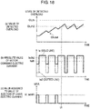
- FIG. 18(a) represents a value of detected overload.
- FIG. 18(b) represents an absolute value of motor command electric current.
- FIG. 18(c) represents a value assigned to a value of addition of d-axis electric current.
- a condition (OLdet ⁇ OLth2) in step 15-5 is satisfied until time t1.
- step 15-4 While a condition (Ia2 ⁇ Iath2) in step 15-4 is satisfied until time tl, processes in steps 15-6 and 15-8 are performed, and thus d-axis electric current is added. Therefore, increase in value OLdet of detected overload calculated in Equation (5) is highly probable, and thus value OLdet of detected overload tends to increase generally until time t1.
- a robot control method controls motion of a robot arm by using servo motors connected to reduction gears, and includes: determining whether temperature is less than or equal to a predetermined value; determining whether an absolute value of a motor electric current command is less than or equal to a predetermined value; determining whether a level of detected overload is less than or equal to a predetermined value; and adding d-axis electric current.
- the second to fifth servo controllers of robot controller 62 in FIG. 2 each have similar configurations as first servo controller 65 described with reference to FIGS. 13 to 17 and FIGS. 18(a) to 18(c) . Therefore, the second to fifth servo controllers will not be described.
- a robot control method makes a motor generate heat to decrease viscous friction of grease for reduction gears at low temperature without demagnetizing a magnet of the motor and causing wrong overload. Therefore, the robot control method according to the present disclosure is usefully applied to industrial robots, such as welding robots.
Landscapes
- Engineering & Computer Science (AREA)
- Power Engineering (AREA)
- Robotics (AREA)
- Mechanical Engineering (AREA)
- Control Of Ac Motors In General (AREA)
- Manipulator (AREA)
- Control Of Electric Motors In General (AREA)
- Protection Of Generators And Motors (AREA)
- Numerical Control (AREA)
Applications Claiming Priority (2)
| Application Number | Priority Date | Filing Date | Title |
|---|---|---|---|
| JP2017038341 | 2017-03-01 | ||
| PCT/JP2018/005643 WO2018159341A1 (fr) | 2017-03-01 | 2018-02-19 | Procédé de commande de robot |
Publications (3)
| Publication Number | Publication Date |
|---|---|
| EP3576298A1 true EP3576298A1 (fr) | 2019-12-04 |
| EP3576298A4 EP3576298A4 (fr) | 2020-01-08 |
| EP3576298B1 EP3576298B1 (fr) | 2020-12-16 |
Family
ID=63370892
Family Applications (1)
| Application Number | Title | Priority Date | Filing Date |
|---|---|---|---|
| EP18760661.1A Active EP3576298B1 (fr) | 2017-03-01 | 2018-02-19 | Procédé de commande de robot |
Country Status (5)
| Country | Link |
|---|---|
| US (1) | US11298819B2 (fr) |
| EP (1) | EP3576298B1 (fr) |
| JP (1) | JP6975886B2 (fr) |
| CN (1) | CN110366818B (fr) |
| WO (1) | WO2018159341A1 (fr) |
Families Citing this family (8)
| Publication number | Priority date | Publication date | Assignee | Title |
|---|---|---|---|---|
| DE102019104984A1 (de) * | 2019-02-27 | 2020-08-27 | Mahle International Gmbh | Verfahren zum Betreiben eines dreiphasigen elektrischen Motors und dreiphasiger elektrischer Motor |
| CN109768748A (zh) * | 2019-03-29 | 2019-05-17 | 广东美的制冷设备有限公司 | 矢量控制系统、控制方法、装置、空调器与存储介质 |
| JP2021078207A (ja) * | 2019-11-07 | 2021-05-20 | ファナック株式会社 | 産業用機械の制御システム |
| US11691282B2 (en) * | 2020-03-26 | 2023-07-04 | Mitsubishi Electric Corporation | Friction compensation device, and robot control device |
| CN112476423B (zh) * | 2020-11-12 | 2022-03-08 | 腾讯科技(深圳)有限公司 | 机器人的关节电机控制方法、装置、设备及存储介质 |
| US20230271319A1 (en) * | 2022-02-28 | 2023-08-31 | Denso Wave Incorporated | Method of generating a learning model for transferring fluid from one container to another by controlling robot arm based on a machine-learned learning model, and a method and system for weighing the fluid |
| CN116690556B (zh) * | 2023-05-04 | 2025-12-19 | 北京现代汽车有限公司 | 控制设备、设备控制方法及系统 |
| US20250121497A1 (en) * | 2023-10-16 | 2025-04-17 | Toyota Motor Engineering & Manufacturing North America, Inc. | Systems and methods for electric current-based robot command alteration |
Family Cites Families (12)
| Publication number | Priority date | Publication date | Assignee | Title |
|---|---|---|---|---|
| JPS63127885A (ja) * | 1986-11-18 | 1988-05-31 | 横河電機株式会社 | ロボツトア−ムの温度制御装置 |
| JPH0637903Y2 (ja) * | 1987-02-12 | 1994-10-05 | 坂本文具株式会社 | ホツチキス |
| JP3625901B2 (ja) * | 1995-06-30 | 2005-03-02 | 三菱電機株式会社 | サーボ制御システムの自動適正化方法および装置 |
| JPH10180662A (ja) * | 1996-12-27 | 1998-07-07 | Tokico Ltd | 工業用ロボット |
| JP4292871B2 (ja) | 2003-05-29 | 2009-07-08 | 株式会社ジェイテクト | 車両の操舵制御装置 |
| JP4211571B2 (ja) * | 2003-11-04 | 2009-01-21 | トヨタ自動車株式会社 | 操舵装置 |
| JP2005219133A (ja) | 2004-02-03 | 2005-08-18 | Fanuc Ltd | ロボット用サーボモータ制御装置およびロボット |
| JP5468215B2 (ja) * | 2008-06-09 | 2014-04-09 | ダイキン工業株式会社 | 空気調和機及び空気調和機の製造方法 |
| JP6079786B2 (ja) * | 2012-11-20 | 2017-02-15 | 株式会社安川電機 | モータ駆動システムおよびモータ制御装置 |
| JP6541301B2 (ja) * | 2014-03-28 | 2019-07-10 | キヤノン株式会社 | ロボット装置、ロボット装置の制御方法、ロボット制御プログラム、及び記録媒体 |
| JP2016030403A (ja) | 2014-07-29 | 2016-03-07 | 東芝機械株式会社 | 電動機の制御方法、電動機の制御装置及び成形装置 |
| WO2016178262A1 (fr) * | 2015-05-01 | 2016-11-10 | 三菱電機株式会社 | Dispositif de commande de direction assistée électrique et procédé de commande de direction assistée électrique |
-
2018
- 2018-02-19 EP EP18760661.1A patent/EP3576298B1/fr active Active
- 2018-02-19 JP JP2019502882A patent/JP6975886B2/ja active Active
- 2018-02-19 WO PCT/JP2018/005643 patent/WO2018159341A1/fr not_active Ceased
- 2018-02-19 CN CN201880014523.8A patent/CN110366818B/zh active Active
-
2019
- 2019-08-22 US US16/548,295 patent/US11298819B2/en active Active
Also Published As
| Publication number | Publication date |
|---|---|
| JP6975886B2 (ja) | 2021-12-01 |
| WO2018159341A1 (fr) | 2018-09-07 |
| CN110366818A (zh) | 2019-10-22 |
| EP3576298B1 (fr) | 2020-12-16 |
| JPWO2018159341A1 (ja) | 2019-12-19 |
| US20190375098A1 (en) | 2019-12-12 |
| US11298819B2 (en) | 2022-04-12 |
| CN110366818B (zh) | 2023-05-12 |
| EP3576298A4 (fr) | 2020-01-08 |
Similar Documents
| Publication | Publication Date | Title |
|---|---|---|
| EP3576298B1 (fr) | Procédé de commande de robot | |
| JP4294646B2 (ja) | ロボットアームの制御方法および制御装置 | |
| US10690558B2 (en) | Robot collision detection method | |
| US9827681B2 (en) | Human cooperation robot system in which robot is caused to perform retreat operation depending on external force | |
| EP3150341B1 (fr) | Dispositif de commande de robot | |
| JP5383911B2 (ja) | ロボット制御装置 | |
| JP5927440B2 (ja) | ロボットの異常表示方法 | |
| EP1864886A2 (fr) | Appareil de direction assistée électrique | |
| JP2013169609A (ja) | ロボットの衝突検出方法 | |
| EP3439168B1 (fr) | Dispositif de commande de moteur | |
| JP3933158B2 (ja) | ロボットの衝突検出方法 | |
| CN103069713B (zh) | 电机控制装置 | |
| CN116209548A (zh) | 电流限制装置、机器人系统以及电流限制方法 | |
| JP4228965B2 (ja) | ロボットの制御方法 | |
| CN109698654B (zh) | 一种控制自动离合器执行电机的方法和装置 | |
| JP2010136583A (ja) | 電動機のトルク制御装置 | |
| US12145275B2 (en) | Robot control method and robot control device | |
| JP2013006230A (ja) | 回転動力源制御方法および回転動力源制御装置、並びにロボット | |
| WO2011004587A1 (fr) | Procédé et dispositif de commande de position |
Legal Events
| Date | Code | Title | Description |
|---|---|---|---|
| STAA | Information on the status of an ep patent application or granted ep patent |
Free format text: STATUS: THE INTERNATIONAL PUBLICATION HAS BEEN MADE |
|
| PUAI | Public reference made under article 153(3) epc to a published international application that has entered the european phase |
Free format text: ORIGINAL CODE: 0009012 |
|
| STAA | Information on the status of an ep patent application or granted ep patent |
Free format text: STATUS: REQUEST FOR EXAMINATION WAS MADE |
|
| 17P | Request for examination filed |
Effective date: 20190828 |
|
| AK | Designated contracting states |
Kind code of ref document: A1 Designated state(s): AL AT BE BG CH CY CZ DE DK EE ES FI FR GB GR HR HU IE IS IT LI LT LU LV MC MK MT NL NO PL PT RO RS SE SI SK SM TR |
|
| AX | Request for extension of the european patent |
Extension state: BA ME |
|
| A4 | Supplementary search report drawn up and despatched |
Effective date: 20191210 |
|
| RIC1 | Information provided on ipc code assigned before grant |
Ipc: B25J 13/00 20060101ALI20191204BHEP Ipc: B25J 9/16 20060101ALI20191204BHEP Ipc: H02P 29/64 20160101AFI20191204BHEP Ipc: H02P 21/22 20160101ALI20191204BHEP Ipc: H02P 29/62 20160101ALI20191204BHEP Ipc: H02P 21/00 20160101ALI20191204BHEP |
|
| DAV | Request for validation of the european patent (deleted) | ||
| DAX | Request for extension of the european patent (deleted) | ||
| REG | Reference to a national code |
Ref country code: DE Ref legal event code: R079 Ref document number: 602018010916 Country of ref document: DE Free format text: PREVIOUS MAIN CLASS: H02P0029640000 Ipc: H02P0029620000 |
|
| GRAP | Despatch of communication of intention to grant a patent |
Free format text: ORIGINAL CODE: EPIDOSNIGR1 |
|
| STAA | Information on the status of an ep patent application or granted ep patent |
Free format text: STATUS: GRANT OF PATENT IS INTENDED |
|
| RIC1 | Information provided on ipc code assigned before grant |
Ipc: H02P 21/22 20160101ALI20200813BHEP Ipc: H02P 21/00 20160101ALI20200813BHEP Ipc: B25J 9/16 20060101ALI20200813BHEP Ipc: H02P 29/64 20160101ALI20200813BHEP Ipc: H02P 29/62 20160101AFI20200813BHEP |
|
| INTG | Intention to grant announced |
Effective date: 20200916 |
|
| GRAS | Grant fee paid |
Free format text: ORIGINAL CODE: EPIDOSNIGR3 |
|
| GRAA | (expected) grant |
Free format text: ORIGINAL CODE: 0009210 |
|
| STAA | Information on the status of an ep patent application or granted ep patent |
Free format text: STATUS: THE PATENT HAS BEEN GRANTED |
|
| AK | Designated contracting states |
Kind code of ref document: B1 Designated state(s): AL AT BE BG CH CY CZ DE DK EE ES FI FR GB GR HR HU IE IS IT LI LT LU LV MC MK MT NL NO PL PT RO RS SE SI SK SM TR |
|
| REG | Reference to a national code |
Ref country code: GB Ref legal event code: FG4D |
|
| REG | Reference to a national code |
Ref country code: IE Ref legal event code: FG4D |
|
| REG | Reference to a national code |
Ref country code: DE Ref legal event code: R096 Ref document number: 602018010916 Country of ref document: DE |
|
| REG | Reference to a national code |
Ref country code: AT Ref legal event code: REF Ref document number: 1346517 Country of ref document: AT Kind code of ref document: T Effective date: 20210115 |
|
| REG | Reference to a national code |
Ref country code: NL Ref legal event code: FP |
|
| PG25 | Lapsed in a contracting state [announced via postgrant information from national office to epo] |
Ref country code: RS Free format text: LAPSE BECAUSE OF FAILURE TO SUBMIT A TRANSLATION OF THE DESCRIPTION OR TO PAY THE FEE WITHIN THE PRESCRIBED TIME-LIMIT Effective date: 20201216 Ref country code: FI Free format text: LAPSE BECAUSE OF FAILURE TO SUBMIT A TRANSLATION OF THE DESCRIPTION OR TO PAY THE FEE WITHIN THE PRESCRIBED TIME-LIMIT Effective date: 20201216 Ref country code: NO Free format text: LAPSE BECAUSE OF FAILURE TO SUBMIT A TRANSLATION OF THE DESCRIPTION OR TO PAY THE FEE WITHIN THE PRESCRIBED TIME-LIMIT Effective date: 20210316 Ref country code: GR Free format text: LAPSE BECAUSE OF FAILURE TO SUBMIT A TRANSLATION OF THE DESCRIPTION OR TO PAY THE FEE WITHIN THE PRESCRIBED TIME-LIMIT Effective date: 20210317 |
|
| REG | Reference to a national code |
Ref country code: AT Ref legal event code: MK05 Ref document number: 1346517 Country of ref document: AT Kind code of ref document: T Effective date: 20201216 |
|
| PG25 | Lapsed in a contracting state [announced via postgrant information from national office to epo] |
Ref country code: LV Free format text: LAPSE BECAUSE OF FAILURE TO SUBMIT A TRANSLATION OF THE DESCRIPTION OR TO PAY THE FEE WITHIN THE PRESCRIBED TIME-LIMIT Effective date: 20201216 Ref country code: SE Free format text: LAPSE BECAUSE OF FAILURE TO SUBMIT A TRANSLATION OF THE DESCRIPTION OR TO PAY THE FEE WITHIN THE PRESCRIBED TIME-LIMIT Effective date: 20201216 Ref country code: BG Free format text: LAPSE BECAUSE OF FAILURE TO SUBMIT A TRANSLATION OF THE DESCRIPTION OR TO PAY THE FEE WITHIN THE PRESCRIBED TIME-LIMIT Effective date: 20210316 |
|
| PG25 | Lapsed in a contracting state [announced via postgrant information from national office to epo] |
Ref country code: HR Free format text: LAPSE BECAUSE OF FAILURE TO SUBMIT A TRANSLATION OF THE DESCRIPTION OR TO PAY THE FEE WITHIN THE PRESCRIBED TIME-LIMIT Effective date: 20201216 |
|
| REG | Reference to a national code |
Ref country code: LT Ref legal event code: MG9D |
|
| PG25 | Lapsed in a contracting state [announced via postgrant information from national office to epo] |
Ref country code: CZ Free format text: LAPSE BECAUSE OF FAILURE TO SUBMIT A TRANSLATION OF THE DESCRIPTION OR TO PAY THE FEE WITHIN THE PRESCRIBED TIME-LIMIT Effective date: 20201216 Ref country code: EE Free format text: LAPSE BECAUSE OF FAILURE TO SUBMIT A TRANSLATION OF THE DESCRIPTION OR TO PAY THE FEE WITHIN THE PRESCRIBED TIME-LIMIT Effective date: 20201216 Ref country code: SM Free format text: LAPSE BECAUSE OF FAILURE TO SUBMIT A TRANSLATION OF THE DESCRIPTION OR TO PAY THE FEE WITHIN THE PRESCRIBED TIME-LIMIT Effective date: 20201216 Ref country code: SK Free format text: LAPSE BECAUSE OF FAILURE TO SUBMIT A TRANSLATION OF THE DESCRIPTION OR TO PAY THE FEE WITHIN THE PRESCRIBED TIME-LIMIT Effective date: 20201216 Ref country code: PT Free format text: LAPSE BECAUSE OF FAILURE TO SUBMIT A TRANSLATION OF THE DESCRIPTION OR TO PAY THE FEE WITHIN THE PRESCRIBED TIME-LIMIT Effective date: 20210416 Ref country code: RO Free format text: LAPSE BECAUSE OF FAILURE TO SUBMIT A TRANSLATION OF THE DESCRIPTION OR TO PAY THE FEE WITHIN THE PRESCRIBED TIME-LIMIT Effective date: 20201216 Ref country code: LT Free format text: LAPSE BECAUSE OF FAILURE TO SUBMIT A TRANSLATION OF THE DESCRIPTION OR TO PAY THE FEE WITHIN THE PRESCRIBED TIME-LIMIT Effective date: 20201216 |
|
| PG25 | Lapsed in a contracting state [announced via postgrant information from national office to epo] |
Ref country code: AT Free format text: LAPSE BECAUSE OF FAILURE TO SUBMIT A TRANSLATION OF THE DESCRIPTION OR TO PAY THE FEE WITHIN THE PRESCRIBED TIME-LIMIT Effective date: 20201216 Ref country code: PL Free format text: LAPSE BECAUSE OF FAILURE TO SUBMIT A TRANSLATION OF THE DESCRIPTION OR TO PAY THE FEE WITHIN THE PRESCRIBED TIME-LIMIT Effective date: 20201216 |
|
| REG | Reference to a national code |
Ref country code: DE Ref legal event code: R097 Ref document number: 602018010916 Country of ref document: DE |
|
| PG25 | Lapsed in a contracting state [announced via postgrant information from national office to epo] |
Ref country code: IS Free format text: LAPSE BECAUSE OF FAILURE TO SUBMIT A TRANSLATION OF THE DESCRIPTION OR TO PAY THE FEE WITHIN THE PRESCRIBED TIME-LIMIT Effective date: 20210416 Ref country code: MC Free format text: LAPSE BECAUSE OF FAILURE TO SUBMIT A TRANSLATION OF THE DESCRIPTION OR TO PAY THE FEE WITHIN THE PRESCRIBED TIME-LIMIT Effective date: 20201216 |
|
| PLBE | No opposition filed within time limit |
Free format text: ORIGINAL CODE: 0009261 |
|
| STAA | Information on the status of an ep patent application or granted ep patent |
Free format text: STATUS: NO OPPOSITION FILED WITHIN TIME LIMIT |
|
| REG | Reference to a national code |
Ref country code: BE Ref legal event code: MM Effective date: 20210228 |
|
| PG25 | Lapsed in a contracting state [announced via postgrant information from national office to epo] |
Ref country code: CH Free format text: LAPSE BECAUSE OF NON-PAYMENT OF DUE FEES Effective date: 20210228 Ref country code: AL Free format text: LAPSE BECAUSE OF FAILURE TO SUBMIT A TRANSLATION OF THE DESCRIPTION OR TO PAY THE FEE WITHIN THE PRESCRIBED TIME-LIMIT Effective date: 20201216 Ref country code: LU Free format text: LAPSE BECAUSE OF NON-PAYMENT OF DUE FEES Effective date: 20210219 Ref country code: LI Free format text: LAPSE BECAUSE OF NON-PAYMENT OF DUE FEES Effective date: 20210228 Ref country code: IT Free format text: LAPSE BECAUSE OF FAILURE TO SUBMIT A TRANSLATION OF THE DESCRIPTION OR TO PAY THE FEE WITHIN THE PRESCRIBED TIME-LIMIT Effective date: 20201216 |
|
| 26N | No opposition filed |
Effective date: 20210917 |
|
| PG25 | Lapsed in a contracting state [announced via postgrant information from national office to epo] |
Ref country code: DK Free format text: LAPSE BECAUSE OF FAILURE TO SUBMIT A TRANSLATION OF THE DESCRIPTION OR TO PAY THE FEE WITHIN THE PRESCRIBED TIME-LIMIT Effective date: 20201216 |
|
| PG25 | Lapsed in a contracting state [announced via postgrant information from national office to epo] |
Ref country code: IE Free format text: LAPSE BECAUSE OF NON-PAYMENT OF DUE FEES Effective date: 20210219 Ref country code: ES Free format text: LAPSE BECAUSE OF FAILURE TO SUBMIT A TRANSLATION OF THE DESCRIPTION OR TO PAY THE FEE WITHIN THE PRESCRIBED TIME-LIMIT Effective date: 20201216 Ref country code: FR Free format text: LAPSE BECAUSE OF NON-PAYMENT OF DUE FEES Effective date: 20210228 |
|
| PG25 | Lapsed in a contracting state [announced via postgrant information from national office to epo] |
Ref country code: SI Free format text: LAPSE BECAUSE OF FAILURE TO SUBMIT A TRANSLATION OF THE DESCRIPTION OR TO PAY THE FEE WITHIN THE PRESCRIBED TIME-LIMIT Effective date: 20201216 |
|
| PG25 | Lapsed in a contracting state [announced via postgrant information from national office to epo] |
Ref country code: IS Free format text: LAPSE BECAUSE OF FAILURE TO SUBMIT A TRANSLATION OF THE DESCRIPTION OR TO PAY THE FEE WITHIN THE PRESCRIBED TIME-LIMIT Effective date: 20210416 |
|
| PG25 | Lapsed in a contracting state [announced via postgrant information from national office to epo] |
Ref country code: BE Free format text: LAPSE BECAUSE OF NON-PAYMENT OF DUE FEES Effective date: 20210228 |
|
| GBPC | Gb: european patent ceased through non-payment of renewal fee |
Effective date: 20220219 |
|
| PG25 | Lapsed in a contracting state [announced via postgrant information from national office to epo] |
Ref country code: GB Free format text: LAPSE BECAUSE OF NON-PAYMENT OF DUE FEES Effective date: 20220219 |
|
| PG25 | Lapsed in a contracting state [announced via postgrant information from national office to epo] |
Ref country code: CY Free format text: LAPSE BECAUSE OF FAILURE TO SUBMIT A TRANSLATION OF THE DESCRIPTION OR TO PAY THE FEE WITHIN THE PRESCRIBED TIME-LIMIT Effective date: 20201216 |
|
| PG25 | Lapsed in a contracting state [announced via postgrant information from national office to epo] |
Ref country code: HU Free format text: LAPSE BECAUSE OF FAILURE TO SUBMIT A TRANSLATION OF THE DESCRIPTION OR TO PAY THE FEE WITHIN THE PRESCRIBED TIME-LIMIT; INVALID AB INITIO Effective date: 20180219 |
|
| PG25 | Lapsed in a contracting state [announced via postgrant information from national office to epo] |
Ref country code: MK Free format text: LAPSE BECAUSE OF FAILURE TO SUBMIT A TRANSLATION OF THE DESCRIPTION OR TO PAY THE FEE WITHIN THE PRESCRIBED TIME-LIMIT Effective date: 20201216 |
|
| PG25 | Lapsed in a contracting state [announced via postgrant information from national office to epo] |
Ref country code: TR Free format text: LAPSE BECAUSE OF FAILURE TO SUBMIT A TRANSLATION OF THE DESCRIPTION OR TO PAY THE FEE WITHIN THE PRESCRIBED TIME-LIMIT Effective date: 20201216 |
|
| PG25 | Lapsed in a contracting state [announced via postgrant information from national office to epo] |
Ref country code: MT Free format text: LAPSE BECAUSE OF FAILURE TO SUBMIT A TRANSLATION OF THE DESCRIPTION OR TO PAY THE FEE WITHIN THE PRESCRIBED TIME-LIMIT Effective date: 20201216 |
|
| PGFP | Annual fee paid to national office [announced via postgrant information from national office to epo] |
Ref country code: NL Payment date: 20260218 Year of fee payment: 9 |
|
| PGFP | Annual fee paid to national office [announced via postgrant information from national office to epo] |
Ref country code: DE Payment date: 20260218 Year of fee payment: 9 |