EP3576307A1 - Dispositif de sonde, dispositif d'analyse, système et procédé pour tester un équipement de transmission d'énergie sans fil - Google Patents
Dispositif de sonde, dispositif d'analyse, système et procédé pour tester un équipement de transmission d'énergie sans fil Download PDFInfo
- Publication number
- EP3576307A1 EP3576307A1 EP18204141.8A EP18204141A EP3576307A1 EP 3576307 A1 EP3576307 A1 EP 3576307A1 EP 18204141 A EP18204141 A EP 18204141A EP 3576307 A1 EP3576307 A1 EP 3576307A1
- Authority
- EP
- European Patent Office
- Prior art keywords
- wireless power
- power transmitter
- analyzer
- probe
- receiver
- Prior art date
- Legal status (The legal status is an assumption and is not a legal conclusion. Google has not performed a legal analysis and makes no representation as to the accuracy of the status listed.)
- Granted
Links
Images




Classifications
-
- H—ELECTRICITY
- H04—ELECTRIC COMMUNICATION TECHNIQUE
- H04B—TRANSMISSION
- H04B5/00—Near-field transmission systems, e.g. inductive or capacitive transmission systems
- H04B5/70—Near-field transmission systems, e.g. inductive or capacitive transmission systems specially adapted for specific purposes
- H04B5/79—Near-field transmission systems, e.g. inductive or capacitive transmission systems specially adapted for specific purposes for data transfer in combination with power transfer
-
- H—ELECTRICITY
- H04—ELECTRIC COMMUNICATION TECHNIQUE
- H04B—TRANSMISSION
- H04B5/00—Near-field transmission systems, e.g. inductive or capacitive transmission systems
- H04B5/70—Near-field transmission systems, e.g. inductive or capacitive transmission systems specially adapted for specific purposes
- H04B5/73—Near-field transmission systems, e.g. inductive or capacitive transmission systems specially adapted for specific purposes for taking measurements, e.g. using sensing coils
-
- G—PHYSICS
- G01—MEASURING; TESTING
- G01R—MEASURING ELECTRIC VARIABLES; MEASURING MAGNETIC VARIABLES
- G01R1/00—Details of instruments or arrangements of the types included in groups G01R5/00 - G01R13/00 and G01R31/00
- G01R1/02—General constructional details
- G01R1/06—Measuring leads; Measuring probes
- G01R1/067—Measuring probes
-
- G—PHYSICS
- G01—MEASURING; TESTING
- G01R—MEASURING ELECTRIC VARIABLES; MEASURING MAGNETIC VARIABLES
- G01R1/00—Details of instruments or arrangements of the types included in groups G01R5/00 - G01R13/00 and G01R31/00
- G01R1/02—General constructional details
- G01R1/06—Measuring leads; Measuring probes
- G01R1/067—Measuring probes
- G01R1/07—Non contact-making probes
-
- G—PHYSICS
- G01—MEASURING; TESTING
- G01R—MEASURING ELECTRIC VARIABLES; MEASURING MAGNETIC VARIABLES
- G01R15/00—Details of measuring arrangements of the types provided for in groups G01R17/00 - G01R29/00, G01R33/00 - G01R33/26 or G01R35/00
- G01R15/14—Adaptations providing voltage or current isolation, e.g. for high-voltage or high-current networks
- G01R15/18—Adaptations providing voltage or current isolation, e.g. for high-voltage or high-current networks using inductive devices, e.g. transformers
-
- G—PHYSICS
- G01—MEASURING; TESTING
- G01R—MEASURING ELECTRIC VARIABLES; MEASURING MAGNETIC VARIABLES
- G01R29/00—Arrangements for measuring or indicating electric quantities not covered by groups G01R19/00 - G01R27/00
- G01R29/08—Measuring electromagnetic field characteristics
- G01R29/0807—Measuring electromagnetic field characteristics characterised by the application
-
- G—PHYSICS
- G01—MEASURING; TESTING
- G01R—MEASURING ELECTRIC VARIABLES; MEASURING MAGNETIC VARIABLES
- G01R29/00—Arrangements for measuring or indicating electric quantities not covered by groups G01R19/00 - G01R27/00
- G01R29/08—Measuring electromagnetic field characteristics
- G01R29/0864—Measuring electromagnetic field characteristics characterised by constructional or functional features
- G01R29/0892—Details related to signal analysis or treatment; presenting results, e.g. displays; measuring specific signal features other than field strength, e.g. polarisation, field modes, phase, envelope, maximum value
-
- H—ELECTRICITY
- H02—GENERATION; CONVERSION OR DISTRIBUTION OF ELECTRIC POWER
- H02J—ELECTRIC POWER NETWORKS; CIRCUIT ARRANGEMENTS OR SYSTEMS FOR SUPPLYING OR DISTRIBUTING ELECTRIC POWER; SYSTEMS FOR STORING ELECTRIC ENERGY
- H02J50/00—Circuit arrangements or systems for wireless supply or distribution of electric power
- H02J50/10—Circuit arrangements or systems for wireless supply or distribution of electric power using inductive coupling
-
- H—ELECTRICITY
- H02—GENERATION; CONVERSION OR DISTRIBUTION OF ELECTRIC POWER
- H02J—ELECTRIC POWER NETWORKS; CIRCUIT ARRANGEMENTS OR SYSTEMS FOR SUPPLYING OR DISTRIBUTING ELECTRIC POWER; SYSTEMS FOR STORING ELECTRIC ENERGY
- H02J50/00—Circuit arrangements or systems for wireless supply or distribution of electric power
- H02J50/60—Circuit arrangements or systems for wireless supply or distribution of electric power responsive to the presence of foreign objects, e.g. detection of living beings
-
- H—ELECTRICITY
- H02—GENERATION; CONVERSION OR DISTRIBUTION OF ELECTRIC POWER
- H02J—ELECTRIC POWER NETWORKS; CIRCUIT ARRANGEMENTS OR SYSTEMS FOR SUPPLYING OR DISTRIBUTING ELECTRIC POWER; SYSTEMS FOR STORING ELECTRIC ENERGY
- H02J50/00—Circuit arrangements or systems for wireless supply or distribution of electric power
- H02J50/80—Circuit arrangements or systems for wireless supply or distribution of electric power involving the exchange of data, concerning supply or distribution of electric power, between transmitting devices and receiving devices
-
- H—ELECTRICITY
- H04—ELECTRIC COMMUNICATION TECHNIQUE
- H04B—TRANSMISSION
- H04B5/00—Near-field transmission systems, e.g. inductive or capacitive transmission systems
- H04B5/20—Near-field transmission systems, e.g. inductive or capacitive transmission systems characterised by the transmission technique; characterised by the transmission medium
- H04B5/24—Inductive coupling
- H04B5/26—Inductive coupling using coils
- H04B5/263—Multiple coils at either side
Definitions
- the present invention generally relates to the field of wireless power, and more specifically to testing of wireless power equipment. Even more specifically, the present invention relates to a probe device for testing of wireless power equipment in the form of a wireless power transmitter device and/or a wireless power receiver device. The present invention also relates to an associated analyzer device, system and method.
- Wireless power transfer is expected to become increasingly popular, for instance for wireless battery charging of mobile devices such as, for instance, mobile terminals, tablet computers, laptop computers, cameras, audio players, rechargeable toothbrushes, wireless headsets, as well as various other consumer products and appliances.
- mobile devices such as, for instance, mobile terminals, tablet computers, laptop computers, cameras, audio players, rechargeable toothbrushes, wireless headsets, as well as various other consumer products and appliances.
- the Wireless Power Consortium has developed a wireless power transfer standard known as Qi.
- Other known wireless power transfer approaches include Alliance for Wireless Power, and Power Matters Alliance.
- the wireless power transfer standard known as Qi by the Wireless Power Consortium will be referred to, without limitation, throughout this document as the presently preferred wireless power transfer manner applicable to the present invention. However, the invention may generally be applied also to other wireless power transfer standards or approaches, including but not limited to the ones mentioned above.
- Operation of devices that comply with Qi relies on magnetic induction between planar coils. Two kinds of devices are involved, namely devices that provide wireless power (referred to as base stations or wireless power transmitter devices), and devices that consume wireless power (referred to as mobile devices). Power transfer takes place from a base station to a mobile device.
- a base station contains a subsystem (a power transmitter) that comprises a primary coil
- a mobile device contains a subsystem (a power receiver) that comprises a secondary coil.
- a base station has a flat surface, on top of which a user can place one or more mobile devices (also typically having a flat surface), so as to enjoy wireless battery charging or operational power supply for the mobile device(s) placed on the base station.
- interest groups may for instance involve any of the following: developers, manufacturers or suppliers of mobile devices; developers, manufacturers or suppliers of wireless power transmitter devices; test or compliance entities in the field of wireless power transfer; and test or compliance entities in the field of consumer product safety.
- a first aspect of the present invention is a probe device for testing of wireless power equipment in the form of a wireless power transmitter device and/or a wireless power receiver device.
- the probe device comprises at least one pickup coil, the pickup coil being adapted to be placed between a surface of a housing of the wireless power transmitter device and a surface of a housing of the wireless power receiver device to generate electric signals by capturing electromagnetic signals exchanged between the wireless power transmitter and receiver devices pursuant to a wireless power transfer protocol.
- the probe device also comprises an interface for providing the electric signals generated by the pickup coil to an analyzer device.
- a second aspect of the present invention is an analyzer device for testing of wireless power equipment in the form of a wireless power transmitter device and/or a wireless power receiver device.
- the analyzer device comprises an interface for receiving electric signals generated by a pickup coil of a probe device according to the first the aspect of the present invention, when being placed between a surface of a housing of the wireless power transmitter device and a surface of a housing of the wireless power receiver device and capturing electromagnetic signals exchanged between the wireless power transmitter and receiver devices pursuant to a wireless power transfer protocol.
- the analyzer device further comprises a processing unit coupled to the interface and configured for processing of the received electric signals.
- a third aspect of the present invention is a system for testing of wireless power equipment in the form of a wireless power transmitter device and/or a wireless power receiver device.
- the system comprises a probe device according to the first the aspect of the present invention, and an analyzer device according to the second the aspect of the present invention.
- a fourth aspect of the present invention is a method for testing of wireless power equipment in the form of a wireless power transmitter device and/or a wireless power receiver device.
- the method comprises placing a probe device having a pickup coil between a surface of a housing of the wireless power transmitter device and a surface of a housing of the wireless power receiver device.
- the method further comprises operating the wireless power transmitter device and the wireless power receiver device to communicate pursuant to a wireless power transfer protocol.
- the method also comprises, by the pickup coil of the probe device being placed between the surfaces of the housings of the wireless power transmitter and receiver devices, generating electric signals by capturing electromagnetic signals exchanged between the wireless power transmitter and receiver devices.
- the method moreover comprises providing, by the probe device, the generated electric signals to an analyzer device, receiving, by the analyzer device, the generated electric signals from the probe device, and processing, by the analyzer device, the received electric signals.
- the method according to the fourth aspect of the present invention may generally have any or all of the functional features defined in this document for any or all of the first to third aspects of the present invention.
- Fig. 1 illustrates a wireless power transmitter device 20 for wireless power transfer to a wireless power receiver device 10.
- the wireless power receiver device 10 may, for instance, be a mobile device like a mobile terminal (e.g. smartphone) 10a, tablet computer 10b (e.g. surfpad), laptop computer 10c, camera, audio player, rechargeable toothbrush, wireless headset, or another kind of consumer product or appliance.
- the wireless power transfer will be described as being compliant with the Qi standard by the Wireless Power Consortium; hence, the wireless power transmitter device 20 is a base station in the Qi terminology.
- the invention is generally applicable also to other wireless power transfer standards or approaches, including but not limited to the ones previously mentioned.
- the wireless power transmitter device 20 comprises a wireless power transmitter 22 having at least one wireless power transmitter coil 24.
- the wireless power receiver device 10 comprises a wireless power receiver 12 having a wireless power receiver coil 14.
- the wireless power transmitter device 20 will transfer power wirelessly to the wireless power receiver device 10 by way of magnetic induction 18 via the wireless power transmitter coil 24 and wireless power receiver coil 14.
- the power received by the wireless power receiver coil 14 will drive a load 16 in the wireless power receiver device 10.
- the load 16 may be a rechargeable battery, such as a lithium ion battery; hence, the wireless power transmitter device 20 will act as a wireless power charger for the wireless power receiver device 10.
- the load 16 may be electronic circuitry in the wireless power receiver device 10, wherein the wireless power transmitter device 20 will act as a wireless power supply for the wireless power receiver device 10.
- a probe device 110 and an analyzer device 130 are provided, as can be seen in Fig. 2 .
- the probe device 110 and the analyzer device 130, and embodiments thereof, will be described in more detail with reference to Figs. 2 to 7 .
- the analyzer device 130 may in some embodiments be in communicative connection with a host device 40.
- the host device 40 when present, may for instance be a laptop computer, a personal computer, a work station, etc., or another kind of computer or computing device.
- the probe device 110 comprises at least one pickup coil 112.
- the pickup coil 112 is adapted to be placed between a surface of a housing of the wireless power transmitter device 20 and a surface of a housing of the wireless power receiver device 10 to generate electric signals by capturing electromagnetic signals 18 exchanged between the wireless power transmitter and receiver devices 20, 10 pursuant to a wireless power transfer protocol.
- the wireless power transfer protocol may, for instance, be a Wireless Power Consortium, WPC, protocol.
- the probe device 110 moreover comprises an interface 114 for providing the electric signals generated by the pickup coil 112 to the analyzer device 130.
- the interface 114 may be as simple as two lead wires from the pickup coil 112, i.e. a galvanic interface.
- the interface 114 may be a contact interface or a cable communication interface, such as for instance an XLR contact interface, or a wireless communication interface such as, for instance, Bluetooth.
- the probe device 110 further comprises a planar non-conductive base sheet being dimensioned for placement between the surface of the housing of the wireless power transmitter device 20 and the surface of the housing of the wireless power receiver device 10, wherein the at least one pickup coil 112 is carried by the planar non-conductive base sheet.
- the planar non-conductive base sheet may, for instance, comprise any of the following: a flexible printed circuit, FPC, substrate; a printed circuit board, PCB, substrate; a plastic film; or a glass sheet.
- a flexible printed circuit FPC
- PCB printed circuit board
- plastic film or a glass sheet.
- the planar non-conductive base sheet may, for instance, have a thickness in the order of 0.1 to 1 mm.
- the probe device 110 may further comprise a thermal sensor 116, carried by the planar non-conductive base sheet.
- a thermal sensor 116 can be seen for the embodiment shown in Fig. 4 .
- the thermal sensor 116 is adapted for measurement of temperature between the surface of the housing of the wireless power transmitter device 20 and the surface of the housing of the wireless power receiver device 10.
- the interface 114 will typically be coupled also to the thermal sensor 116 and will thus be adapted to provide also the temperature measurements provided by the thermal sensor 116 to the analyzer device 130.
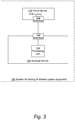
- the analyzer device 130 is for testing of wireless power equipment in the form of a wireless power transmitter device, such as device 20 in Figs. 1 and 2 , and/or a wireless power receiver device, such as device 10 in Figs. 1 and 2 .
- the analyzer device 130 comprises an interface 132 for receiving the electric signals generated by the pickup coil 112 of the probe device 110, when the probe device 110 is being placed between a surface of the housing of the wireless power transmitter device 20 and a surface of the housing of the wireless power receiver device 10 and is capturing electromagnetic signals 18 exchanged between the wireless power transmitter and receiver devices 20, 10 pursuant to the wireless power transfer protocol.
- the analyzer device 130 also comprises a processing unit 134 coupled to the interface 132 and configured for processing of the received electric signals.
- the processing unit 134 of the analyzer device 130 may be further configured for processing of the temperature measurements provided by the thermal sensor 116 of the probe device 110. This may serve to analyze the thermal environment of the region between the surfaces of the wireless power transmitter and receiver devices 20, 10, for instance as a result of one of them being subject to overheating caused by the wireless power transfer between the devices 20, 10.
- the probe device 110 and the analyzer device 130 constitutes a system 100 for testing of wireless power equipment in the form of a wireless power transmitter device, e.g. device 20, and/or a wireless power receiver device, e.g. device 10.
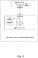
- the system 100 comprises means for causing manipulation of the electromagnetic signals exchanged 18 between the wireless power transmitter and receiver devices 20, 10.
- the means for causing manipulation of the electromagnetic signals may, for instance, comprise a resistive element 136 coupled to impose a controllable load on the pickup coil 112 of the probe device 110.
- resistive element 136 is indicated for the embodiment seen in Fig. 5 .
- the resistive element 136 is comprised in the analyzer device 130, thus being connected to the pickup coil 112 of the probe device 110 via the interfaces 132, 114 of the analyzer device 130 and the probe device 110, wherein the resistive element 136 is controllable by the processing unit 134 of the analyzer device 130.
- the resistive element 136 may be an external element connected to the analyzer device 130, thus being connected to the pickup coil 112 of the probe device 110 via the interfaces 132, 114 of the analyzer device 130 and the probe device 110, wherein the resistive element 136 is controllable by the processing unit 134 of the analyzer device 110 or by an external device comprising the resistive element 136.
- the resistive element 136 may be comprised in the probe device 110 and be coupled to the pickup coil 112 therein, wherein the resistive element 136 is controllable by the processing unit 134 of the analyzer device 130 via the interfaces 132, 114 of the analyzer device 130 and the probe device 110.
- the system 100 may be configured for controllable interception, e.g. by the resistive element 136, of wireless power transmitted by the wireless power transmitter device 20, so as to cause transfer of less wireless power than expected between the wireless power transmitter and receiver devices 20, 10.
- the means for causing manipulation of the electromagnetic signals 18 comprises an AM modulator 138 for causing an amplitude modulation of the electromagnetic signals exchanged between the wireless power transmitter and receiver devices 20, 10, wherein the AM modulator is controllable by the processing unit 134 of the analyzer device 130.
- the AM modulator 138 may be comprised in the analyzer device 130 (as seen in Fig. 6 ), or be comprised in the probe device 110, or in an external device connected to the analyzer device 130.
- the processing unit 134 of the analyzer device 130 may be configured to analyze the behavior of the wireless power receiver device 10 and/or the wireless power transmitter device 20 in reaction to the manipulation, by the means for causing manipulation (such as, for instance, the resistive element 136 or the AM modulator 138) of the electromagnetic signals 18 exchanged between the wireless power transmitter and receiver devices 20, 10, by examining the electric signals generated by the pickup coil 112 of the probe device 110.
- manipulation such as, for instance, the resistive element 136 or the AM modulator 138
- the system 100 may, for instance, be configured to test a foreign object detection, FOD, ability of the wireless power transmitter device 20 and/or wireless power receiver device 10 by emulating the presence of such a foreign object between the wireless power transmitter device 20 and wireless power receiver device 10 by the means 136, 138 for causing manipulation.
- FOD foreign object detection
- the processing unit 134 of the analyzer device 130 may be configured for controlling the means 136, 138 for causing manipulation to affect one or more data packets carried by the electromagnetic signals 18 between the wireless power transmitter and receiver devices 20, 10.
- One purpose may be to affect the at least one of the data packets so as to provoke non-compliance with the wireless power transfer protocol for the electromagnetic signals 18 between the wireless power transmitter and receiver devices 20, 10.
- a method 200 for testing of wireless power equipment in the form of a wireless power transmitter device (e.g. device 20) and/or a wireless power receiver device (e.g. device 10) is illustrated in Fig. 7 .
- the method 200 comprises a first step 210 of placing a probe device 110 having a pickup coil 112 between a surface of a housing of the wireless power transmitter device 20 and a surface of a housing of the wireless power receiver device 10.
- a second step 220 involves operating the wireless power transmitter device 20 and the wireless power receiver device 10 to communicate pursuant to a wireless power transfer protocol.
- a fourth step 240 the generated electric signals are then provided to an analyzer device 130.
- a fifth step 250 involves receiving, by the analyzer device 130, the generated electric signals from the probe device 110.
- a sixth step 260 the received electric signals are processed by the analyzer device 130.
- the steps of this method are performed without the wireless power transmitter device 20 and the wireless power receiver device 10 being able to notice that the probe device 110 is placed between them.
- This may, for instance, be used for testing the compliance of the wireless power transmitter device 20 and/or the wireless power receiver device 10 with the wireless power transfer protocol, such as WPC.
- the method 200 may be used for testing or tuning the performance by the wireless power transmitter device 20 when determining a reference quality factor of the wireless power receiver device 10. This will now be further explained.
- the (reference) quality factor of a wireless power receiver is often used to estimate the amount of losses or friendly metals in a power receiver product (PRx).
- a lower (reference) quality factor usually indicates higher losses in the PRx.
- PTx power transmitter products
- PRx power transmitter products
- the probe device 110 With the probe device 110 inserted in between the PTx and PRx it can utilize two different methods to reduce the reference quality factor of the PRx as measured/observed by the PTx. It can do this with much higher precision than the state-of-the art in emulating power losses in a wireless power system. This helps greatly in tuning and testing the performance of quality factor measurement in the PTx. It also facilitates much more precise testing of the impact of foreign objects in a wireless power system. Finally, it enables to emulate how PRx or PTx device deterioration will affect the system performance.
- one embodiment of the method 200 is directed at testing or tuning the performance by the wireless power transmitter device 20 when determining a reference quality factor of the wireless power receiver device 10.
- the testing or tuning involves controlling a controllable load (such as the aforementioned resistive element 136) of the pickup coil 112 of the probe device 110 to vary between a first load, such as infinite (open circuit), and a second lower load, such as 0 (short circuit).
- a controllable load such as the aforementioned resistive element 136
- This causes a controlled change in the (reference) quality factor observed by the wireless power transmitter device 20 between a first (reference) quality factor, such as Qo, and a second lower (reference) quality factor, such as 0.
- the testing or tuning involves adding pieces of conductive material, such as metal, to a planar non-conductive base sheet of the probe device 110.
- a controlled change is caused in the (reference) quality factor observed by the wireless power transmitter device 20 between a first (reference) quality factor, such as Qo, and a second lower (reference) quality factor, such as 0.
- embodiments of the present invention may be used with machine learning or artificial intelligence.
- knowledge may be developed on how to improve the safety, reliability or interoperability of wireless power equipment.
Landscapes
- Engineering & Computer Science (AREA)
- Physics & Mathematics (AREA)
- Computer Networks & Wireless Communication (AREA)
- General Physics & Mathematics (AREA)
- Power Engineering (AREA)
- Signal Processing (AREA)
- Electromagnetism (AREA)
- Charge And Discharge Circuits For Batteries Or The Like (AREA)
- Near-Field Transmission Systems (AREA)
- Telephonic Communication Services (AREA)
Priority Applications (5)
| Application Number | Priority Date | Filing Date | Title |
|---|---|---|---|
| JP2020566945A JP7324235B2 (ja) | 2018-06-01 | 2019-05-31 | 無線電力装置の試験システムおよび試験方法 |
| PCT/EP2019/064170 WO2019229229A1 (fr) | 2018-06-01 | 2019-05-31 | Système et procédé permettant de tester un équipement d'énergie sans fil |
| US17/059,848 US11956029B2 (en) | 2018-06-01 | 2019-05-31 | System and method for testing of wireless power equipment |
| KR1020207035874A KR102615470B1 (ko) | 2018-06-01 | 2019-05-31 | 무선전력장치의 검사를 위한 시스템 및 방법 |
| CN201980043322.5A CN112385149B (zh) | 2018-06-01 | 2019-05-31 | 用于无线电力设备测试的系统和方法 |
Applications Claiming Priority (1)
| Application Number | Priority Date | Filing Date | Title |
|---|---|---|---|
| EP18175611 | 2018-06-01 |
Publications (3)
| Publication Number | Publication Date |
|---|---|
| EP3576307A1 true EP3576307A1 (fr) | 2019-12-04 |
| EP3576307C0 EP3576307C0 (fr) | 2023-10-25 |
| EP3576307B1 EP3576307B1 (fr) | 2023-10-25 |
Family
ID=64172176
Family Applications (1)
| Application Number | Title | Priority Date | Filing Date |
|---|---|---|---|
| EP18204141.8A Active EP3576307B1 (fr) | 2018-06-01 | 2018-11-02 | Dispositif de sonde, dispositif d'analyse, système et procédé pour tester un équipement de transmission d'énergie sans fil |
Country Status (6)
| Country | Link |
|---|---|
| US (1) | US11956029B2 (fr) |
| EP (1) | EP3576307B1 (fr) |
| JP (1) | JP7324235B2 (fr) |
| KR (1) | KR102615470B1 (fr) |
| CN (1) | CN112385149B (fr) |
| WO (1) | WO2019229229A1 (fr) |
Cited By (2)
| Publication number | Priority date | Publication date | Assignee | Title |
|---|---|---|---|---|
| EP4020758A1 (fr) * | 2020-12-22 | 2022-06-29 | ElectDis AB | Système, dispositif de test maître, dispositif de test esclave et procédé de test d'équipement de transfert de puissance sans fil ayant une pluralité d'émetteurs de puissance sans fil |
| EP4084287A1 (fr) * | 2021-04-30 | 2022-11-02 | ElectDis AB | Dispositif de test pour tester un dispositif de puissance sans fil et procédé associé |
Families Citing this family (4)
| Publication number | Priority date | Publication date | Assignee | Title |
|---|---|---|---|---|
| US11437861B2 (en) * | 2018-08-22 | 2022-09-06 | Apple Inc. | Test object holder |
| US20210167637A1 (en) | 2019-12-03 | 2021-06-03 | Apple Inc. | Wireless Power Systems With Foreign Object Detection |
| EP3944508B1 (fr) * | 2020-07-23 | 2023-11-08 | ElectDis AB | Dispositif de test pour tester un dispositif de puissance sans fil et procédé associé |
| WO2025178179A1 (fr) * | 2024-02-21 | 2025-08-28 | 주식회사 부명 | Appareil d'inspection de batterie secondaire utilisant une mfc |
Citations (3)
| Publication number | Priority date | Publication date | Assignee | Title |
|---|---|---|---|---|
| US20150204949A1 (en) * | 2014-01-20 | 2015-07-23 | Qualcomm Incorporated | Methods and apparatus for wireless power field testing |
| EP3073609A1 (fr) * | 2015-03-23 | 2016-09-28 | nok9 AB | Dispositif de test pour transfert d'énergie sans fil et procédé associé |
| WO2018069478A1 (fr) * | 2016-10-12 | 2018-04-19 | Nok9 Ab | Système de test devant être utilisé pour tester un transfert d'énergie sans fil, et dispositif et procédé de test associés |
Family Cites Families (9)
| Publication number | Priority date | Publication date | Assignee | Title |
|---|---|---|---|---|
| US11329511B2 (en) * | 2006-06-01 | 2022-05-10 | Mojo Mobility Inc. | Power source, charging system, and inductive receiver for mobile devices |
| JP2010183705A (ja) | 2009-02-04 | 2010-08-19 | Seiko Epson Corp | 送電装置または受電装置のテスト方法、送電装置、受電装置および無接点電力伝送システム |
| WO2011156768A2 (fr) * | 2010-06-11 | 2011-12-15 | Mojo Mobility, Inc. | Système de transfert d'énergie sans fil prenant en charge l'interopérabilité et aimants multipolaires à utiliser avec ce système |
| US9496732B2 (en) * | 2011-01-18 | 2016-11-15 | Mojo Mobility, Inc. | Systems and methods for wireless power transfer |
| KR20250172698A (ko) | 2014-05-26 | 2025-12-09 | 지이 하이브리드 테크놀로지스, 엘엘씨 | 무선전력 수신 장치 및 무선 통신 방법 |
| SE1550754A1 (sv) * | 2015-06-08 | 2016-10-18 | Nok9 Ab | A testing device for wireless power transfer, and an associated method |
| CN206773017U (zh) | 2017-04-18 | 2017-12-19 | 东莞市沃德精密机械有限公司 | 手机无线充电线圈的测试治具 |
| US20190067979A1 (en) * | 2017-08-28 | 2019-02-28 | Wiwaves, Inc. | Wireless charging device and system |
| US10581282B2 (en) * | 2017-08-30 | 2020-03-03 | Nxp Usa, Inc. | Methods and systems for foreign objection detection in wireless energy transfer systems |
-
2018
- 2018-11-02 EP EP18204141.8A patent/EP3576307B1/fr active Active
-
2019
- 2019-05-31 WO PCT/EP2019/064170 patent/WO2019229229A1/fr not_active Ceased
- 2019-05-31 US US17/059,848 patent/US11956029B2/en active Active
- 2019-05-31 JP JP2020566945A patent/JP7324235B2/ja active Active
- 2019-05-31 CN CN201980043322.5A patent/CN112385149B/zh active Active
- 2019-05-31 KR KR1020207035874A patent/KR102615470B1/ko active Active
Patent Citations (3)
| Publication number | Priority date | Publication date | Assignee | Title |
|---|---|---|---|---|
| US20150204949A1 (en) * | 2014-01-20 | 2015-07-23 | Qualcomm Incorporated | Methods and apparatus for wireless power field testing |
| EP3073609A1 (fr) * | 2015-03-23 | 2016-09-28 | nok9 AB | Dispositif de test pour transfert d'énergie sans fil et procédé associé |
| WO2018069478A1 (fr) * | 2016-10-12 | 2018-04-19 | Nok9 Ab | Système de test devant être utilisé pour tester un transfert d'énergie sans fil, et dispositif et procédé de test associés |
Cited By (6)
| Publication number | Priority date | Publication date | Assignee | Title |
|---|---|---|---|---|
| EP4020758A1 (fr) * | 2020-12-22 | 2022-06-29 | ElectDis AB | Système, dispositif de test maître, dispositif de test esclave et procédé de test d'équipement de transfert de puissance sans fil ayant une pluralité d'émetteurs de puissance sans fil |
| WO2022136027A1 (fr) * | 2020-12-22 | 2022-06-30 | Electdis Ab | Système, dispositif d'essai maître, dispositif d'essai esclave et procédé de test d'un équipement de transfert d'énergie sans fil ayant une pluralité d'émetteurs d'énergie sans fil |
| US11675022B2 (en) | 2020-12-22 | 2023-06-13 | Electdis Ab | System, master test device, a slave test device and method for testing of wireless power transfer equipment having a plurality of wireless power transmitters |
| EP4084287A1 (fr) * | 2021-04-30 | 2022-11-02 | ElectDis AB | Dispositif de test pour tester un dispositif de puissance sans fil et procédé associé |
| WO2022228933A1 (fr) * | 2021-04-30 | 2022-11-03 | Electdis Ab | Dispositif de test pour tester un dispositif d'alimentation sans fil et procédé associé |
| EP4199309A1 (fr) * | 2021-04-30 | 2023-06-21 | ElectDis AB | Dispositif de test pour tester un dispositif d'alimentation sans fil et procédé associé |
Also Published As
| Publication number | Publication date |
|---|---|
| CN112385149B (zh) | 2022-09-30 |
| US11956029B2 (en) | 2024-04-09 |
| KR102615470B1 (ko) | 2023-12-19 |
| US20210226667A1 (en) | 2021-07-22 |
| JP2021526335A (ja) | 2021-09-30 |
| WO2019229229A1 (fr) | 2019-12-05 |
| KR20210019447A (ko) | 2021-02-22 |
| EP3576307C0 (fr) | 2023-10-25 |
| JP7324235B2 (ja) | 2023-08-09 |
| CN112385149A (zh) | 2021-02-19 |
| EP3576307B1 (fr) | 2023-10-25 |
Similar Documents
| Publication | Publication Date | Title |
|---|---|---|
| EP3576307B1 (fr) | Dispositif de sonde, dispositif d'analyse, système et procédé pour tester un équipement de transmission d'énergie sans fil | |
| JP6571738B2 (ja) | ワイヤレス給電の検査装置及び関連の方法 | |
| TWI488396B (zh) | 用於判定一配件是否包含特定電路之方法,系統及裝置 | |
| US20200355751A1 (en) | Testing device for testing wireless power transmitter device and associated method | |
| JP6886015B2 (ja) | 無線電力伝送の試験に使用するための試験システムならびに関連する試験装置および方法 | |
| CN113196716B (zh) | 在无线功率传输系统中的功率传输期间提供操作反馈的方法及装置 | |
| KR20220093139A (ko) | 복수의 무선 전력 송신기가 있는 전력 무선 전력 전송 장비를 테스트하기 위한 시스템, 마스터 테스트 장치, 슬레이브 테스트 장치 및 방법 | |
| EP3944508B1 (fr) | Dispositif de test pour tester un dispositif de puissance sans fil et procédé associé | |
| US9075425B2 (en) | Adjustable output power supply | |
| SE1451306A1 (sv) | A testing device for wireless power transfer, and an a: method | |
| CN211236054U (zh) | 无线充电测试设备 | |
| US11959992B2 (en) | Methods and systems for providing a secondary reference for evaluation of wireless power measuring accuracy, and for evaluating a power measuring accuracy of a wireless power measurement device under test | |
| WO2024080921A1 (fr) | Automatisation de test configurable |
Legal Events
| Date | Code | Title | Description |
|---|---|---|---|
| PUAI | Public reference made under article 153(3) epc to a published international application that has entered the european phase |
Free format text: ORIGINAL CODE: 0009012 |
|
| STAA | Information on the status of an ep patent application or granted ep patent |
Free format text: STATUS: THE APPLICATION HAS BEEN PUBLISHED |
|
| AK | Designated contracting states |
Kind code of ref document: A1 Designated state(s): AL AT BE BG CH CY CZ DE DK EE ES FI FR GB GR HR HU IE IS IT LI LT LU LV MC MK MT NL NO PL PT RO RS SE SI SK SM TR |
|
| AX | Request for extension of the european patent |
Extension state: BA ME |
|
| STAA | Information on the status of an ep patent application or granted ep patent |
Free format text: STATUS: REQUEST FOR EXAMINATION WAS MADE |
|
| 17P | Request for examination filed |
Effective date: 20200603 |
|
| RBV | Designated contracting states (corrected) |
Designated state(s): AL AT BE BG CH CY CZ DE DK EE ES FI FR GB GR HR HU IE IS IT LI LT LU LV MC MK MT NL NO PL PT RO RS SE SI SK SM TR |
|
| RAP1 | Party data changed (applicant data changed or rights of an application transferred) |
Owner name: ELECTDIS AB |
|
| STAA | Information on the status of an ep patent application or granted ep patent |
Free format text: STATUS: EXAMINATION IS IN PROGRESS |
|
| 17Q | First examination report despatched |
Effective date: 20210715 |
|
| GRAP | Despatch of communication of intention to grant a patent |
Free format text: ORIGINAL CODE: EPIDOSNIGR1 |
|
| STAA | Information on the status of an ep patent application or granted ep patent |
Free format text: STATUS: GRANT OF PATENT IS INTENDED |
|
| INTG | Intention to grant announced |
Effective date: 20230607 |
|
| GRAS | Grant fee paid |
Free format text: ORIGINAL CODE: EPIDOSNIGR3 |
|
| GRAA | (expected) grant |
Free format text: ORIGINAL CODE: 0009210 |
|
| STAA | Information on the status of an ep patent application or granted ep patent |
Free format text: STATUS: THE PATENT HAS BEEN GRANTED |
|
| AK | Designated contracting states |
Kind code of ref document: B1 Designated state(s): AL AT BE BG CH CY CZ DE DK EE ES FI FR GB GR HR HU IE IS IT LI LT LU LV MC MK MT NL NO PL PT RO RS SE SI SK SM TR |
|
| REG | Reference to a national code |
Ref country code: GB Ref legal event code: FG4D |
|
| REG | Reference to a national code |
Ref country code: CH Ref legal event code: EP |
|
| REG | Reference to a national code |
Ref country code: DE Ref legal event code: R096 Ref document number: 602018059867 Country of ref document: DE |
|
| REG | Reference to a national code |
Ref country code: IE Ref legal event code: FG4D |
|
| U01 | Request for unitary effect filed |
Effective date: 20231123 |
|
| U07 | Unitary effect registered |
Designated state(s): AT BE BG DE DK EE FI FR IT LT LU LV MT NL PT SE SI Effective date: 20231129 |
|
| U20 | Renewal fee for the european patent with unitary effect paid |
Year of fee payment: 6 Effective date: 20240115 |
|
| PG25 | Lapsed in a contracting state [announced via postgrant information from national office to epo] |
Ref country code: GR Free format text: LAPSE BECAUSE OF FAILURE TO SUBMIT A TRANSLATION OF THE DESCRIPTION OR TO PAY THE FEE WITHIN THE PRESCRIBED TIME-LIMIT Effective date: 20240126 |
|
| PG25 | Lapsed in a contracting state [announced via postgrant information from national office to epo] |
Ref country code: IS Free format text: LAPSE BECAUSE OF FAILURE TO SUBMIT A TRANSLATION OF THE DESCRIPTION OR TO PAY THE FEE WITHIN THE PRESCRIBED TIME-LIMIT Effective date: 20240225 |
|
| PG25 | Lapsed in a contracting state [announced via postgrant information from national office to epo] |
Ref country code: ES Free format text: LAPSE BECAUSE OF FAILURE TO SUBMIT A TRANSLATION OF THE DESCRIPTION OR TO PAY THE FEE WITHIN THE PRESCRIBED TIME-LIMIT Effective date: 20231025 |
|
| PG25 | Lapsed in a contracting state [announced via postgrant information from national office to epo] |
Ref country code: IS Free format text: LAPSE BECAUSE OF FAILURE TO SUBMIT A TRANSLATION OF THE DESCRIPTION OR TO PAY THE FEE WITHIN THE PRESCRIBED TIME-LIMIT Effective date: 20240225 Ref country code: GR Free format text: LAPSE BECAUSE OF FAILURE TO SUBMIT A TRANSLATION OF THE DESCRIPTION OR TO PAY THE FEE WITHIN THE PRESCRIBED TIME-LIMIT Effective date: 20240126 Ref country code: ES Free format text: LAPSE BECAUSE OF FAILURE TO SUBMIT A TRANSLATION OF THE DESCRIPTION OR TO PAY THE FEE WITHIN THE PRESCRIBED TIME-LIMIT Effective date: 20231025 |
|
| PG25 | Lapsed in a contracting state [announced via postgrant information from national office to epo] |
Ref country code: RS Free format text: LAPSE BECAUSE OF FAILURE TO SUBMIT A TRANSLATION OF THE DESCRIPTION OR TO PAY THE FEE WITHIN THE PRESCRIBED TIME-LIMIT Effective date: 20231025 Ref country code: PL Free format text: LAPSE BECAUSE OF FAILURE TO SUBMIT A TRANSLATION OF THE DESCRIPTION OR TO PAY THE FEE WITHIN THE PRESCRIBED TIME-LIMIT Effective date: 20231025 Ref country code: NO Free format text: LAPSE BECAUSE OF FAILURE TO SUBMIT A TRANSLATION OF THE DESCRIPTION OR TO PAY THE FEE WITHIN THE PRESCRIBED TIME-LIMIT Effective date: 20240125 Ref country code: HR Free format text: LAPSE BECAUSE OF FAILURE TO SUBMIT A TRANSLATION OF THE DESCRIPTION OR TO PAY THE FEE WITHIN THE PRESCRIBED TIME-LIMIT Effective date: 20231025 |
|
| REG | Reference to a national code |
Ref country code: CH Ref legal event code: PL |
|
| PG25 | Lapsed in a contracting state [announced via postgrant information from national office to epo] |
Ref country code: CH Free format text: LAPSE BECAUSE OF NON-PAYMENT OF DUE FEES Effective date: 20231130 |
|
| PG25 | Lapsed in a contracting state [announced via postgrant information from national office to epo] |
Ref country code: CZ Free format text: LAPSE BECAUSE OF FAILURE TO SUBMIT A TRANSLATION OF THE DESCRIPTION OR TO PAY THE FEE WITHIN THE PRESCRIBED TIME-LIMIT Effective date: 20231025 |
|
| REG | Reference to a national code |
Ref country code: DE Ref legal event code: R097 Ref document number: 602018059867 Country of ref document: DE |
|
| PG25 | Lapsed in a contracting state [announced via postgrant information from national office to epo] |
Ref country code: SK Free format text: LAPSE BECAUSE OF FAILURE TO SUBMIT A TRANSLATION OF THE DESCRIPTION OR TO PAY THE FEE WITHIN THE PRESCRIBED TIME-LIMIT Effective date: 20231025 |
|
| PG25 | Lapsed in a contracting state [announced via postgrant information from national office to epo] |
Ref country code: SM Free format text: LAPSE BECAUSE OF FAILURE TO SUBMIT A TRANSLATION OF THE DESCRIPTION OR TO PAY THE FEE WITHIN THE PRESCRIBED TIME-LIMIT Effective date: 20231025 Ref country code: SK Free format text: LAPSE BECAUSE OF FAILURE TO SUBMIT A TRANSLATION OF THE DESCRIPTION OR TO PAY THE FEE WITHIN THE PRESCRIBED TIME-LIMIT Effective date: 20231025 Ref country code: RO Free format text: LAPSE BECAUSE OF FAILURE TO SUBMIT A TRANSLATION OF THE DESCRIPTION OR TO PAY THE FEE WITHIN THE PRESCRIBED TIME-LIMIT Effective date: 20231025 Ref country code: CZ Free format text: LAPSE BECAUSE OF FAILURE TO SUBMIT A TRANSLATION OF THE DESCRIPTION OR TO PAY THE FEE WITHIN THE PRESCRIBED TIME-LIMIT Effective date: 20231025 Ref country code: CH Free format text: LAPSE BECAUSE OF NON-PAYMENT OF DUE FEES Effective date: 20231130 |
|
| PG25 | Lapsed in a contracting state [announced via postgrant information from national office to epo] |
Ref country code: MC Free format text: LAPSE BECAUSE OF FAILURE TO SUBMIT A TRANSLATION OF THE DESCRIPTION OR TO PAY THE FEE WITHIN THE PRESCRIBED TIME-LIMIT Effective date: 20231025 |
|
| PG25 | Lapsed in a contracting state [announced via postgrant information from national office to epo] |
Ref country code: MC Free format text: LAPSE BECAUSE OF FAILURE TO SUBMIT A TRANSLATION OF THE DESCRIPTION OR TO PAY THE FEE WITHIN THE PRESCRIBED TIME-LIMIT Effective date: 20231025 |
|
| PLBE | No opposition filed within time limit |
Free format text: ORIGINAL CODE: 0009261 |
|
| STAA | Information on the status of an ep patent application or granted ep patent |
Free format text: STATUS: NO OPPOSITION FILED WITHIN TIME LIMIT |
|
| REG | Reference to a national code |
Ref country code: IE Ref legal event code: MM4A |
|
| 26N | No opposition filed |
Effective date: 20240726 |
|
| PG25 | Lapsed in a contracting state [announced via postgrant information from national office to epo] |
Ref country code: IE Free format text: LAPSE BECAUSE OF NON-PAYMENT OF DUE FEES Effective date: 20231102 |
|
| PG25 | Lapsed in a contracting state [announced via postgrant information from national office to epo] |
Ref country code: IE Free format text: LAPSE BECAUSE OF NON-PAYMENT OF DUE FEES Effective date: 20231102 |
|
| U20 | Renewal fee for the european patent with unitary effect paid |
Year of fee payment: 7 Effective date: 20241118 |
|
| PG25 | Lapsed in a contracting state [announced via postgrant information from national office to epo] |
Ref country code: CY Free format text: LAPSE BECAUSE OF FAILURE TO SUBMIT A TRANSLATION OF THE DESCRIPTION OR TO PAY THE FEE WITHIN THE PRESCRIBED TIME-LIMIT; INVALID AB INITIO Effective date: 20181102 |
|
| PG25 | Lapsed in a contracting state [announced via postgrant information from national office to epo] |
Ref country code: HU Free format text: LAPSE BECAUSE OF FAILURE TO SUBMIT A TRANSLATION OF THE DESCRIPTION OR TO PAY THE FEE WITHIN THE PRESCRIBED TIME-LIMIT; INVALID AB INITIO Effective date: 20181102 |
|
| PG25 | Lapsed in a contracting state [announced via postgrant information from national office to epo] |
Ref country code: TR Free format text: LAPSE BECAUSE OF FAILURE TO SUBMIT A TRANSLATION OF THE DESCRIPTION OR TO PAY THE FEE WITHIN THE PRESCRIBED TIME-LIMIT Effective date: 20231025 |
|
| U20 | Renewal fee for the european patent with unitary effect paid |
Year of fee payment: 8 Effective date: 20251117 |
|
| PGFP | Annual fee paid to national office [announced via postgrant information from national office to epo] |
Ref country code: GB Payment date: 20251117 Year of fee payment: 8 |