EP3576326A1 - Procédé de transmission de données, équipement terminal et système de station de base - Google Patents
Procédé de transmission de données, équipement terminal et système de station de base Download PDFInfo
- Publication number
- EP3576326A1 EP3576326A1 EP18770577.7A EP18770577A EP3576326A1 EP 3576326 A1 EP3576326 A1 EP 3576326A1 EP 18770577 A EP18770577 A EP 18770577A EP 3576326 A1 EP3576326 A1 EP 3576326A1
- Authority
- EP
- European Patent Office
- Prior art keywords
- information
- control
- transmission mode
- terminal device
- configuration information
- Prior art date
- Legal status (The legal status is an assumption and is not a legal conclusion. Google has not performed a legal analysis and makes no representation as to the accuracy of the status listed.)
- Pending
Links
- 230000005540 biological transmission Effects 0.000 title claims abstract description 239
- 238000000034 method Methods 0.000 title claims abstract description 82
- 238000013507 mapping Methods 0.000 claims description 38
- 239000000969 carrier Substances 0.000 claims description 26
- 238000001514 detection method Methods 0.000 abstract description 22
- 230000002776 aggregation Effects 0.000 description 34
- 238000004220 aggregation Methods 0.000 description 34
- 238000012545 processing Methods 0.000 description 34
- 230000015654 memory Effects 0.000 description 33
- 230000006870 function Effects 0.000 description 23
- 238000010586 diagram Methods 0.000 description 16
- 238000013468 resource allocation Methods 0.000 description 15
- 238000004891 communication Methods 0.000 description 14
- 101150006914 TRP1 gene Proteins 0.000 description 10
- LVTKHGUGBGNBPL-UHFFFAOYSA-N Trp-P-1 Chemical compound N1C2=CC=CC=C2C2=C1C(C)=C(N)N=C2C LVTKHGUGBGNBPL-UHFFFAOYSA-N 0.000 description 10
- 238000005516 engineering process Methods 0.000 description 10
- 230000008569 process Effects 0.000 description 10
- 238000013461 design Methods 0.000 description 9
- 208000029632 chronic intestinal failure Diseases 0.000 description 8
- 238000004590 computer program Methods 0.000 description 8
- 230000011664 signaling Effects 0.000 description 7
- 101150071746 Pbsn gene Proteins 0.000 description 6
- 239000011159 matrix material Substances 0.000 description 6
- 230000009471 action Effects 0.000 description 5
- 238000007726 management method Methods 0.000 description 4
- LKKMLIBUAXYLOY-UHFFFAOYSA-N 3-Amino-1-methyl-5H-pyrido[4,3-b]indole Chemical compound N1C2=CC=CC=C2C2=C1C=C(N)N=C2C LKKMLIBUAXYLOY-UHFFFAOYSA-N 0.000 description 3
- 230000003287 optical effect Effects 0.000 description 3
- 230000001427 coherent effect Effects 0.000 description 2
- 238000011161 development Methods 0.000 description 2
- 230000007774 longterm Effects 0.000 description 2
- 239000013307 optical fiber Substances 0.000 description 2
- 230000002093 peripheral effect Effects 0.000 description 2
- 230000004044 response Effects 0.000 description 2
- 239000007787 solid Substances 0.000 description 2
- 238000004364 calculation method Methods 0.000 description 1
- 230000008859 change Effects 0.000 description 1
- 238000006243 chemical reaction Methods 0.000 description 1
- 238000013144 data compression Methods 0.000 description 1
- 238000013500 data storage Methods 0.000 description 1
- 238000000802 evaporation-induced self-assembly Methods 0.000 description 1
- 238000010295 mobile communication Methods 0.000 description 1
- 230000004048 modification Effects 0.000 description 1
- 238000012986 modification Methods 0.000 description 1
- 239000004065 semiconductor Substances 0.000 description 1
- 238000001228 spectrum Methods 0.000 description 1
- 230000007480 spreading Effects 0.000 description 1
Images




Classifications
-
- H—ELECTRICITY
- H04—ELECTRIC COMMUNICATION TECHNIQUE
- H04L—TRANSMISSION OF DIGITAL INFORMATION, e.g. TELEGRAPHIC COMMUNICATION
- H04L1/00—Arrangements for detecting or preventing errors in the information received
- H04L1/0001—Systems modifying transmission characteristics according to link quality, e.g. power backoff
- H04L1/0036—Systems modifying transmission characteristics according to link quality, e.g. power backoff arrangements specific to the receiver
- H04L1/0038—Blind format detection
-
- H—ELECTRICITY
- H04—ELECTRIC COMMUNICATION TECHNIQUE
- H04L—TRANSMISSION OF DIGITAL INFORMATION, e.g. TELEGRAPHIC COMMUNICATION
- H04L5/00—Arrangements affording multiple use of the transmission path
- H04L5/003—Arrangements for allocating sub-channels of the transmission path
- H04L5/0053—Allocation of signalling, i.e. of overhead other than pilot signals
-
- H—ELECTRICITY
- H04—ELECTRIC COMMUNICATION TECHNIQUE
- H04B—TRANSMISSION
- H04B7/00—Radio transmission systems, i.e. using radiation field
- H04B7/02—Diversity systems; Multi-antenna system, i.e. transmission or reception using multiple antennas
- H04B7/022—Site diversity; Macro-diversity
- H04B7/024—Co-operative use of antennas of several sites, e.g. in co-ordinated multipoint or co-operative multiple-input multiple-output [MIMO] systems
-
- H—ELECTRICITY
- H04—ELECTRIC COMMUNICATION TECHNIQUE
- H04L—TRANSMISSION OF DIGITAL INFORMATION, e.g. TELEGRAPHIC COMMUNICATION
- H04L1/00—Arrangements for detecting or preventing errors in the information received
- H04L1/0001—Systems modifying transmission characteristics according to link quality, e.g. power backoff
- H04L1/0036—Systems modifying transmission characteristics according to link quality, e.g. power backoff arrangements specific to the receiver
- H04L1/0039—Systems modifying transmission characteristics according to link quality, e.g. power backoff arrangements specific to the receiver other detection of signalling, e.g. detection of TFCI explicit signalling
-
- H—ELECTRICITY
- H04—ELECTRIC COMMUNICATION TECHNIQUE
- H04L—TRANSMISSION OF DIGITAL INFORMATION, e.g. TELEGRAPHIC COMMUNICATION
- H04L5/00—Arrangements affording multiple use of the transmission path
- H04L5/0001—Arrangements for dividing the transmission path
- H04L5/0003—Two-dimensional division
- H04L5/0005—Time-frequency
- H04L5/0007—Time-frequency the frequencies being orthogonal, e.g. OFDM(A) or DMT
- H04L5/001—Time-frequency the frequencies being orthogonal, e.g. OFDM(A) or DMT the frequencies being arranged in component carriers
-
- H—ELECTRICITY
- H04—ELECTRIC COMMUNICATION TECHNIQUE
- H04L—TRANSMISSION OF DIGITAL INFORMATION, e.g. TELEGRAPHIC COMMUNICATION
- H04L5/00—Arrangements affording multiple use of the transmission path
- H04L5/003—Arrangements for allocating sub-channels of the transmission path
- H04L5/0032—Distributed allocation, i.e. involving a plurality of allocating devices, each making partial allocation
- H04L5/0035—Resource allocation in a cooperative multipoint environment
-
- H—ELECTRICITY
- H04—ELECTRIC COMMUNICATION TECHNIQUE
- H04L—TRANSMISSION OF DIGITAL INFORMATION, e.g. TELEGRAPHIC COMMUNICATION
- H04L5/00—Arrangements affording multiple use of the transmission path
- H04L5/003—Arrangements for allocating sub-channels of the transmission path
- H04L5/0048—Allocation of pilot signals, i.e. of signals known to the receiver
-
- H—ELECTRICITY
- H04—ELECTRIC COMMUNICATION TECHNIQUE
- H04L—TRANSMISSION OF DIGITAL INFORMATION, e.g. TELEGRAPHIC COMMUNICATION
- H04L5/00—Arrangements affording multiple use of the transmission path
- H04L5/0091—Signalling for the administration of the divided path, e.g. signalling of configuration information
- H04L5/0094—Indication of how sub-channels of the path are allocated
-
- H—ELECTRICITY
- H04—ELECTRIC COMMUNICATION TECHNIQUE
- H04W—WIRELESS COMMUNICATION NETWORKS
- H04W72/00—Local resource management
- H04W72/04—Wireless resource allocation
- H04W72/044—Wireless resource allocation based on the type of the allocated resource
- H04W72/0453—Resources in frequency domain, e.g. a carrier in FDMA
-
- H—ELECTRICITY
- H04—ELECTRIC COMMUNICATION TECHNIQUE
- H04W—WIRELESS COMMUNICATION NETWORKS
- H04W72/00—Local resource management
- H04W72/12—Wireless traffic scheduling
- H04W72/121—Wireless traffic scheduling for groups of terminals or users
-
- H—ELECTRICITY
- H04—ELECTRIC COMMUNICATION TECHNIQUE
- H04W—WIRELESS COMMUNICATION NETWORKS
- H04W72/00—Local resource management
- H04W72/20—Control channels or signalling for resource management
- H04W72/23—Control channels or signalling for resource management in the downlink direction of a wireless link, i.e. towards a terminal
-
- H—ELECTRICITY
- H04—ELECTRIC COMMUNICATION TECHNIQUE
- H04W—WIRELESS COMMUNICATION NETWORKS
- H04W72/00—Local resource management
- H04W72/04—Wireless resource allocation
- H04W72/044—Wireless resource allocation based on the type of the allocated resource
- H04W72/0466—Wireless resource allocation based on the type of the allocated resource the resource being a scrambling code
Definitions
- This application relates to the field of technologies, and in particular, to a data transmission method, a terminal device, and a base station system.
- a cell may configure one or more control resource sets (Control Resource Set, CORESET for short) for each user equipment (User Equipment, UE for short), and one CORESET is defined as several physical resource blocks (Physical resource block, PRB for short) in frequency domain.
- the UE monitors the one or more configured CORESETs, and blindly detects a downlink control channel in the CORESETs.
- a cell may configure, for UE, one or two enhanced physical downlink control channel (Enhanced Physical Downlink Control Channel, EPDCCH for short) sets that need to be monitored, and an EPDCCH can be transmitted in only these sets.
- One EPDCCH set includes two, four, or eight PRB pairs (pair). Different quantities of PRB pairs may be configured for different EPDCCH sets.
- downlink control channels Downlink Control Information, DCI for short
- the UE blindly detects two pieces of DCI in a first EPDCCH set.
- the UE blindly detects the undetected DCI in a second EPDCCH set. Therefore, to reduce a quantity of blind detection times, a same payload (payload) size is set for the downlink control channels corresponding to the two EPDCCH sets in LTE.
- This application provides a data transmission method, a terminal device, a base station, and a base station system, to provide a method for transmitting and detecting control information in NR.
- this application provides a data transmission method, and the method includes:
- a sum of a size of the first control channel candidate set and a size of the second control channel candidate set is not greater than a first threshold.
- the base station sends the first configuration information and the second configuration information to the terminal device, the first configuration information includes the information about the first control resource set, the second configuration information includes the information about the second control resource set, and the sum of the size of the first control channel candidate set and the size of the second control channel candidate set is not greater than the first threshold.
- the terminal device needs to detect the first control information in only the first control channel candidate set corresponding to the first control resource set, and detect the second control information in only the second control channel candidate set corresponding to the second control resource set.
- a same payload (payload) size is set for downlink control channels corresponding to two EPDCCH sets in LTE.
- the terminal device needs to detect the first control information in only the first control channel candidate set, and detect the second control information in only the second control channel candidate set. Therefore, in this application, a quantity of blind detection times does not increase even if a payload size of the first control information is different from that of the second control information.
- a payload length of the first control information is different from that of the second control information.
- a quantity of blind detection times of the terminal device does not increase even if the payload length of the first control information is different from that of the second control information, and therefore, the quantity of blind detection times is better controlled.
- the first configuration information further includes first transmission mode information associated with the first control information
- the second configuration information further includes second transmission mode information associated with the second control information
- the method further includes: receiving, by the terminal device, third configuration information from the base station, where the third configuration information includes first transmission mode information associated with the first control information and second transmission mode information associated with the second control information.
- the first transmission mode information is a transmission mode, or the first transmission mode information is one or more of a resource mapping manner, a demodulation reference signal DMRS scrambling code sequence, and quasi co-location QCL.
- the second transmission mode information is a transmission mode; or the second transmission mode information is one or more of a resource mapping manner, a DMRS scrambling code sequence, and QCL.
- the first control resource set and the second control resource set belong to different carriers.
- the data transmission method provided in this application for reducing a quantity of blind detection times of a terminal device is also applicable.
- this application provides a terminal device.
- the terminal device includes a plurality of functional modules, configured to implement any data transmission method provided in the first aspect, so that the terminal device receives first configuration information and second configuration information sent by a base station.
- the first configuration information includes information about a first control resource set
- the second configuration information includes information about a second control resource set
- a sum of a size of a first control channel candidate set and a size of a second control channel candidate set is not greater than a first threshold.
- the terminal device needs to detect first control information in only the first control channel candidate set corresponding to the first control resource set, and detect second control information in only the second control channel candidate set corresponding to the second control resource set.
- a same payload (payload) size is set for downlink control channels corresponding to two EPDCCH sets in LTE.
- the terminal device needs to detect the first control information in only the first control channel candidate set, and detect the second control information in only the second control channel candidate set. Therefore, in this application, a quantity of blind detection times does not increase even if a payload size of the first control information is different from that of the second control information.
- a structure of the terminal device includes a processor and a transceiver.
- the processor is configured to support the terminal device in performing corresponding functions in the data transmission method in the first aspect.
- the transceiver is configured to: support communication between the terminal device and the base station, and receive information or an instruction that is related to the foregoing data transmission method and that is sent by the base station.
- the terminal device may further include a memory.
- the memory is coupled to the processor, and the memory stores a program instruction and data that are necessary for the terminal device.
- the transceiver is configured to receive first configuration information and second configuration information from the base station, where the first configuration information includes information about a first control resource set, and the second configuration information includes information about a second control resource set.
- the processor is configured to: detect first control information in a first control channel candidate set corresponding to the first control resource set, and detect second control information in a second control channel candidate set corresponding to the second control resource set, where a sum of a size of the first control channel candidate set and a size of the second control channel candidate set is not greater than a first threshold.
- a payload length of the first control information is different from that of the second control information.
- the first configuration information further includes first transmission mode information associated with the first control information
- the second configuration information further includes second transmission mode information associated with the second control information
- the transceiver is further configured to receive third configuration information from the base station, where the third configuration information includes first transmission mode information associated with the first control information and second transmission mode information associated with the second control information.
- the first transmission mode information is a transmission mode; or the first transmission mode information is one or more of a resource mapping manner, a demodulation reference signal DMRS scrambling code sequence, and quasi co-location QCL.
- the second transmission mode information is a transmission mode; or the second transmission mode information is one or more of a resource mapping manner, a DMRS scrambling code sequence, and QCL.
- the first control resource set and the second control resource set belong to different carriers.
- this application provides a data transmission method, and the method includes:
- This application provides the data transmission method. Based on the method in this application, the base station sends only one piece of control information in a control channel candidate set corresponding to one control resource set, for example, sends the first control information in the first control channel candidate set, and sends the second control information in the second control channel candidate set, or sends the second control information in the first control channel candidate set, and sends the first control information in the second control channel candidate set. Therefore, the terminal device detects the first control information and the second control information in the first control channel candidate set. If the first control information is successfully detected in the first control channel candidate set, the terminal device needs to detect only the second control information in the second control channel candidate set. If the second control information is successfully detected in the first control channel candidate set, the terminal device needs to detect only the first control information in the second control channel candidate set.
- a payload length of the first control information is the same as that of the second control information.
- the first control resource set and the second control resource set belong to different carriers.
- this application provides a terminal device.
- the terminal device includes a plurality of functional modules, configured to implement any data transmission method provided in the third aspect.
- a base station sends only one piece of control information in a control channel candidate set corresponding to one control resource set, for example, sends first control information in a first control channel candidate set, and sends second control information in a second control channel candidate set, or sends second control information in a first control channel candidate set, and sends first control information in a second control channel candidate set. Therefore, the terminal device detects the first control information and the second control information in the first control channel candidate set.
- the terminal device needs to detect only the second control information in the second control channel candidate set. If the second control information is successfully detected in the first control channel candidate set, the terminal device needs to detect only the first control information in the second control channel candidate set.
- a structure of the terminal device includes a processor and a transceiver.
- the processor is configured to support the terminal device in performing corresponding functions in the data transmission method in the third aspect.
- the transceiver is configured to: support communication between the terminal device and the base station, and receive information or an instruction that is related to the foregoing data transmission method and that is sent by the base station.
- the terminal device may further include a memory.
- the memory is coupled to the processor, and the memory stores a program instruction and data that are necessary for the terminal device.
- the transceiver is configured to receive first configuration information and second configuration information from the base station, where the first configuration information includes information about a first control resource set, and the second configuration information includes information about a second control resource set.
- the processor is configured to: detect the first control information and the second control information in the first control channel candidate set corresponding to the first control resource set; and if the first control information is successfully detected, detect the second control information in the second control channel candidate set corresponding to the second control resource set; or if the second control information is successfully detected, detect the first control information in the second control channel candidate set, where a sum of a size of the first control channel candidate set and a size of the second control channel candidate set is not greater than a first threshold.
- a payload length of the first control information is the same as that of the second control information.
- the first control resource set and the second control resource set belong to different carriers.
- this application provides a data transmission method, including:
- the first configuration information further includes first transmission mode information associated with the first control information
- the second configuration information further includes second transmission mode information associated with the second control information
- the method further includes: sending, by the first base station, third configuration information to the terminal device, where the third configuration information includes first transmission mode information associated with the first control information and second transmission mode information associated with the second control information.
- the first transmission mode information is a transmission mode; or the first transmission mode information is one or more of a resource mapping manner, a DMRS scrambling code sequence, and QCL.
- the second transmission mode information is a transmission mode; or the second transmission mode information is one or more of a resource mapping manner, a DMRS scrambling code sequence, and QCL.
- the first control resource set and the second control resource set belong to different carriers.
- this application provides a base station system, including a first base station and a second base station.
- the first base station is configured to send first configuration information and second configuration information to a terminal device, where the first configuration information includes information about a first control resource set, and the second configuration information includes information about a second control resource set.
- the first base station is further configured to send first control information to the terminal device in a first control channel candidate set corresponding to the first control resource set.
- the second base station is configured to send second control information to the terminal device in a second control channel candidate set corresponding to the second control resource set, where a sum of a size of the first control channel candidate set and a size of the second control channel candidate set is not greater than a first threshold.
- the first configuration information further includes first transmission mode information associated with the first control information
- the second configuration information further includes second transmission mode information associated with the second control information
- the first base station is further configured to send third configuration information to the terminal device, where the third configuration information includes first transmission mode information associated with the first control information and second transmission mode information associated with the second control information.
- the first transmission mode information is a transmission mode; or the first transmission mode information is one or more of a resource mapping manner, a DMRS scrambling code sequence, and QCL.
- the second transmission mode information is a transmission mode; or the second transmission mode information is one or more of a resource mapping manner, a DMRS scrambling code sequence, and QCL.
- the first control resource set and the second control resource set belong to different carriers.
- This application further provides a base station, and the base station may perform a method performed by the first base station in the sixth aspect.
- This application further provides a base station, and the base station may perform a method performed by the second base station in the sixth aspect.
- an embodiment of this application provides a computer storage medium, configured to store a computer software instruction used by the terminal device provided in the second aspect, the terminal device provided in the fourth aspect, or the base station system provided in the sixth aspect.
- the computer software instruction includes a program designed for performing the first aspect, the third aspect, or the fifth aspect.
- this application further provides a computer program product including an instruction.
- the computer program product runs on a computer, the computer is enabled to perform the method in the first aspect, the third aspect, or the fifth aspect.
- Embodiments of this application are applicable to a 5G system (5th generation mobile communications system), for example, a communications system such as an access network using new radio (New Radio, NR for short) or a cloud radio access network (Cloud Radio Access Network, CRAN for short), or may be applied to a future communications system above 5G.
- 5G system 5th generation mobile communications system
- a communications system such as an access network using new radio (New Radio, NR for short) or a cloud radio access network (Cloud Radio Access Network, CRAN for short)
- CRAN Cloud Radio Access Network
- the network architecture and the service scenario described in the embodiments of this application are intended to describe the technical solutions in the embodiments of this application more clearly, and do not constitute a limitation on the technical solutions provided in the embodiments of this application.
- a person of ordinary skill in the art may know that: With the evolution of the network architecture and the emergence of new service scenarios, the technical solutions provided in the embodiments of this application are also applicable to similar technical problems.
- FIG. 1 is a schematic diagram of a possible application scenario according to this application.
- a radio access network Radio access network, RAN for short.
- the RAN includes at least one base station (base station, BS for short) 20.
- base station base station
- BS base station
- the RAN is connected to a core network (core network, CN for short).
- the CN may be coupled to one or more external networks (External Network) such as the Internet and a public switched telephone network (public switched telephone network, PSTN for short).
- External Network such as the Internet and a public switched telephone network (public switched telephone network, PSTN for short).
- FIG. 2 is an architectural diagram of a system to which this application is applicable.
- the system includes the following network elements:
- the search space For the search space, the following describes the search space separately in a carrier aggregation (Carrier Aggregation, CA for short) scenario and a non-carrier aggregation scenario.
- Carrier Aggregation CA for short
- CA Carrier Aggregation
- the non-carrier aggregation scenario namely, a scenario in which UE has only one carrier, is first discussed.
- the search space defines a search manner and a start location at which the UE blindly detects a downlink control channel.
- the UE monitors a downlink control channel candidate set in a non-discontinuous reception (English: non-discontinuous reception, non-DRX for short) subframe. This means that the UE needs to attempt to decode each downlink control channel in the set based on a format of DCI that needs to be listened to.
- the set is the search space of the UE.
- Search space S k L at an aggregation level L (for example, ⁇ 1, 2, 4, 8 ⁇ ) is defined as the downlink control channel candidate set.
- the search space is divided into common search space (Common search space) and UE-specific search space (UE-specific search space).
- the common search space is used to transmit control information (cell-level common information) related to paging, a random access response (Random Access Response, RAR), a broadcast control channel (Broadcast Control Channel, BCCH for short), and the like.
- the information is the same for all UEs.
- the UE-specific search space is used to transmit control information (UE-level information) related to a downlink shared channel (Downlink share channel, DL-SCH for short), an uplink shared channel (Uplink share channel, UL-SCH for short), and the like.
- An EPDCCH is also used as an example. It should be noted that the EPDCCH includes only UE-specific search space.
- the two EPDCCH sets may have different transmission parameters (for example, centralized/distributed resource mapping, a DMRS scrambling sequence, and quasi co-location (QCL, Quasi Co-Located)).
- EPDCCH candidate sets need to be divided into different EPDCCH sets. For example, when the two EPDCCH sets respectively include four PRB pairs and two PRB pairs, EPDCCH candidate sets in the EPDCCH sets are respectively ⁇ 4, 4, 1, 1 ⁇ and ⁇ 2, 2, 1, 1 ⁇ .
- the following describes the search space in the carrier aggregation scenario.
- UE monitors search space of all activated carriers (including one primary carrier (Primary Carrier, PCarrier for short) and numOfActivatedDlSCarrier secondary carriers (Secondary Carrier, SCarrier for short)) in each non-DRX subframe. Based on whether the UE is configured with cross-carrier scheduling, there may be the following several cases.
- the UE does not know a value of the CIF field carried in the downlink control channel, to be specific, does not know a specific carrier used to send the downlink control channel to the UE.
- the UE knows only a set of CIFs that may be carried in a downlink control channel sent on each specific carrier to the UE. Therefore, the UE tries all possible CIF values on the carrier to blindly detect the downlink control channel. Therefore, a maximum quantity of times of blind detection that needs to be performed by the UE configured with CA in UE-specific search space is directly proportional to a quantity of activated carriers, to be specific, is 32 + 32 x numOfActivatedDlSCarrier.
- a coordinated multipoint transmission/reception (Coordinated Multiple Points Transmission/Reception, CoMP for short) technology implements coordinated transmission between transmission points at different geographical locations.
- the transmission points exchange information to avoid mutual interference, so as to improve quality of service and a throughput for a user.
- Current mainstream CoMP technology implementations may be classified into a joint processing (Joint Processing, JP for short) technology and a coordinated scheduling/coordinated beamforming (Coordinated Scheduling/Beamforming, CS/CB for short) technology.
- a core idea of the JP technology is that all transmission points in a coordinated cell cluster share, on a same resource block, data used for transmission of UE. In other words, the data of the UE is available on a plurality of transmission points. Based on whether data transmitted by a user is from different transmission points at the same time, the JP technology may be classified into two types: a JT technology and dynamic point selection (Dynamic Point Select, DPS for short).
- a JT transmission mode a plurality of transmission points send data for same UE on a same time-frequency resource.
- a previous inter-cell interference signal is converted into a desired signal to improve performance of a cell edge user.
- JT may be classified into two types: coherent transmission and incoherent transmission.
- incoherent transmission JT each transmission point uses an independent precoding scheme, and a signal is received at a receive end, to implement bit-level combination.
- the CoMP technology is implemented based on an ideal backhaul link. Therefore, when a plurality of transmission points provide coordinated data transmission for same UE, the UE receives DCI from only a serving transmission point.
- the DCI includes scheduling information of the serving transmission point and another transmission point that provides coordinated transmission for the UE.
- the UE receives control information delivered by the serving transmission point, and receives, based on scheduling information that is of each transmission point participating in coordinated transmission and that is included in the control information, data transmitted by each transmission point.
- CSI Channel State Information
- the UE is supported in receiving a plurality of different data streams in a coordinated manner by using a plurality of transmission points connected based on a non-ideal backhaul link.
- the UE not only needs to receive the DCI from the serving transmission point, but also needs to receive DCI from one or more coordinated transmission points.
- DCI information included in both EPDCCH sets is the same.
- the UE blindly detects one piece of DCI in the EPDCCH sets if the UE successfully detects the DCI in a first EPDCCH set blindly, the UE no longer performs detection in a second EPDCCH set, or if the UE blindly detects no DCI in a first EPDCCH set, the UE further performs blind detection in a second EPDCCH set.
- the UE When the UE blindly detects a plurality of pieces of DCI in the two EPDCCH sets, the UE needs to blindly detect DCI in all formats in a first EPDCCH set, and if all the DCI is successfully detected blindly, the UE no longer performs blind detection in a second EPDCCH set, or if there is DCI that is not blindly detected, the UE needs to continue to perform blind detection in a second EPDCCH set. In this case, to ensure that a quantity of blind detection times of the UE in one carrier does not increase, the plurality of pieces of DCI need to have a same payload size (payload size).
- a terminal In incoherent joint transmission (Joint Transmission, JT for short) based on a non-ideal backhaul link, a terminal needs to separately receive, in a plurality of CORESETs, control information sent from a plurality of transmission points including a serving transmission point and a coordinated transmission point, so as to schedule data transmission on a same carrier.
- JT transmission how to exchange control information between a base station and a terminal device is a problem to be resolved.
- the serving transmission point TRP 1 sends configuration information through broadcast or higher layer signaling, to configure one CORESET for the UE.
- the configuration information further includes transmission parameter information of the CORESET.
- the transmission parameter information includes one or more of resource allocation information (distributed/centralized), a used demodulation reference signal (Demodulation Reference Signal, DMRS for short) scrambling sequence, quasi co-location (Quasi Co-Located, QCL for short), and other information.
- the resource allocation information includes a transmission mode.
- the CORESET uses a centralized resource mapping manner, and occupies a 5 MHz bandwidth in frequency domain, and the transmission mode is TM5.
- the UE deduces the used transmission mode based on one or more of the resource allocation information, the DMRS scrambling sequence, and the QCL, or directly obtains the transmission mode from the configuration information. Then, the UE determines, based on a type of information expected to be received and the transmission mode, a format of DCI to be blindly detected, and blindly detects the DCI in the CORESET.
- the terminal device blindly detects the DCI on six control channel candidates corresponding to an aggregation level 1, six control channel candidates corresponding to an aggregation level 2, two control channel candidates corresponding to an aggregation level 4, and two control channel candidates corresponding to an aggregation level 8 in the CORESET.
- RNTI Radio Network Temporary Identity
- a case in which UE has two transmission points is described in the embodiments of this application.
- One of the two transmission points is a serving transmission point (which is referred to as a TRP 1 or a first base station below), and the other transmission point is a coordinated transmission point (which is referred to as a TRP 2 or a second base station below).
- TRP 1 serving transmission point
- TRP 2 coordinated transmission point
- the serving transmission point sends first configuration information and second configuration information to the UE.
- the first configuration information includes information about a first control resource set (CORESET 1)
- the second configuration information includes information about a second control resource set (CORESET 2).
- the TRP 1 may configure the CORESET 1 and the CORESET 2 for the UE through broadcast or higher layer signaling.
- the TRP 1 and the TRP 2 communicate with the UE in a coordinated manner.
- the CORESET 1 and the CORESET 2 belong to a same carrier (CC1).
- the TRP 1 sends first configuration information and second configuration information to the UE.
- the first configuration information includes information about a first control resource set (CORESET 1)
- the second configuration information includes information about a second control resource set (CORESET 2).
- the TRP 1 may configure the CORESET 1 and the CORESET 2 for the UE through broadcast or higher layer signaling.
- the TRP 1 and the TRP 2 communicate with the UE in a coordinated manner.
- the CORESET 1 belongs to a carrier 1 (CC1), and downlink data in the carrier 1 (CC1) is scheduled by using the local carrier.
- the CORESET 2 belongs to a carrier 2 (CC2), and downlink data in the carrier 1 (CC1) is scheduled in a cross-carrier manner.
- a sum of a size of a first control channel candidate set corresponding to the CORESET 1 and a size of a second control channel candidate set corresponding to the CORESET 2 is not greater than a first threshold.
- a corresponding parameter in the foregoing Table 9.1.4-2b may change. Therefore, a specific value of the first threshold in the embodiments of this application may be correspondingly adjusted with the development of the communications standards.
- the CORESET 1 and the CORESET 2 belong to a same carrier.
- FIG. 5 shows a first data transmission method in the first case, and the method includes the following steps.
- Step 501 A first base station sends first configuration information and second configuration information to a terminal device.
- the first base station is a serving transmission point (TRP 1)
- the first configuration information includes information about a first control resource set (CORESET 1)
- the second configuration information includes information about a second control resource set (CORESET 2).
- Step 502 The terminal device receives the first configuration information and the second configuration information.
- Step 503 The first base station sends first control information to the terminal device in a first control channel candidate set, and a second base station sends second control information to the terminal device in a second control channel candidate set.
- Step 504 The terminal device detects the first control information in the first control channel candidate set, and detects the second control information in the second control channel candidate set.
- the terminal learns in advance that the first control information is delivered by using the CORESET 1, and that the second control information is delivered by using the CORESET 2. Therefore, when performing DCI blind detection, the terminal device detects the first control information in only the first control channel candidate set, detects the second control information in only the second control channel candidate set, and does not need to detect both the first control information and the second control information in the first control channel candidate set, so that a quantity of blind detection times can be reduced.
- the terminal may learn, in the following manners, that the first control information is delivered by using the CORESET 1 and that the second control information is delivered by using the CORESET 2.
- Manner 1 The terminal learns, by using the first configuration information and the second configuration information, that the first control information is delivered by using the CORESET 1 and that the second control information is delivered by using the CORESET 2.
- the first configuration information further includes first transmission mode information associated with the first control information
- the second configuration information further includes second transmission mode information associated with the second control information.
- the terminal device may learn, by using the first transmission mode information, that the first control information is delivered by using the CORESET 1, and when receiving the second transmission mode information, may learn, by using the second transmission mode information, that the second control information is delivered by using the CORESET 2.
- the first transmission mode information is a transmission mode; or the first transmission mode information is one or more of a resource mapping manner, a DMRS scrambling code sequence, and QCL.
- the terminal device may deduce a transmission mode, and then learn, based on the transmission mode, that the first control information is delivered in the first control channel candidate set. If the first transmission mode information obtained by the terminal device is directly the transmission mode, the terminal device learns, based on the transmission mode, that the first control information is delivered in the first control channel candidate set.
- the second transmission mode information is a transmission mode; or the second transmission mode information is one or more of a resource mapping manner, a DMRS scrambling code sequence, and QCL.
- the terminal device may deduce a transmission mode, and then learn, based on the transmission mode, that the second control information is delivered in the second control channel candidate set. If the second transmission mode information obtained by the terminal device is directly the transmission mode, the terminal device learns, based on the transmission mode, that the second control information is delivered in the second control channel candidate set.
- Resource mapping manners are divided into centralized mapping and distributed mapping.
- Manner 2 The terminal learns, by using third configuration information, that the first control information is delivered by using the CORESET 1 and that the second control information is delivered by using the CORESET 2.
- the first base station further sends the third configuration information to the terminal device, and the third configuration information includes first transmission mode information associated with the first control information and second transmission mode information associated with the second control information.
- the first base station sends the first transmission mode information and the second transmission mode information to the terminal device by separately delivering the third configuration information
- the first transmission mode information indicates that the first base station delivers the first control information in the CORESET 1
- the second transmission mode information indicates that the second base station delivers the second control information in the CORESET 2.
- the terminal device determines, based on received configuration information, that DCI 1 needs to be blindly detected in the first control channel candidate set corresponding to the CORESET 1 delivered by the first base station, and DCI 2 needs to be blindly detected in the second control channel candidate set corresponding to the CORESET 2 delivered by the second base station.
- the DCI 1 is blindly detected in four control channel candidate sets corresponding to an aggregation level 1, four control channel candidate sets corresponding to an aggregation level 2, zero control channel candidate sets corresponding to an aggregation level 4, and zero control channel candidate sets corresponding to an aggregation level 8 in the CORESET 1
- the DCI 2 is blindly detected in two control channel candidates corresponding to the aggregation level 1, three control channel candidates corresponding to the aggregation level 2, two control channel candidates corresponding to the aggregation level 4, and one control channel candidate corresponding to the aggregation level 8 in the CORESET 2.
- control channel candidate sets are divided into the CORESET 1 and the CORESET 2.
- a payload length of the first control information may be the same as or different from that of the second control information.
- a quantity of DCI blind detection times does not increase.
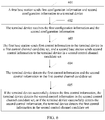
- FIG. 6 shows a second data transmission method in the first case, and the method includes the following steps.
- Step 601 A first base station sends first configuration information and second configuration information to a terminal device.
- the first base station is a serving transmission point (TRP 1)
- the first configuration information includes information about a first control resource set (CORESET 1)
- the second configuration information includes information about a second control resource set (CORESET 2).
- Step 602 The terminal device receives the first configuration information and the second configuration information.
- Step 603 The first base station sends first control information to the terminal device in a first control channel candidate set, and a second base station sends second control information to the terminal device in a second control channel candidate set.
- Step 604 The terminal device detects the first control information and the second control information in the first control channel candidate set.
- Step 605 If the terminal device successfully detects the first control information, the terminal device detects the second control information in the second control channel candidate set, or if the terminal device successfully detects the second control information, the terminal device detects the first control information in the second control channel candidate set.
- the data transmission method shown in FIG. 6 is mainly applicable to a scenario in which the terminal device has a plurality of transmission points. Specifically, in the method, the terminal device does not know whether the first control information is sent in the CORESET 1 or the CORESET 2, and whether the first control information is sent in the CORESET 1 or the CORESET 2. However, the terminal device knows that there is only one piece of control information in each of the CORESET 1 and the CORESET 2. For example, the CORESET 1 includes the first control information, and the CORESET 2 includes the second control information, or the CORESET 1 includes the second control information, and the CORESET 2 includes the first control information.
- the terminal device first detects the first control information and the second control information in the first control channel candidate set. If the first control information is successfully detected, the terminal device detects the second control information in the second control channel candidate set. If the second control information is successfully detected, the terminal device detects the first control information in the second control channel candidate set.
- the terminal device determines that control information delivered by the first base station and the second base station is DCI 1 and DCI 2, the terminal device separately blindly detects the DCI 1 and the DCI 2 in the CORESET 1. If the terminal device successfully detects the DCI 1, the terminal device blindly detects the DCI 2 in the CORESET 2. If the terminal device successfully detects the DCI 2, the terminal device blindly detects the DCI 1 in the CORESET 2. In addition, it is assumed that control channel candidate sets are divided into different CORESETs.
- three control channel candidates correspond to an aggregation level 1
- three control channel candidates correspond to an aggregation level 2
- one control channel candidate corresponds to an aggregation level 4
- one control channel candidate corresponds to an aggregation level 8 so that it is ensured that a sum of a size of the first control channel candidate set and a size of the second control channel candidate set does not exceed a first threshold.
- the DCI 1 and the DCI 2 have a same payload size.
- UE blindly detects a plurality of pieces of DCI from a plurality of transmission points.
- Control channel candidate sets are divided into different CORESETs, so that it is ensured that a quantity of blind detection times of the UE in one carrier does not increase with a quantity of configured CORESET sets.
- the CORESET 1 and the CORESET 2 belong to different carriers.
- a data transmission method between a terminal device and a base station is the same as the data transmission method in the first case, and details are not described again. For details, refer to related descriptions in the first case.
- This application further provides a candidate set division method. Details are as follows:
- a CORESET 1 and a CORESET 2 are configured on a network side, the CORESET 1 corresponds to M1 PRBs in frequency domain, and the CORESET 2 corresponds to M2 PRBs in frequency domain.
- Aggregation levels used by UE to blindly detect DCI in both the CORESET 1 and the CORESET 2 are ⁇ L1, L2, ..., Ln ⁇ , and sizes of control channel candidate sets corresponding to the aggregation levels are respectively ⁇ k11, k21, ..., kn1 ⁇ and ⁇ k12, k22, ..., kn2 ⁇ .
- a first threshold is K. Therefore, a sum of a size of the first control channel candidate set and a size of the second control channel candidate set is not greater than the first threshold K.
- Candidate sets are divided based on the following several criteria:
- a resource allocation manner is used as a primary factor, in this case, ki1 > ki2.
- a resource size is used as a primary factor, in this case, ki1 ⁇ ki2.
- FIG. 7 is a schematic structural diagram of the base station 700.
- the base station 700 may be configured to perform some actions performed by the base station in FIG. 5 and FIG. 6 .
- the base station 700 includes one or more remote radio units (remote radio unit, RRU for short) 701 and one or more baseband units (baseband unit, BBU for short) 702.
- the RRU 701 may be referred to as a transceiver unit, a transceiver machine, a transceiver circuit, a transceiver, or the like, and the RRU 701 may include at least one antenna 7011 and a radio frequency unit 7012.
- the RRU 701 part is mainly configured to: send/receive a radio frequency signal, and perform conversion between a radio frequency signal and a baseband signal.
- the RRU 701 is configured to send a signaling indication described in the foregoing embodiments to user equipment (namely, a terminal).
- the BBU 702 part is mainly configured to: perform baseband processing, control the base station, and the like.
- the RRU 701 and the BBU 702 may be physically disposed together, or may be physically separated, namely, a distributed base station.
- the BBU 702 is a control center of the base station, may also be referred to as a processing unit, and is mainly configured to complete a baseband processing function such as channel coding, multiplexing, modulation, or spectrum spreading.
- the BBU processing unit
- the BBU may be configured to control the base station to perform some actions performed by the base station in FIG. 5 and FIG. 6 .
- the BBU 702 may include one or more boards, and a plurality of boards may jointly support a radio access network of a single access standard (such as an LTE network), or may separately support radio access networks of different access standards.
- the BBU 702 further includes a memory 7021 and a processor 7022.
- the memory 7021 is configured to store a necessary instruction and necessary data.
- the memory 7021 stores the configuration information in the foregoing embodiments.
- the processor 7022 is configured to control the base station to perform a necessary action, for example, is configured to control the base station to perform some actions performed by the base station in FIG. 5 and FIG. 6 .
- the memory 7021 and the processor 7022 may serve one or more boards. In other words, a memory and a processor may be separately disposed on each board. Alternatively, a plurality of boards share a same memory and processor. In addition, a necessary circuit is further disposed on each board.
- FIG. 8 is a schematic structural diagram of user equipment UE.
- the terminal device 800 includes a processor, a memory, a control circuit, an antenna, and an input/output apparatus.
- the processor is mainly configured to: process a communications protocol and communication data, control the entire terminal device, execute a software program, and process data of the software program, for example, configured to support the terminal device in performing actions described in FIG. 5 and FIG. 6 .
- the memory is mainly configured to store a software program and data, for example, store the configuration information described in the foregoing embodiments.
- the control circuit is mainly configured to: convert a baseband signal and a radio frequency signal, and process a radio frequency signal.
- the control circuit and the antenna may also be referred to as a transceiver, and is mainly configured to: receive/send a radio frequency signal in an electromagnetic wave form, and receive a signaling indication and/or a reference signal sent by a base station.
- the input/output apparatus such as a touchscreen, a display, or a keyboard, is mainly configured to: receive data entered by a user, and output data to the user.
- the processor may read a software program in a storage unit, interpret and execute an instruction of the software program, and process data of the software program.
- the processor performs baseband processing on the to-be-sent data, and outputs a baseband signal to a radio frequency circuit.
- the radio frequency circuit performs radio frequency processing on the baseband signal, and then sends a radio frequency signal by using the antenna in an electromagnetic wave form.
- the radio frequency circuit receives a radio frequency signal by using the antenna, converts the radio frequency signal into a baseband signal, and outputs the baseband signal to the processor, and the processor converts the baseband signal into data and processes the data.
- FIG. 8 shows only one memory and only one processor.
- the terminal device may include a plurality of processors and a plurality of memories.
- the memory may also be referred to as a storage medium, a storage device, or the like. This is not limited in this embodiment of this application.
- the processor may include a baseband processor and a central processing unit.
- the baseband processor is mainly configured to process a communications protocol and communication data
- the central processing unit is mainly configured to: control the entire terminal device, execute a software program, and process data of the software program.
- the processor in FIG. 8 integrates functions of the baseband processor and the central processing unit.
- the baseband processor and the central processing unit may be alternatively processors independent of each other, and are interconnected by using a technology such as a bus.
- the terminal device may include a plurality of baseband processors to adapt to different network standards, the terminal device may include a plurality of central processing units to improve a processing capability of the terminal device, and components of the terminal device may be connected by using various buses.
- the baseband processor may also be expressed as a baseband processing circuit or a baseband processing chip.
- the central processing unit may also be expressed as a central processing circuit or a central processing chip.
- a function of processing the communications protocol and the communication data may be built into the processor, or may be stored in a storage unit in a form of a software program, and the processor executes the software program to implement a baseband processing function.
- the antenna having receiving and sending functions and the control circuit may be considered as a transceiver unit 801 of the terminal device 800
- the processor having a processing function may be considered as a processing unit 802 of the terminal device 800.
- the terminal device 800 includes the transceiver unit 801 and the processing unit 802.
- the transceiver unit may also be referred to as a transceiver, a transceiver machine, a transceiver apparatus, or the like.
- a component that is in the transceiver unit 801 and that is configured to implement a receiving function is considered as a receiving unit
- a component that is in the transceiver unit 801 and that is configured to implement a sending function is considered as a sending unit
- the transceiver unit 801 includes the receiving unit and the sending unit.
- the receiving unit may also be referred to as a receiver machine, a receiver, a receiver circuit, or the like
- the sending unit may also be referred to as a transmitter machine, a transmitter, a transmitter circuit, or the like.
- the transceiver unit 801 is configured to receive first configuration information and second configuration information from a base station, where the first configuration information includes information about a first control resource set, and the second configuration information includes information about a second control resource set.
- the processing unit 802 is configured to: detect first control information in a first control channel candidate set corresponding to the first control resource set, and detect second control information in a second control channel candidate set corresponding to the second control resource set, where a sum of a size of the first control channel candidate set and a size of the second control channel candidate set is not greater than a first threshold.
- a payload length of the first control information is different from that of the second control information.
- the first configuration information further includes first transmission mode information associated with the first control information
- the second configuration information further includes second transmission mode information associated with the second control information
- the transceiver unit 801 is further configured to receive third configuration information from the base station, where the third configuration information includes first transmission mode information associated with the first control information and second transmission mode information associated with the second control information.
- the first transmission mode information is a transmission mode; or the first transmission mode information is one or more of a resource mapping manner, a demodulation reference signal DMRS scrambling code sequence, and quasi co-location QCL.
- the second transmission mode information is a transmission mode; or the second transmission mode information is one or more of a resource mapping manner, a DMRS scrambling code sequence, and QCL.
- the first control resource set and the second control resource set belong to different carriers.
- the transceiver unit 801 is configured to receive first configuration information and second configuration information from a base station, where the first configuration information includes information about a first control resource set, and the second configuration information includes information about a second control resource set.
- the processing unit 802 is configured to: detect first control information and second control information in a first control channel candidate set corresponding to the first control resource set; and if the first control information is successfully detected, detect the second control information in a second control channel candidate set corresponding to the second control resource set; or if the second control information is successfully detected, detect the first control information in a second control channel candidate set, where a sum of a size of the first control channel candidate set and a size of the second control channel candidate set is not greater than a first threshold.
- a payload length of the first control information is the same as that of the second control information.
- the first control resource set and the second control resource set belong to different carriers.
- an embodiment of this application further provides an apparatus.
- the apparatus may be a base station, or may be a terminal device.
- the apparatus includes at least a processor 901 and a memory 902, may further include a transceiver 903, and may further include a bus 904.
- the processor 901, the memory 902, and the transceiver 903 are all connected by using the bus 904.
- the memory 902 is configured to store a computer executable instruction.
- the processor 901 is configured to execute the computer executable instruction stored in the memory 902.
- the processor 901 executes the computer executable instruction stored in the memory 902, so that the apparatus 900 performs steps performed by the base station in the data transmission methods provided in FIG. 5 and FIG. 6 , or the base station is deployed with functional units corresponding to the steps.
- the processor 901 executes the computer executable instruction stored in the memory 902, so that the apparatus 900 performs steps performed by the terminal device in the data transmission methods provided in FIG. 5 and FIG. 6 , or the terminal device is deployed with functional units corresponding to the steps.
- the processor 901 may include different types of processors 901 or a same type of processor 901.
- the processor 901 may be any one of the following components with a computing processing capability: a central processing unit (Central Processing Unit, CPU for short), an ARM processor, a field programmable gate array (Field Programmable Gate Array, FPGA for short), a dedicated processor, and the like.
- the processor 901 may alternatively be integrated as a many-core processor.
- the memory 902 may be any one or any combination of the following storage media: a random access memory (Random Access Memory, RAM for short), a read-only memory (read only memory, ROM for short), a non-transitory memory (non-transitory memory, NVM for short), a solid-state drive (Solid State Drives, SSD for short), a mechanical hard disk, a magnetic disk, a disk array, and the like.
- RAM Random Access Memory
- ROM read only memory
- NVM non-transitory memory
- SSD Solid State Drives
- the transceiver 903 is used for data exchange between the apparatus 900 and another device.
- the base station may perform a part performed by the base station in the methods shown in FIG. 5 and FIG. 6 .
- the base station exchanges data with a terminal by using the transceiver 903.
- the terminal may perform a part performed by the terminal device in the methods shown in FIG. 5 and FIG. 6 .
- the terminal device exchanges data with a base station by using the transceiver 903.
- the transceiver 903 may be any one or any combination of the following components with a network access function: a network interface (for example, an Ethernet interface), a wireless network interface card, and the like.
- the bus 904 may include an address bus, a data bus, a control bus, and the like. For ease of denotation, the bus is represented by using a thick line in FIG. 9 .
- the bus 904 may be any one or any combination of the following components used for wired data transmission: an industry standard architecture (Industry Standard Architecture, ISA for short) bus, a peripheral component interconnect (Peripheral Component Interconnect, PCI for short) bus, an extended industry standard architecture (Extended Industry Standard Architecture, EISA for short) bus, and the like.
- An embodiment of this application provides a computer readable storage medium, and the computer readable storage medium stores a computer executable instruction.
- a processor of a base station or a terminal device executes the computer executable instruction, so that the base station or the terminal device performs steps performed by the base station or the terminal in the methods shown in FIG. 5 and FIG. 6 , or the base station or the terminal is deployed with functional units corresponding to the steps.
- An embodiment of this application provides a computer program product.
- the computer program product includes a computer executable instruction, and the computer executable instruction is stored in a computer readable storage medium.
- a processor of a base station or a terminal may read the computer executable instruction from the computer readable storage medium.
- the processor executes the computer executable instruction, so that the base station or the terminal performs steps performed by the base station or the terminal in the methods shown in FIG. 5 and FIG. 6 , or the base station or the terminal is deployed with functional units corresponding to the steps.
- All or some of the foregoing embodiments may be implemented by using software, hardware, firmware, or any combination thereof.
- the embodiments may be implemented completely or partially in a form of a computer program product.
- the computer program product includes one or more computer instructions.
- the computer may be a general-purpose computer, a dedicated computer, a computer network, or other programmable apparatuses.
- the computer instructions may be stored in a computer readable storage medium or may be transmitted from a computer readable storage medium to another computer readable storage medium.
- the computer instructions may be transmitted from a website, computer, server, or data center to another website, computer, server, or data center in a wired (for example, a coaxial cable, an optical fiber, or a digital subscriber line (DSL)) or wireless (for example, infrared, radio, or microwave) manner.
- the computer readable storage medium may be any usable medium accessible by a computer, or a data storage device, such as a server or a data center, integrating one or more usable media.
- the usable medium may be a magnetic medium (for example, a floppy disk, a hard disk, or a magnetic tape), an optical medium (for example, a DVD), a semiconductor medium (for example, a solid-state disk Solid State Disk (SSD)), or the like.
- a magnetic medium for example, a floppy disk, a hard disk, or a magnetic tape
- an optical medium for example, a DVD
- a semiconductor medium for example, a solid-state disk Solid State Disk (SSD)
- the various illustrative logical units and circuits described in the embodiments of this application may implement or operate the described functions by using a general-purpose processor, a digital signal processor, an application-specific integrated circuit (ASIC), a field programmable gate array (FPGA) or another programmable logical apparatus, a discrete gate or transistor logic, a discrete hardware component, or a design of any combination thereof.
- the general-purpose processor may be a microprocessor.
- the general-purpose processor may also be any conventional processor, controller, microcontroller, or state machine.
- the processor may also be implemented by a combination of computing apparatuses, such as a digital signal processor and a microprocessor, a plurality of microprocessors, one or more microprocessors with a digital signal processor core, or any other similar configuration.
- Steps of the methods or algorithms described in the embodiments of this application may be directly embedded into hardware, a software unit executed by a processor, or a combination thereof.
- the software unit may be stored in a RAM memory, a flash memory, a ROM memory, an EPROM memory, an EEPROM memory, a register, a hard disk, a removable magnetic disk, a CD-ROM, or a storage medium of any other form in the art.
- the storage medium may be connected to a processor, so that the processor may read information from the storage medium and write information to the storage medium.
- the storage medium maybe alternatively integrated into a processor.
- the processor and the storage medium may be arranged in an ASIC, and the ASIC may be arranged in a terminal device.
- the processor and the storage medium maybe alternatively arranged in different components of a terminal device.
- the functions described in the embodiments of this application may be implemented by using hardware, software, firmware, or any combination thereof. If the functions are implemented by software, these functions may be stored in a computer-readable medium or are transmitted to the computer-readable medium in a form of one or more instructions or code.
- the computer-readable medium is either a computer storage medium or a communications medium that enables a computer program to move from one place to another.
- the storage medium may be an available medium that may be accessed by any general-purpose or special computer.
- such a computer-readable medium may include but is not limited to a RAM, a ROM, an EEPROM, a CD-ROM or another optical disc storage, a disk storage or another magnetic storage apparatus, or any other medium that may be used to bear or store program code, where the program code is in a form of an instruction or a data structure or in a form that can be read by a general-purpose or special computer or a general-purpose or special processor.
- any connection may be appropriately defined as a computer-readable medium.
- the software is included in a defined computer-readable medium.
- the disk (disk) and the disc (disc) include a compressed disk, a laser disk, an optical disc, a DVD, a floppy disk, and a Blu-ray disc.
- the disk generally copies data by a magnetic means, and the disc generally copies data optically by a laser means.
- the foregoing combination may also be included in the computer-readable medium.
- this application further provides a terminal device.
- the terminal device includes a processing unit 1001 and a transceiver unit 1002.
- the terminal device may be configured to perform a part performed by the terminal device in the method shown in FIG. 5 .
- the transceiver unit 1002 is configured to receive first configuration information and second configuration information from a base station, where the first configuration information includes information about a first control resource set, and the second configuration information includes information about a second control resource set.
- the processing unit 1001 is configured to: detect first control information in a first control channel candidate set corresponding to the first control resource set, and detect second control information in a second control channel candidate set corresponding to the second control resource set, where a sum of a size of the first control channel candidate set and a size of the second control channel candidate set is not greater than a first threshold.
- a payload length of the first control information is different from that of the second control information.
- the first configuration information further includes first transmission mode information associated with the first control information
- the second configuration information further includes second transmission mode information associated with the second control information
- the transceiver unit 1002 is further configured to receive third configuration information from the base station, where the third configuration information includes first transmission mode information associated with the first control information and second transmission mode information associated with the second control information.
- the first transmission mode information is a transmission mode; or the first transmission mode information is one or more of a resource mapping manner, a demodulation reference signal DMRS scrambling code sequence, and quasi co-location QCL.
- the second transmission mode information is a transmission mode; or the second transmission mode information is one or more of a resource mapping manner, a DMRS scrambling code sequence, and QCL.
- the first control resource set and the second control resource set belong to different carriers.
- this application further provides a terminal device.
- the terminal device includes a processing unit 1101 and a transceiver unit 1102.
- the terminal device may be configured to perform a part performed by the terminal device in the method shown in FIG. 6 .
- the transceiver unit 1102 is configured to receive first configuration information and second configuration information from a base station, where the first configuration information includes information about a first control resource set, and the second configuration information includes information about a second control resource set.
- the processing unit 1101 is configured to: detect first control information and second control information in a first control channel candidate set corresponding to the first control resource set; and if the first control information is successfully detected, detect the second control information in a second control channel candidate set corresponding to the second control resource set; or if the second control information is successfully detected, detect the first control information in a second control channel candidate set, where a sum of a size of the first control channel candidate set and a size of the second control channel candidate set is not greater than a first threshold.
- a payload length of the first control information is the same as that of the second control information.
- the first control resource set and the second control resource set belong to different carriers.
- the base station system includes a first base station 1201 and a second base station 1202.
- the first base station 1201 may be configured to perform a part performed by the first base station in the methods shown in FIG. 5 and FIG. 6
- the second base station 1202 may be configured to perform a part performed by the second base station in the methods shown in FIG. 5 and FIG. 6 .
- the first base station 1201 is configured to send first configuration information and second configuration information to a terminal device, where the first configuration information includes information about a first control resource set, and the second configuration information includes information about a second control resource set.
- the first base station 1201 is further configured to send first control information to the terminal device in a first control channel candidate set corresponding to the first control resource set.
- the second base station 1202 is configured to send second control information to the terminal device in a second control channel candidate set corresponding to the second control resource set, where a sum of a size of the first control channel candidate set and a size of the second control channel candidate set is not greater than a first threshold.
- the first configuration information further includes first transmission mode information associated with the first control information
- the second configuration information further includes second transmission mode information associated with the second control information
- the first base station 1201 is further configured to send third configuration information to the terminal device, where the third configuration information includes first transmission mode information associated with the first control information and second transmission mode information associated with the second control information.
- the first transmission mode information is a transmission mode; or the first transmission mode information is one or more of a resource mapping manner, a DMRS scrambling code sequence, and QCL.
- the second transmission mode information is a transmission mode; or the second transmission mode information is one or more of a resource mapping manner, a DMRS scrambling code sequence, and QCL.
- the first control resource set and the second control resource set belong to different carriers.
- This application further provides a distributed mapping manner from a control channel element (Control Channel Element, CCE for short) to a resource element group (Resource Element Group, REG for short). As shown in FIG. 13(a) and
- FIG. 13(b) UE calculates a CCE index corresponding to search space at an aggregation level L, and determines a virtual REG index corresponding to each CCE.
- One block represents one REG, occupies one PRB in frequency domain, and occupies one OFDM in time domain, and blocks of a same color form one CCE.
- one CCE includes four REGs. However, this method may be simply extended to a case in which one CCE includes six, eight, or more REGs.
- a process of distributed mapping from a CCE to a REG is mainly divided into two steps.
- Step 1 is interleaving: Consecutive virtual REG groups in each symbol group are mapped to inconsecutive REG groups.
- Each symbol group includes one or more symbols. This depends on a fact that one CCE occupies one or more symbols in time domain.
- Each (virtual) REG group includes P REGs, and there may be one REG group including less than P REGs.
- the interleaving is refined into the following several substeps:
- Step 2 is frequency hopping between symbol groups.
- an offset K i exists between REGs corresponding to a same virtual REG index in frequency domain, as shown in FIG. 13(b) .
Landscapes
- Engineering & Computer Science (AREA)
- Signal Processing (AREA)
- Computer Networks & Wireless Communication (AREA)
- Quality & Reliability (AREA)
- Mobile Radio Communication Systems (AREA)
Applications Claiming Priority (2)
| Application Number | Priority Date | Filing Date | Title |
|---|---|---|---|
| CN201710184941.9A CN108631934B (zh) | 2017-03-24 | 2017-03-24 | 一种数据传输方法、终端设备及基站系统 |
| PCT/CN2018/079892 WO2018171640A1 (fr) | 2017-03-24 | 2018-03-21 | Procédé de transmission de données, équipement terminal et système de station de base |
Publications (2)
| Publication Number | Publication Date |
|---|---|
| EP3576326A1 true EP3576326A1 (fr) | 2019-12-04 |
| EP3576326A4 EP3576326A4 (fr) | 2020-03-11 |
Family
ID=63584159
Family Applications (1)
| Application Number | Title | Priority Date | Filing Date |
|---|---|---|---|
| EP18770577.7A Pending EP3576326A4 (fr) | 2017-03-24 | 2018-03-21 | Procédé de transmission de données, équipement terminal et système de station de base |
Country Status (4)
| Country | Link |
|---|---|
| US (1) | US11122555B2 (fr) |
| EP (1) | EP3576326A4 (fr) |
| CN (1) | CN108631934B (fr) |
| WO (1) | WO2018171640A1 (fr) |
Families Citing this family (18)
| Publication number | Priority date | Publication date | Assignee | Title |
|---|---|---|---|---|
| US11032808B2 (en) * | 2017-03-30 | 2021-06-08 | Qualcomm Incorporated | Frequency hopping for control resource set with single carrier waveform |
| CN108809505B (zh) * | 2017-05-05 | 2019-12-24 | 维沃移动通信有限公司 | 下行控制信息的传输方法、终端及网络侧设备 |
| CN114362908B (zh) | 2017-08-06 | 2023-06-20 | Lg电子株式会社 | 在无线通信系统中用于接收或发送信号的方法和设备 |
| WO2019066540A1 (fr) * | 2017-09-28 | 2019-04-04 | 엘지전자 주식회사 | Procédé pour transmettre/recevoir des informations de commande de liaison descendante et dispositif correspondant |
| US11240796B2 (en) * | 2018-01-12 | 2022-02-01 | Telefonaktiebolaget Lm Ericsson (Publ) | Wireless communication block interleaving |
| KR20210038570A (ko) * | 2018-07-27 | 2021-04-07 | 광동 오포 모바일 텔레커뮤니케이션즈 코포레이션 리미티드 | 전송 자원 결정 방법 및 장치, 단말 장치 |
| KR20250078637A (ko) | 2018-11-02 | 2025-06-02 | 광동 오포 모바일 텔레커뮤니케이션즈 코포레이션 리미티드 | 무선 통신 방법, 네트워크 기기 및 단말 기기 |
| CN115175356B (zh) | 2018-12-29 | 2025-06-13 | 华为技术有限公司 | 用于确定控制资源集合的频域位置的方法及相关设备 |
| CN115499101A (zh) * | 2019-01-04 | 2022-12-20 | 维沃移动通信有限公司 | 处理方法及设备 |
| CN111182636B (zh) * | 2019-01-11 | 2023-06-06 | 维沃移动通信有限公司 | 下行控制信息检测方法、网络侧设备及终端设备 |
| CN111510873B (zh) * | 2019-01-11 | 2022-02-25 | 中国信息通信研究院 | 一种用于多点发送的下行控制方法和信令 |
| CN112399436A (zh) * | 2019-08-15 | 2021-02-23 | 华为技术有限公司 | 接收、发送下行控制信息的方法和装置 |
| WO2021035440A1 (fr) | 2019-08-23 | 2021-03-04 | 华为技术有限公司 | Procédé, appareil et système pour l'envoi et la réception d'informations de commande |
| WO2021097648A1 (fr) * | 2019-11-19 | 2021-05-27 | 华为技术有限公司 | Procédé et appareil de détection de canal de commande de liaison descendante physique (pdcch) |
| WO2021199347A1 (fr) * | 2020-03-31 | 2021-10-07 | 株式会社Nttドコモ | Terminal |
| CN114980217A (zh) * | 2021-02-22 | 2022-08-30 | 中兴通讯股份有限公司 | 协同通信实现方法、设备及存储介质 |
| KR102458108B1 (ko) * | 2021-10-05 | 2022-10-24 | 주식회사 블랙핀 | 무선 이동 통신 시스템에서 시스템정보와 위치확인프로토콜 메시지로 도움데이터를 송수신하는 방법 및 장치 |
| CN114968903B (zh) * | 2022-04-21 | 2024-04-19 | 清华大学 | 一种众核芯片的外部控制电路 |
Family Cites Families (14)
| Publication number | Priority date | Publication date | Assignee | Title |
|---|---|---|---|---|
| KR101448309B1 (ko) * | 2007-09-28 | 2014-10-08 | 엘지전자 주식회사 | 무선통신 시스템에서 하향링크 제어채널 모니터링 방법 |
| KR101667826B1 (ko) * | 2008-11-04 | 2016-10-19 | 애플 인크. | 제 1 캐리어에서 제 2, 다른 캐리어에서의 제어 정보를 표시하기 위해 다운링크 제어 구조를 제공하는 방법 |
| EP2524436B1 (fr) | 2010-01-11 | 2019-10-16 | BlackBerry Limited | Gestion des interférences de canal de commande pour un réseau hétérogène par l'intermédiaire d'un canal physique de commande de liaison descendante (pdcch) étendu |
| CN102111884B (zh) * | 2010-12-15 | 2014-04-02 | 大唐移动通信设备有限公司 | 载波聚合场景下的r-pdcch传输方法和设备 |
| CN105391517B (zh) * | 2011-07-28 | 2018-05-04 | 华为技术有限公司 | 控制信道的接收和发送方法和装置 |
| CN105846983B (zh) * | 2011-11-04 | 2019-06-28 | 华为技术有限公司 | 接收和发送控制信道的方法、用户设备和基站 |
| CN103532688B (zh) * | 2012-07-04 | 2016-11-02 | 电信科学技术研究院 | 一种跨频带载波聚合下的dci传输方法及装置 |
| CN103716121B (zh) | 2012-09-28 | 2019-03-08 | 上海诺基亚贝尔股份有限公司 | 一种用于确定基于ePDCCH的下行控制信息的方法和设备 |
| WO2014051293A1 (fr) * | 2012-09-28 | 2014-04-03 | 주식회사 케이티 | Procédé et appareil d'ajustement de décodage aveugle dans un canal de commande de liaison descendante |
| CN103781177B (zh) | 2012-10-19 | 2018-10-30 | 株式会社Ntt都科摩 | 一种信息传输方法、装置及基站 |
| EP2950600B1 (fr) * | 2013-01-22 | 2025-03-05 | Sharp Kabushiki Kaisha | Dispositif terminal, circuit intégré, procédé de communication radio et dispositif de station de base |
| CN104869578A (zh) * | 2014-02-26 | 2015-08-26 | 中国电信股份有限公司 | 物理下行控制信道盲检测方法、装置和用户设备 |
| JPWO2016163507A1 (ja) * | 2015-04-09 | 2018-02-08 | 株式会社Nttドコモ | ユーザ端末、無線基地局、無線通信システムおよび無線通信方法 |
| EP3131223B1 (fr) * | 2015-08-11 | 2018-06-27 | Panasonic Intellectual Property Corporation of America | Décodage aveugle amélioré de (e)pdcch pour sous-trames partielles |
-
2017
- 2017-03-24 CN CN201710184941.9A patent/CN108631934B/zh active Active
-
2018
- 2018-03-21 EP EP18770577.7A patent/EP3576326A4/fr active Pending
- 2018-03-21 WO PCT/CN2018/079892 patent/WO2018171640A1/fr not_active Ceased
-
2019
- 2019-09-24 US US16/580,700 patent/US11122555B2/en active Active
Also Published As
| Publication number | Publication date |
|---|---|
| CN108631934A (zh) | 2018-10-09 |
| EP3576326A4 (fr) | 2020-03-11 |
| US11122555B2 (en) | 2021-09-14 |
| US20200022121A1 (en) | 2020-01-16 |
| CN108631934B (zh) | 2021-04-09 |
| WO2018171640A1 (fr) | 2018-09-27 |
Similar Documents
| Publication | Publication Date | Title |
|---|---|---|
| US11122555B2 (en) | Data transmission method, terminal device, and base station system | |
| US20250254009A1 (en) | Code-Division Multiplexing (CDM) Groups for Multi-Source Transmission | |
| EP3949623B1 (fr) | Noeud de réseau, équipement utilisateur (ue), et procédés associés destinés à la planification de l'ue par le noeud de réseau | |
| EP4068888B1 (fr) | Procédé et appareil permettant d'obtenir une valeur d'indication de ressources | |
| US11323968B2 (en) | Communication method and communications apparatus | |
| WO2021031390A1 (fr) | Procédé et dispositif d'indication d'informations de commande | |
| EP3668034A1 (fr) | Procédé de traitement de canal de commande de liaison descendante physique, et dispositifs associés | |
| EP3681220B1 (fr) | Procédé de configuration de ressources, procédé de détermination, et dispositif et système de communication associés | |
| US20230246786A1 (en) | Data reception method, data transmission method and apparatuses thereof | |
| CN108882382A (zh) | 传输方法、终端和网络设备 | |
| US20240080154A1 (en) | Compact data and reference signal representation with modulation compression | |
| EP3557921A1 (fr) | Dispositif et procédé de mutlplexage de données, et système de communication | |
| US12143969B2 (en) | Compact data and reference signal representation with modulation compression | |
| CN111435892B (zh) | 接收数据的方法和装置 | |
| US12375956B2 (en) | PDCCH monitoring adaptation and PDCCH repetition | |
| KR20230131848A (ko) | 무선 통신 시스템에서 상향링크 전송을 위한 방법 및장치 | |
| US9338785B2 (en) | System performance | |
| EP4311354A1 (fr) | Procédé et appareil de détermination de ressources | |
| EP3661293A1 (fr) | Procédé, dispositif, et système de transmission de données | |
| WO2025101383A1 (fr) | Représentation de données compactes et de signal de référence avec compression de modulation | |
| CN120642519A (zh) | 支持多trp操作的增强 |
Legal Events
| Date | Code | Title | Description |
|---|---|---|---|
| STAA | Information on the status of an ep patent application or granted ep patent |
Free format text: STATUS: THE INTERNATIONAL PUBLICATION HAS BEEN MADE |
|
| PUAI | Public reference made under article 153(3) epc to a published international application that has entered the european phase |
Free format text: ORIGINAL CODE: 0009012 |
|
| STAA | Information on the status of an ep patent application or granted ep patent |
Free format text: STATUS: REQUEST FOR EXAMINATION WAS MADE |
|
| 17P | Request for examination filed |
Effective date: 20190827 |
|
| AK | Designated contracting states |
Kind code of ref document: A1 Designated state(s): AL AT BE BG CH CY CZ DE DK EE ES FI FR GB GR HR HU IE IS IT LI LT LU LV MC MK MT NL NO PL PT RO RS SE SI SK SM TR |
|
| AX | Request for extension of the european patent |
Extension state: BA ME |
|
| A4 | Supplementary search report drawn up and despatched |
Effective date: 20200210 |
|
| RIC1 | Information provided on ipc code assigned before grant |
Ipc: H04W 72/04 20090101ALI20200204BHEP Ipc: H04L 1/00 20060101AFI20200204BHEP Ipc: H04L 5/00 20060101ALI20200204BHEP |
|
| DAV | Request for validation of the european patent (deleted) | ||
| DAX | Request for extension of the european patent (deleted) | ||
| STAA | Information on the status of an ep patent application or granted ep patent |
Free format text: STATUS: EXAMINATION IS IN PROGRESS |
|
| 17Q | First examination report despatched |
Effective date: 20211213 |