EP3576500B1 - Auf pyroelektrischem infrarotsensor basierende beleuchtungssteuerungsvorrichtung und system - Google Patents
Auf pyroelektrischem infrarotsensor basierende beleuchtungssteuerungsvorrichtung und system Download PDFInfo
- Publication number
- EP3576500B1 EP3576500B1 EP18764031.3A EP18764031A EP3576500B1 EP 3576500 B1 EP3576500 B1 EP 3576500B1 EP 18764031 A EP18764031 A EP 18764031A EP 3576500 B1 EP3576500 B1 EP 3576500B1
- Authority
- EP
- European Patent Office
- Prior art keywords
- pyroelectric infrared
- curved surface
- focusing component
- infrared sensors
- surface structural
- Prior art date
- Legal status (The legal status is an assumption and is not a legal conclusion. Google has not performed a legal analysis and makes no representation as to the accuracy of the status listed.)
- Active
Links
Images



Classifications
-
- G—PHYSICS
- G01—MEASURING; TESTING
- G01J—MEASUREMENT OF INTENSITY, VELOCITY, SPECTRAL CONTENT, POLARISATION, PHASE OR PULSE CHARACTERISTICS OF INFRARED, VISIBLE OR ULTRAVIOLET LIGHT; COLORIMETRY; RADIATION PYROMETRY
- G01J5/00—Radiation pyrometry, e.g. infrared or optical thermometry
- G01J5/10—Radiation pyrometry, e.g. infrared or optical thermometry using electric radiation detectors
- G01J5/34—Radiation pyrometry, e.g. infrared or optical thermometry using electric radiation detectors using capacitors, e.g. pyroelectric capacitors
-
- F—MECHANICAL ENGINEERING; LIGHTING; HEATING; WEAPONS; BLASTING
- F21—LIGHTING
- F21V—FUNCTIONAL FEATURES OR DETAILS OF LIGHTING DEVICES OR SYSTEMS THEREOF; STRUCTURAL COMBINATIONS OF LIGHTING DEVICES WITH OTHER ARTICLES, NOT OTHERWISE PROVIDED FOR
- F21V23/00—Arrangement of electric circuit elements in or on lighting devices
- F21V23/04—Arrangement of electric circuit elements in or on lighting devices the elements being switches
- F21V23/0442—Arrangement of electric circuit elements in or on lighting devices the elements being switches activated by means of a sensor, e.g. motion or photodetectors
- F21V23/0471—Arrangement of electric circuit elements in or on lighting devices the elements being switches activated by means of a sensor, e.g. motion or photodetectors the sensor detecting the proximity, the presence or the movement of an object or a person
-
- G—PHYSICS
- G01—MEASURING; TESTING
- G01J—MEASUREMENT OF INTENSITY, VELOCITY, SPECTRAL CONTENT, POLARISATION, PHASE OR PULSE CHARACTERISTICS OF INFRARED, VISIBLE OR ULTRAVIOLET LIGHT; COLORIMETRY; RADIATION PYROMETRY
- G01J1/00—Photometry, e.g. photographic exposure meter
- G01J1/02—Details
- G01J1/04—Optical or mechanical part supplementary adjustable parts
- G01J1/0407—Optical elements not provided otherwise, e.g. manifolds, windows, holograms, gratings
- G01J1/0411—Optical elements not provided otherwise, e.g. manifolds, windows, holograms, gratings using focussing or collimating elements, i.e. lenses or mirrors; Aberration correction
-
- G—PHYSICS
- G01—MEASURING; TESTING
- G01J—MEASUREMENT OF INTENSITY, VELOCITY, SPECTRAL CONTENT, POLARISATION, PHASE OR PULSE CHARACTERISTICS OF INFRARED, VISIBLE OR ULTRAVIOLET LIGHT; COLORIMETRY; RADIATION PYROMETRY
- G01J1/00—Photometry, e.g. photographic exposure meter
- G01J1/02—Details
- G01J1/04—Optical or mechanical part supplementary adjustable parts
- G01J1/0407—Optical elements not provided otherwise, e.g. manifolds, windows, holograms, gratings
- G01J1/0422—Optical elements not provided otherwise, e.g. manifolds, windows, holograms, gratings using light concentrators, collectors or condensers
-
- G—PHYSICS
- G01—MEASURING; TESTING
- G01J—MEASUREMENT OF INTENSITY, VELOCITY, SPECTRAL CONTENT, POLARISATION, PHASE OR PULSE CHARACTERISTICS OF INFRARED, VISIBLE OR ULTRAVIOLET LIGHT; COLORIMETRY; RADIATION PYROMETRY
- G01J5/00—Radiation pyrometry, e.g. infrared or optical thermometry
- G01J5/0022—Radiation pyrometry, e.g. infrared or optical thermometry for sensing the radiation of moving bodies
- G01J5/0025—Living bodies
-
- G—PHYSICS
- G01—MEASURING; TESTING
- G01J—MEASUREMENT OF INTENSITY, VELOCITY, SPECTRAL CONTENT, POLARISATION, PHASE OR PULSE CHARACTERISTICS OF INFRARED, VISIBLE OR ULTRAVIOLET LIGHT; COLORIMETRY; RADIATION PYROMETRY
- G01J5/00—Radiation pyrometry, e.g. infrared or optical thermometry
- G01J5/02—Constructional details
- G01J5/08—Optical arrangements
- G01J5/0806—Focusing or collimating elements, e.g. lenses or concave mirrors
-
- G—PHYSICS
- G02—OPTICS
- G02B—OPTICAL ELEMENTS, SYSTEMS OR APPARATUS
- G02B3/00—Simple or compound lenses
- G02B3/0006—Arrays
- G02B3/0037—Arrays characterized by the distribution or form of lenses
-
- H—ELECTRICITY
- H05—ELECTRIC TECHNIQUES NOT OTHERWISE PROVIDED FOR
- H05B—ELECTRIC HEATING; ELECTRIC LIGHT SOURCES NOT OTHERWISE PROVIDED FOR; CIRCUIT ARRANGEMENTS FOR ELECTRIC LIGHT SOURCES, IN GENERAL
- H05B47/00—Circuit arrangements for operating light sources in general, i.e. where the type of light source is not relevant
- H05B47/10—Controlling the light source
-
- H—ELECTRICITY
- H05—ELECTRIC TECHNIQUES NOT OTHERWISE PROVIDED FOR
- H05B—ELECTRIC HEATING; ELECTRIC LIGHT SOURCES NOT OTHERWISE PROVIDED FOR; CIRCUIT ARRANGEMENTS FOR ELECTRIC LIGHT SOURCES, IN GENERAL
- H05B47/00—Circuit arrangements for operating light sources in general, i.e. where the type of light source is not relevant
- H05B47/10—Controlling the light source
- H05B47/105—Controlling the light source in response to determined parameters
- H05B47/115—Controlling the light source in response to determined parameters by determining the presence or movement of objects or living beings
- H05B47/13—Controlling the light source in response to determined parameters by determining the presence or movement of objects or living beings by using passive infrared detectors
-
- Y—GENERAL TAGGING OF NEW TECHNOLOGICAL DEVELOPMENTS; GENERAL TAGGING OF CROSS-SECTIONAL TECHNOLOGIES SPANNING OVER SEVERAL SECTIONS OF THE IPC; TECHNICAL SUBJECTS COVERED BY FORMER USPC CROSS-REFERENCE ART COLLECTIONS [XRACs] AND DIGESTS
- Y02—TECHNOLOGIES OR APPLICATIONS FOR MITIGATION OR ADAPTATION AGAINST CLIMATE CHANGE
- Y02B—CLIMATE CHANGE MITIGATION TECHNOLOGIES RELATED TO BUILDINGS, e.g. HOUSING, HOUSE APPLIANCES OR RELATED END-USER APPLICATIONS
- Y02B20/00—Energy efficient lighting technologies, e.g. halogen lamps or gas discharge lamps
- Y02B20/40—Control techniques providing energy savings, e.g. smart controller or presence detection
Definitions
- the present disclosure relates to a field of lighting, in particular to a pyroelectric infrared sensor based lighting control device and system.
- a pyroelectric infrared sensor PIR
- a Fresnel lens has a special optical principle, which can generate alternating visible regions and blind regions in front of the pyroelectric infrared sensor (the visible regions refer to the regions where light can pass through the lens, and the blind regions refer to the regions where light cannot pass through the lens).
- the visible regions refer to the regions where light can pass through the lens
- the blind regions refer to the regions where light cannot pass through the lens.
- the infrared rays emitted by a human body continually alternate between the visible regions and the blind regions, so that infrared signals received by the pyroelectric infrared sensor are input to the pyroelectric infrared sensor in a form of a strong or weak pulse.
- the pyroelectric infrared sensor can sense the moving human body.
- the pyroelectric infrared sensor products in the prior art generally have problems such as small sensing range, insensitive sensing action and the like. Even though there are a small number of similar products with high sensitivity, they have a problem of high price. Therefore, it is necessary to develop a pyroelectric infrared sensor device to achieve a balance among the sensing distance, the sensing sensitivity and the product cost of the pyroelectric infrared sensor products.
- a detection system comprising three sensors and three lenses.
- the first lens of the described detection system is configured such that radiation from a direction that is perpendicular to the first lens is received by first sensor over a first horizontal coverage angle of 120 degrees.
- the second lens is configured such that the radiation that originates from a direction that is perpendicular to the second lens is received by a second sensor over a second horizontal coverage angle of 120 degrees.
- the third lens is configured such that radiation from a direction that is perpendicular to the third lens is received by a third sensor over a third horizontal coverage angle of 120 degrees.
- a passive infrared detector with at least three sub-detectors is disclosed.
- Each of the described sub-detectors is operative to receive infrared radiation from a corresponding one of at least three sub fields-of-view.
- Each sub field-of-view is exclusively defined by an optical element which does not define any other sub field-of-view.
- the described detector comprises a signal processing circuitry, operative to receive output signals from the sub-detectors and to provide a motion detection output.
- the present disclosure is proposed to provide a pyroelectric infrared sensor based lighting control device and system that overcome the above problems or at least partially solve the above problems.
- a pyroelectric infrared sensor based lighting control device as defined in independent claim 1 is provided. Further preferred embodiments of the present disclosure are defined in the dependent claims.
- a certain angle between the focusing component and the central axis of the focusing component is designed, thus overlapping regions between the detection regions of the respective pyroelectric infrared sensors mounted on the respective focusing points can be formed.
- the detection points of the pyroelectric infrared sensors in the respective overlapping regions are more densely distributed, so that the pyroelectric infrared sensors can sense a small amplitude of motion in the detection regions, effectively improving the sensing sensitivity of the pyroelectric infrared sensors.
- the focusing component is designed to include at least two focusing points, and the at least two pyroelectric infrared sensors are respectively disposed at the respective focusing points, thereby enabling the pyroelectric infrared sensor based lighting control device to sense a wide range of infrared signals, and then increasing the area of the regions that sense the external infrared rays.
- the present disclosure provides a pyroelectric infrared sensor based lighting control device, which includes a focusing component and at least two pyroelectric infrared sensors.
- the device can be mounted on and applied to the top of conference rooms, corridors and other places.
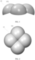
- the focusing component 13 includes at least two curved surface structural portions 131 sequentially connected adjacent to each other (for example, the focusing component 13 as shown in FIG. 1 and FIG. 2 includes four curved surface structural portions 131 sequentially connected adjacent to each other).
- the focusing component 13 is rotationally symmetric about a central axis of the focusing component, and an angle is formed between a plane in which the bottom of any one of the curved surface structural portions 131 is located and a plane perpendicular to the central axis of the focusing component 13.
- the at least two curved surface structural portions 131 sequentially connected adjacent to each other are integrally formed.
- each curved surface structural portion 131 corresponds to one focusing point.
- At least two pyroelectric infrared sensors (not shown in FIG. 1 and FIG. 2 ) are respectively disposed at respective focusing points, and the focusing component 13 is configured to focus external infrared signals onto respective pyroelectric infrared sensors.
- the at least two pyroelectric infrared sensors are configured to convert changes in the infrared signals into voltage signals when any one of the pyroelectric infrared sensors detects the changes in the infrared signals, and then to control a switch status of a lighting fixture by using the voltage signals.
- the positions of the respective focusing points of the focusing component 13 are determined, and the respective pyroelectric infrared sensors are mounted on the respective focusing points, so that the respective pyroelectric infrared sensors and the central axis of the focusing component 13 also form a certain angle, and then overlapping regions are formed between the detection regions of the pyroelectric infrared sensors.
- the detection points of the pyroelectric infrared sensors are more densely distributed in the respective overlapping regions, and the pyroelectric infrared sensors can sense a small amplitude of motion in the detection regions, effectively improving the sensing sensitivity of the pyroelectric infrared sensors.
- the focusing component 13 is further configured to divide the detection regions detectable by the at least two pyroelectric infrared sensors into a plurality of visible regions and a plurality of blind regions, wherein the plurality of visible regions and the plurality of blind regions are alternately arranged, so that in a case where there is a moving object in the detection regions, the infrared signals generated by the moving object are continuously switched between the plurality of visible regions and the plurality of blind regions to generate the changes in the infrared signals.
- the angle formed between the plane in which the bottom of any one of the curved surface structural portions 131 is located and the plane perpendicular to the central axis of the focusing component 13 is greater than 0 degrees and less than 45 degrees, or is greater than -45 degrees and less than 0 degrees.
- an angle of 6.6 degrees or -6.6 degrees can be preferred.
- the pyroelectric infrared sensors 12 located at the respective focusing points of the focusing component 13 have a better sensitivity to the infrared rays.
- the curved surface structural portions 131 may be a plurality of convex lenses sequentially connected adjacent to each other, or may be a plurality of Fresnel lenses sequentially connected adjacent to each other.
- the specific type of the lens adopted by the curved surface structural portions 131 is not limited in the embodiment of the present disclosure.
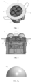
- the at least two curved surface structural portions 131 sequentially connected adjacent to each other included in the focusing component 13 in FIG. 1 and FIG. 2 can further be replaced with at least two curved surface structural portions 111 (for example, four curved surface structural portions 111 are included in FIG. 3 and FIG. 4 ) included in the focusing component 11 as shown in FIG. 3 and FIG. 4 .
- the shape of each of the curved surface structural portions 111 is specifically referred to in the schematic diagrams of the curved surface structural portions 111 at different angles as shown in FIG. 5a and FIG. 5b . The embodiment will be described in detail below.
- the focusing component 11 of the pyroelectric infrared sensor based lighting control device 1 includes at least two curved surface structural portions 111 circumferentially arranged around the central axis of the focusing component 11, and the focusing component 11 is rotationally symmetric about its central axis. An angle is formed between a plane in which the bottom of any one of the curved surface structural portions 111 is located and a plane perpendicular to the central axis of the focusing component 11.
- each curved surface structural portion 111 is a hemispherical structure.
- each of the curved surface structural portions 111 corresponds to one focusing point.
- the at least two pyroelectric infrared sensors 12 are respectively disposed at the respective focusing points, and the focusing component 11 is configured to focus external infrared signals onto the respective pyroelectric infrared sensors 12.
- the at least two pyroelectric infrared sensors 12 are configured to convert changes in the infrared signals into voltage signals when any one of the pyroelectric infrared sensors 12 detects the changes in the infrared signals, and then to control the switch status of the lighting fixture by using the voltage signals.
- the curved surface structural portions 111 can further be in another structural form, which is not specifically limited in the embodiment of the present disclosure.
- the curved surface structural portions 111 may be a plurality of convex lenses sequentially connected adjacent to each other, or may be a plurality of Fresnel lenses sequentially connected adjacent to each other.
- the specific type of the lens adopted by the curved surface structural portions 111 is not limited in the embodiment of the present disclosure.
- the Fresnel lens was invented by French physicist FRESNEL, and was pressed using an electroplating mold process and PE (polyethylene) material.
- the thickness of the lens of the Fresnel lens can generally be 0.5mm, and a circle of concentric circles from small to large, shallow to deep are recorded on the surface from the center to the periphery, and the cross-section looks like a sawtooth. If the ring lines composed of concentric circles are dense, the Fresnel lens has a large sensing angle and a far focal distance. If the ring lines are recorded deeply, the Fresnel lens has a far sensing distance and a close focal distance. The closer the infrared rays are to the ring lines, the more concentrated the light passing through the Fresnel lens is and the stronger the rays are.
- the circular lines on a same line of the Fresnel lens can form a vertical sensing region, and a horizontal sensing segment is formed between each of the circular lines.
- the fewer segments there are the lower the sensing sensitivity is, and only a larger movement of the human body can be sensed.
- the blind regions are formed between the respective vertical sensing regions of the Fresnel lens and between the respective horizontal sensing segments. But the concentric circles of the different sensing regions are interlaced, thus reducing the blind regions between the respective segments. Because the Fresnel lens is restricted by the angle of view of the infrared probe, the vertical and horizontal sensing angles are limited, and the area of the lens is also limited.
- the Fresnel lens can be divided into rectangular, square and circular shapes in appearance, and can be divided into single-region multi-segment, double-region multi-segment, multi-region multi-segment in function.
- the Fresnel lens there are two main functions of the Fresnel lens.
- One function is to achieve focusing, that is, the infrared signals can be refracted or reflected onto the pyroelectric infrared sensor, and the other function is to divide the detection regions of the pyroelectric infrared sensor into a plurality of visible regions and a plurality of blind regions.
- Each type of the Fresnel lens has a focusing point, and only the pyroelectric infrared sensor is placed at the focusing points to achieve the best focusing effect, thereby causing the sensitivity of the pyroelectric infrared sensor based lighting control device to be highest.
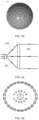
- the pyroelectric infrared sensor 101 is mounted on the focusing point of the Fresnel lens 102, and the external infrared signals (the infrared rays 103) are refracted onto the pyroelectric infrared sensor 101 through the Fresnel lens 102.
- FIG. 6b is a schematic diagram of the range of the pyroelectric infrared sensor horizontally sensing the infrared signals
- FIG. 6c is a schematic diagram of the range of the pyroelectric infrared sensor vertically sensing the infrared signals, and the vertical sensing range as shown in FIG. 6c is 10 meters.
- the focusing component 11 including four curved surface structural portions 111 arranged in a circumferential array around its central axis is an example to introduce the influence degree of different parameters on the sensitivity of the pyroelectric infrared sensor based lighting control device.
- Parameter 1 an offset distance between the curved surface structural portions.
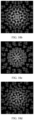
- FIG. 7a is a schematic diagram of an array of four curved surface structural portions 111 of the focusing component 11, and FIG. 7b is a sensing density map of the pyroelectric infrared sensors (not shown in FIG. 7a ) mounted on the focusing points of the respective curved surface structural portions 111 as shown in FIG. 7a to the infrared rays.
- FIG. 7c is a schematic diagram of the array after the horizontal distance between the respective curved surface structural portions 111 is increased by 10 mm on the basis of the array structure of the four curved surface structural portions 111 as shown in FIG. 7a
- FIG. 7d is a sensing density map of the pyroelectric infrared sensors (not shown in FIG. 7c ) mounted on the focusing points of the respective curved surface structural portions 111 as shown in FIG. 7c to the infrared rays.
- FIG. 7e is a schematic diagram of the array after the horizontal distance between the respective curved surface structural portions 111 is increased by 100 mm on the basis of the array structure of the four curved surface structural portions 111 as shown in FIG. 7a
- FIG. 7f is a sensing density map of the pyroelectric infrared sensors (not shown in FIG. 7e ) mounted on the focusing points of the respective curved surface structural portions 111 as shown in FIG. 7e to the infrared rays.
- Parameter 2 an offset angle between the curved surface structural portions.
- the angle between the plane perpendicular to the central axis of the focusing component 11 and the plane in which the bottom of any one of the curved surface structural portions 111 is located is 4.6 degrees, 6.6 degrees and 31 degrees, respectively.
- the contents as shown in FIGs. 8d to 8f are sensing density maps of the pyroelectric infrared sensors (not shown in FIGs. 8a to 8c ) mounted on the focusing points of the respective curved surface structural portions 111 as shown in FIGs. 8a to 8c to the infrared rays, respectively.
- Parameter three an offset direction of the curved surface structural portions.
- the angle between the plane perpendicular to the central axis of the focusing component 11 and the plane in which the bottom of any one of the curved surface structural portions 111 is located is -4.6 degrees, degree, degrees and - 31 degrees, respectively, and the offset directions of the angles in FIGs. 9a to 9c are opposite to those of the angles in FIGs. 8a to 8c .
- the contents as shown in FIGs. 9d to 9f are sensing density maps of the pyroelectric infrared sensors (not shown in FIG. 9a, FIG. 9b and FIG. 9c ) mounted on the focusing points of the respective curved surface structural portions 111 as shown in FIGS. 9a to 9c to the infrared rays, respectively.
- Parameter 4 a position of the chips of the pyroelectric infrared sensor with respect to the focusing points of the curved surface structural portions (selecting the pyroelectric infrared sensor with 2 chips)
- the angle between the plane perpendicular to the central axis of the focusing component and the plane in which the bottom of the respective curved surface structural portion is located is 4.6 degrees and 6.6 degrees, respectively
- the sensing density maps of the pyroelectric infrared sensor to the infrared rays are shown in FIG. 10a and FIG. 10b , respectively.
- the sensing density maps of the pyroelectric infrared sensor to the infrared rays are shown in FIG. 10c and FIG. 10d , respectively.
- Parameter 5 the amount of chips of the pyroelectric infrared sensor.
- the angle between the plane perpendicular to the central axis of the focusing component and the plane in which the bottom of the respective curved surface structural portion is located is 4.6 degrees and 6.6 degrees, respectively.
- the sensing density maps of the pyroelectric infrared sensor to the infrared rays are shown in FIGs. 11a and 11b , respectively.
- the sensing density maps of the pyroelectric infrared sensor to the infrared rays are shown in FIGs. 11c and 11d , respectively.
- the offset distance between the curved surface structural portions, the offset direction of the curved surface structural portions, and the position of the chips of the pyroelectric infrared sensor with respect to the focusing points of the curved surface structural portions J 2. have no great influence on the sensing density of the pyroelectric infrared sensor to the infrared rays, that is, there is no great influence on the sensitivity of the pyroelectric infrared sensor based lighting control device.
- the offset angle between the curved surface structural portions and the amount of the chips of the pyroelectric infrared sensor have great influence on the sensing density of the pyroelectric infrared sensor to the infrared rays, that is, there is great influence on the sensitivity of the lighting control device based pyroelectric infrared sensor.
- the angle between the plane perpendicular to the central axis of the focusing component and the plane in which the bottom of the respective curved surface structural portion is located is constant, the more chips of the pyroelectric infrared sensor there are, the larger the sensing density of the pyroelectric infrared sensors to the infrared rays is.
- the pyroelectric infrared sensor based lighting control system 2 includes a lighting fixture 21 and the pyroelectric infrared sensor based lighting control device 22 composed of the focusing component 13 as shown in FIG. 1 and FIG. 2 .
- the pyroelectric infrared sensors (not shown in FIG. 12 ) in the pyroelectric infrared sensor based lighting control device 22 are electrically connected to the lighting fixture 21, and the pyroelectric infrared sensors are configured to convert changes in the infrared signals into voltage signals when detecting the changes in the infrared signals, and to control the switch status of the lighting fixture 21 by using the voltage signals.
- the pyroelectric infrared sensors detect the changes in the infrared signals and convert the changes in the infrared signals into the voltage signals
- the pyroelectric infrared sensors control the lighting fixture 21 to be powered with the voltage signals to realize switching-on of the lighting fixture 21.
- the pyroelectric infrared sensor based lighting control device can further be the pyroelectric infrared sensor based lighting control device 1 as shown in FIG. 3 and FIG. 4 .
Landscapes
- Physics & Mathematics (AREA)
- General Physics & Mathematics (AREA)
- Spectroscopy & Molecular Physics (AREA)
- Engineering & Computer Science (AREA)
- Power Engineering (AREA)
- Optics & Photonics (AREA)
- General Engineering & Computer Science (AREA)
- Photometry And Measurement Of Optical Pulse Characteristics (AREA)
- Circuit Arrangement For Electric Light Sources In General (AREA)
Claims (7)
- Auf pyroelektrischem Infrarotsensor basierende Beleuchtungssteuerungsvorrichtung (1, 22), die eine Fokussierkomponente (11, 13) und mindestens zwei pyroelektrische Infrarot-Sensoren (12) aufweist,wobei die Fokussierkomponente (11, 13) mindestens zwei Strukturabschnitte (111, 131) mit gebogener Oberfläche aufweist, die der Reihe nach angrenzend aneinander verbunden sind, wobei die Fokussierkomponente (11, 13) rotationssymmetrisch um eine Mittelachse der Fokussierkomponente verläuft, und wobei ein Winkel zwischen einer Ebene, in der sich die Unterseite eines der Strukturabschnitte (111, 131) mit gebogener Oberfläche befindet, und einer Ebene ausgebildet ist, die senkrecht zu der Mittelachse der Fokussierkomponente (11, 13) ist;wobei die pyroelektrischen Infrarotsensoren (12) und die Mittelachse der Fokussierkomponente (11, 13) einen Winkel definieren und Überlappungsbereiche zwischen Detektionsbereichen der pyroelektrischen Infrarotsensoren (12) gebildet werden;wobei jeder der Strukturabschnitte (111, 131) mit gebogener Oberfläche einem Fokussierpunkt entspricht, wobei die mindestens zwei pyroelektrischen Infrarotsensoren (12) jeweils an entsprechenden Fokussierpunkten angeordnet sind, und wobei die Fokussierkomponente (11, 13) dazu ausgebildet ist, externe Infrarotsignale auf entsprechende pyroelektrische Infrarotsensoren (12) zu fokussieren; undwobei die mindestens zwei pyroelektrischen Infrarotsensoren (12) dazu ausgebildet sind, Änderungen in den Infrarotsignalen in Spannungssignale umzuwandeln, wenn einer der pyroelektrischen Infrarotsensoren (12) die Änderungen in den Infrarotsignalen detektiert, und anschießend einen Schaltzustand einer Leuchte (21) unter Verwendung der Spannungssignale zu steuern,dadurch gekennzeichnet, dass der Winkel, der zwischen der Ebene, in der sich die Unterseite eines der Strukturabschnitte (111, 131) mit gebogener Oberfläche befindet, und der Ebene ausgebildet ist, die senkrecht zu der Mittelachse der Fokussierkomponente (11, 13) ist, größer als 0 Grad und kleiner als 45 Grad ist, oder größer als -45 Grad und kleiner als 0 Grad ist.
- Vorrichtung nach Anspruch 1, wobei die Fokussierkomponente (11, 13) Detektionsbereiche, die von den mindestens zwei pyroelektrischen Infrarotsensoren (12) detektiert werden können, in eine Vielzahl von sichtbaren Bereichen und eine Vielzahl von blinden Bereichen unterteilt, wobei die Vielzahl von sichtbaren Bereichen und die Vielzahl von blinden Bereich abwechselnd angeordnet sind, so dass in einem Fall, in dem sich ein bewegliches Objekt in den Detektionsbereichen befindet, die von dem beweglichen Objekt erzeugten Infrarotsignale kontinuierlich zwischen der Vielzahl von sichtbaren Bereichen und der Vielzahl von blinden Bereichen wechseln, um die Änderungen in den Infrarotsignalen zu erzeugen.
- Vorrichtung nach Anspruch 1 oder Anspruch 2, wobei die mindestens zwei Strukturabschnitte (111, 131) mit gebogener Oberfläche, die der Reihe nach angrenzend aneinander verbunden sind, einstückig ausgebildet sind.
- Vorrichtung nach Anspruch 1 oder Anspruch 2, wobei die Strukturabschnitte (111, 131) mit gebogener Oberfläche eine Vielzahl von konvexen Linsen aufweisen, die der Reihe nach angrenzend aneinander verbunden sind, oder eine Vielzahl von Fresnel-Linsen (102) aufweisen, die der Reihe nach angrenzend aneinander verbunden sind.
- Vorrichtung nach Anspruch 1 oder Anspruch 2, wobei der Winkel, der zwischen der Ebene, in der sich die Unterseite eines der Strukturabschnitte (111, 131) mit gebogener Oberfläche befindet, und der Ebene ausgebildet ist, die senkrecht zu der Mittelachse der Fokussierkomponente (11, 13) ist, 6,6 Grad oder -6,6 Grad beträgt.
- Auf pyroelektrischem Infrarotsensor basierendes Beleuchtungssteuerungssystem, das aufweist:eine Leuchte (21) und die auf pyroelektrischem Infrarotsensor basierende Beleuchtungssteuerungsvorrichtung (1, 22) nach einem der Ansprüche 1 bis 5,wobei die pyroelektrischen Infrarotsensoren (12) in der auf pyroelektrischem Infrarotsensor basierenden Beleuchtungssteuerungsvorrichtung (1, 22) elektrisch mit der Leuchte (21) verbunden sind, und wobei die pyroelektrischen Infrarotsensoren (12) dazu ausgebildet sind, die Änderungen in den Infrarotsignalen in Spannungssignale umzuwandeln, wenn die Änderungen in den Infrarotsignalen detektiert werden, und einen Schaltzustand der Leuchte (21) unter Verwendung der Spannungssignale zu steuern.
- System nach Anspruch 6, wobei, wenn die pyroelektrischen Infrarotsensoren (12) die Änderungen in den Infrarotsignalen detektieren und die Änderungen in den Infrarotsignalen in Spannungssignale umwandeln, die pyroelektrischen Infrarotsensoren die Leuchte (21) so steuern, dass sie unter Verwendung der Spannungssignale mit Strom versorgt wird, um das Einschalten der Leuchte (21) zu realisieren.
Applications Claiming Priority (3)
| Application Number | Priority Date | Filing Date | Title |
|---|---|---|---|
| CN201710138293.3A CN106879142B (zh) | 2017-03-09 | 2017-03-09 | 一种基于热释电红外传感器的照明控制装置及系统 |
| CN201720226293.4U CN206790747U (zh) | 2017-03-09 | 2017-03-09 | 一种基于热释电红外传感器的照明控制装置及系统 |
| PCT/CN2018/072464 WO2018161724A1 (zh) | 2017-03-09 | 2018-01-12 | 一种基于热释电红外传感器的照明控制装置及系统 |
Publications (3)
| Publication Number | Publication Date |
|---|---|
| EP3576500A1 EP3576500A1 (de) | 2019-12-04 |
| EP3576500A4 EP3576500A4 (de) | 2020-03-04 |
| EP3576500B1 true EP3576500B1 (de) | 2024-10-16 |
Family
ID=63447293
Family Applications (1)
| Application Number | Title | Priority Date | Filing Date |
|---|---|---|---|
| EP18764031.3A Active EP3576500B1 (de) | 2017-03-09 | 2018-01-12 | Auf pyroelektrischem infrarotsensor basierende beleuchtungssteuerungsvorrichtung und system |
Country Status (3)
| Country | Link |
|---|---|
| US (1) | US10980095B2 (de) |
| EP (1) | EP3576500B1 (de) |
| WO (1) | WO2018161724A1 (de) |
Families Citing this family (1)
| Publication number | Priority date | Publication date | Assignee | Title |
|---|---|---|---|---|
| CN110967118B (zh) * | 2019-11-26 | 2021-09-28 | 博立码杰通讯(深圳)有限公司 | 菲涅尔透镜单元感应装置 |
Citations (1)
| Publication number | Priority date | Publication date | Assignee | Title |
|---|---|---|---|---|
| US20100260494A1 (en) * | 2009-02-23 | 2010-10-14 | Gary Edwin Sutton | Curvilinear sensor system |
Family Cites Families (25)
| Publication number | Priority date | Publication date | Assignee | Title |
|---|---|---|---|---|
| DE4314574C2 (de) * | 1993-04-29 | 1997-04-10 | Leica Lithographie Systeme Jen | Verfahren zur Herstellung einer Stufenlinse vom fresnelschen Typ |
| US6124974A (en) * | 1996-01-26 | 2000-09-26 | Proxemics | Lenslet array systems and methods |
| KR0176625B1 (ko) * | 1996-11-05 | 1999-04-01 | 삼성전자주식회사 | 적외선 물체검출장치 |
| DE10134565A1 (de) * | 2001-07-16 | 2003-02-06 | Luxmate Controls Gmbh Dornbirn | Bewegungssensor |
| GB2470128B (en) * | 2005-03-21 | 2011-05-18 | Visonic Ltd | Passive infra-red detectors |
| WO2006100672A2 (en) * | 2005-03-21 | 2006-09-28 | Visonic Ltd. | Passive infra-red detectors |
| US7459672B2 (en) * | 2007-01-19 | 2008-12-02 | Jenesis International, Inc. | Motion sensor with LED aiming aid |
| JPWO2010134255A1 (ja) * | 2009-05-18 | 2012-11-08 | 日本電気株式会社 | 赤外線センサ、電子機器、及び赤外線センサの製造方法 |
| CN101782661B (zh) * | 2009-09-22 | 2012-07-25 | 奥泰斯电子(东莞)有限公司 | 调节红外幕帘探测器灵敏度的方法及一种红外幕帘探测器 |
| US8569680B2 (en) * | 2009-12-21 | 2013-10-29 | University Of Wyoming | Hyperacuity from pre-blurred sampling of a multi-aperture visual sensor |
| US8373125B2 (en) * | 2010-08-30 | 2013-02-12 | Wenzhou Mtlc Electric Appliances Co., Ltd. | Occupancy detector switch |
| CN102590879B (zh) * | 2011-01-06 | 2015-01-07 | 博立码杰通讯(深圳)有限公司 | 一种菲涅尔透镜感应方法及系统 |
| GB2494850B (en) * | 2011-04-21 | 2013-09-11 | Cp Electronics Ltd | Passive infra red detector |
| DE102011076420A1 (de) * | 2011-05-24 | 2012-11-29 | Excelitas Technologies Gmbh & Co. Kg | Strahlungserfassungsvorrichtung, Schaltung |
| CN104422524B (zh) * | 2013-09-04 | 2018-04-27 | 海尔集团公司 | 一种基于红外热源探测的人体探测装置 |
| US9304043B2 (en) * | 2013-09-25 | 2016-04-05 | Intelliswitch S.A. De C.V. | Motion detection system |
| CN203933590U (zh) * | 2014-07-07 | 2014-11-05 | 刘东妮 | 定向红外感应开关 |
| CN104696920A (zh) * | 2015-03-13 | 2015-06-10 | 娲石水泥集团武汉万世科技有限公司 | 一种人体感应与手动智能控制开关 |
| US10161801B2 (en) * | 2016-01-19 | 2018-12-25 | Google Llc | Method and apparatus for detecting direction of motion with a passive sensor |
| CN106225934A (zh) * | 2016-08-15 | 2016-12-14 | 周红林 | 一种热释电传感器 |
| CN106132047B (zh) * | 2016-08-16 | 2019-02-22 | 东莞市思帝科安防技术有限公司 | 一种红外感应式夜灯的精准感应控制方法及夜灯 |
| CN106879142B (zh) * | 2017-03-09 | 2023-11-21 | 苏州欧普照明有限公司 | 一种基于热释电红外传感器的照明控制装置及系统 |
| CN206790747U (zh) * | 2017-03-09 | 2017-12-22 | 苏州欧普照明有限公司 | 一种基于热释电红外传感器的照明控制装置及系统 |
| JP6956379B2 (ja) * | 2017-08-31 | 2021-11-02 | パナソニックIpマネジメント株式会社 | 遮光板の取付構造、赤外線検出装置及びこれが備えている遮光板 |
| JP6945161B2 (ja) * | 2017-08-31 | 2021-10-06 | パナソニックIpマネジメント株式会社 | 赤外線検出装置 |
-
2018
- 2018-01-12 WO PCT/CN2018/072464 patent/WO2018161724A1/zh not_active Ceased
- 2018-01-12 EP EP18764031.3A patent/EP3576500B1/de active Active
-
2019
- 2019-09-09 US US16/564,715 patent/US10980095B2/en active Active
Patent Citations (1)
| Publication number | Priority date | Publication date | Assignee | Title |
|---|---|---|---|---|
| US20100260494A1 (en) * | 2009-02-23 | 2010-10-14 | Gary Edwin Sutton | Curvilinear sensor system |
Also Published As
| Publication number | Publication date |
|---|---|
| EP3576500A1 (de) | 2019-12-04 |
| US20190394856A1 (en) | 2019-12-26 |
| WO2018161724A1 (zh) | 2018-09-13 |
| US10980095B2 (en) | 2021-04-13 |
| EP3576500A4 (de) | 2020-03-04 |
Similar Documents
| Publication | Publication Date | Title |
|---|---|---|
| US9711018B2 (en) | Passive infra red detector | |
| US7075431B2 (en) | Logical pet immune intrusion detection apparatus and method | |
| US4930864A (en) | Domed segmented lens systems | |
| US20090302220A1 (en) | PIR Motion Sensor System | |
| JP6302100B2 (ja) | 放射線センサ | |
| US5442178A (en) | Cross-over field-of-view composite Fresnel lens for an infrared detection system | |
| CN107430030B (zh) | 人体探测装置 | |
| CN106879142B (zh) | 一种基于热释电红外传感器的照明控制装置及系统 | |
| CN101915947A (zh) | 一种菲涅尔透镜、探测器及安防系统 | |
| EP3576500B1 (de) | Auf pyroelektrischem infrarotsensor basierende beleuchtungssteuerungsvorrichtung und system | |
| US12510414B2 (en) | Optical element for a motion detector | |
| WO2019036655A1 (en) | FRESNEL LENS NETWORK WITH IMPROVED OPTICAL EFFICIENCY OUTSIDE | |
| TWI681173B (zh) | 紅外線檢測裝置 | |
| US20090102648A1 (en) | Motion detector | |
| TW201304526A (zh) | 可選擇不同偵測範圍之影像偵測模組 | |
| TWI667453B (zh) | 紅外線檢測裝置 | |
| CN206790747U (zh) | 一种基于热释电红外传感器的照明控制装置及系统 | |
| CN216526363U (zh) | 一种智能门铃用透镜结构 | |
| CN119756595B (zh) | 热释电透镜系统及目标检测物的检测方法 | |
| WO2025215776A1 (ja) | 人検知装置 | |
| JP2001235365A (ja) | 熱線センサ | |
| JP2756472B2 (ja) | 熱線式検出器 | |
| JPS61126435A (ja) | 熱線検知器 | |
| KR200408709Y1 (ko) | 감도를 극대화한 프레넬 렌즈구조 | |
| KR20180133036A (ko) | 동작감지 센서모듈 |
Legal Events
| Date | Code | Title | Description |
|---|---|---|---|
| STAA | Information on the status of an ep patent application or granted ep patent |
Free format text: STATUS: THE INTERNATIONAL PUBLICATION HAS BEEN MADE |
|
| PUAI | Public reference made under article 153(3) epc to a published international application that has entered the european phase |
Free format text: ORIGINAL CODE: 0009012 |
|
| STAA | Information on the status of an ep patent application or granted ep patent |
Free format text: STATUS: REQUEST FOR EXAMINATION WAS MADE |
|
| 17P | Request for examination filed |
Effective date: 20190828 |
|
| AK | Designated contracting states |
Kind code of ref document: A1 Designated state(s): AL AT BE BG CH CY CZ DE DK EE ES FI FR GB GR HR HU IE IS IT LI LT LU LV MC MK MT NL NO PL PT RO RS SE SI SK SM TR |
|
| AX | Request for extension of the european patent |
Extension state: BA ME |
|
| A4 | Supplementary search report drawn up and despatched |
Effective date: 20200131 |
|
| RIC1 | Information provided on ipc code assigned before grant |
Ipc: G01J 5/08 20060101ALI20200127BHEP Ipc: G02B 3/00 20060101AFI20200127BHEP Ipc: G01J 5/00 20060101ALI20200127BHEP Ipc: F21V 23/04 20060101ALI20200127BHEP Ipc: H05B 47/10 20200101ALI20200127BHEP Ipc: H05B 47/13 20200101ALI20200127BHEP |
|
| DAV | Request for validation of the european patent (deleted) | ||
| DAX | Request for extension of the european patent (deleted) | ||
| STAA | Information on the status of an ep patent application or granted ep patent |
Free format text: STATUS: EXAMINATION IS IN PROGRESS |
|
| 17Q | First examination report despatched |
Effective date: 20201005 |
|
| REG | Reference to a national code |
Ref country code: DE Ref legal event code: R079 Free format text: PREVIOUS MAIN CLASS: H05B0037020000 Ipc: G02B0003000000 Ref document number: 602018075510 Country of ref document: DE |
|
| GRAP | Despatch of communication of intention to grant a patent |
Free format text: ORIGINAL CODE: EPIDOSNIGR1 |
|
| STAA | Information on the status of an ep patent application or granted ep patent |
Free format text: STATUS: GRANT OF PATENT IS INTENDED |
|
| RIC1 | Information provided on ipc code assigned before grant |
Ipc: H05B 47/10 20200101ALI20240412BHEP Ipc: H05B 47/13 20200101ALI20240412BHEP Ipc: G01J 5/34 20060101ALI20240412BHEP Ipc: F21V 23/04 20060101ALI20240412BHEP Ipc: G01J 5/0806 20220101ALI20240412BHEP Ipc: G01J 5/00 20060101ALI20240412BHEP Ipc: G02B 3/00 20060101AFI20240412BHEP |
|
| INTG | Intention to grant announced |
Effective date: 20240507 |
|
| RIN1 | Information on inventor provided before grant (corrected) |
Inventor name: WU, GONGYU Inventor name: JIA, KUN Inventor name: XU, XINGXING Inventor name: LIU, CHAOBO |
|
| GRAS | Grant fee paid |
Free format text: ORIGINAL CODE: EPIDOSNIGR3 |
|
| GRAA | (expected) grant |
Free format text: ORIGINAL CODE: 0009210 |
|
| STAA | Information on the status of an ep patent application or granted ep patent |
Free format text: STATUS: THE PATENT HAS BEEN GRANTED |
|
| AK | Designated contracting states |
Kind code of ref document: B1 Designated state(s): AL AT BE BG CH CY CZ DE DK EE ES FI FR GB GR HR HU IE IS IT LI LT LU LV MC MK MT NL NO PL PT RO RS SE SI SK SM TR |
|
| REG | Reference to a national code |
Ref country code: GB Ref legal event code: FG4D |
|
| REG | Reference to a national code |
Ref country code: CH Ref legal event code: EP |
|
| REG | Reference to a national code |
Ref country code: IE Ref legal event code: FG4D |
|
| REG | Reference to a national code |
Ref country code: DE Ref legal event code: R096 Ref document number: 602018075510 Country of ref document: DE |
|
| REG | Reference to a national code |
Ref country code: NL Ref legal event code: FP |
|
| REG | Reference to a national code |
Ref country code: LT Ref legal event code: MG9D |
|
| REG | Reference to a national code |
Ref country code: AT Ref legal event code: MK05 Ref document number: 1733353 Country of ref document: AT Kind code of ref document: T Effective date: 20241016 |
|
| PG25 | Lapsed in a contracting state [announced via postgrant information from national office to epo] |
Ref country code: PT Free format text: LAPSE BECAUSE OF FAILURE TO SUBMIT A TRANSLATION OF THE DESCRIPTION OR TO PAY THE FEE WITHIN THE PRESCRIBED TIME-LIMIT Effective date: 20250217 Ref country code: HR Free format text: LAPSE BECAUSE OF FAILURE TO SUBMIT A TRANSLATION OF THE DESCRIPTION OR TO PAY THE FEE WITHIN THE PRESCRIBED TIME-LIMIT Effective date: 20241016 Ref country code: IS Free format text: LAPSE BECAUSE OF FAILURE TO SUBMIT A TRANSLATION OF THE DESCRIPTION OR TO PAY THE FEE WITHIN THE PRESCRIBED TIME-LIMIT Effective date: 20250216 |
|
| PG25 | Lapsed in a contracting state [announced via postgrant information from national office to epo] |
Ref country code: FI Free format text: LAPSE BECAUSE OF FAILURE TO SUBMIT A TRANSLATION OF THE DESCRIPTION OR TO PAY THE FEE WITHIN THE PRESCRIBED TIME-LIMIT Effective date: 20241016 |
|
| PG25 | Lapsed in a contracting state [announced via postgrant information from national office to epo] |
Ref country code: BG Free format text: LAPSE BECAUSE OF FAILURE TO SUBMIT A TRANSLATION OF THE DESCRIPTION OR TO PAY THE FEE WITHIN THE PRESCRIBED TIME-LIMIT Effective date: 20241016 |
|
| PG25 | Lapsed in a contracting state [announced via postgrant information from national office to epo] |
Ref country code: ES Free format text: LAPSE BECAUSE OF FAILURE TO SUBMIT A TRANSLATION OF THE DESCRIPTION OR TO PAY THE FEE WITHIN THE PRESCRIBED TIME-LIMIT Effective date: 20241016 |
|
| PG25 | Lapsed in a contracting state [announced via postgrant information from national office to epo] |
Ref country code: NO Free format text: LAPSE BECAUSE OF FAILURE TO SUBMIT A TRANSLATION OF THE DESCRIPTION OR TO PAY THE FEE WITHIN THE PRESCRIBED TIME-LIMIT Effective date: 20250116 |
|
| PG25 | Lapsed in a contracting state [announced via postgrant information from national office to epo] |
Ref country code: AT Free format text: LAPSE BECAUSE OF FAILURE TO SUBMIT A TRANSLATION OF THE DESCRIPTION OR TO PAY THE FEE WITHIN THE PRESCRIBED TIME-LIMIT Effective date: 20241016 Ref country code: LV Free format text: LAPSE BECAUSE OF FAILURE TO SUBMIT A TRANSLATION OF THE DESCRIPTION OR TO PAY THE FEE WITHIN THE PRESCRIBED TIME-LIMIT Effective date: 20241016 Ref country code: GR Free format text: LAPSE BECAUSE OF FAILURE TO SUBMIT A TRANSLATION OF THE DESCRIPTION OR TO PAY THE FEE WITHIN THE PRESCRIBED TIME-LIMIT Effective date: 20250117 |
|
| PG25 | Lapsed in a contracting state [announced via postgrant information from national office to epo] |
Ref country code: PL Free format text: LAPSE BECAUSE OF FAILURE TO SUBMIT A TRANSLATION OF THE DESCRIPTION OR TO PAY THE FEE WITHIN THE PRESCRIBED TIME-LIMIT Effective date: 20241016 |
|
| PG25 | Lapsed in a contracting state [announced via postgrant information from national office to epo] |
Ref country code: RS Free format text: LAPSE BECAUSE OF FAILURE TO SUBMIT A TRANSLATION OF THE DESCRIPTION OR TO PAY THE FEE WITHIN THE PRESCRIBED TIME-LIMIT Effective date: 20250116 |
|
| PG25 | Lapsed in a contracting state [announced via postgrant information from national office to epo] |
Ref country code: SM Free format text: LAPSE BECAUSE OF FAILURE TO SUBMIT A TRANSLATION OF THE DESCRIPTION OR TO PAY THE FEE WITHIN THE PRESCRIBED TIME-LIMIT Effective date: 20241016 |
|
| PG25 | Lapsed in a contracting state [announced via postgrant information from national office to epo] |
Ref country code: DK Free format text: LAPSE BECAUSE OF FAILURE TO SUBMIT A TRANSLATION OF THE DESCRIPTION OR TO PAY THE FEE WITHIN THE PRESCRIBED TIME-LIMIT Effective date: 20241016 |
|
| REG | Reference to a national code |
Ref country code: DE Ref legal event code: R097 Ref document number: 602018075510 Country of ref document: DE |
|
| PG25 | Lapsed in a contracting state [announced via postgrant information from national office to epo] |
Ref country code: EE Free format text: LAPSE BECAUSE OF FAILURE TO SUBMIT A TRANSLATION OF THE DESCRIPTION OR TO PAY THE FEE WITHIN THE PRESCRIBED TIME-LIMIT Effective date: 20241016 |
|
| PG25 | Lapsed in a contracting state [announced via postgrant information from national office to epo] |
Ref country code: RO Free format text: LAPSE BECAUSE OF FAILURE TO SUBMIT A TRANSLATION OF THE DESCRIPTION OR TO PAY THE FEE WITHIN THE PRESCRIBED TIME-LIMIT Effective date: 20241016 |
|
| PG25 | Lapsed in a contracting state [announced via postgrant information from national office to epo] |
Ref country code: SK Free format text: LAPSE BECAUSE OF FAILURE TO SUBMIT A TRANSLATION OF THE DESCRIPTION OR TO PAY THE FEE WITHIN THE PRESCRIBED TIME-LIMIT Effective date: 20241016 |
|
| PG25 | Lapsed in a contracting state [announced via postgrant information from national office to epo] |
Ref country code: CZ Free format text: LAPSE BECAUSE OF FAILURE TO SUBMIT A TRANSLATION OF THE DESCRIPTION OR TO PAY THE FEE WITHIN THE PRESCRIBED TIME-LIMIT Effective date: 20241016 |
|
| PG25 | Lapsed in a contracting state [announced via postgrant information from national office to epo] |
Ref country code: IT Free format text: LAPSE BECAUSE OF FAILURE TO SUBMIT A TRANSLATION OF THE DESCRIPTION OR TO PAY THE FEE WITHIN THE PRESCRIBED TIME-LIMIT Effective date: 20241016 |
|
| PLBE | No opposition filed within time limit |
Free format text: ORIGINAL CODE: 0009261 |
|
| STAA | Information on the status of an ep patent application or granted ep patent |
Free format text: STATUS: NO OPPOSITION FILED WITHIN TIME LIMIT |
|
| REG | Reference to a national code |
Ref country code: CH Ref legal event code: PL |
|
| PG25 | Lapsed in a contracting state [announced via postgrant information from national office to epo] |
Ref country code: SE Free format text: LAPSE BECAUSE OF FAILURE TO SUBMIT A TRANSLATION OF THE DESCRIPTION OR TO PAY THE FEE WITHIN THE PRESCRIBED TIME-LIMIT Effective date: 20241016 |
|
| PG25 | Lapsed in a contracting state [announced via postgrant information from national office to epo] |
Ref country code: MC Free format text: LAPSE BECAUSE OF FAILURE TO SUBMIT A TRANSLATION OF THE DESCRIPTION OR TO PAY THE FEE WITHIN THE PRESCRIBED TIME-LIMIT Effective date: 20241016 Ref country code: LU Free format text: LAPSE BECAUSE OF NON-PAYMENT OF DUE FEES Effective date: 20250112 |
|
| 26N | No opposition filed |
Effective date: 20250717 |
|
| PG25 | Lapsed in a contracting state [announced via postgrant information from national office to epo] |
Ref country code: CH Free format text: LAPSE BECAUSE OF NON-PAYMENT OF DUE FEES Effective date: 20250131 |
|
| PG25 | Lapsed in a contracting state [announced via postgrant information from national office to epo] |
Ref country code: IE Free format text: LAPSE BECAUSE OF NON-PAYMENT OF DUE FEES Effective date: 20250112 |
|
| PGFP | Annual fee paid to national office [announced via postgrant information from national office to epo] |
Ref country code: NL Payment date: 20260127 Year of fee payment: 9 |
|
| PGFP | Annual fee paid to national office [announced via postgrant information from national office to epo] |
Ref country code: GB Payment date: 20260127 Year of fee payment: 9 |
|
| PGFP | Annual fee paid to national office [announced via postgrant information from national office to epo] |
Ref country code: DE Payment date: 20260114 Year of fee payment: 9 |
|
| PGFP | Annual fee paid to national office [announced via postgrant information from national office to epo] |
Ref country code: BE Payment date: 20260119 Year of fee payment: 9 |
|
| PGFP | Annual fee paid to national office [announced via postgrant information from national office to epo] |
Ref country code: FR Payment date: 20260130 Year of fee payment: 9 |