EP3576519B1 - Steuereinheit für eine säge - Google Patents
Steuereinheit für eine säge Download PDFInfo
- Publication number
- EP3576519B1 EP3576519B1 EP18786761.9A EP18786761A EP3576519B1 EP 3576519 B1 EP3576519 B1 EP 3576519B1 EP 18786761 A EP18786761 A EP 18786761A EP 3576519 B1 EP3576519 B1 EP 3576519B1
- Authority
- EP
- European Patent Office
- Prior art keywords
- saw
- sawing
- pressure
- control unit
- hydraulic system
- Prior art date
- Legal status (The legal status is an assumption and is not a legal conclusion. Google has not performed a legal analysis and makes no representation as to the accuracy of the status listed.)
- Active
Links
Images
Classifications
-
- A—HUMAN NECESSITIES
- A01—AGRICULTURE; FORESTRY; ANIMAL HUSBANDRY; HUNTING; TRAPPING; FISHING
- A01G—HORTICULTURE; CULTIVATION OF VEGETABLES, FLOWERS, RICE, FRUIT, VINES, HOPS OR SEAWEED; FORESTRY; WATERING
- A01G23/00—Forestry
- A01G23/02—Transplanting, uprooting, felling or delimbing trees
- A01G23/08—Felling trees
- A01G23/083—Feller-delimbers
-
- A—HUMAN NECESSITIES
- A01—AGRICULTURE; FORESTRY; ANIMAL HUSBANDRY; HUNTING; TRAPPING; FISHING
- A01G—HORTICULTURE; CULTIVATION OF VEGETABLES, FLOWERS, RICE, FRUIT, VINES, HOPS OR SEAWEED; FORESTRY; WATERING
- A01G23/00—Forestry
- A01G23/02—Transplanting, uprooting, felling or delimbing trees
- A01G23/08—Felling trees
- A01G23/091—Sawing apparatus specially adapted for felling trees
-
- B—PERFORMING OPERATIONS; TRANSPORTING
- B27—WORKING OR PRESERVING WOOD OR SIMILAR MATERIAL; NAILING OR STAPLING MACHINES IN GENERAL
- B27B—SAWS FOR WOOD OR SIMILAR MATERIAL; COMPONENTS OR ACCESSORIES THEREFOR
- B27B17/00—Chain saws; Equipment therefor
- B27B17/02—Chain saws equipped with guide bar
Definitions
- the present invention relates to the field of systems for logging, and specifically a control unit for a saw in a sawing system for logging and a method for controlling a saw in a system for logging.
- a typical harvester for logging has a hydraulically powered chain saw for cutting trees.
- Different trees may have different densities, and the settings for one tree may not be optimal for another type of tree or the same type of tree at a different weather. For example, trees may be more difficult to saw during winter, when the wood is dry and hard, and easier to saw during spring when it is warmer and the trees have more sap.
- the harvesters may need to be configured for each type of tree, with respect to a number of parameters to optimize the efficiency.
- parameters may, for example, be saw chain speed, the type of wood, season, weather, chain quality, etc.
- the harvesters are configured once, and then used with the same parameters even if the environment changes. That is, most harvesters are used with a less than optimal configuration as the configuration may not be updated as often as needed.
- DE7032129 relates to a chain saw, wherein the chain of the saw blade is driven by a motor.
- the chain saw is driven as a function of the maximum allowed performance of the drive motor of the chain saw.
- WO 99/12410 A1 relates to a sawing machine comprising a saw chain and a hydraulic system including a sensor for measuring the hydraulic pressure.
- US20160146226 relates to a felling saw recovery control, wherein the associated motor should be operated at a target speed.
- An object of the present disclosure is therefore to mitigate at least some of the drawbacks described above.
- a control unit for controlling a saw in a harvester according to claim 1 and a method for controlling a saw in a harvester according to claim 10 are provided. Further embodiments are defined in the dependent claims.
- a control unit for controlling a saw in a harvester is provided.
- the saw is driven by a first hydraulic system and the saw is adapted to apply a saw pressure on a sawing area during sawing.
- the control unit comprises a sensor for measuring a pump pressure of the first hydraulic system.
- the control unit is configured to, in response to the pump pressure being above a first predetermined value, decrease the saw pressure applied by the saw during sawing, or, in response to the pump pressure being below a second predetermined value, increase the saw pressure applied by the saw during sawing, wherein the saw is operated by an actuator.
- the control unit is further adapted to control a pressure in a second hydraulic system driving the actuator.
- the control unit is configured to monitor a first pump pressure in the first hydraulic system during a sawing cycle and to control the actuator during a subsequent sawing cycle based on the first pump pressure.
- a method for controlling a saw in a harvester The saw is driven by a first hydraulic system and the saw is adapted to apply a saw pressure on a sawing area during sawing.
- the method comprises the step of obtaining a pump pressure from a pump of the first hydraulic system.
- the method further comprises to, in response to the pump pressure being above a first predetermined value, decrease the saw pressure applied by the saw during sawing, or, in response to the pump pressure being below a second predetermined value, increase the saw pressure applied by the saw during sawing.
- the method further comprises the steps of operating the saw by an actuator, and controlling a pressure in a second hydraulic system driving the actuator, monitoring a first pump pressure in the first hydraulic system during a sawing cycle, and controlling the actuator during a subsequent sawing cycle based on the first pump pressure.
- the control unit may control a pressure applied by the saw during its operation.
- the load applied on the saw by the material may depend on one or more sawing conditions. For example, the orientation of the saw during operation, the properties of the material to be sawed, the speed of the saw through the material to be sawed, etc., may influence the saw. It will be appreciated that an overload of the saw by applying too much pressure against the sawing area during operation may be avoided by the present invention, as the control unit may estimate the load applied on for the saw and decrease the pressure on the sawing area.
- control unit may control the operation of the saw in case the material (e.g. wood) is easier or harder to saw through than what the saw is configured for.
- the control unit may sense a pressure of the system that is lower (or higher) than a first (or second) predetermined value, and then increase (or decrease) the saw pressure of the saw on the sawing area.
- the present invention is highly beneficial in that the control unit may adapt the operation of the saw such that the sawing may be performed at an efficiency, or at least close to a maximum efficiency, without overloading the hydraulic system powering the saw.
- Sawing systems according to the prior art may try to keep the saw at a maximum speed for the saw.
- an operation of this kind may lead to power loss or malfunctions in the system, e.g. due to an overload of the hydraulics of the system.
- the purpose of the sawing systems of the prior art is to avoid that the motor is overloaded, being a completely different concept than that of the subject-matter of the present application of performing the control based on the pump pressure of the pump for not overloading the pump and/or keeping a maximum power of the pump during the operation of the saw.
- the energy source can deliver more power than the motor can handle.
- the saw may be operated even in a case of a relatively high load applied on the saw, if the pressure applied by the saw on the sawing area is adapted to accordingly, so that overloading the saw may be avoided.
- the effect of a driving hydraulic system is limited, and that the work applied by the saw affects the driving hydraulic system.
- a maximum sawing effect may be obtained while at the same time utilizing the hydraulic system at a maximum (or close to maximum) effect. This may be achieved by adapting the sawing pressure based on the pump pressure of the hydraulic system, i.e. adapting the sawing operation based on the load the pump is subjected to.
- the control unit may decrease or increase the pressure applied by the saw during sawing in accordance with the measured pump pressure.
- the decrease or increase of the pressure applied by the saw during sawing via the control unit may be implemented by monitoring a pump pressure of a pump driving a hydraulic system for powering the saw. In this way the load on the saw may be estimated and monitored.
- An increase in the pump pressure of the hydraulic system may indicate that the saw cannot be operated to a maximum extent and that the saw may be overloaded, or may be close to be overloaded.
- a decrease in the pump pressure may indicate that the saw may use more power without being overloaded. In this way, the sawing may be controlled to be operated at a maximum sawing speed or pressure, or at least close to a maximum sawing speed or pressure, without overloading the saw, and thereby the hydraulic system.
- the pressure may increase when the pressure applied by the saw is increased.
- the pump in the hydraulic system may be overloaded and may stop providing a flow in the hydraulic system. That is, when the saw is overloaded, the system driving the saw may also be overloaded.
- the control unit may control the pressure applied by the saw during sawing to stay close to a maximum sawing pressure and speed, without overloading the saw. In this way, the risk of the system being overloaded may be decreased, while utilizing the maximum effect of the hydraulic system.
- the pressure in the hydraulic system may be kept close to a pressure maximum. This provides a flow close to a maximum flow of the system that may be used during sawing to control the sawing speed of the saw. Having a close to maximum pressure and a close to maximum flow in the hydraulic system provides for utilizing the saw at a close to maximum performance, for example, by decreasing the sawing time. Utilizing the saw at a close to maximum performance may also decrease the risk of problems related to a slower operation of the saw, such as a risk for end splits, lowered performance (i.e. cut time), higher risk for operators of the saw, etc.
- the sawing In previous sawing systems for harvesters, the sawing needed to be programmed and controlled based on a specific set of parameters, such as the type of tree intended for sawing or the saw itself. In contrast, with this control unit, the optimal performance of the saw may be determined during sawing by monitoring the pump pressure. That is, the sawing may be adaptive to the current environment, and does not have to be based on a previously set configuration.
- the pressure applied by the saw may be adapted to the capacity of the hydraulic system, not just the saw, as the pressure applied by the saw is based on the pump pressure.
- saw may refer to any type of saw configured to be driven by a hydraulic system.
- the saw may be a chain saw driven by a flow of the hydraulic system, or a circular saw or a band saw.
- the saw may have a sawing member, i.e. a member or portion moving to saw through, for example, a tree.
- the saw may also have a sawing direction, i.e. a direction through, for example, the tree or item the saw is to saw through.
- the term "sawing area” is therefore to be interpreted as the area on which the saw saws with the sawing or rotating member through the item.
- the term "sawing speed” or “movement speed” of the saw is to be interpreted as the speed of the saw in the sawing direction, i.e. in a direction through the tree or log.
- a “saw pressure applied by the saw during sawing” is to be interpreted as related to the speed of the saw in the sawing direction, thereby applying a force or a pressure on the sawing area. Accordingly, it should be noted that by the expression “the saw being adapted to apply a saw pressure on a sawing area during sawing”, the saw is applied to a sawing area (e.g. of the wood) during sawing, the saw is accordingly and consequently adapted/configured to apply a saw pressure on this sawing area.
- hydraulic system may be interpreted as any hydraulic system suitable for driving or powering a saw. It may be a load-sensing hydraulic system. Typically, hydraulic systems comprise a pump and a hydraulic valve for determining or altering the current flow or pressure in the system.
- pump pressure it is meant the pressure created by the pump, i.e. the pressure downstream from the pump and upstream from the saw.
- the sensor may be any device or sensor capable of measuring or determine a pressure in the hydraulic system.
- predetermining value it is here meant a desired value and/or reference value.
- first predetermined value and the “second predetermined value” may be related.
- the second predetermined value may be within an interval from the first predetermined value. Alternatively, they may be equal.
- the control unit may determine that a measured value is higher or lower than the first predetermined value or the second predetermined values based on it being within an interval from the values.
- control unit is configured to decrease or increase the pressure applied by the saw during sawing
- substantially any unit(s), element(s), system(s) or the like e.g. comprising one or more actuator(s) and/or hydraulic systems, may be connected or coupled between the control unit and the saw.
- control unit may be configured to monitor the pump pressure in the first hydraulic system periodically or continuously.
- the monitoring may be performed by periodical measurements by the sensor at any suitable time interval. For continuous monitoring the time periods may be relatively small.
- control unit may relatively quickly adapt the pressure according to the monitored pump pressure. This may lead to a more efficient system as the pressure applied by the saw during sawing may be quickly adapted to changes in the environment that makes it easier or more difficult to saw. This further allows for improving the efficiency of the sawing while decreasing the risk for overloading the saw.
- control unit may be configured to output a control signal for controlling the saw pressure applied by the saw during sawing.
- control unit may be configured to output a control signal on a CAN-bus.
- control unit may control a pressure applied by the saw during sawing based on the control signal.
- the saw is inclinably arranged in the system, and the increase or decrease of the pressure applied by the saw during sawing is further based on an inclination of the saw.
- the saw may be inclined downwards during cutting of a tree trunk, and inclined upwards during felling of a tree. These types of harvesting may require different pressures applied by the saw on the sawing area.
- the system is intended for sawing of wood, and the increase or decrease of the pressure applied by the saw during sawing is further based on at least one property of the wood.
- the control unit may be configured to cut a specific type of wood or tree and adapt the pressure applied by the saw accordingly.
- the saw is operated by an actuator.
- the actuator is hydraulically driven and the control unit is adapted to control the actuator.
- the control unit may be further adapted to control a pressure in a second hydraulic system driving the actuator.
- the saw may continue to operate the sawing at maximum speed, and the pressure applied by the saw on a sawing area may be controlled by the actuator.
- control unit is configured to monitor a first pump pressure in the first hydraulic system during a sawing cycle and to control the actuator during a subsequent sawing cycle based on the first pump pressure.
- the controlling of a subsequent sawing cycle may be influenced by data from a previous sawing cycle. This may be beneficial as the sawing characteristics between sawing cycles may be similar.
- a subsequent sawing cycle may be performed for the same or a similar type of wood at the same or a similar temperature as the previous sawing cycle.
- the starting pressure applied by the saw on the sawing area for a subsequent sawing cycle may be determined based on the monitored sawing cycle.
- the sawing cycle may start at a pressure which is based on a previous sawing cycle, and thereby reduce the risk of any misconfiguration in the beginning of the sawing cycle. This may lead to a more efficient sawing cycle.
- control unit is comprised in a sawing system.
- the sawing system further comprises a saw, a first hydraulic system for driving the saw, an actuator for operating the saw, and a control unit according to any embodiment for controlling the actuator.
- the system may, for example, be configured to be arranged on a harvester or on another vehicle or machine where a sawing system is needed.
- the saw is a chain saw.
- the chain saw may comprise a saw sword and a rotating member comprising the chain, wherein the rotating member rotates around the saw sword.
- the rotating member may be driven by the hydraulic system.
- the pressure in the hydraulic system may increase when a pressure applied on the rotating member is increased, since the chain may move more slowly through the material that is being cut.
- the pressure in the hydraulic system may decrease when the pressure applied on the rotating member is decreased, as the chain may move faster through the material that is sawed.
- the system further comprises a second hydraulic system, wherein the actuator is driven by the second hydraulic system.
- the hydraulic system may cause movements of the actuator depending on a pressure from the hydraulic system to the actuator.
- the actuator may alternatively be driven by an electrical system or another type of system suitable for driving the actuator.
- the second hydraulic system is the same as the first hydraulic system.
- control unit may be relatively easily installed in an existing system.
- the second hydraulic system comprises a valve for controlling a pressure in the second hydraulic system.
- the pressure applied by the saw during sawing, as controlled by the actuator may be controlled by the control unit via the valve.
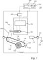
- Embodiments of the present inventive concept generally relate to a control unit 200 for controlling a saw 130 in a sawing system as shown in Figure 1 .
- the saw 130 is driven by a hydraulic system 100.
- Such hydraulic systems 100 generally comprise a pump 110, a tank 120 and a motor for driving the pump 170.
- the pump 110 may be a fixed displacement pump or a pump with a variable displacement.
- the motor may be any type of motor suitable for driving a pump, for example a combustion engine such as a diesel motor or an electrical motor.
- the saw 130 is in this example a chain saw.
- the saw 130 comprises a saw sword 132 and a rotating member 134.
- the rotating member 134 may be a saw chain.
- the rotating member 134 may be driven by the hydraulic system 100.
- the rotating member 134 has a rotational direction 138.
- the sawing system further comprises an actuator 156, a cylinder 152 and a second hydraulic system 150 for operating the saw 130.
- the second hydraulic system 150 may drive the cylinder 152 which acts on the actuator 156.
- the second hydraulic system 150, the cylinder 152 and the actuator 156 may be comprised in an actuator unit for operating the saw 130.
- the saw sword 132 has a sawing direction 136.
- the saw 130 may be a band saw, a circular saw or another type of saw suitable for cutting wood 140 and configured to be driven by a hydraulic system.
- the sawing system further comprises a control unit 200.
- the control unit 200 has a sensor 210 for measuring a pump pressure of the pump 110.
- the control unit 200 may also comprise a processing unit 220 to which the measured pump pressure may be communicated.
- the processing unit 220 may perform any calculations in the control unit 200.
- the control unit 200 may detect that the saw 130 or saw system 100 is working at a workload of the saw 130 which is close to, or even above, a maximum workload, based on the measured pump pressure being above a first predetermined level.
- the first predetermined level may, for example, be related to the maximum pump pressure for the pump 110. Alternatively, the first predetermined level may be related to other components in the sawing system or driven by the hydraulic system 100.
- the control unit 200 may output a control signal for decreasing the pressure applied by the saw 130 on the sawing area.
- the control unit 200 may alternatively determine that the saw 130 or the sawing system 100 is not working at a workload close to or above the first predetermined level based on the measured pump pressure being below a second predetermined level. In response to the measured pump pressure being below the second predetermined level, the processing unit 220 may output a control signal for increasing the pressure applied by the saw 130 on the sawing area.
- the control unit 200 may output the control signal indicating a pressure to be applied by the saw on a sawing area, or a change in the pressure to be applied, via a CAN-bus 160. It should be noted that any type of communication means may be used instead of the CAN-bus 160.
- the control unit 200 may periodically or continuously monitor the pump pressure.
- the sensor may measure the pressure every 0.1 seconds, 1 seconds, 2 second or at any other suitable time interval.
- the time period may be relatively small.
- the harvesting system 100 may further comprise a second hydraulic system 150 for operating the saw 130.
- the second hydraulic system 150 may comprise a control unit 154 and a hydraulic actuator 152 for operating the actuator 156.
- the actuator unit may receive the control signal sent from the control unit 200 via the CAN-bus 160.
- the actuator unit may control the movements of the saw 130 in the sawing direction 136 according to the control signal sent from the control unit. For example, the actuator unit may move the saw 130 faster in the sawing direction 136 to increase the pressure or move the saw 130 at slower in the sawing direction 136 to decrease the pressure.
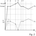
- Figure 2 shows two graphs, wherein Pa indicates a measured pump pressure over time and Pc indicates a value of the control signal sent by the control unit. More specifically, Pc indicates a pressure applied by the saw on a sawing area during sawing in response to the measured pressure Pa.
- both of Pa and Pc start at low values.
- the control unit may, in response to the pump pressure reaching maximum working level, set Pc at its preferred level, Pc Set.
- Pc Set the preferred level
- the control unit may determine a steering signal Pc indicating a decrease in the pressure applied by the saw.
- the control unit may determine another, lower steering signal Pc since the increase in pump pressure has not yet declined.
- the pump pressure starts to decline, and the control unit determines a steering signal Pc indicating an increase in the pressure applied by the saw during sawing.
- the control unit may determine to keep the steering signal Pc at the same level as before, as the measured pressure Pa has not recently changed.
- the measured pump pressure Pa is declining, which may be due to a change of the characteristics of the wood (tree/log) or another external event.
- the control unit may, in response to the measure pump pressure Pa declining, determine a steering signal Pc that indicates an increase in the pressure applied by the saw during sawing.
- the control unit 200 may determine the control signal based on the inclination of the saw 330.
- the inclination may be controlled by an operator operating the sawing system, or it may be pre-programmed based on a current sawing cycle.
- the control unit 200 may determine a control signal indicating a decrease in the pressure applied by the saw on the sawing are based on a downward inclination, which would commonly be used during cutting.
- the control unit 200 may determine a control signal indicating an increase in the pressure applied by the saw during sawing based in an upward tilt, which would commonly be used during felling.
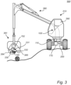
- FIG. 3 shows a schematic view of a sawing system 100 and a control unit 200 comprised in a vehicle 300.
- the vehicle 300 may be a harvester for logging, but also other applications for the sawing system 100 and the control unit 200 are envisaged.
- the vehicle 300 comprises a hydraulically driven sawing arm 380, a vehicle body 310 and a cab 390 at the vehicle body 310. An operator may drive the vehicle 300 and operate the arm 380 from within the cab 390.
- the vehicle 300 further comprises a sawing head 381 arranged at an end of the crane 380.
- the sawing head 381 comprises two holding portions 384, 385 and a saw 330.
- the saw 330 in this example, comprises a saw sword 332 and a rotating member 331. However, other types of saws may be used.
- the saw 330 is able to move between a folded state, wherein the saw 330 is arranged in the sawing head 381, and between an extended state, wherein a portion of the saw 330 has passed the holding portion 384 in the sawing direction.
- the holding portions 384, 385 may be arranged around a tree or log 140 to hold the tree 140 or log in place during sawing by the saw 330.
- the sawing system further comprises a pump 110 and an engine 170 for driving the pump 110, both arranged at the body 310 of the vehicle 300.
- the sawing system 100 further comprises an actuator 152 arranged at the sawing head 381 for operating the saw 330.
- the actuator 152 may be comprised in an actuator unit (not shown in Figure 3 ).
- the crane 380 may be operated by an operator such that the two holding portions 384, 385 are arranged around a tree 140.
- the saw may be arranged in the sawing head 381.
- the rotating member may rotate around the saw sword by means of the hydraulic system.
- the 330 saw may be operated by the actuator to apply a pressure against a sawing area on the tree 140.
- the control unit may monitor the pump pressure of the pump 110 and adjust the pressure applied on the sawing area of the tree as described above with reference to Figure 1 and Figure 2 .
Landscapes
- Life Sciences & Earth Sciences (AREA)
- Biodiversity & Conservation Biology (AREA)
- Ecology (AREA)
- Forests & Forestry (AREA)
- Environmental Sciences (AREA)
- Fluid-Pressure Circuits (AREA)
- Sawing (AREA)
Claims (10)
- Steuereinheit (200) zum Steuern einer Säge (130) in einer Erntemaschine, wobei die Säge durch ein erstes hydraulisches System (100) angetrieben wird und die Säge dazu ausgelegt ist, während des Sägens einen Sägedruck auf einen Sägebereich auszuüben, wobei die Steuereinheit Folgendes umfasst:einen Sensor (210) zum Messen eines Pumpendrucks des ersten hydraulischen Systems;und wobei die Steuereinheit für Folgendes konfiguriert ist:in Ansprechen darauf, dass der Pumpendruck über einem ersten vorbestimmten Wert liegt, Verringern des von der Säge während des Sägens ausgeübten Sägedrucks, oderin Ansprechen darauf, dass der Pumpendruck unter einem zweiten vorbestimmten Wert liegt, Erhöhen des von der Säge während des Sägens ausgeübten Sägedrucks,wobei die Säge durch einen Aktuator (156) betrieben wird, und die Steuereinheit ferner dazu ausgelegt ist, einen Druck in einem zweiten hydraulischen System (150) zu steuern, das den Aktuator antreibt,dadurch gekennzeichnet, dass die Steuereinheit dazu konfiguriert ist, einen ersten Pumpendruck während eines Sägezyklus in dem ersten hydraulischen System zu überwachen und den Aktuator während eines nachfolgenden Sägezyklus basierend auf dem ersten Pumpendruck zu steuern.
- Steuereinheit nach Anspruch 1, wobei die Steuereinheit dazu konfiguriert ist, den Pumpendruck in dem ersten hydraulischen System periodisch oder kontinuierlich zu überwachen.
- Steuereinheit nach einem der vorhergehenden Ansprüche, wobei die Steuereinheit dazu konfiguriert ist, ein Steuersignal zum Steuern des von der Säge während des Sägens ausgeübten Sägedrucks auszugeben.
- Steuereinheit nach einem der vorhergehenden Ansprüche, wobei die Säge neigbar im System angeordnet ist, und das Erhöhen oder das Verringern des von der Säge während des Sägens ausgeübten Sägedrucks ferner auf einer Neigung der Säge basiert.
- Steuereinheit nach einem der vorhergehenden Ansprüche, wobei das System zum Sägen von Holz bestimmt ist, und wobei das Erhöhen oder das Verringern des von der Säge während des Sägens ausgeübten Sägedrucks ferner auf mindestens einer Eigenschaft des Holzes basiert.
- Sägesystem, das Folgendes umfasst:eine Säge (330);ein erstes hydraulisches System (100) zum Antreiben der Säge;einen Aktuator (152) zum Betreiben der Säge;eine Steuereinheit (200) nach einem der vorhergehenden Ansprüche zum Steuern des Aktuators.
- System nach Anspruch 6, wobei die Säge eine Kettensäge ist.
- System nach Anspruch 6 oder 7, wobei das zweite hydraulische System das gleiche ist wie das erste hydraulische System.
- System nach Anspruch 6 oder 7, wobei das zweite hydraulische System ein Ventil zum Steuern eines Drucks in dem zweiten hydraulischen System umfasst.
- Verfahren zum Steuern einer Säge in einer Erntemaschine, wobei die Säge durch ein erstes hydraulisches System angetrieben wird und die Säge dazu ausgelegt ist, während des Sägens einen Sägedruck auf einen Sägebereich auszuüben, wobei das Verfahren die folgenden Schritte umfasst:Erhalten eines Pumpendrucks von einer Pumpe des ersten hydraulischen Systems; undin Ansprechen darauf, dass der Pumpendruck über einem vorbestimmten Wert liegt, Verringern des von der Säge während des Sägens ausgeübten Sägedrucks; oderin Ansprechen darauf, dass der Pumpendruck unter einem vorbestimmten Wert liegt, Erhöhen des von der Säge während des Sägens ausgeübten Sägedrucks,Betreiben der Säge durch einen Aktuator, und Steuern eines Drucks in einem zweiten hydraulischen System, das den Aktuator antreibt,Überwachen eines ersten Pumpendrucks in dem ersten hydraulischen System während eines Sägezyklus, und Steuern des Aktuators während eines nachfolgenden Sägezyklus basierend auf dem ersten Pumpendruck.
Applications Claiming Priority (2)
| Application Number | Priority Date | Filing Date | Title |
|---|---|---|---|
| SE1751295A SE541487C2 (en) | 2017-10-18 | 2017-10-18 | A control unit for controlling a saw, a sawing system and method therefore |
| PCT/EP2018/078000 WO2019076787A1 (en) | 2017-10-18 | 2018-10-15 | CONTROL UNIT OF A SAW |
Publications (3)
| Publication Number | Publication Date |
|---|---|
| EP3576519A1 EP3576519A1 (de) | 2019-12-11 |
| EP3576519C0 EP3576519C0 (de) | 2025-01-08 |
| EP3576519B1 true EP3576519B1 (de) | 2025-01-08 |
Family
ID=63862158
Family Applications (1)
| Application Number | Title | Priority Date | Filing Date |
|---|---|---|---|
| EP18786761.9A Active EP3576519B1 (de) | 2017-10-18 | 2018-10-15 | Steuereinheit für eine säge |
Country Status (4)
| Country | Link |
|---|---|
| EP (1) | EP3576519B1 (de) |
| ES (1) | ES3009741T3 (de) |
| SE (1) | SE541487C2 (de) |
| WO (1) | WO2019076787A1 (de) |
Families Citing this family (2)
| Publication number | Priority date | Publication date | Assignee | Title |
|---|---|---|---|---|
| SE548185C2 (en) * | 2024-09-12 | 2026-04-15 | Komatsu Forest Ab | Cut-to-length logging harvester vehicle and harvester head, and operating method for a cut-to-length logging harvester vehicle |
| AT528304B1 (de) * | 2024-10-22 | 2025-12-15 | Werner Steininger | Vorrichtung und verfahren zur erhöhung der betriebssicherheit eines fällkopfs |
Citations (1)
| Publication number | Priority date | Publication date | Assignee | Title |
|---|---|---|---|---|
| US20160010664A1 (en) * | 2014-07-08 | 2016-01-14 | Usinage G.N. Roy Inc. | Control system for a felling saw and method of control thereof |
Family Cites Families (14)
| Publication number | Priority date | Publication date | Assignee | Title |
|---|---|---|---|---|
| DE7032129U (de) * | 1970-08-28 | 1970-12-23 | Dolmar Maschinen Fabrik Gmbh | Ketten-schwenksaege. |
| US4942795A (en) * | 1988-06-02 | 1990-07-24 | Buehler Ltd. | Precision cutter with automated pressure control |
| SE9703236L (sv) * | 1997-09-09 | 1999-03-10 | Rolf Modd | Anordning för drift av ett bearbetningsaggregat |
| FI116266B (fi) * | 2000-05-10 | 2005-10-31 | Ponsse Oyj | Menetelmä ja järjestely katkaisusahan sahausnopeuden säätämiseksi |
| US6709315B1 (en) * | 2002-01-24 | 2004-03-23 | John D. Ward | Auto feed system for compressed propellant tools and pressure compensating valve therefore |
| FI122885B (fi) * | 2005-05-30 | 2012-08-31 | John Deere Forestry Oy | Metsäkoneen suorituskyvyn mittausjärjestelmä |
| WO2009144524A1 (en) * | 2008-05-30 | 2009-12-03 | Deere-Hitachi Specialty Products | A vehicular stored energy processor |
| US20120261032A1 (en) * | 2009-10-12 | 2012-10-18 | Deere And Company | Load sense and hydraulic pump management |
| WO2011046535A1 (en) * | 2009-10-12 | 2011-04-21 | Deere And Company | Load sense hydraulic pump alignment |
| JP5537734B2 (ja) * | 2010-06-28 | 2014-07-02 | ボルボ コンストラクション イクイップメント アーベー | 建設機械の油圧ポンプの流量制御システム |
| WO2012011615A1 (ko) * | 2010-07-19 | 2012-01-26 | 볼보 컨스트럭션 이큅먼트 에이비 | 건설기계의 유압펌프 제어시스템 |
| US20150289456A1 (en) * | 2014-04-11 | 2015-10-15 | Caterpillar Forest Products Inc. | Hydraulic arrangement for a delimber |
| US10221870B2 (en) * | 2014-11-26 | 2019-03-05 | Deere & Company | Felling saw recovery control |
| SE540505C2 (en) * | 2016-05-17 | 2018-09-25 | Log Max Ab | A tree harvesting machine, a tree harvesting monitoring system, a tree harvesting head, a method for controlling operation of a tree harvesting head and a method for monitoring operation of a tree harvesting machine |
-
2017
- 2017-10-18 SE SE1751295A patent/SE541487C2/en unknown
-
2018
- 2018-10-15 ES ES18786761T patent/ES3009741T3/es active Active
- 2018-10-15 WO PCT/EP2018/078000 patent/WO2019076787A1/en not_active Ceased
- 2018-10-15 EP EP18786761.9A patent/EP3576519B1/de active Active
Patent Citations (1)
| Publication number | Priority date | Publication date | Assignee | Title |
|---|---|---|---|---|
| US20160010664A1 (en) * | 2014-07-08 | 2016-01-14 | Usinage G.N. Roy Inc. | Control system for a felling saw and method of control thereof |
Also Published As
| Publication number | Publication date |
|---|---|
| WO2019076787A1 (en) | 2019-04-25 |
| EP3576519A1 (de) | 2019-12-11 |
| EP3576519C0 (de) | 2025-01-08 |
| SE1751295A1 (en) | 2019-04-19 |
| SE541487C2 (en) | 2019-10-15 |
| ES3009741T3 (en) | 2025-03-31 |
Similar Documents
| Publication | Publication Date | Title |
|---|---|---|
| CA2407690C (en) | Method and arrangement for adjusting feed rate of a crosscut saw | |
| US12514173B2 (en) | Tree processing system | |
| US11793125B2 (en) | Tree processing system | |
| US6041683A (en) | System for adjusting the rotation speed of a cross-cutting saw of a tree handling machine, especially grapple harvester | |
| EP3854482B1 (de) | Materialreduktionsmaschine mit dynamischer zuführungssteuerung | |
| FI127122B (fi) | Menetelmä ja järjestelmä puunkäsittelylaitteen käsittävän puomiston toimintojen ohjaamiseksi puun kaatotapahtuman yhteydessä ja vastaava metsäkone | |
| EP3812112B1 (de) | Hydrauliksystem zur steuerung einer sägevorrichtung | |
| WO2019076787A1 (en) | CONTROL UNIT OF A SAW | |
| JP2014511984A (ja) | カッティング装置用油圧システムおよび対応する方法 | |
| CA2893152A1 (en) | Felling saw recovery control | |
| CN119687073A (zh) | 一种用于伐木机的链锯自适应控制系统及方法 | |
| WO1999012410A1 (en) | A device for operating a machining apparatus | |
| WO2023242018A1 (en) | Tree shears and control method therefor | |
| CA2844181C (en) | A timber-working head and method of operation | |
| FI121587B (fi) | Menetelmä metsäkoneen harvesteripään toimintojen ohjaamiseksi ja metsäkone | |
| US20260007112A1 (en) | Arrangement, device, felling head and forestry vehicle with a lubrication system | |
| WO2023242019A1 (en) | Tree shears and control method therefor | |
| JP2015167509A (ja) | 林業機械 | |
| JP2016021943A (ja) | 林業機械 |
Legal Events
| Date | Code | Title | Description |
|---|---|---|---|
| STAA | Information on the status of an ep patent application or granted ep patent |
Free format text: STATUS: UNKNOWN |
|
| STAA | Information on the status of an ep patent application or granted ep patent |
Free format text: STATUS: THE INTERNATIONAL PUBLICATION HAS BEEN MADE |
|
| PUAI | Public reference made under article 153(3) epc to a published international application that has entered the european phase |
Free format text: ORIGINAL CODE: 0009012 |
|
| STAA | Information on the status of an ep patent application or granted ep patent |
Free format text: STATUS: REQUEST FOR EXAMINATION WAS MADE |
|
| 17P | Request for examination filed |
Effective date: 20190904 |
|
| AK | Designated contracting states |
Kind code of ref document: A1 Designated state(s): AL AT BE BG CH CY CZ DE DK EE ES FI FR GB GR HR HU IE IS IT LI LT LU LV MC MK MT NL NO PL PT RO RS SE SI SK SM TR |
|
| AX | Request for extension of the european patent |
Extension state: BA ME |
|
| DAV | Request for validation of the european patent (deleted) | ||
| DAX | Request for extension of the european patent (deleted) | ||
| STAA | Information on the status of an ep patent application or granted ep patent |
Free format text: STATUS: EXAMINATION IS IN PROGRESS |
|
| 17Q | First examination report despatched |
Effective date: 20220411 |
|
| GRAP | Despatch of communication of intention to grant a patent |
Free format text: ORIGINAL CODE: EPIDOSNIGR1 |
|
| STAA | Information on the status of an ep patent application or granted ep patent |
Free format text: STATUS: GRANT OF PATENT IS INTENDED |
|
| INTG | Intention to grant announced |
Effective date: 20240806 |
|
| GRAS | Grant fee paid |
Free format text: ORIGINAL CODE: EPIDOSNIGR3 |
|
| GRAA | (expected) grant |
Free format text: ORIGINAL CODE: 0009210 |
|
| STAA | Information on the status of an ep patent application or granted ep patent |
Free format text: STATUS: THE PATENT HAS BEEN GRANTED |
|
| AK | Designated contracting states |
Kind code of ref document: B1 Designated state(s): AL AT BE BG CH CY CZ DE DK EE ES FI FR GB GR HR HU IE IS IT LI LT LU LV MC MK MT NL NO PL PT RO RS SE SI SK SM TR |
|
| REG | Reference to a national code |
Ref country code: GB Ref legal event code: FG4D |
|
| REG | Reference to a national code |
Ref country code: CH Ref legal event code: EP |
|
| REG | Reference to a national code |
Ref country code: DE Ref legal event code: R096 Ref document number: 602018078369 Country of ref document: DE |
|
| REG | Reference to a national code |
Ref country code: IE Ref legal event code: FG4D |
|
| U01 | Request for unitary effect filed |
Effective date: 20250204 |
|
| U07 | Unitary effect registered |
Designated state(s): AT BE BG DE DK EE FI FR IT LT LU LV MT NL PT RO SE SI Effective date: 20250210 |
|
| REG | Reference to a national code |
Ref country code: ES Ref legal event code: FG2A Ref document number: 3009741 Country of ref document: ES Kind code of ref document: T3 Effective date: 20250331 |
|
| PG25 | Lapsed in a contracting state [announced via postgrant information from national office to epo] |
Ref country code: RS Free format text: LAPSE BECAUSE OF FAILURE TO SUBMIT A TRANSLATION OF THE DESCRIPTION OR TO PAY THE FEE WITHIN THE PRESCRIBED TIME-LIMIT Effective date: 20250408 |
|
| PG25 | Lapsed in a contracting state [announced via postgrant information from national office to epo] |
Ref country code: PL Free format text: LAPSE BECAUSE OF FAILURE TO SUBMIT A TRANSLATION OF THE DESCRIPTION OR TO PAY THE FEE WITHIN THE PRESCRIBED TIME-LIMIT Effective date: 20250108 |
|
| PG25 | Lapsed in a contracting state [announced via postgrant information from national office to epo] |
Ref country code: IS Free format text: LAPSE BECAUSE OF FAILURE TO SUBMIT A TRANSLATION OF THE DESCRIPTION OR TO PAY THE FEE WITHIN THE PRESCRIBED TIME-LIMIT Effective date: 20250508 |
|
| PG25 | Lapsed in a contracting state [announced via postgrant information from national office to epo] |
Ref country code: HR Free format text: LAPSE BECAUSE OF FAILURE TO SUBMIT A TRANSLATION OF THE DESCRIPTION OR TO PAY THE FEE WITHIN THE PRESCRIBED TIME-LIMIT Effective date: 20250108 |
|
| PG25 | Lapsed in a contracting state [announced via postgrant information from national office to epo] |
Ref country code: GR Free format text: LAPSE BECAUSE OF FAILURE TO SUBMIT A TRANSLATION OF THE DESCRIPTION OR TO PAY THE FEE WITHIN THE PRESCRIBED TIME-LIMIT Effective date: 20250409 |
|
| PG25 | Lapsed in a contracting state [announced via postgrant information from national office to epo] |
Ref country code: SM Free format text: LAPSE BECAUSE OF FAILURE TO SUBMIT A TRANSLATION OF THE DESCRIPTION OR TO PAY THE FEE WITHIN THE PRESCRIBED TIME-LIMIT Effective date: 20250108 |
|
| PG25 | Lapsed in a contracting state [announced via postgrant information from national office to epo] |
Ref country code: CZ Free format text: LAPSE BECAUSE OF FAILURE TO SUBMIT A TRANSLATION OF THE DESCRIPTION OR TO PAY THE FEE WITHIN THE PRESCRIBED TIME-LIMIT Effective date: 20250108 |
|
| PG25 | Lapsed in a contracting state [announced via postgrant information from national office to epo] |
Ref country code: SK Free format text: LAPSE BECAUSE OF FAILURE TO SUBMIT A TRANSLATION OF THE DESCRIPTION OR TO PAY THE FEE WITHIN THE PRESCRIBED TIME-LIMIT Effective date: 20250108 |
|
| U20 | Renewal fee for the european patent with unitary effect paid |
Year of fee payment: 8 Effective date: 20250930 |
|
| PLBE | No opposition filed within time limit |
Free format text: ORIGINAL CODE: 0009261 |
|
| STAA | Information on the status of an ep patent application or granted ep patent |
Free format text: STATUS: NO OPPOSITION FILED WITHIN TIME LIMIT |
|
| REG | Reference to a national code |
Ref country code: CH Ref legal event code: L10 Free format text: ST27 STATUS EVENT CODE: U-0-0-L10-L00 (AS PROVIDED BY THE NATIONAL OFFICE) Effective date: 20251119 |
|
| 26N | No opposition filed |
Effective date: 20251009 |
|
| PGFP | Annual fee paid to national office [announced via postgrant information from national office to epo] |
Ref country code: NO Payment date: 20251029 Year of fee payment: 8 |
|
| PGFP | Annual fee paid to national office [announced via postgrant information from national office to epo] |
Ref country code: ES Payment date: 20251231 Year of fee payment: 8 |
|
| REG | Reference to a national code |
Ref country code: CH Ref legal event code: H13 Free format text: ST27 STATUS EVENT CODE: U-0-0-H10-H13 (AS PROVIDED BY THE NATIONAL OFFICE) Effective date: 20260527 |
|
| GBPC | Gb: european patent ceased through non-payment of renewal fee |
Effective date: 20251015 |
|
| PG25 | Lapsed in a contracting state [announced via postgrant information from national office to epo] |
Ref country code: MC Free format text: LAPSE BECAUSE OF FAILURE TO SUBMIT A TRANSLATION OF THE DESCRIPTION OR TO PAY THE FEE WITHIN THE PRESCRIBED TIME-LIMIT Effective date: 20250108 |
|
| PG25 | Lapsed in a contracting state [announced via postgrant information from national office to epo] |
Ref country code: GB Free format text: LAPSE BECAUSE OF NON-PAYMENT OF DUE FEES Effective date: 20251015 |
|
| PG25 | Lapsed in a contracting state [announced via postgrant information from national office to epo] |
Ref country code: CH Free format text: LAPSE BECAUSE OF NON-PAYMENT OF DUE FEES Effective date: 20251031 |