EP3576587B1 - Toilette - Google Patents
Toilette Download PDFInfo
- Publication number
- EP3576587B1 EP3576587B1 EP18747808.6A EP18747808A EP3576587B1 EP 3576587 B1 EP3576587 B1 EP 3576587B1 EP 18747808 A EP18747808 A EP 18747808A EP 3576587 B1 EP3576587 B1 EP 3576587B1
- Authority
- EP
- European Patent Office
- Prior art keywords
- seat
- toilet
- pressure
- actuator
- sensor
- Prior art date
- Legal status (The legal status is an assumption and is not a legal conclusion. Google has not performed a legal analysis and makes no representation as to the accuracy of the status listed.)
- Active
Links
Images


Classifications
-
- A—HUMAN NECESSITIES
- A61—MEDICAL OR VETERINARY SCIENCE; HYGIENE
- A61G—TRANSPORT, PERSONAL CONVEYANCES, OR ACCOMMODATION SPECIALLY ADAPTED FOR PATIENTS OR DISABLED PERSONS; OPERATING TABLES OR CHAIRS; CHAIRS FOR DENTISTRY; FUNERAL DEVICES
- A61G5/00—Chairs or personal conveyances specially adapted for patients or disabled persons, e.g. wheelchairs
- A61G5/10—Parts, details or accessories
- A61G5/1002—Parts, details or accessories with toilet facilities
-
- A—HUMAN NECESSITIES
- A47—FURNITURE; DOMESTIC ARTICLES OR APPLIANCES; COFFEE MILLS; SPICE MILLS; SUCTION CLEANERS IN GENERAL
- A47K—SANITARY EQUIPMENT; ACCESSORIES THEREFOR, e.g. TOILET ACCESSORIES
- A47K11/00—Closets without flushing; Urinals without flushing; Chamber pots; Chairs with toilet conveniences or specially adapted for use with toilets
- A47K11/04—Room closets; Chairs with toilet conveniences or specially adapted for use with toilets, e.g. night chairs ; Closets for children, also with signalling means, e.g. with a music box, or the like
-
- A—HUMAN NECESSITIES
- A61—MEDICAL OR VETERINARY SCIENCE; HYGIENE
- A61G—TRANSPORT, PERSONAL CONVEYANCES, OR ACCOMMODATION SPECIALLY ADAPTED FOR PATIENTS OR DISABLED PERSONS; OPERATING TABLES OR CHAIRS; CHAIRS FOR DENTISTRY; FUNERAL DEVICES
- A61G5/00—Chairs or personal conveyances specially adapted for patients or disabled persons, e.g. wheelchairs
- A61G5/10—Parts, details or accessories
- A61G5/1056—Arrangements for adjusting the seat
-
- A—HUMAN NECESSITIES
- A61—MEDICAL OR VETERINARY SCIENCE; HYGIENE
- A61G—TRANSPORT, PERSONAL CONVEYANCES, OR ACCOMMODATION SPECIALLY ADAPTED FOR PATIENTS OR DISABLED PERSONS; OPERATING TABLES OR CHAIRS; CHAIRS FOR DENTISTRY; FUNERAL DEVICES
- A61G2203/00—General characteristics of devices
- A61G2203/30—General characteristics of devices characterised by sensor means
- A61G2203/34—General characteristics of devices characterised by sensor means for pressure
Definitions
- This invention relates to toilets generally, and is more specifically directed to a toilet that discourages users from exiting the toilet without assistance. Such a toilet is disclosed in the US2009144891 .
- a person using a toilet in a healthcare facility or nursing home, and who is a fall risk, is given privacy while using the toilet.
- the person is instructed to request assistance before attempting to exit the toilet.
- people are frequently embarrassed to ask for assistance, and attempt to exit the toilet without assistance.
- Such persons may be at risk of falling due to age, medical condition, or medications, as they transition from a seated to a standing position.
- the present invention is a toilet that inhibits an occupant from exiting the toilet, as further disclosed in the claims.
- Sensors positioned on the toilet detect the application of pressure on the toilet by an occupant that is consistent with an occupant attempting to exit the toilet, and/or movements of the occupant that are consistent with an occupant attempting to exit the toilet.
- the sensors cause an actuator to change the angle of the toilet seat, which inhibits exiting the toilet.
- the toilet may also be constructed to signal an attendant when actions by an occupant are consistent with actions indicating an attempt by the occupant to exit the toilet.
- the present invention is a toilet comprising one or more sensors that sense movements of an occupant that are indicative of a person attempting to exit a toilet.
- the sensors emit a signal that actuates changes in an angle of the seat of the toilet.
- an angle of the seat of the toilet changes from generally horizontal to an angle that is not horizontal.
- a top surface of the toilet changes from generally horizontal to an angle that is preferably not more than thirty degrees and more preferably not more than twenty two and a half (22 1 ⁇ 2°) degrees from horizontal, with the front of the toilet seat, or portion of the toilet seat closer to the front of the toilet seat, elevated relative to the rear of the toilet seat, that is, the seat is moved to incline from a rear portion of the seat to a front portion of the seat.
- the change in angle increases the effort required to exit the toilet, and inhibits a user from exiting from the toilet, particularly where the user is of advanced age, or has limited strength or mobility, due to medical conditions or medications.
- the actuator is positioned in the rear of the toilet, and the seat is moved to the inclined position by moving the rear of the seat downwardly.
- the actuator is positioned in the front of the device. The actuator moves the front of the seat upwardly so that the inclined position of the seat is accomplished by moving the front of the seat upwardly relative to the rear of the seat
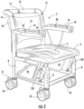
- a toilet similar to a portable toilet used in medical facilities and nursing homes is depicted.
- the toilet 2 has a seat 3, with an opening 4 in the seat that communicates with a receptacle for waste material.
- the seat is elevated to an appropriate height by a plurality of legs 8, such as four legs.
- Arms, such as the pair of arms 10, are spaced apart and are present on opposite sides of the toilet seat. The arms may extend upwardly from the toilet seat, providing an opening between the arms for access to the seat.
- the arms 10 may be connected to a back 12 that extends upwardly from a rear portion of the toilet.
- One or more sensors 14 are used that sense movement by an occupant that is consistent with a person attempting to exit the toilet. Such movements typically involve moving from a seated position to a standing position. For example, a person's back moving away from the back 12 of the toilet is an indication that the person may be attempting to stand. Typically, this movement also includes a person applying pressure to one of, or both of, the arms 10 of the toilet, so as to push themselves from a seated position to a standing position.
- the toilet seat has sensors 14 in the back 12 of the seat that emit a radio frequency signal from a sending and receiving unit that measures movement away from the back and senses the distance of the user's back from the back 12 of the toilet.
- sensors 14 Other sensor types that measure distance, such as distance measuring devices that use lasers, may be used as sensors 14.
- the back of the toilet seat is positioned lower than the front of the toilet seat to inhibit the person's attempt to exit or stand up.
- a signal may be emitted to an attendant as described herein anytime that the toilet seat moves due to actuation by a signal from a sensor.
- one or more of the sensors 14 sense motion.
- the motion sensors are calibrated to actuate the actuator due to more movement by the user that is more than normal shifting about while seated.
- one or more pressure sensors 18 are located in the arms of the device.
- a plurality of spaced apart pressure sensors may be used, since different users will apply pressure to the arms in different places while attempting to stand up or exit the toilet.
- the pressure sensors are calibrated so that when pressure that is significant enough to indicate a user's attempt to stand or exit the toilet, the toilet seat moves to an inclined position as described herein to inhibit such movement.
- pressure sensors 28 which may be load cells, are located in the arms of the device sense rearward pressure on the arms 10, as demonstrated by the arrow on the arm in Figure 1 .
- the pressure sensors 28 measure such rearward pressure and actuate the lowering of the rear of the toilet seat in response to the pressure.
- the pressure sensors are calibrated so that when pressure that is significant enough to indicate a user's attempt to stand or exit the toilet, the toilet seat inclines to inhibit such movement.
- the pressure sensors 28 are preferred to be used with pressure sensors 18, but may be used independently of each other.
- the dotted line and vertical arrow in Figure 1 demonstrate exemplary movement of the toilet seat 3.
- a change of the angle of the toilet seat 3 from substantially horizontal to an incline, with the rear of the toilet seat lower than the front of the toilet seat, or a portion of the toilet seat that is closer to the front, may be accomplished by hinging a portion of the toilet seat so that it pivots.
- the actuators 20, 120 may be an air or hydraulic cylinder that may be used to pull the rear of the toilet seat down, or push the front of the seat up in another embodiment, in response to movement of the user, and/or pressure applied to the arms of the toilet as described above.
- the actuators' normal position holds the seat and occupant in a generally horizontal position.
- the actuators 20, 120 may be an electrically powered actuator.
- An electric motor with rack and pinion gear may be used as an actuator to lower the seat.
- the electric motor may be powered by a battery, particularly where portability of the toilet is desired.
- two batteries 42, 44 provide power redundancy.
- the actuators 20, 120 may be extended to support the toilet seat 3 in a generally horizontal position under normal use, but upon receiving a signal from a motion sensor, pressure sensor or other sensor, or a combination, the actuator retracts so as to push the front of the seat upwardly.
- the toilet seat is repositioned at an angle, which is preferred to not to exceed thirty degrees from horizontal and is more preferred to not exceed twenty two and a half (22 1/2°) degrees from horizontal.
- the incline of the toilet seat will inhibit, although not necessarily prevent, a user from standing or exiting the toilet.
- lowering of the rear of toilet seat 3 may be terminated if the sensor or sensors that have initiated actuation of the actuators 20, 120 senses that movement by the user is terminated. For example, if pressure on the arms is terminated, or movement away from the seat back is terminated and the user moves his or her back against the seat back, movement of the seat may be terminated at less than full movement.
- the seat upon sensing that movement is terminated, the seat returns to its original position, or alternatively, only if the user's back is positioned against the seat back as sensed by sensors 14 does the seat return to its original position.
- the device is preferred to again lower the rear of the seat if movement is sensed.
- actuation of one or more of the sensors also actuates an alert provided to an attendant so that help is summoned to the toilet and to the user of the toilet.
- alert may be an audible or visual signal 40 provided at a central location, such as a nurse's station, or a signal that is provided to a mobile telephone or other receiving device.
- a call button 30 may be positioned on the device so that the user may intentionally press the button to seek assistance. Wireless communications may be used to alert an assistant.
- the actuator for the seat is actuated by a mechanical switch.
- a barrier such as crossbar 22, 122 is positioned between the arms at the front of the toilet.
- Figure 2 Figure 6 ;
- the barrier may be pivotally mounted 26 at one end of the barrier.
- two barriers or crossbars 102 are used, with one barrier pivotally mounted to each of the arms.
- a crossbar sensor senses movement of the barrier.
- the crossbar sensor 24 may be a switch that initiates actuation of the actuators 20, 120. Actuating the crossbar sensor by pushing against it could lock the crossbar from further movement, preventing the occupant from exiting the toilet.
- the actuator may be mounted to push or lift the back of the seat above the front of the seat in order to assist exiting the toilet.
- the maximum angle of the seat is limited to a maximum of about 30° from horizontal, and is more preferably limited to about 22 1/2°, from horizontal.
- Lifting the rear of the toilet seat 3 relative to the front is preferred to be actuated by a switch or other actuation device to which the user of the toilet does not have access while occupying the toilet. Actuation of this feature is preferred to be available only when an assistant is present. Actuation may be provided by a switch that communicates with the actuator or actuators 20, 120, such as a mechanical switch or a wireless remote communications device.
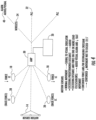
- FIG. 3 and Figure 4 demonstrate the interrelationship of the electromechanical features of the invention according to an embodiment of the invention.
- the motion or distance sensors 14, load cells 18, and crossbar sensor 24 communicate with a wireless transmitter that may include a signal amplifier. Communications may be via a local area wireless computer networking technology (Wi-Fi) connective devices, or devices that provide short range wireless communications, including but not limited to those communications devices operating at frequencies between 2402 and 2480 MHz, or 2400 and 2483.5 MHz, such as Bluetooth ® devices.
- the wireless transmitter 30 may be connected to a microcomputer 32 that actuates the actuators 20, 120. The wireless transmitter may also actuate an audible or visual signal, which is demonstrated by the call bell 36 in Figure 3 .
- the wireless transmitter may also communicate conditions of the sensors and the toilet to a wireless mobile device 34 such as a smartphone.
- exceeding force levels or movement sensed by the sensors actuates signaling (audio and/or visual) and/or operation of the actuators or actuator 20, 120.
- PLC programmable logic controllers
- Load cells may be used as sensor for sensing pressure as stated herein.
- a load cell is a transducer that creates an electrical signal whose magnitude is positively related to the magnitude of force applied. Some load cells measure deformation due to load and produce the electrical signal, such as strain gauge and piezo-electric load cells.
- the load cells 18 produce an electrical signal that actuates the movement of the seat when the force exceeds a preset level. Normal arm pressure from the user's movement while sitting on the toilet does not result in actuation of the sensors or the actuator, but pushing down on the arms, or pushing the arms toward the rear, as the occupant attempts to exit the toilet increases the magnitude of the signal generated by the load cell to a threshold that causes movement of the toilet seat as described herein.
- the threshold may be variable as required for the application of the toilet. It is believed that a minimum pressure of 30 pounds per square inch as measured by the sensor will indicate that pressure is applied to an arm of the toilet is consistent with a person exiting the toilet.
- downward pressure on either or both of the arms at a force that is in excess of normal movement of the user's hands and arms, and consistent with pressure placed on the toilet's arms when pushing down on the arms when exiting the toilet is sufficient to actuate movement of the toilet seat by the actuators.
- rearward pressure on either or both of the arms at a force that is in excess of normal movement of the user's hands and arms, and consistent with rearward pressure placed on the toilet's arms when pushing away from the toilet when exiting is sufficient to actuate movement of the toilet seat by the actuators.
- the device does not have a receptacle 6 as shown in Figs. 1 and 2 . Rather, the toilet is positioned over an existing permanent toilet.
- the opening 4 in the seat 3 communicates with the opening in the plumbed in toilet, and is positioned over the permanent, plumbed in toilet.
- the device may be used in close proximity to a bed, so that a limited mobility user need only travel a short distance to use the toilet.
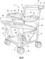
- the seat in the embodiment of Figure 5 and Figure 6 is shown as being pivotally mounted in the rear portion of the seat, which is referred to as being hinged.
- a pin is positioned in a mounting arm 58 that is part of the rear portion of the seat that acts as a hinge and allows the rear of the seat to pivot relative to the frame of the toilet.
- the mounting arm 58 may slide or telescope relative to the seat to facilitate the movement of the seat as it moves from the position in Figure 5 to the position in Figure 6 , and back.
- the toilet is preferred to be portable, and may be fitted with a caster 50 at each of the four (4) legs.
- the casters may be fitted with a locking device 54 to selectively retard movement of the toilet.
- a handle 52 may be provided for pushing or pulling the toilet.
- a control pendant may be provided.
- the control pendant 46 allows an operator to position or reposition the toilet seat by means of the actuators.
- the control pendant may also clear the call feature, indicated battery charge level, or provide other monitoring and control functions.
- the control pendant is preferred to be positioned on the back of the toilet where it is not easily accessible to a person seated in the toilet.
Landscapes
- Health & Medical Sciences (AREA)
- Public Health (AREA)
- Life Sciences & Earth Sciences (AREA)
- Animal Behavior & Ethology (AREA)
- General Health & Medical Sciences (AREA)
- Veterinary Medicine (AREA)
- Toilet Supplies (AREA)
Claims (9)
- Toilette (2), umfassend:einen Sitz (3) mit einer Öffnung (4) darin und wobei der Sitz im hinteren Abschnitt des Sitzes angelenkt ist,eine Rückenlehne (12), die mit dem Sitz verbunden ist,einen ersten Arm (10) mit einem ersten Drucksensor (18) und einen zweiten Arm mit einem zweiten Drucksensor, wobei der erste Arm und der zweite Arm voneinander beabstandet und oberhalb des Sitzes positioniert sind,ein Betätigungselement (20), das den Sitz zu einer Position bewegt, in der der Sitz von dem angelenkten hinteren Abschnitt des Sitzes zu einem vorderen Abschnitt des Sitzes nach oben geneigt ist,wobei im Gebrauch der erste Drucksensor Druck auf den ersten Arm erfasst und der zweite Drucksensor Druck auf den zweiten Arm erfasst, und auf das Erfassen von Druck durch den ersten Drucksensor oder den zweiten Drucksensor ein Signal an das Betätigungselement (20) übertragen wird, woraufhin das Betätigungselement den Sitz so bewegt, dass er von dem angelenkten hinteren Abschnitt des Sitzes zu dem vorderen Abschnitt des Sitzes nach oben geneigt wird.
- Toilette nach Anspruch 1, ferner umfassend einen Rückenlehnensensor (14), der in der Rückenlehne (12) positioniert ist, wobei der Rückenlehnensensor im Gebrauch eine Veränderung im Abstand eines Nutzers von dem Sensor erkennt und daraufhin, dass der Abstand eine Grenze überschreitet, ein Signal an das Betätigungselement übertragen wird, woraufhin das Betätigungselement den Sitz so bewegt, dass er von dem angelenkten hinteren Abschnitt des Sitzes zu dem vorderen Abschnitt des Sitzes geneigt wird.
- Toilette nach Anspruch 1 oder Anspruch 2, ferner umfassend:eine Querstange (22), die zwischen dem Paar beabstandeter Arme positioniert ist,und einen Querstangensensor (24),wobei von dem Querstangensensor im Gebrauch eine Bewegung der Querstange erkannt wird und ein Signal an das Betätigungselement übertragen wird, woraufhin das Betätigungselement den Sitz so bewegt, dass er von dem angelenkten hinteren Abschnitt des Sitzes zu dem vorderen Abschnitt des Sitzes nach oben geneigt wird.
- Toilette nach Anspruch 1 oder Anspruch 2, ferner umfassend:eine Querstange, die zwischen dem Paar beabstandeter Arme positioniert ist,
undeinen Querstangensensor,wobei von dem Querstangensensor im Gebrauch eine Bewegung der Querstange erkannt wird und der Querstangensensor ein hörbares Signal oder ein sichtbares Signal an eine Stelle überträgt, die fern der Toilette liegt. - Toilette nach Anspruch 1 oder 2, wobei der erste Drucksensor einen nach unten gerichteten Druck auf den ersten Arm erfasst und der zweite Drucksensor einen nach unten gerichteten Druck auf den zweiten Arm erfasst und daraufhin, dass der erste Drucksensor oder der zweite Drucksensor einen nach unten gerichteten Druck erfasst, ein Signal an das Betätigungselement übertragen wird, woraufhin das Betätigungselement den Sitz so bewegt, dass er von dem hinteren Abschnitt des Sitzes zu dem vorderen Abschnitt des Sitzes geneigt wird.
- Toilette nach Anspruch 1 oder Anspruch 2, wobei ein Drucksensor einen nach hinten gerichteten Druck auf den ersten Arm erfasst und ein zusätzlicher Drucksensor einen nach hinten gerichteten Druck auf den zweiten Arm erfasst und auf das Erfassen von nach hinten gerichtetem Druck durch den Drucksensor oder den zusätzlichen Drucksensor ein Signal an das Betätigungselement übertragen wird, woraufhin das Betätigungselement den Sitz so bewegt, dass er von dem hinteren Abschnitt des Sitzes zu dem vorderen Abschnitt des Sitzes geneigt wird.
- Toilette nach Anspruch 1 oder Anspruch 2, wobei das Betätigungselement durch Luftdruck betätigt wird.
- Toilette nach Anspruch 1 oder Anspruch 2, wobei das Betätigungselement durch Hydraulikdruck betätigt wird.
- Toilette nach Anspruch 1 oder Anspruch 2, wobei das Betätigungselement elektrisch betätigt wird.
Applications Claiming Priority (2)
| Application Number | Priority Date | Filing Date | Title |
|---|---|---|---|
| US15/423,248 US10188245B2 (en) | 2015-08-26 | 2017-02-02 | Toilet |
| PCT/US2018/016554 WO2018144793A1 (en) | 2017-02-02 | 2018-02-02 | Toilet |
Publications (4)
| Publication Number | Publication Date |
|---|---|
| EP3576587A1 EP3576587A1 (de) | 2019-12-11 |
| EP3576587A4 EP3576587A4 (de) | 2020-10-21 |
| EP3576587B1 true EP3576587B1 (de) | 2024-09-25 |
| EP3576587C0 EP3576587C0 (de) | 2024-09-25 |
Family
ID=63041085
Family Applications (1)
| Application Number | Title | Priority Date | Filing Date |
|---|---|---|---|
| EP18747808.6A Active EP3576587B1 (de) | 2017-02-02 | 2018-02-02 | Toilette |
Country Status (4)
| Country | Link |
|---|---|
| EP (1) | EP3576587B1 (de) |
| AU (1) | AU2018217134B2 (de) |
| CA (1) | CA3052284A1 (de) |
| WO (1) | WO2018144793A1 (de) |
Family Cites Families (7)
| Publication number | Priority date | Publication date | Assignee | Title |
|---|---|---|---|---|
| US6792626B1 (en) * | 2001-06-18 | 2004-09-21 | Bryan Smeal | Apparatus for lowering toilet seat |
| WO2006023539A2 (en) * | 2004-08-16 | 2006-03-02 | Kramer Kenneth L | Home care equipment system |
| US20060042005A1 (en) * | 2004-09-02 | 2006-03-02 | Johnson Dan C | Power lifting toilet chair |
| US20100219668A1 (en) * | 2006-05-12 | 2010-09-02 | Liftseat Corporation | Devices and Methods for Lift Assistance |
| US7900297B2 (en) * | 2007-12-10 | 2011-03-08 | Shao-Yu Peng | Movably auxiliary sanitary care apparatus |
| CN104060663B (zh) * | 2014-06-30 | 2016-06-29 | 科勒(中国)投资有限公司 | 用于座便器的坐姿提醒装置 |
| US9770144B2 (en) * | 2015-08-26 | 2017-09-26 | Robert Rife | Toilet |
-
2018
- 2018-02-02 WO PCT/US2018/016554 patent/WO2018144793A1/en not_active Ceased
- 2018-02-02 CA CA3052284A patent/CA3052284A1/en active Pending
- 2018-02-02 AU AU2018217134A patent/AU2018217134B2/en active Active
- 2018-02-02 EP EP18747808.6A patent/EP3576587B1/de active Active
Also Published As
| Publication number | Publication date |
|---|---|
| EP3576587A4 (de) | 2020-10-21 |
| CA3052284A1 (en) | 2018-08-09 |
| EP3576587C0 (de) | 2024-09-25 |
| WO2018144793A1 (en) | 2018-08-09 |
| EP3576587A1 (de) | 2019-12-11 |
| AU2018217134A1 (en) | 2019-08-15 |
| AU2018217134B2 (en) | 2023-08-10 |
Similar Documents
| Publication | Publication Date | Title |
|---|---|---|
| EP3340847B1 (de) | Toilette | |
| US10736473B2 (en) | Toilet | |
| US10188245B2 (en) | Toilet | |
| US6822571B2 (en) | Patient movement detection system for a bed including a load cell mounting assembly | |
| US20210007919A1 (en) | Person support apparatuses with exit detection systems | |
| EP2695592B1 (de) | Leistungsantriebssystem für Personentragevorrichtung | |
| US4633237A (en) | Patient bed alarm system | |
| EP3527187B1 (de) | Seitengitter | |
| US9433552B2 (en) | Electric walking assistant device | |
| US20120182148A1 (en) | Bed pre-exit patient monitor | |
| US20100033331A1 (en) | Monitoring System | |
| US12551393B2 (en) | Patient support apparatuses with exit detection systems | |
| US20150137567A1 (en) | Lifting and lowering chair | |
| US20190183703A1 (en) | User Controls For Patient Support Apparatus Having Low Height | |
| WO2010095098A1 (en) | System and method for bed height adjustment | |
| HUE026996T2 (en) | Electric drive system | |
| JP2023543534A (ja) | 障害物応答を行う退出検出システム | |
| CN212484515U (zh) | 具有感测警报装置的站立式辅助装置 | |
| KR101752994B1 (ko) | 휠체어 | |
| AU1055800A (en) | Control of powered furniture | |
| EP3576587B1 (de) | Toilette | |
| US20060179567A1 (en) | Helping hand chair |
Legal Events
| Date | Code | Title | Description |
|---|---|---|---|
| STAA | Information on the status of an ep patent application or granted ep patent |
Free format text: STATUS: THE INTERNATIONAL PUBLICATION HAS BEEN MADE |
|
| PUAI | Public reference made under article 153(3) epc to a published international application that has entered the european phase |
Free format text: ORIGINAL CODE: 0009012 |
|
| STAA | Information on the status of an ep patent application or granted ep patent |
Free format text: STATUS: REQUEST FOR EXAMINATION WAS MADE |
|
| 17P | Request for examination filed |
Effective date: 20190806 |
|
| AK | Designated contracting states |
Kind code of ref document: A1 Designated state(s): AL AT BE BG CH CY CZ DE DK EE ES FI FR GB GR HR HU IE IS IT LI LT LU LV MC MK MT NL NO PL PT RO RS SE SI SK SM TR |
|
| AX | Request for extension of the european patent |
Extension state: BA ME |
|
| DAV | Request for validation of the european patent (deleted) | ||
| DAX | Request for extension of the european patent (deleted) | ||
| A4 | Supplementary search report drawn up and despatched |
Effective date: 20200921 |
|
| RIC1 | Information provided on ipc code assigned before grant |
Ipc: A47K 13/28 20060101ALI20200915BHEP Ipc: A61G 7/14 20060101ALI20200915BHEP Ipc: A47K 13/10 20060101AFI20200915BHEP Ipc: A61G 7/10 20060101ALI20200915BHEP Ipc: A61G 5/14 20060101ALI20200915BHEP Ipc: A47K 13/24 20060101ALI20200915BHEP Ipc: A47K 11/04 20060101ALI20200915BHEP |
|
| GRAP | Despatch of communication of intention to grant a patent |
Free format text: ORIGINAL CODE: EPIDOSNIGR1 |
|
| STAA | Information on the status of an ep patent application or granted ep patent |
Free format text: STATUS: GRANT OF PATENT IS INTENDED |
|
| INTG | Intention to grant announced |
Effective date: 20231107 |
|
| GRAJ | Information related to disapproval of communication of intention to grant by the applicant or resumption of examination proceedings by the epo deleted |
Free format text: ORIGINAL CODE: EPIDOSDIGR1 |
|
| STAA | Information on the status of an ep patent application or granted ep patent |
Free format text: STATUS: REQUEST FOR EXAMINATION WAS MADE |
|
| INTC | Intention to grant announced (deleted) | ||
| GRAP | Despatch of communication of intention to grant a patent |
Free format text: ORIGINAL CODE: EPIDOSNIGR1 |
|
| STAA | Information on the status of an ep patent application or granted ep patent |
Free format text: STATUS: GRANT OF PATENT IS INTENDED |
|
| INTG | Intention to grant announced |
Effective date: 20240417 |
|
| GRAS | Grant fee paid |
Free format text: ORIGINAL CODE: EPIDOSNIGR3 |
|
| GRAA | (expected) grant |
Free format text: ORIGINAL CODE: 0009210 |
|
| STAA | Information on the status of an ep patent application or granted ep patent |
Free format text: STATUS: THE PATENT HAS BEEN GRANTED |
|
| AK | Designated contracting states |
Kind code of ref document: B1 Designated state(s): AL AT BE BG CH CY CZ DE DK EE ES FI FR GB GR HR HU IE IS IT LI LT LU LV MC MK MT NL NO PL PT RO RS SE SI SK SM TR |
|
| REG | Reference to a national code |
Ref country code: GB Ref legal event code: FG4D |
|
| REG | Reference to a national code |
Ref country code: CH Ref legal event code: EP |
|
| REG | Reference to a national code |
Ref country code: DE Ref legal event code: R096 Ref document number: 602018074709 Country of ref document: DE |
|
| REG | Reference to a national code |
Ref country code: IE Ref legal event code: FG4D |
|
| U01 | Request for unitary effect filed |
Effective date: 20241023 |
|
| U07 | Unitary effect registered |
Designated state(s): AT BE BG DE DK EE FI FR IT LT LU LV MT NL PT RO SE SI Effective date: 20241105 |
|
| PG25 | Lapsed in a contracting state [announced via postgrant information from national office to epo] |
Ref country code: NO Free format text: LAPSE BECAUSE OF FAILURE TO SUBMIT A TRANSLATION OF THE DESCRIPTION OR TO PAY THE FEE WITHIN THE PRESCRIBED TIME-LIMIT Effective date: 20241225 |
|
| PG25 | Lapsed in a contracting state [announced via postgrant information from national office to epo] |
Ref country code: GR Free format text: LAPSE BECAUSE OF FAILURE TO SUBMIT A TRANSLATION OF THE DESCRIPTION OR TO PAY THE FEE WITHIN THE PRESCRIBED TIME-LIMIT Effective date: 20241226 |
|
| PG25 | Lapsed in a contracting state [announced via postgrant information from national office to epo] |
Ref country code: RS Free format text: LAPSE BECAUSE OF FAILURE TO SUBMIT A TRANSLATION OF THE DESCRIPTION OR TO PAY THE FEE WITHIN THE PRESCRIBED TIME-LIMIT Effective date: 20241225 |
|
| PG25 | Lapsed in a contracting state [announced via postgrant information from national office to epo] |
Ref country code: RS Free format text: LAPSE BECAUSE OF FAILURE TO SUBMIT A TRANSLATION OF THE DESCRIPTION OR TO PAY THE FEE WITHIN THE PRESCRIBED TIME-LIMIT Effective date: 20241225 Ref country code: NO Free format text: LAPSE BECAUSE OF FAILURE TO SUBMIT A TRANSLATION OF THE DESCRIPTION OR TO PAY THE FEE WITHIN THE PRESCRIBED TIME-LIMIT Effective date: 20241225 Ref country code: GR Free format text: LAPSE BECAUSE OF FAILURE TO SUBMIT A TRANSLATION OF THE DESCRIPTION OR TO PAY THE FEE WITHIN THE PRESCRIBED TIME-LIMIT Effective date: 20241226 |
|
| U20 | Renewal fee for the european patent with unitary effect paid |
Year of fee payment: 8 Effective date: 20250226 |
|
| PG25 | Lapsed in a contracting state [announced via postgrant information from national office to epo] |
Ref country code: IS Free format text: LAPSE BECAUSE OF FAILURE TO SUBMIT A TRANSLATION OF THE DESCRIPTION OR TO PAY THE FEE WITHIN THE PRESCRIBED TIME-LIMIT Effective date: 20250125 |
|
| PG25 | Lapsed in a contracting state [announced via postgrant information from national office to epo] |
Ref country code: SM Free format text: LAPSE BECAUSE OF FAILURE TO SUBMIT A TRANSLATION OF THE DESCRIPTION OR TO PAY THE FEE WITHIN THE PRESCRIBED TIME-LIMIT Effective date: 20240925 |
|
| PG25 | Lapsed in a contracting state [announced via postgrant information from national office to epo] |
Ref country code: ES Free format text: LAPSE BECAUSE OF FAILURE TO SUBMIT A TRANSLATION OF THE DESCRIPTION OR TO PAY THE FEE WITHIN THE PRESCRIBED TIME-LIMIT Effective date: 20240925 |
|
| PG25 | Lapsed in a contracting state [announced via postgrant information from national office to epo] |
Ref country code: CZ Free format text: LAPSE BECAUSE OF FAILURE TO SUBMIT A TRANSLATION OF THE DESCRIPTION OR TO PAY THE FEE WITHIN THE PRESCRIBED TIME-LIMIT Effective date: 20240925 Ref country code: PL Free format text: LAPSE BECAUSE OF FAILURE TO SUBMIT A TRANSLATION OF THE DESCRIPTION OR TO PAY THE FEE WITHIN THE PRESCRIBED TIME-LIMIT Effective date: 20240925 |
|
| PG25 | Lapsed in a contracting state [announced via postgrant information from national office to epo] |
Ref country code: SK Free format text: LAPSE BECAUSE OF FAILURE TO SUBMIT A TRANSLATION OF THE DESCRIPTION OR TO PAY THE FEE WITHIN THE PRESCRIBED TIME-LIMIT Effective date: 20240925 |
|
| PLBE | No opposition filed within time limit |
Free format text: ORIGINAL CODE: 0009261 |
|
| STAA | Information on the status of an ep patent application or granted ep patent |
Free format text: STATUS: NO OPPOSITION FILED WITHIN TIME LIMIT |
|
| 26N | No opposition filed |
Effective date: 20250626 |
|
| PG25 | Lapsed in a contracting state [announced via postgrant information from national office to epo] |
Ref country code: MC Free format text: LAPSE BECAUSE OF FAILURE TO SUBMIT A TRANSLATION OF THE DESCRIPTION OR TO PAY THE FEE WITHIN THE PRESCRIBED TIME-LIMIT Effective date: 20240925 |
|
| REG | Reference to a national code |
Ref country code: CH Ref legal event code: PL |
|
| PG25 | Lapsed in a contracting state [announced via postgrant information from national office to epo] |
Ref country code: CH Free format text: LAPSE BECAUSE OF NON-PAYMENT OF DUE FEES Effective date: 20250228 |
|
| PG25 | Lapsed in a contracting state [announced via postgrant information from national office to epo] |
Ref country code: HR Free format text: LAPSE BECAUSE OF FAILURE TO SUBMIT A TRANSLATION OF THE DESCRIPTION OR TO PAY THE FEE WITHIN THE PRESCRIBED TIME-LIMIT Effective date: 20240925 |
|
| PG25 | Lapsed in a contracting state [announced via postgrant information from national office to epo] |
Ref country code: IE Free format text: LAPSE BECAUSE OF NON-PAYMENT OF DUE FEES Effective date: 20250202 |
|
| U20 | Renewal fee for the european patent with unitary effect paid |
Year of fee payment: 9 Effective date: 20260225 |
|
| PGFP | Annual fee paid to national office [announced via postgrant information from national office to epo] |
Ref country code: GB Payment date: 20260302 Year of fee payment: 9 |