EP3576593B1 - Apparail de nettoyage de surfaces - Google Patents
Apparail de nettoyage de surfaces Download PDFInfo
- Publication number
- EP3576593B1 EP3576593B1 EP18706591.7A EP18706591A EP3576593B1 EP 3576593 B1 EP3576593 B1 EP 3576593B1 EP 18706591 A EP18706591 A EP 18706591A EP 3576593 B1 EP3576593 B1 EP 3576593B1
- Authority
- EP
- European Patent Office
- Prior art keywords
- valve
- fluid
- cleaning apparatus
- surface cleaning
- outlet
- Prior art date
- Legal status (The legal status is an assumption and is not a legal conclusion. Google has not performed a legal analysis and makes no representation as to the accuracy of the status listed.)
- Active
Links
Images


Classifications
-
- A—HUMAN NECESSITIES
- A47—FURNITURE; DOMESTIC ARTICLES OR APPLIANCES; COFFEE MILLS; SPICE MILLS; SUCTION CLEANERS IN GENERAL
- A47L—DOMESTIC WASHING OR CLEANING; SUCTION CLEANERS IN GENERAL
- A47L11/00—Machines for cleaning floors, carpets, furniture, walls, or wall coverings
- A47L11/02—Floor surfacing or polishing machines
- A47L11/20—Floor surfacing or polishing machines combined with vacuum cleaning devices
- A47L11/201—Floor surfacing or polishing machines combined with vacuum cleaning devices with supply of cleaning agents
-
- A—HUMAN NECESSITIES
- A47—FURNITURE; DOMESTIC ARTICLES OR APPLIANCES; COFFEE MILLS; SPICE MILLS; SUCTION CLEANERS IN GENERAL
- A47L—DOMESTIC WASHING OR CLEANING; SUCTION CLEANERS IN GENERAL
- A47L11/00—Machines for cleaning floors, carpets, furniture, walls, or wall coverings
- A47L11/02—Floor surfacing or polishing machines
- A47L11/04—Floor surfacing or polishing machines hand-driven
- A47L11/06—Floor surfacing or polishing machines hand-driven with reciprocating or oscillating tools
-
- A—HUMAN NECESSITIES
- A47—FURNITURE; DOMESTIC ARTICLES OR APPLIANCES; COFFEE MILLS; SPICE MILLS; SUCTION CLEANERS IN GENERAL
- A47L—DOMESTIC WASHING OR CLEANING; SUCTION CLEANERS IN GENERAL
- A47L11/00—Machines for cleaning floors, carpets, furniture, walls, or wall coverings
- A47L11/34—Machines for treating carpets in position by liquid, foam, or vapour, e.g. by steam
-
- A—HUMAN NECESSITIES
- A47—FURNITURE; DOMESTIC ARTICLES OR APPLIANCES; COFFEE MILLS; SPICE MILLS; SUCTION CLEANERS IN GENERAL
- A47L—DOMESTIC WASHING OR CLEANING; SUCTION CLEANERS IN GENERAL
- A47L11/00—Machines for cleaning floors, carpets, furniture, walls, or wall coverings
- A47L11/40—Parts or details of machines not provided for in groups A47L11/02 - A47L11/38, or not restricted to one of these groups, e.g. handles, arrangements of switches, skirts, buffers, levers
- A47L11/4036—Parts or details of the surface treating tools
-
- A—HUMAN NECESSITIES
- A47—FURNITURE; DOMESTIC ARTICLES OR APPLIANCES; COFFEE MILLS; SPICE MILLS; SUCTION CLEANERS IN GENERAL
- A47L—DOMESTIC WASHING OR CLEANING; SUCTION CLEANERS IN GENERAL
- A47L11/00—Machines for cleaning floors, carpets, furniture, walls, or wall coverings
- A47L11/40—Parts or details of machines not provided for in groups A47L11/02 - A47L11/38, or not restricted to one of these groups, e.g. handles, arrangements of switches, skirts, buffers, levers
- A47L11/408—Means for supplying cleaning or surface treating agents
-
- A—HUMAN NECESSITIES
- A47—FURNITURE; DOMESTIC ARTICLES OR APPLIANCES; COFFEE MILLS; SPICE MILLS; SUCTION CLEANERS IN GENERAL
- A47L—DOMESTIC WASHING OR CLEANING; SUCTION CLEANERS IN GENERAL
- A47L11/00—Machines for cleaning floors, carpets, furniture, walls, or wall coverings
- A47L11/40—Parts or details of machines not provided for in groups A47L11/02 - A47L11/38, or not restricted to one of these groups, e.g. handles, arrangements of switches, skirts, buffers, levers
- A47L11/408—Means for supplying cleaning or surface treating agents
- A47L11/4083—Liquid supply reservoirs; Preparation of the agents, e.g. mixing devices
-
- A—HUMAN NECESSITIES
- A47—FURNITURE; DOMESTIC ARTICLES OR APPLIANCES; COFFEE MILLS; SPICE MILLS; SUCTION CLEANERS IN GENERAL
- A47L—DOMESTIC WASHING OR CLEANING; SUCTION CLEANERS IN GENERAL
- A47L11/00—Machines for cleaning floors, carpets, furniture, walls, or wall coverings
- A47L11/40—Parts or details of machines not provided for in groups A47L11/02 - A47L11/38, or not restricted to one of these groups, e.g. handles, arrangements of switches, skirts, buffers, levers
- A47L11/408—Means for supplying cleaning or surface treating agents
- A47L11/4088—Supply pumps; Spraying devices; Supply conduits
-
- A—HUMAN NECESSITIES
- A47—FURNITURE; DOMESTIC ARTICLES OR APPLIANCES; COFFEE MILLS; SPICE MILLS; SUCTION CLEANERS IN GENERAL
- A47L—DOMESTIC WASHING OR CLEANING; SUCTION CLEANERS IN GENERAL
- A47L13/00—Implements for cleaning floors, carpets, furniture, walls, or wall coverings
- A47L13/10—Scrubbing; Scouring; Cleaning; Polishing
- A47L13/20—Mops
- A47L13/22—Mops with liquid-feeding devices
Definitions
- This invention relates to a surface cleaning apparatus. More particularly, but not exclusively, this invention relates to a vacuum cleaner which is capable of washing carpets or other hard floor surfaces including a valve that is configurable to regulate the flow of fluid to the surface. Such cleaners are commonly referred to as wet vacuum cleaners.
- wet vacuum cleaners for cleaning floor surfaces.
- Known wet vacuum cleaners typically have a floor head which is adapted to be moved over a surface to be cleaned.
- the floor head may carry a cleaning element such as a fabric/textile or other material which is able to absorb liquid.
- the floor head may alternatively or additionally be equipped with an agitator as is well known in the art to agitate the surface to remove dirt entrained therein.
- a fluid can be emitted from the cleaner onto the surface to be cleaned which can have the effect of loosening dirt from the surface.
- the fluid (which is typically a liquid) can be provided with additives to improve the cleaning effect.
- a suction inlet is typically used in combination with a source of suction to remove the dirty cleaning fluid from the surface.
- WO 2005/038318 A1 discloses a surface cleaning apparatus.
- a fluid delivery system conveys fluid from a reservoir to the surface proximate an agitating mechanism.
- the fluid delivery system includes a flow control valve having a body and a flow control member in the form of a ball constrained within the body and rotatable about an axis.
- US 2005/0283940 A1 discloses a surface cleaning apparatus.
- the apparatus includes an elastomeric valve member comprising an elongated piston extending through a valve seat having a bulbous nose at the distal end thereof.
- the elongated piston is generally divided into three sections of different diameters that correspond to different flow rates.
- a problem associated with prior art cleaners is that there is no simple way of controlling the flow of fluid emitted from the cleaner to the surface.
- Embodiments of this invention seek to overcome, or at least substantially reduce, this problem.
- a surface cleaning apparatus including:
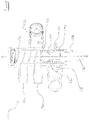
- the apparatus 10 includes a floor head 12 which may be pivotably connected to a user graspable handle 14 and a fluid storage container 16 for holding a quantity of cleaning fluid to be dispensed onto a surface to be cleaned.
- the cleaning fluid is typically a liquid provided with cleaning additives.
- a fluid recovery container 18 and a source of suction are provided, so that fluid that has been dispensed onto the surface to be cleaned may be removed by suction and stored. The fluid recovering container 18 may then be emptied after the apparatus 10 has been used.
- the apparatus 10 is a wet vacuum cleaner although it is to be appreciated that the vacuum cleaner may perform equally effectively as a dry vacuum cleaner.
- a pump 20 may be provided that is configured to pump cleaning fluid from the fluid storage container 16 to an outlet 22 of the apparatus 10.
- the pump 20 may be user operable so that a user can control at what stage fluid is to be emitted from the outlet 22.
- the outlet 22 directs fluid from the fluid storage container 16 onto a surface to be cleaned.
- the pump 20 may be fluidly located between the fluid storage container 16 and a valve 30.
- fluidly located it is meant that fluid passes from the fluid storage container 16 to the pump 20 and then to the valve 30.
- the components of the cleaner do not necessarily need to be positioned spatially in that order in the apparatus 10. All that is required is that fluid passes between those components in that order.
- the valve 30 is configured to regulate the flow of fluid from the fluid storage container 16 to the outlet 22.
- the pump 20 may be fluidly located between the valve 30 and the outlet 22.
- valve 30 may be located in the floor head 12. Alternatively, in some embodiments the valve 30 may be located elsewhere; for example, the valve 30 may be located in a main housing of the apparatus 10, or in or adjacent the fluid storage container 16 or pump 20.
- the floor head 12 may be provided with a suction nozzle operatively connected to the source of suction and the fluid recovery container 18.
- a first fluid passage may be provided between the fluid storage container 16 and the pump 20.
- a second fluid passage may be provided between the pump 20 and the valve 30.
- a third fluid passage may be provided between the valve 30 and the outlet 22.
- the apparatus 10 need not be provided with a pump 20 for pumping fluid from the fluid storage container 16 to the valve 30.
- fluid may be fed between the fluid storage container 16 and the valve 30 by gravity.
- an on-off switch (not shown) may be provided between the fluid storage container 16 and the valve 30 to offer the user a way of stopping the flow of fluid to the valve 30.
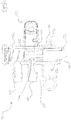
- the valve 30 includes a body 32 and a member 34.
- the member 34 is moveable relative to the body 32 between a first position and a second position.
- the member 34 also defines a flow path 36 which extends through a surface 38 of the member 34.
- the flow of fluid through the valve 30 flows at a first rate when the member 34 is in the first position ( figures 2a and 2b ) and at a second rate and along the flow path 36 when the member 34 is in the second position ( figures 2a and 2b ). It is to be appreciated that the second rate of flow is lower than the first rate of flow.
- the apparatus 10 to have at least two cleaning modes: a first cleaning mode where the rate of fluid flow is higher than in a second mode. Having more than one cleaning mode is advantageous because it provides the user with selectivity. For instance, operating the apparatus 10 in the first cleaning mode has an advantage that a surface is thoroughly cleaned due to the high volume of cleaning fluid that is dispensed. Equally, operating the apparatus 10 in the second cleaning mode has an advantage that a greater surface area can be cleaned with the same volume of cleaning fluid, when compared to operation in the first cleaning mode. Operation in the second cleaning mode also provides for faster drying of a surface since less cleaning fluid will have been dispensed.
- the body 32 may define an axis A about which the member 34 is rotatable between its first and second positions.
- the member 34 may define a cavity 40.
- the cavity 40 may be in fluid communication with the flow path 36.
- the flow path 36 may define a fluid flow path axis B along which fluid flows, the flow path axis B being substantially orthogonal to the axis A of the body 32.
- the cavity 40 may be generally elongate and extend in a direction along the axis A of the body 32.
- the member 34 is configured to permit a continuous flow of fluid through the valve 30 as the member 34 moves between its first and second positions. In other words, the member 34 cannot adopt a position whereby flow of fluid through the valve 30 is stopped. This is particularly advantageous because it ensures that there can be no discontinuity in the supply of fluid to the outlet 22 as the member 34 moves between its first and second positions, thus mitigating the risk that the valve 30 might become damaged, e.g. due to excessive pressure building up between the pump and the valve 30, or from causing the second fluid passage to become disconnected from the pump or valve.
- a further flow path may be provided in the member 34.
- the member 34 may be moveable relative to the body 32 between first, second and third positions.
- the flow of fluid through the valve 30 flows at a first rate when the member 34 is in the first position; a second rate and along the flow path 36 when the member 34 is in the second position; and at a third rate and along the further flow path when the member is in the third position.
- the third rate of flow is lower than the second rate of flow and the first rate of flow. This provides a further third cleaning mode when the third rate of fluid flow is provided.
- the body 32 may include one or both of a valve inlet 42 and a valve outlet 44.
- the second fluid passage is connected to the valve inlet 42 and the third fluid passage is connected to the valve outlet 44.
- the valve inlet 42 and valve outlet 44 may be provided with spigots to permit the push fitting of the second and third fluid passages thereon.
- the outlet 22 is the valve outlet 42. In those embodiments only first and second fluid passages are provided.
- a further valve outlet may be provided with a further fluid passage to a further outlet (not shown).
- the flow path 36 may permit the flow of fluid through both the valve outlet 44 and the further valve outlet.
- the flow path 36 of the member 34 is positioned adjacent the valve outlet 44 when the member 34 is in the second position.
- the flow path 36 of the member 34 may be positioned adjacent the valve inlet 42 when the member 34 is in the second position.
- the flow path 36 advantageously has a smaller cross-sectional area than that of the valve inlet 42, or valve outlet 44. It is to be appreciated, therefore, that the flow path 36 causes a restriction on the flow of fluid through the valve 30 when the member is in the second position.
- the valve 30 is provided with a user control 46 in the form of a dial which is operatively associated with the member 34 so that a user can move the member 34 between its first and second positions upon actuation of the user control 46. It should be appreciated that other forms of user control, such as a lever, could be used without departing from the scope of the present invention.
- valve inlet 42 and the valve outlet 44 are diametrically opposed. This is advantageous as it ensures a smooth, laminar flow of fluid through the valve 30 in the first position at least.
- the valve inlet 42 and the valve outlet 44 define a valve axis C.
- the flow path axis B is substantially orthogonal to the valve axis C when the member 34 is in the first position and the flow path axis B is substantially parallel to the valve axis C when the member 34 is in the second position.
- the valve inlet 42 and the valve outlet 44 may be spaced apart from one another along the axis A or another axis of the body 32. This may, advantageously, permit the valve 30 to be mounted in a more compact configuration in the apparatus 16, and may also make replacement of the valve 30 easier.
- the body 32 and the member 34 may each have a generally circular cross-sectional area and be arranged generally concentrically with each other. Alternatively, the body 32 may be provided with a different cross-sectional area, such as rectangular, without departing from the scope of the present invention.
- the member 34 may also be provided with O-rings 48, 50 to produce a fluid tight seal between the member 34 and the body 32.
- the valve 30 may also be provided with brackets 52, 54 to permit the valve 30 to be mounted onto the apparatus 10.
- the member 34 is rotatably moveable relative to the body 32 about the axis A.
- the member 34 may be rotatably moveable through about 90 degrees from the first position to the second position, although the range of motion may be greater than or less than 90 degrees.
- the member 34 may be biased, preferably resiliently biased, towards the first position by a biasing device, e.g. a torsion spring. Alternatively, the member 34 may be biased, preferably resiliently, towards the second position.
- the surface cleaning apparatus 10 may also be provided with a locking device (not shown) configurable to lock the member 34 in one or both of the first and second positions.
- FIGS 4 and 5 show a valve 130 according to an embodiment of the invention.
- Features in common with the valve 30 shown in figures 2 and 3 have been given the same reference numeral but with the addition of 100.
- valve 130 is utilised in the apparatus 10 of figure 1 .
- Valve 130 has all the features of the valve 30 with the exception of the following.
- the member 134 includes a cavity 140 which is generally elongate and extends in a direction along an axis A of the body 132.
- valve inlet 142 and the valve outlet 144 of the valve 130 are spaced apart from one another along the axis A, rather than being un-spaced along the axis A.
- valve inlet 142 and the valve outlet 144 are provided on the same side of the body 132, rather than being diametrically opposed.
- the member 134 is axially moveable along the axis A, rather than being rotatably moveable about axis A.
- the member 134 may be axially moveable along and rotatably moveable about axis A.
- the flow path 136 of the member 134 is adjacent the valve inlet 142 when the member 136 is in the second position.
- the member 134 is biased, preferably resiliently biased, towards the first position by a biasing device 156, e.g. a coil spring.
- a biasing device 156 e.g. a coil spring.
- the surface cleaning apparatus 10 is a wet/dry style upright vacuum cleaner.
- the apparatus 10 could take the form of a cylinder vacuum cleaner, a stick type vacuum cleaner, a spot cleaner or a hand held vacuum cleaner. It is also to be appreciated that the apparatus 10 may alternatively be provided as a mop type cleaner.
Landscapes
- Cleaning Implements For Floors, Carpets, Furniture, Walls, And The Like (AREA)
- Cleaning In General (AREA)
- Cleaning By Liquid Or Steam (AREA)
- Lift Valve (AREA)
Claims (13)
- Un appareil de nettoyage de surface (10) incluant :un contenant de stockage de fluide (16) ;un orifice de sortie (22) pour diriger un fluide depuis le contenant de stockage de fluide sur une surface à nettoyer ; etune vanne (130) configurée pour réguler l'écoulement de fluide allant du contenant de stockage de fluide à l'orifice de sortie et incluant :caractérisé en ce que le corps définit un axe (A-A) le long duquel l'élément est mobile axialement.un corps (132) ; etun élément (134) qui est mobile par rapport au corps entre une première position et une deuxième position et qui définit un trajet d'écoulement (136) s'étendant à travers une surface (138) de celui-ci ;dans lequel l'écoulement de fluide à travers la vanne s'écoule à un premier débit lorsque l'élément est à la première position et à un deuxième débit et le long du trajet d'écoulement lorsque l'élément est à la deuxième position, le deuxième débit étant inférieur au premier débit,
- Un appareil de nettoyage de surface (10) selon la revendication 1, dans lequel l'élément (134) définit une cavité (140).
- Un appareil de nettoyage de surface (10) selon la revendication 2, dans lequel la cavité (140) est en communication fluidique avec le trajet d'écoulement (136).
- Un appareil de nettoyage de surface (10) selon l'une quelconque des revendications précédentes, dans lequel le trajet d'écoulement (136) définit un axe de trajet d'écoulement le long duquel le fluide s'écoule, l'axe de trajet d'écoulement étant sensiblement perpendiculaire à l'axe (A-A) du corps (132).
- Un appareil de nettoyage de surface (10) selon l'une quelconque des revendications 2 à 4, dans lequel la cavité (140) est généralement allongée et s'étend dans une direction le long de l'axe (A-A) du corps (132).
- Un appareil de nettoyage de surface (10) selon l'une quelconque des revendications précédentes, dans lequel l'élément (134) est configuré pour permettre un écoulement continu de fluide à travers la vanne (130) à mesure que l'élément se déplace entre les première et deuxième positions.
- Un appareil de nettoyage de surface (10) selon l'une quelconque des revendications précédentes, dans lequel le corps (132) inclut soit une entrée de vanne (142), soit une sortie de vanne (144), soit les deux.
- Un appareil de nettoyage de surface (10) selon la revendication 7, dans lequel la sortie de vanne (144) est l'orifice de sortie (22).
- Un appareil de nettoyage de surface (10) selon l'une quelconque des revendications 7 à 8, dans lequel l'entrée de vanne (142) et la sortie de vanne (144) sont espacées l'une de l'autre le long de l'axe (A-A) du corps (132).
- Un appareil de nettoyage de surface (10) selon l'une quelconque des revendications précédentes, dans lequel une commande d'utilisateur est associée fonctionnellement à l'élément (134) de telle sorte qu'un utilisateur peut déplacer l'élément entre les première et deuxième positions lors de l'actionnement de la commande d'utilisateur.
- Un appareil de nettoyage de surface (10) selon l'une quelconque des revendications précédentes, incluant un dispositif de verrouillage configurable pour verrouiller l'élément (134) dans soit la première position, soit la deuxième position, soit les deux.
- Un appareil de nettoyage de surface (10) selon l'une quelconque des revendications précédentes incluant une pompe (20) configurée pour pomper du fluide depuis le contenant de stockage de fluide (16) à l'orifice de sortie (22) ; ou incluant une pompe configurée pour pomper du fluide depuis le contenant de stockage de fluide à l'orifice de sortie et dans lequel la pompe est située de manière fluidique entre le contenant de stockage de fluide et la vanne (130).
- Un appareil de nettoyage de surface (10) selon l'une quelconque des revendications précédentes, dans lequel l'appareil inclut une tête de sol (12) ; ou dans lequel l'appareil inclut une tête de sol et dans lequel la vanne (130) est située dans la tête de sol.
Applications Claiming Priority (2)
| Application Number | Priority Date | Filing Date | Title |
|---|---|---|---|
| GB1701567.8A GB2559192B (en) | 2017-01-31 | 2017-01-31 | A surface cleaning apparatus |
| PCT/US2018/015707 WO2018144380A1 (fr) | 2017-01-31 | 2018-01-29 | Appareil de nettoyage de surface |
Publications (2)
| Publication Number | Publication Date |
|---|---|
| EP3576593A1 EP3576593A1 (fr) | 2019-12-11 |
| EP3576593B1 true EP3576593B1 (fr) | 2022-12-07 |
Family
ID=58462604
Family Applications (1)
| Application Number | Title | Priority Date | Filing Date |
|---|---|---|---|
| EP18706591.7A Active EP3576593B1 (fr) | 2017-01-31 | 2018-01-29 | Apparail de nettoyage de surfaces |
Country Status (5)
| Country | Link |
|---|---|
| US (1) | US11363931B2 (fr) |
| EP (1) | EP3576593B1 (fr) |
| CN (1) | CN110198652B (fr) |
| GB (1) | GB2559192B (fr) |
| WO (1) | WO2018144380A1 (fr) |
Families Citing this family (10)
| Publication number | Priority date | Publication date | Assignee | Title |
|---|---|---|---|---|
| USD910945S1 (en) * | 2019-02-14 | 2021-02-16 | Bissell Inc. | Upright multi-surface vacuum cleaner |
| USD928433S1 (en) * | 2019-03-18 | 2021-08-17 | Bissell Inc. | Vacuum cleaner |
| USD924504S1 (en) * | 2019-03-18 | 2021-07-06 | Bissell Inc. | Vacuum cleaner |
| USD924505S1 (en) * | 2019-03-18 | 2021-07-06 | Bissell Inc. | Vacuum cleaner |
| USD928432S1 (en) * | 2019-03-18 | 2021-08-17 | Bissell Inc. | Vacuum cleaner |
| USD917810S1 (en) | 2019-03-20 | 2021-04-27 | Bissell Inc. | Multi-surface vacuum cleaner |
| USD926405S1 (en) * | 2019-05-16 | 2021-07-27 | Bissell Inc. | Upright multi-surface vacuum cleaner |
| USD1064469S1 (en) * | 2020-12-21 | 2025-02-25 | Tineco Intelligent Technology Co., Ltd. | Cleaning machine |
| CA3152680C (fr) | 2021-03-17 | 2025-02-11 | Dupray Ventures Inc. | Appareil de nettoyage des taches |
| USD1017156S1 (en) | 2022-05-09 | 2024-03-05 | Dupray Ventures Inc. | Cleaner |
Family Cites Families (15)
| Publication number | Priority date | Publication date | Assignee | Title |
|---|---|---|---|---|
| US6158081A (en) * | 1995-11-06 | 2000-12-12 | Bissell Homecare, Inc. | Water extraction cleaning machine with variable solution mixing valve |
| US6438797B1 (en) * | 2001-03-15 | 2002-08-27 | Carrand Companies, Inc. | Mop handle with improved water flow control |
| CA2386877C (fr) * | 2001-05-21 | 2006-08-29 | The Hoover Company | Dispositif et methode de nettoyage d'une surface |
| CN2560804Y (zh) * | 2002-07-22 | 2003-07-16 | 周道珠 | 自动防漏燃气保护器 |
| WO2005032735A2 (fr) | 2003-09-29 | 2005-04-14 | Electrolux Home Care Products, Ltd. | Dispositif de nettoyage de sols |
| US7363680B2 (en) * | 2003-10-15 | 2008-04-29 | Nilfisk-Advance, Inc. | Floor-cleaning machine with manual adjustment for two distinct and repeatable fluid flow rates |
| US7624473B2 (en) * | 2004-01-07 | 2009-12-01 | The Hoover Company | Adjustable flow rate valve for a cleaning apparatus |
| US7331082B2 (en) | 2004-06-25 | 2008-02-19 | The Hoover Company | Tank arrangement for a cleaning apparatus |
| US20060272120A1 (en) * | 2005-06-01 | 2006-12-07 | Kenneth Barrick | Extraction cleaner |
| US7234488B2 (en) * | 2005-08-09 | 2007-06-26 | Spx Corporation | Valve assembly and method with slotted plates and spherical ball plug |
| US8029207B2 (en) * | 2006-06-01 | 2011-10-04 | Pieter Schouten | Brush head assembly with a three-position control valve |
| AU2015100601A4 (en) * | 2014-05-14 | 2015-06-04 | Bissell Inc. | Multi-function cleaning tool |
| CN204729637U (zh) * | 2015-06-12 | 2015-10-28 | 华中科技大学 | 一种低噪声套筒式流量调节阀 |
| KR101860462B1 (ko) * | 2016-06-08 | 2018-05-23 | 한국항공우주연구원 | 볼밸브에 핀틀조절기구를 결합한 장치와 구동방법 |
| AU2017101723A4 (en) * | 2016-12-16 | 2018-01-18 | Bissell Inc. | Surface cleaning apparatus |
-
2017
- 2017-01-31 GB GB1701567.8A patent/GB2559192B/en active Active
-
2018
- 2018-01-29 WO PCT/US2018/015707 patent/WO2018144380A1/fr not_active Ceased
- 2018-01-29 EP EP18706591.7A patent/EP3576593B1/fr active Active
- 2018-01-29 US US16/481,560 patent/US11363931B2/en active Active
- 2018-01-29 CN CN201880009341.1A patent/CN110198652B/zh active Active
Also Published As
| Publication number | Publication date |
|---|---|
| GB2559192B (en) | 2021-12-01 |
| GB2559192A (en) | 2018-08-01 |
| CN110198652B (zh) | 2022-04-01 |
| US20190365182A1 (en) | 2019-12-05 |
| WO2018144380A1 (fr) | 2018-08-09 |
| GB201701567D0 (en) | 2017-03-15 |
| EP3576593A1 (fr) | 2019-12-11 |
| CN110198652A (zh) | 2019-09-03 |
| US11363931B2 (en) | 2022-06-21 |
Similar Documents
| Publication | Publication Date | Title |
|---|---|---|
| EP3576593B1 (fr) | Apparail de nettoyage de surfaces | |
| KR102594933B1 (ko) | 흡입 세척 기계 | |
| EP2750577B1 (fr) | Réservoir d'alimentation pour une machine de nettoyage à extracteur | |
| CN100435710C (zh) | 清洁装置 | |
| CN103188981B (zh) | 用于将抽吸式清洗机从地面清洗切换到软管清洗的转换机构 | |
| CN105358030B (zh) | 蒸汽清洁设备 | |
| US9723964B2 (en) | Floor cleaning machine | |
| CN103188982B (zh) | 适于抽吸式清洗机的流量控制 | |
| US9351623B2 (en) | Steam cleaners | |
| CN117582145A (zh) | 棒组件、自清洁软管系统及抽吸清洁器 | |
| JP2001276173A (ja) | 鼻洗浄器 | |
| CN105578941B (zh) | 用于清洁机的吸嘴装置和清洁机 | |
| KR200344436Y1 (ko) | 청소기 | |
| CN112716351B (zh) | 地面清洁附件 | |
| KR101817869B1 (ko) | 원반형 물청소기 | |
| KR20240047916A (ko) | 연마 장치 |
Legal Events
| Date | Code | Title | Description |
|---|---|---|---|
| STAA | Information on the status of an ep patent application or granted ep patent |
Free format text: STATUS: UNKNOWN |
|
| STAA | Information on the status of an ep patent application or granted ep patent |
Free format text: STATUS: THE INTERNATIONAL PUBLICATION HAS BEEN MADE |
|
| PUAI | Public reference made under article 153(3) epc to a published international application that has entered the european phase |
Free format text: ORIGINAL CODE: 0009012 |
|
| STAA | Information on the status of an ep patent application or granted ep patent |
Free format text: STATUS: REQUEST FOR EXAMINATION WAS MADE |
|
| 17P | Request for examination filed |
Effective date: 20190716 |
|
| AK | Designated contracting states |
Kind code of ref document: A1 Designated state(s): AL AT BE BG CH CY CZ DE DK EE ES FI FR GB GR HR HU IE IS IT LI LT LU LV MC MK MT NL NO PL PT RO RS SE SI SK SM TR |
|
| AX | Request for extension of the european patent |
Extension state: BA ME |
|
| DAV | Request for validation of the european patent (deleted) | ||
| DAX | Request for extension of the european patent (deleted) | ||
| RAP1 | Party data changed (applicant data changed or rights of an application transferred) |
Owner name: TTI (MACAO COMMERCIAL OFFSHORE) LIMITED |
|
| RAP1 | Party data changed (applicant data changed or rights of an application transferred) |
Owner name: TECHTRONIC FLOOR CARE TECHNOLOGY LIMITED |
|
| GRAP | Despatch of communication of intention to grant a patent |
Free format text: ORIGINAL CODE: EPIDOSNIGR1 |
|
| STAA | Information on the status of an ep patent application or granted ep patent |
Free format text: STATUS: GRANT OF PATENT IS INTENDED |
|
| INTG | Intention to grant announced |
Effective date: 20220406 |
|
| GRAJ | Information related to disapproval of communication of intention to grant by the applicant or resumption of examination proceedings by the epo deleted |
Free format text: ORIGINAL CODE: EPIDOSDIGR1 |
|
| STAA | Information on the status of an ep patent application or granted ep patent |
Free format text: STATUS: REQUEST FOR EXAMINATION WAS MADE |
|
| GRAP | Despatch of communication of intention to grant a patent |
Free format text: ORIGINAL CODE: EPIDOSNIGR1 |
|
| STAA | Information on the status of an ep patent application or granted ep patent |
Free format text: STATUS: GRANT OF PATENT IS INTENDED |
|
| INTC | Intention to grant announced (deleted) | ||
| INTG | Intention to grant announced |
Effective date: 20220719 |
|
| GRAS | Grant fee paid |
Free format text: ORIGINAL CODE: EPIDOSNIGR3 |
|
| GRAA | (expected) grant |
Free format text: ORIGINAL CODE: 0009210 |
|
| STAA | Information on the status of an ep patent application or granted ep patent |
Free format text: STATUS: THE PATENT HAS BEEN GRANTED |
|
| AK | Designated contracting states |
Kind code of ref document: B1 Designated state(s): AL AT BE BG CH CY CZ DE DK EE ES FI FR GB GR HR HU IE IS IT LI LT LU LV MC MK MT NL NO PL PT RO RS SE SI SK SM TR |
|
| REG | Reference to a national code |
Ref country code: GB Ref legal event code: FG4D |
|
| REG | Reference to a national code |
Ref country code: CH Ref legal event code: EP Ref country code: AT Ref legal event code: REF Ref document number: 1535789 Country of ref document: AT Kind code of ref document: T Effective date: 20221215 |
|
| REG | Reference to a national code |
Ref country code: DE Ref legal event code: R096 Ref document number: 602018043937 Country of ref document: DE |
|
| REG | Reference to a national code |
Ref country code: IE Ref legal event code: FG4D |
|
| REG | Reference to a national code |
Ref country code: LT Ref legal event code: MG9D |
|
| REG | Reference to a national code |
Ref country code: NL Ref legal event code: MP Effective date: 20221207 |
|
| PG25 | Lapsed in a contracting state [announced via postgrant information from national office to epo] |
Ref country code: SE Free format text: LAPSE BECAUSE OF FAILURE TO SUBMIT A TRANSLATION OF THE DESCRIPTION OR TO PAY THE FEE WITHIN THE PRESCRIBED TIME-LIMIT Effective date: 20221207 Ref country code: NO Free format text: LAPSE BECAUSE OF FAILURE TO SUBMIT A TRANSLATION OF THE DESCRIPTION OR TO PAY THE FEE WITHIN THE PRESCRIBED TIME-LIMIT Effective date: 20230307 Ref country code: LT Free format text: LAPSE BECAUSE OF FAILURE TO SUBMIT A TRANSLATION OF THE DESCRIPTION OR TO PAY THE FEE WITHIN THE PRESCRIBED TIME-LIMIT Effective date: 20221207 Ref country code: FI Free format text: LAPSE BECAUSE OF FAILURE TO SUBMIT A TRANSLATION OF THE DESCRIPTION OR TO PAY THE FEE WITHIN THE PRESCRIBED TIME-LIMIT Effective date: 20221207 Ref country code: ES Free format text: LAPSE BECAUSE OF FAILURE TO SUBMIT A TRANSLATION OF THE DESCRIPTION OR TO PAY THE FEE WITHIN THE PRESCRIBED TIME-LIMIT Effective date: 20221207 |
|
| REG | Reference to a national code |
Ref country code: AT Ref legal event code: MK05 Ref document number: 1535789 Country of ref document: AT Kind code of ref document: T Effective date: 20221207 |
|
| PG25 | Lapsed in a contracting state [announced via postgrant information from national office to epo] |
Ref country code: RS Free format text: LAPSE BECAUSE OF FAILURE TO SUBMIT A TRANSLATION OF THE DESCRIPTION OR TO PAY THE FEE WITHIN THE PRESCRIBED TIME-LIMIT Effective date: 20221207 Ref country code: PL Free format text: LAPSE BECAUSE OF FAILURE TO SUBMIT A TRANSLATION OF THE DESCRIPTION OR TO PAY THE FEE WITHIN THE PRESCRIBED TIME-LIMIT Effective date: 20221207 Ref country code: LV Free format text: LAPSE BECAUSE OF FAILURE TO SUBMIT A TRANSLATION OF THE DESCRIPTION OR TO PAY THE FEE WITHIN THE PRESCRIBED TIME-LIMIT Effective date: 20221207 Ref country code: HR Free format text: LAPSE BECAUSE OF FAILURE TO SUBMIT A TRANSLATION OF THE DESCRIPTION OR TO PAY THE FEE WITHIN THE PRESCRIBED TIME-LIMIT Effective date: 20221207 Ref country code: GR Free format text: LAPSE BECAUSE OF FAILURE TO SUBMIT A TRANSLATION OF THE DESCRIPTION OR TO PAY THE FEE WITHIN THE PRESCRIBED TIME-LIMIT Effective date: 20230308 |
|
| PG25 | Lapsed in a contracting state [announced via postgrant information from national office to epo] |
Ref country code: NL Free format text: LAPSE BECAUSE OF FAILURE TO SUBMIT A TRANSLATION OF THE DESCRIPTION OR TO PAY THE FEE WITHIN THE PRESCRIBED TIME-LIMIT Effective date: 20221207 |
|
| P01 | Opt-out of the competence of the unified patent court (upc) registered |
Effective date: 20230613 |
|
| P02 | Opt-out of the competence of the unified patent court (upc) changed |
Effective date: 20230613 |
|
| PG25 | Lapsed in a contracting state [announced via postgrant information from national office to epo] |
Ref country code: SM Free format text: LAPSE BECAUSE OF FAILURE TO SUBMIT A TRANSLATION OF THE DESCRIPTION OR TO PAY THE FEE WITHIN THE PRESCRIBED TIME-LIMIT Effective date: 20221207 Ref country code: RO Free format text: LAPSE BECAUSE OF FAILURE TO SUBMIT A TRANSLATION OF THE DESCRIPTION OR TO PAY THE FEE WITHIN THE PRESCRIBED TIME-LIMIT Effective date: 20221207 Ref country code: PT Free format text: LAPSE BECAUSE OF FAILURE TO SUBMIT A TRANSLATION OF THE DESCRIPTION OR TO PAY THE FEE WITHIN THE PRESCRIBED TIME-LIMIT Effective date: 20230410 Ref country code: EE Free format text: LAPSE BECAUSE OF FAILURE TO SUBMIT A TRANSLATION OF THE DESCRIPTION OR TO PAY THE FEE WITHIN THE PRESCRIBED TIME-LIMIT Effective date: 20221207 Ref country code: CZ Free format text: LAPSE BECAUSE OF FAILURE TO SUBMIT A TRANSLATION OF THE DESCRIPTION OR TO PAY THE FEE WITHIN THE PRESCRIBED TIME-LIMIT Effective date: 20221207 Ref country code: AT Free format text: LAPSE BECAUSE OF FAILURE TO SUBMIT A TRANSLATION OF THE DESCRIPTION OR TO PAY THE FEE WITHIN THE PRESCRIBED TIME-LIMIT Effective date: 20221207 |
|
| PG25 | Lapsed in a contracting state [announced via postgrant information from national office to epo] |
Ref country code: SK Free format text: LAPSE BECAUSE OF FAILURE TO SUBMIT A TRANSLATION OF THE DESCRIPTION OR TO PAY THE FEE WITHIN THE PRESCRIBED TIME-LIMIT Effective date: 20221207 Ref country code: IS Free format text: LAPSE BECAUSE OF FAILURE TO SUBMIT A TRANSLATION OF THE DESCRIPTION OR TO PAY THE FEE WITHIN THE PRESCRIBED TIME-LIMIT Effective date: 20230407 Ref country code: AL Free format text: LAPSE BECAUSE OF FAILURE TO SUBMIT A TRANSLATION OF THE DESCRIPTION OR TO PAY THE FEE WITHIN THE PRESCRIBED TIME-LIMIT Effective date: 20221207 |
|
| REG | Reference to a national code |
Ref country code: CH Ref legal event code: PL |
|
| REG | Reference to a national code |
Ref country code: DE Ref legal event code: R097 Ref document number: 602018043937 Country of ref document: DE |
|
| PG25 | Lapsed in a contracting state [announced via postgrant information from national office to epo] |
Ref country code: MC Free format text: LAPSE BECAUSE OF FAILURE TO SUBMIT A TRANSLATION OF THE DESCRIPTION OR TO PAY THE FEE WITHIN THE PRESCRIBED TIME-LIMIT Effective date: 20221207 Ref country code: LU Free format text: LAPSE BECAUSE OF NON-PAYMENT OF DUE FEES Effective date: 20230129 |
|
| REG | Reference to a national code |
Ref country code: BE Ref legal event code: MM Effective date: 20230131 |
|
| PLBE | No opposition filed within time limit |
Free format text: ORIGINAL CODE: 0009261 |
|
| STAA | Information on the status of an ep patent application or granted ep patent |
Free format text: STATUS: NO OPPOSITION FILED WITHIN TIME LIMIT |
|
| PG25 | Lapsed in a contracting state [announced via postgrant information from national office to epo] |
Ref country code: LI Free format text: LAPSE BECAUSE OF NON-PAYMENT OF DUE FEES Effective date: 20230131 Ref country code: DK Free format text: LAPSE BECAUSE OF FAILURE TO SUBMIT A TRANSLATION OF THE DESCRIPTION OR TO PAY THE FEE WITHIN THE PRESCRIBED TIME-LIMIT Effective date: 20221207 Ref country code: CH Free format text: LAPSE BECAUSE OF NON-PAYMENT OF DUE FEES Effective date: 20230131 |
|
| 26N | No opposition filed |
Effective date: 20230908 |
|
| PG25 | Lapsed in a contracting state [announced via postgrant information from national office to epo] |
Ref country code: SI Free format text: LAPSE BECAUSE OF FAILURE TO SUBMIT A TRANSLATION OF THE DESCRIPTION OR TO PAY THE FEE WITHIN THE PRESCRIBED TIME-LIMIT Effective date: 20221207 Ref country code: BE Free format text: LAPSE BECAUSE OF NON-PAYMENT OF DUE FEES Effective date: 20230131 |
|
| PG25 | Lapsed in a contracting state [announced via postgrant information from national office to epo] |
Ref country code: IE Free format text: LAPSE BECAUSE OF NON-PAYMENT OF DUE FEES Effective date: 20230129 |
|
| PG25 | Lapsed in a contracting state [announced via postgrant information from national office to epo] |
Ref country code: IT Free format text: LAPSE BECAUSE OF FAILURE TO SUBMIT A TRANSLATION OF THE DESCRIPTION OR TO PAY THE FEE WITHIN THE PRESCRIBED TIME-LIMIT Effective date: 20221207 |
|
| PG25 | Lapsed in a contracting state [announced via postgrant information from national office to epo] |
Ref country code: BG Free format text: LAPSE BECAUSE OF FAILURE TO SUBMIT A TRANSLATION OF THE DESCRIPTION OR TO PAY THE FEE WITHIN THE PRESCRIBED TIME-LIMIT Effective date: 20221207 |
|
| PG25 | Lapsed in a contracting state [announced via postgrant information from national office to epo] |
Ref country code: BG Free format text: LAPSE BECAUSE OF FAILURE TO SUBMIT A TRANSLATION OF THE DESCRIPTION OR TO PAY THE FEE WITHIN THE PRESCRIBED TIME-LIMIT Effective date: 20221207 |
|
| PG25 | Lapsed in a contracting state [announced via postgrant information from national office to epo] |
Ref country code: CY Free format text: LAPSE BECAUSE OF FAILURE TO SUBMIT A TRANSLATION OF THE DESCRIPTION OR TO PAY THE FEE WITHIN THE PRESCRIBED TIME-LIMIT; INVALID AB INITIO Effective date: 20180129 |
|
| PG25 | Lapsed in a contracting state [announced via postgrant information from national office to epo] |
Ref country code: HU Free format text: LAPSE BECAUSE OF FAILURE TO SUBMIT A TRANSLATION OF THE DESCRIPTION OR TO PAY THE FEE WITHIN THE PRESCRIBED TIME-LIMIT; INVALID AB INITIO Effective date: 20180129 |
|
| PG25 | Lapsed in a contracting state [announced via postgrant information from national office to epo] |
Ref country code: TR Free format text: LAPSE BECAUSE OF FAILURE TO SUBMIT A TRANSLATION OF THE DESCRIPTION OR TO PAY THE FEE WITHIN THE PRESCRIBED TIME-LIMIT Effective date: 20221207 |
|
| PGFP | Annual fee paid to national office [announced via postgrant information from national office to epo] |
Ref country code: GB Payment date: 20260127 Year of fee payment: 9 |
|
| PGFP | Annual fee paid to national office [announced via postgrant information from national office to epo] |
Ref country code: DE Payment date: 20260128 Year of fee payment: 9 |
|
| PGFP | Annual fee paid to national office [announced via postgrant information from national office to epo] |
Ref country code: FR Payment date: 20260126 Year of fee payment: 9 |