EP3576859B1 - Procédé et système permettant de transférer une résine de séparation - Google Patents
Procédé et système permettant de transférer une résine de séparation Download PDFInfo
- Publication number
- EP3576859B1 EP3576859B1 EP18704897.0A EP18704897A EP3576859B1 EP 3576859 B1 EP3576859 B1 EP 3576859B1 EP 18704897 A EP18704897 A EP 18704897A EP 3576859 B1 EP3576859 B1 EP 3576859B1
- Authority
- EP
- European Patent Office
- Prior art keywords
- container
- transferring
- separation resin
- resin
- pressure
- Prior art date
- Legal status (The legal status is an assumption and is not a legal conclusion. Google has not performed a legal analysis and makes no representation as to the accuracy of the status listed.)
- Active
Links
Images


Classifications
-
- B—PERFORMING OPERATIONS; TRANSPORTING
- B01—PHYSICAL OR CHEMICAL PROCESSES OR APPARATUS IN GENERAL
- B01D—SEPARATION
- B01D15/00—Separating processes involving the treatment of liquids with solid sorbents; Apparatus therefor
- B01D15/08—Selective adsorption, e.g. chromatography
- B01D15/10—Selective adsorption, e.g. chromatography characterised by constructional or operational features
- B01D15/20—Selective adsorption, e.g. chromatography characterised by constructional or operational features relating to the conditioning of the sorbent material
- B01D15/206—Packing or coating
-
- A—HUMAN NECESSITIES
- A61—MEDICAL OR VETERINARY SCIENCE; HYGIENE
- A61L—METHODS OR APPARATUS FOR STERILISING MATERIALS OR OBJECTS IN GENERAL; DISINFECTION, STERILISATION OR DEODORISATION OF AIR; CHEMICAL ASPECTS OF BANDAGES, DRESSINGS, ABSORBENT PADS OR SURGICAL ARTICLES; MATERIALS FOR BANDAGES, DRESSINGS, ABSORBENT PADS OR SURGICAL ARTICLES
- A61L2/00—Disinfection or sterilisation of materials or objects, in general; Accessories therefor
- A61L2/02—Disinfection or sterilisation of materials or objects, in general; Accessories therefor using physical processes
- A61L2/08—Radiation
- A61L2/081—Gamma radiation
-
- G—PHYSICS
- G01—MEASURING; TESTING
- G01N—INVESTIGATING OR ANALYSING MATERIALS BY DETERMINING THEIR CHEMICAL OR PHYSICAL PROPERTIES
- G01N30/00—Investigating or analysing materials by separation into components using adsorption, absorption or similar phenomena or using ion-exchange, e.g. chromatography or field flow fractionation
- G01N30/02—Column chromatography
- G01N30/50—Conditioning of the sorbent material or stationary liquid
- G01N30/56—Packing methods or coating methods
-
- G—PHYSICS
- G01—MEASURING; TESTING
- G01N—INVESTIGATING OR ANALYSING MATERIALS BY DETERMINING THEIR CHEMICAL OR PHYSICAL PROPERTIES
- G01N30/00—Investigating or analysing materials by separation into components using adsorption, absorption or similar phenomena or using ion-exchange, e.g. chromatography or field flow fractionation
- G01N30/02—Column chromatography
- G01N30/50—Conditioning of the sorbent material or stationary liquid
- G01N30/56—Packing methods or coating methods
- G01N2030/562—Packing methods or coating methods packing
- G01N2030/565—Packing methods or coating methods packing slurry packing
Definitions
- the present invention relates to a method and a system for transferring a separation resin from at least one first container to a second container.
- it relates to methods and systems useful in the packing of chromatography columns for manufacturing-scale separation of biopharmaceuticals.
- Separation media also called separation resin
- separation resin could be for example particle-formed chromatography media/resin.
- Such media/resins are typically used in the manufacturing of biopharmaceuticals to separate the biopharmaceutical from contaminants and impurities.
- the media could be for example resins based on natural or synthetic polymer particles or inorganic material, typically with a spherical particle shape and a particle size (e.g. a volume-weighted median particle diameter) in the 1-400 ⁇ m range, with a preference for 20-400 ⁇ m for resins used in large scale chromatography.
- These separation resins are supplied in a storage liquid, which can e.g. be an aqueous alcohol solution or a salt solution or a buffer.
- the resin particles quickly form a sediment cake in the storage container beneath a supernatant of storage liquid.
- the sediment cake is a relatively hard solid and to remove resin from the container, the container has to be shaken for a considerable time to suspend the resin so that it can be poured or otherwise transferred out of the container.
- the separation resin For performing chromatography the separation resin needs to be provided into a chromatography column.
- the separation resin is normally suspended with a liquid, for example water, buffer or a solvent. This suspended resin is usually called resin slurry, media slurry, slurry or slurry of chromatography media/resin.
- an intermediate slurry tank is often used where the resin slurry is mixed into a homogenous mixture.
- the transferring of separation resin from storage containers to a slurry tank can be handled in different ways. Sometimes the separation resin is poured into the slurry tank from the storage containers. However, the containers can be heavy and there may be a risk of spill and waste and biological contamination by operators. Chromatography media is very expensive so waste needs to be avoided and contamination must be prevented, particularly when the media is to be used for separation of parenteral biopharmaceuticals.. Another method for transferring separation resin from a storage container to a slurry tank is to use some kind of transfer device, e.g. a membrane pump.
- WO2015047172 concerns a method for transferring chromatography media slurry from a slurry tank to a chromatography column, said method comprising monitoring the content of slurry in the slurry tank during the transferring and controlling the transferring of the slurry to the column in dependence of the content of slurry in the slurry tank.
- the handling and transferring of the separation resin is often at least in some steps an open process, i.e. the resin is exposed to ambient air and transferring means. This can introduce impurities and particles and biological vegetative contamination into the resin.
- the separation resin In the slurry tank the separation resin is mixed into a homogenous slurry mixture which then is transferred to the chromatography column.
- the whole amount of slurry needs to be transferred without interruption in order to avoid that the slurry starts to settle in the chromatography column before the packing procedure begins.
- the packing process needs to get started as soon as possible while the slurry still is in suspended, homogenous form in order to achieve a uniformly packed bed.
- EP1566631 discloses a column and a method which allows the use of a dry resin, which can be provided in sealed bags.
- the chromatography column comprises an enclosure, a first port, to put the enclosure in communication with a tank comprising chromatography resin particles having a size distributed between a minimum size and a maximum size, and a second port, to put the enclosure in communication with a pump, wherein the first port forms a passage having a minimum section which is at least 10 000 times as large as a particle section corresponding to the maximum size particles.
- An object of the present invention is to provide an improved method and system for transferring separation resin between containers, typically in the packing of columns for manufacturing-scale separation of biopharmaceuticals.
- container system wherein said container system comprises:
- a system for transferring separation resin between at least two containers, wherein said system comprises:
- a method and a system for the transferring of a separation resin from at least one first container to a second container is achieved where the transferring of separation resin can be performed in a clean, closed system without exposing the separation resin to ambient air or a pump unit.
- the connections can be provided as disposable and pre-sterilized.
- a closed, safe transfer of separation resin between a single-use separation resin storage container and a separation device can be provided.
- the separation resin storage container is deformable and provided in contact with a mechanical interaction device which can provide a deformation to said first container and thereby fluidize settled separation media inside the separation media storage container an intermediate slurry tank can be omitted when separation media is transferred from a separation media storage container to for example a chromatography column.
- a direct and aseptic transfer of separation media is advantageous because there is a decreased risk of contamination and loss.
- Fluidizing the separation resin by deformation of the storage container is much more efficient than the traditional method of shaking the container, particularly for container sizes of above 1 L, such as 5 L - 100 L or 5 L - 50 L.
- the fluidization time is shortened significantly, less energy input is needed and the equipment can be more simple. Also, no external components such as agitators need to be introduced in the container, thus eliminating a potential contamination source.
- Another object of the invention is to provide an improved method for aseptic packing of a chromatography column.
- the method and the system of the invention can be used in a method for aseptic packing of a chromatography column with a separation resin comprising the steps of:
- the step of transferring separation resin from the at least one first container to the second container comprises generating an under-pressure in the second container in relation to the pressure in the first container.
- said second container is a separation device, such as a chromatography column and in particular a column for manufacturing-scale separation of a biopharmaceutical.
- the step of fluidizing comprises fluidizing the separation resin into a free-flowing slurry.
- the separation resin can be transferred to the second container.
- the step of preparing comprises preparing two or more first containers and the step of fluidically connecting the outlet port of the at least one first container to an inlet port of the second container comprises connecting the outlet port of each first container to a resin transfer manifold in series or in parallel and connecting the resin transfer manifold to the inlet of the second container.
- a resin transfer manifold can be used for the transfer of separation resin from more than one first containers.
- risk of contamination is decreased and the handling is facilitated.
- the method further comprises the steps of sterilizing the at least one first container comprising separation resin by gamma radiation and sterilizing an interior of the second container before the step of fluidically connecting the outlet port of the at least one first container to an inlet port of the second container, wherein fluidically connecting is performed by aseptic connections.
- the whole process can be provided aseptic.
- the at least one first container comprising separation resin and the second container are presterilized and the step of fluidically connecting is performed by aseptic connections.
- said fluidizing is performed by manual interaction or by a mechanical interaction device from an outside of the first container to provide a deformation of said first container, wherein said mechanical interaction device is provided in a storage bin in which said first container is provided.
- said fluidizing is performed by moving one or more movable bottom parts of a storage bin, inflating/deflating one or more inflatable air cushions provided in a storage bin or tilting the first container.
- the pressure in the second container can suitably be at least 5 kPa, such as at least 10 kPa, 5-90 kPa or 5-70 kPa below the ambient atmospheric pressure.
- the pressure in the first container may e.g. be equal to the ambient atmospheric pressure or it may be less than about 5 kPa or 10 kPa above the ambient atmospheric pressure.
- the step of allowing the under-pressure/vacuum in the second container to affect the content in the at least one first container comprises opening a valve provided in the transferring connection between the at least one first container and the second container, i.e. the transferring connection comprises at least one valve whereby opening of the valve allows under-pressure/vacuum provided to the second container to affect the content in the first container such that the separation resin initially provided in the first container is transferred to the second container through the transferring connection.
- opening and closing of the valve controls the transferring of separation resin from the first container to the second container.
- the method further comprises the step of rinsing the at least one first container by transferring a rinsing solution through the at least one first container and further to the second container, said rinsing solution coming from a rinse bag connected to the at least one first container, said transferring of a rinsing solution being accomplished by the same under-pressure/vacuum as provided to the second container for transferring the separation resin.
- a rinsing solution coming from a rinse bag connected to the at least one first container
- said transferring of a rinsing solution being accomplished by the same under-pressure/vacuum as provided to the second container for transferring the separation resin.
- the step of rinsing the at least one first container comprises opening a rinsing valve provided in the connection between the at least one first container and the rinse bag to allow the under-pressure/vacuum provided to the second container to transfer rinsing solution from the rinse bag through the at least one first container and finally to the second container and closing the rinse valve when a suitable amount of rinsing solution has been transferred.
- the method comprises connecting two or more first containers in series or in parallel to the second container allowing the content of all of the first containers to be transferred to the second container through one and the same transferring connection.
- only one transferring connection needs to be provided for transferring separation resin from more than one first containers.
- risk of contamination is decreased and the handling is facilitated.
- the method further comprises the step of mixing the slurry in the second container by using a connected liquid supply system for fluidizing the slurry inside the second container.
- the second container is a chromatography column connected to a liquid supply system.
- a homogenized slurry can be achieved within the second container and a chromatography bed can be packed within the second container.
- an intermediate slurry tank can be avoided and the handling of slurry is simplified. Furthermore, the risk of contamination is decreased.
- the step of providing a degree of vacuum/under-pressure to the second container by a vacuum production device/under-pressure generating device connected to the second container comprises controlling an adaptor provided in the second container.
- the second container comprises a liquid distribution system at an inlet for the liquid supply system hereby improving a homogenization of the slurry provided by the fluidization.
- the second container comprises an adaptor defining the internal volume of the second container together with a bottom and internal walls of the second container, which adaptor can be used as the vacuum production device/under-pressure generating device by raising it within the second container thus increasing the internal volume of the second container.
- FIG. 1 is a schematic drawing of a system 1 according to one embodiment of the invention.
- the system is a system for transferring a slurry of a separation resin/media, hereafter called a separation resin, a separation media, a resin slurry or only a slurry, between at least two containers.
- the separation resin can be a chromatography resin, often also called chromatography media.
- a first container 3 and a second container 5 are shown in this embodiment.
- a transferring connection 7 is provided between the first and the second containers 3, 5.
- the first container 3 is a storage container for a separation resin, such as a slurry of chromatography resin.
- the first container can be a deformable single-use container.
- the first container can for example comprise at least one flexible section.
- the first container 3 is a flexible disposable bag.
- the first container 3 can in these embodiments be made of for example a flexible plastic material, such as one or more plastic films or laminates.
- the system further comprises a pressure difference generating device 9 configured for transferring separation resin from the at least one first container to the second container by generating a pressure difference between an interior of the second container and an interior of the first container where the pressure is lower in the second container.
- the pressure difference generating device 9 could be an under-pressure generating device 9 which is configured for generating an under-pressure in the second container in relation to the pressure in the first container. The pressure difference is used for transferring separation resin between the two containers.
- the under-pressure generating device is at least one vacuum production device 9 connected to the second container 5.
- Said vacuum production device 9 is arranged for providing a degree of under-pressure/vacuum in the second container 5 at least during a transferring of the slurry resin from the first container 3 to the second container 5.
- the vacuum production device 9 can be for example a vacuum pump or an ejector.
- the transferring connection 7 between the first container 3 and the second container 5 comprises according to one embodiment of the invention disposable connecting parts, such as pre-sterilized tubing and aseptic connectors. In another embodiment of the invention the transferring connection 7 comprises other tubing and connectors, not necessarily pre-sterilized.
- the separation resin initially provided in the first container 3 can be transferred from the first container 3 to the second container 5 through the transferring connection 7 by the under-pressure/vacuum provided to the second container 5 by the under-pressure generating device/vacuum production device 9.
- the second container 5 is in one embodiment of the invention a slurry tank.
- a slurry tank is used as an intermediate step between a slurry storage container and a chromatography column.
- the slurry can often be stirred into a homogenous slurry and it can be diluted to a wanted concentration.
- the second container 5 is a separation device such as a chromatography column and in particular a chromatography column for manufacturing-scale separation of a biopharmaceutical. This will be further described in relation to Figures 6 , 8 and 9 below.
- the chromatography column comprises a vacuum production device and no intermediate stirring and dilution is needed separation media could be transferred directly from a first container 3 into a chromatography column. Homogenization of the slurry could be performed inside the chromatography column itself which will be further described below.
- the transferring connection 7 between the first container 3 and the second container 5 comprises at least one valve 11. Opening of the valve 11 will allow the pressure difference between the second container and the first container to affect also the content in the first container 3 such that the separation media which initially is provided in the first container 3 is transferred to the second container 5 through the transferring connection 7.
- a closed transferring of the separation media from the first container to the second container can be performed.
- the separation media will only pass through the transferring connection 7.
- Figure 2a is a schematic drawing of a system 21 according to one embodiment of the invention in an initial phase of the process and Figure 2b is a schematic drawing of the same system 21 as shown in Figure 2a but in a later phase of the process.
- the first and second containers 3, 5, the transferring connection 7 between them and the pressure difference generating device 9 /vacuum production device 9 are given the same reference numbers as in the embodiment shown in Figure 1 and the function of these parts are the same as described in relation to Figure 1 .
- the transferring connection 7 is in this embodiment shown to comprise a first valve 23a and a second valve 23b.
- the second valve 23b is provided close to the outlet of the first container 3 and can be suitable for inhibiting a resin plug which could hinder suction through the transferring connection to the second container 5.
- the second container 5 is connected to a chromatography column 25.
- the second container 5 is hereby not a chromatography column but rather a slurry tank.
- the first container 3 is provided inside a rigid bin 27. If the first container 3 is a flexible bag such a rigid bin 27 is suitable for holding the first container 3 during transferring of the slurry to the second container 5.
- the system 21 further comprises a rinse bag 29 which is connected to the first container 3.
- Said rinse bag 29 comprises a rinsing solution, for example a buffer for rinsing the first container 3 when the separation media has been transferred to the second container 5.
- Said rinsing solution is transferred from the rinse bag 29 to the first container 3 by the same under-pressure/vacuum as provided to the second container 5 for transferring the slurry.
- a rinse valve 31 is provided in the connection between the rinse bag 29 and the at least one first container 3 such that rinsing solution is transferred form the rinse bag 29 to the first container 3 by the under-pressure/vacuum provided to the second container 5 by the under-pressure generating/vacuum production device 9 only when the valve 31 is open.
- the valves 23a, 23b in the transferring connection 7 between the first container 3 and the second container 5 need to be open during the rinsing. Normally only a small amount of rinsing solution is needed for rinsing the first container 3.
- An operator can open and close the rinse valve 31 manually and the operator can normally see how much rinsing solution is needed for the rinsing and thus how long time the rinse valve needs to be open.
- an automated control of the opening and closing of the rinse valve 31 can also be provided.
- Figure 2B the system 21 of Figure 2A is shown in a later stage of the process when the first container 3 has been emptied. Because the first container 3 in this embodiment is a flexible bag the bag will be emptied and compacted by the under-pressure/vacuum, shown in Figure 2B .
- FIG 3 is a schematic drawing of a system 41 according to one embodiment of the invention.
- the rinse bag 29, the rinse valve 31 and the second container 5 corresponds to the same components as described in relation to the embodiment of Figure 2A and B (however in this embodiment the second container 5 can be a slurry tank or a chromatography column as in Figure 1 ) and keep the same reference numbers.
- the second container 5 can be a slurry tank or a chromatography column as in Figure 1 ) and keep the same reference numbers.
- two first containers 3a, 3b are shown connected in series. They could as well be connected in parallel.
- a transferring connection 7 is provided between the second container 5 and the set of first containers 3a, 3b. If the first containers as in this example are connected in series the connection 7 is provided from the last one of the first containers 3b in the series.
- a reason for connecting more than one first containers 3 at the same time for transferring of separation resin to the second container 5 is that often these storage containers for separation media (first container) are small compared to a slurry tank or chromatography column (second container). By connecting the first containers to each other (in series or in parallel) all of them can be emptied into the second container at the same time using one and the same transferring connection 7. If instead the transferring connection 7 needs to be set up for each first container 3 to be emptied into the second container 5 there may be an increased risk for contamination.
- FIG. 4 is a schematic drawing of a system 61 according to one embodiment of the invention.
- a transferring connection 67 between a first container 63 and a second container 5 comprises a disposable hollow rod 73 with a first end 75a of the hollow rod 73 arranged for pointing down into the first container 63 and a second end 75b of the hollow rod 73 arranged to be connected by tubing 77 and connectors, possibly disposable, pre-sterilized tubing and aseptic connectors, to the second container 5.
- the first container 63 need not be a flexible bag but can as well be a rigid storage container for slurry.
- a vacuum production device 9 connected to the second container 5 produces a degree of vacuum in the second container 5, which vacuum is used to transfer slurry form the first container 63 to the second container 5.
- a valve 11 in the transferring connection 67 between the first container 63 and the second container 5 needs to be opened when the slurry is transferred.
- FIG. 5 is a schematic drawing of a system 101 according to one embodiment of the invention. This is the same system as described in Figure 1 but including more details of the second container 5'.
- the second container 5' is a separation device such as a chromatography column.
- a first container 3' is here a deformable, single-use separation resin storage container and it comprises an outlet port 4' which is connected to a slurry inlet 103 of the second container 5'.
- the slurry inlet 103 is here shown provided in a bottom part of the second container 5'.
- the second container 5' comprises also an adaptor 105 commonly used for packing a chromatography bed by compressing the slurry.
- the adaptor 105 can be controlled to move up and down inside the chromatography column (second container) 5' and defines together with the inner walls of the second container 5' the internal volume of the chromatography column 5'.
- a pressure difference generating device 9' / an under-pressure generating device 9'/ vacuum production device 9' is provided to the second container 5'. This could either be the control of the adaptor position.
- the vacuum production device 9' could be a vacuum pump or ejector as described above.
- the second container 5' comprises in this embodiment two liquid distribution plates and filters 107.
- the liquid distribution plates are provided for distributing sample and buffer over the whole cross section area of the second container and the filters are provided for keeping the chromatography media inside the column.
- One liquid distribution plate and filter is provided at a bottom of the column and one is provided to the adaptor 105.
- the inlet 103 for the separation resin slurry allows the separation resin to pass the liquid distribution plate and the filter 107.
- a separate sample and buffer inlet 109 is also provided to a bottom part of the second container 5'.
- the sample and buffer inlet 109 is connected to a liquid supply system 111.
- the liquid supply system 111 is further connected to an outlet 113 from the second container 5' provided through the adaptor 105.
- the liquid supply system comprises inlets 115 and outlets 117 for further connection to different samples and buffers to be provided to the second container 5' and to different collection devices for collecting sample outlet form the chromatography system.
- Separation resin can be provided from the first container 3' to the second container 5' by use of a pressure difference/under-pressure/vacuum in the same way as described above in relation to the previously described embodiments, for example by opening the valve 11' and lifting the adaptor 105 by the pressure difference generating device 9'/ under-pressure generating device 9'/ vacuum production device 9' (which in this example can be a motor for lifting the adaptor). If further homogenization of the separation resin slurry is needed before a packing procedure starts buffer, solution or water can be fluidized through the second container 5'and thus through the slurry by the use of the liquid supply system 111 and sample and buffer inlet 109 and outlet 113. This will cause the slurry to be mixed and homogenized.
- first containers 3' which possibly are prefilled, flexible and pre-sterilized, can be connected by pre-sterilized, disposable tubing to the chromatography column (second container 5').
- the separation resin slurry can be provided to the chromatography column without any risk for contamination and if needed further slurry homogenization can be provided inside the column itself. Because of the homogenization step inside the second container 5' it is not crucial to fill the separation resin slurry in one continuous process.
- a rinse bag 29 as described in relation to the previous embodiments can be provided also to this embodiment. This is also shown in the embodiment described below in relation to Figure 6 .
- FIG 6 is a schematic drawing of a system 201 according to one embodiment of the invention.
- the second container 5' is also in this embodiment a chromatography column as described above in relation to Figure 5 .
- two first containers 3a', 3b' are provided connected in series in the same way as described in relation to Figure 3 . They could also be connected in parallel or be more than two. This is further described in relation to Figures 8 and 9 below.
- the transferring connection 7' is in this embodiment shown to comprise a first valve 23a' and a second valve 23b' just as described in relation to Figures 2 and 3 .
- the first containers 3a', 3b' are provided inside rigid bins 27'.
- Such a rigid bin 27' is suitable for holding the first containers 3a', 3b' during transferring of the separation resin to the second container 5'.
- a rigid bin can also comprise a mechanical interaction device as will be further described below in relation to Figures 10a -c.
- the system 201 further comprises a rinse bag 29' which is connected to the first containers 3a', 3b'.
- Said rinse bag 29' comprises a rinsing solution, for example a buffer for rinsing the first containers 3a', 3b' when the slurry has been transferred to the second container 5'.
- Said rinsing solution is transferred from the rinse bag 29' to the first containers 3a', 3b' by the same under-pressure/vacuum as provided to the second container 5' for transferring the separation resin.
- a rinse valve 31' is provided in the connection between the rinse bag 29' and the at least one first containers 3a', 3b' such that rinsing solution is transferred form the rinse bag 29' to the first containers 3a', 3b' by the under-pressure/vacuum provided to the second container 5' by the under-pressure generation device/ vacuum production device 9' only when the valve 31' is open.
- the valves 23a', 23b' in the transferring connection 7' between the first containers 3a', 3b' and the second container 5' need to be open during the rinsing. Normally only a small amount of rinsing solution is needed for rinsing the first containers 3a', 3b'.
- an air sensor can be provided to the inlet to the second container.
- the second container is a chromatography column air should suitably be avoided to be transferred into the chromatography column.
- a liquid supply system 111 is connected to the second container 5' in the same way as described above in relation to Figure 5 .
- the separation resin slurry can be homogenized by flowing a buffer, solution or water through the slurry inside the second container 5' before the slurry later is packed.
- the second container 5' can comprise adaptor 105 and filter and distribution system 107 as described above in relation to Figure 5 .
- FIG. 7 is a schematic drawing of a system 301 according to one embodiment of the invention.
- the system is similar to the system described in relation to Figure 6 and therefore also most of the reference numbers are the same.
- the second container 5' is a separation device such as a chromatography column.
- Four first containers 3a', 3b', 3c', 3d' are shown in the system 301. However, the number of first containers could of course be varied. They are here connected in parallel to the second container 5'.
- a transferring connection 7' connects the outlets 4' from the first containers to the inlet of the second container.
- Valves are suitably provided; both a first valve 23a' as described above and also one valve 123a,b,c,d for the outlets of each first container 3a',3b',3c',3d'.
- the transferring connection 7' can be provided as a resin transfer manifold.
- a rinse bag 29' is provided connected to inlets of the first containers through a rinse valve 31' in the same way as described above in relation to Figure 6 .
- a rinse manifold 303 can be provided connecting the rinse bag 29' with inlets of each first container for delivering rinse solution to each of the first containers.
- a second rinse valves 305a,b,c,d is provided for allowing control of rinse solution into each of the first containers.
- a bypass rinse connection 307 can be provided connecting the rinse bag 29' directly to the second container 5'. This is only optionally and can be used as a final rinse and/or for priming.
- the second container 5' comprises a pressure difference generating device 9', for example an under-pressure generating device 9'.
- a pressure inside the second container can be changed by this pressure difference generating device 9'. If the pressure is lower inside the second container 5' than inside the at least one first container this pressure difference can be used for transferring the separation resin between the containers.
- the under-pressure generating device is a vacuum production device 9' as described above.
- an adaptor 105 provided inside the second container 5' can be moved for generating an under-pressure.
- a pressure difference between the first and second container can be provided by other means, for example by squeezing the first container.
- a liquid supply system 111 is provided in the system 301 in the same way as described in relation to Figures 5 and 6 .
- This liquid supply system can be used for fluidizing the separation resin slurry inside the second container.
- FIG 8 is a schematic drawing of a system 401 according to one embodiment of the invention. Also this system is similar to the system described in relation to Figures 6 and 7 and therefore also most of the reference numbers are the same.
- the only difference from the system 301 as described in relation to Figure 7 is that the first containers 3a',b',c',d' are connected in series instead of in parallel.
- the number of first containers is here four but can of course be varied.
- Valves can be provided both in connection with the inlet and the outlet of each first container as in the embodiment described in relation to Figure 7 .
- the valves are also given the same numbers as in Figure 7 .
- the difference is the fluid connections between the first containers 3a'b',c',d' connecting them in series with the first one 3a' connected to the rinse bag 29' and the last one 3d' connected to the second container 5'.
- the content of all the first containers provided in the system 401 will be emptied one after each other and finally rinse solution can be flowed through the series of first containers for assuring all separation resin will be transferred to the second container.
- a bypass rinse connection 407 can optionally be provided connecting the rinse bag 29' directly to the second container 5'.
- a reason for connecting more than one first containers at the same time for transferring of separation resin to the second container is that often these storage containers for separation media (first container) are small compared to a slurry tank or chromatography column (second container).
- first container storage containers for separation media
- second container a slurry tank or chromatography column
- Figures 9a-c show schematically three different embodiments of a container system 505a, 505b, 505c that can form part of the system for transferring separation resin according to the invention.
- the container system 505a,b,c comprises at least one first container 3,3',3a-c, 3a'-d' as described above.
- the first container is a deformable, single-use separation resin storage container comprising a predetermined volume of separation resin and a predetermined volume of storage solution.
- the first container comprises further an outlet port 4' arranged for transferring the separation resin.
- the container system 505a, 505b, 505c comprises furthermore a mechanical interaction device 507a, 507b, 507c provided in connection with an outside of the first container 3, 3', 3a-c, 3a'-d' such that it can provide a deformation to said first container.
- This deformation needs to be substantial in order to provide fluidization to some degree of the separation resin within the first container.
- the fluidization needs to be to a degree such that the separation resin can be transferred to the second container, i.e. such that a free-flowing slurry is provided. This may require a deformation of at least 5% of the volume of the first container or in another embodiment at least 10% of the volume of the first container.
- Deformation is suitably provided to a lower part of the first container, where lower refers to the part of the first container closest to the ground because due to gravity a cake of settled separation resin will be provided there.
- the mechanical interaction device 507a-c is provided in a storage bin 509a-c in which said first container can be provided.
- a storage bin is suitably a rigid storage bin in which one or more deformable first containers can be stored and transported.
- the mechanical interaction device 507a-c will be used for deforming the first container in order to fluidize the separation resin provided inside the first container.
- Figure 10a shows schematically how separation resin inside a rigid container 601 is fluidized by agitating the container through shaking. A gradual erosion will take place of the cake of settled separation resin 605 from a top layer 607 as liquid phase 610 above the cake is agitated by shaking of the container. This requires intense shaking for a lengthy period of time.
- Figure 10b shows schematically how separation resin inside a deformable container 602, e.g. a flexible bag, according to the invention can be fluidized by mechanical interaction 615 from outside the container according to the invention.
- a pressure 615 applied from outside the first container 602 and causing a deformation of a flexible container wall 620 will be directly transformed to disintegration of the separation resin cake 625, as illustrated by the formation of a crack 630, thanks to the deformable container.
- rapid fluidization of the separation resin will be facilitated.
- the mechanical interaction device 507a is one or more inflatable air cushions provided inside the rigid storage bin 509a, for example in the bottom of the storage bin 509a.
- the deformable first container provided inside the storage bin 509a will be deformed and a settled cake of separation resin inside the first container will start to be fluidized.
- Fluidizing in this step of the procedure needs only to be to an extent such that it is possible to transfer the separation resin, i.e. it is often not necessary to provide a completely fluidized separation resin but only enough fluidized for allowing the transferring. Further fluidizing could later be provided inside the second container as described above. Therefore, the term fluidizing in this text and in the claims will not necessarily mean a specific degree of fluidization.
- the mechanical interaction device 507b is one or more movable parts of the storage bin 509b. This could for example be one or more movable parts of a bottom of the storage bin. When these one or more movable parts are moved the first container will be deformed as described above.
- the mechanical interaction device 507c is a part of the storage bin 509c which can be tilted, i.e. the first container provided inside the storage bin can be tilted in order to provide a deformation to the first container.
- the mechanical interaction device is a manual interaction provided to the first container, for example a person lifting a part of the first container or a person squeezing the first container.
- the first container can be provided hanging for facilitating the deformation of the first container.
- a deformation of for example at least 5% of the volume of the first container or in another embodiment at least 10% of the volume of the first container may be required for achieving enough fluidization of the separation resin.
- This may require repeated deformations of the first container, for example at least 5 deformations or in another embodiment at least 10 deformations.
- the deformation to the first container can suitably be provided to a lower part of the first container, where lower refers to a part of the container closer to the ground because due to gravity a cake of settled separation resin will be provided there.
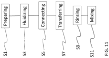
- Figure 11 is a flow chart of a method for transferring a slurry of a separation resin from at least one first container 3; 3'; 3a, 3b; 3a', 3b', 3c', 3d' to a second container 5, 5' according to one embodiment of the invention. The method steps are described below:
- the step of preparing, S1 comprises in one embodiment preparing two or more first containers and the step of fluidically connecting, S5, the outlet port of the at least one first container to an inlet port of the second container comprises in one embodiment connecting the outlet port of each first container to a resin transfer manifold in series or in parallel and connecting the resin transfer manifold to the inlet of the second container.
- the method can in one embodiment of the invention further comprise the steps of sterilizing the at least one first container comprising separation resin by gamma radiation and sterilizing an interior of the second container before the step of fluidically connecting the outlet port of the at least one first container to an inlet port of the second container, wherein fluidically connecting is performed by aseptic connections.
- Said mechanical interaction to the first container from an outside of the first container to provide a deformation of said first container can be performed by manual interaction or by a mechanical interaction device provided in a storage bin in which said first container is provided.
- the separation resin which initially is provided in the at least one first container 3; 3'; 3a, 3b; 3a', 3b'; 63 is transferred to the second container 5; 5' through the transferring connection 7; 7' without the separation resin being in contact with the vacuum production device 9; 9' during the transfer.
- the step of allowing the under-pressure/ vacuum provided in the second container 5; 5' to affect the content in the at least one first container 3; 3'; 3a, 3b; 3a', 3b'; 63 comprises opening a valve 11; 11' provided in the transferring connection 7; 7' between the at least one first container 3; 3'; 3a, 3b; 3a', 3b'; 63 and the second container 5; 5'.
- the method further comprises the optional step of: S9: Rinsing the at least one first container 3; 3'; 3a, 3b; 3a', 3b'; 63 in order to assure that substantially all separation resin will be transferred to the second container 5; 5'.
- the rinsing being accomplished by transferring a rinsing solution, which could be for example a buffer, through the at least one first container 3; 3'; 3a, 3b; 3a', 3b'; 63 and further to the second container 5; 5'.
- the step of rinsing the at least one first container 3; 3'; 3a, 3b; 3a', 3b'; 63 comprises opening a rinsing valve 31; 31' provided in the connection between the at least one first container 3; 3'; 3a, 3b; 3a', 3b'; 63 and the rinse bag 29; 29' to allow the under-pressure/vacuum provided to the second container 5; 5' to transfer rinsing solution from the rinse bag 29; 29' through the at least one first container 3; 3'; 3a, 3b; 3a', 3b'; 63 and finally to the second container 5; 5' and closing the rinse valve when a suitable amount of rinsing solution has been transferred.
- the method comprises connecting two or more first containers 3a, 3b; 3a', 3b' in series or in parallel to the second container 5; 5' allowing the content of all of the first containers 3a, 3b; 3a', 3b' to be transferred to the second container 5; 5'.
- the method further comprises the optional step of: S11: Mixing the separation resin slurry in the second container 5; 5'.
- S11 Mixing the separation resin slurry in the second container 5; 5'.
- the mixing of the slurry in the second container 5; 5' can be performed by fluidizing the slurry, for example from below as shown in Figures 5-8 .
- a connected liquid supply system could provide buffer or water to the second container 5, 5' and hereby the slurry can be mixed and homogenized.
- a method for aseptic packing of a chromatography column with a separation resin comprises the steps of:
- the transferring of the separation resin from the first container to the second container can be performed according to the method as described above in relation to Figure 11 .
Landscapes
- Chemical & Material Sciences (AREA)
- Health & Medical Sciences (AREA)
- Analytical Chemistry (AREA)
- Life Sciences & Earth Sciences (AREA)
- General Health & Medical Sciences (AREA)
- Pathology (AREA)
- Biochemistry (AREA)
- Physics & Mathematics (AREA)
- General Physics & Mathematics (AREA)
- Immunology (AREA)
- Chemical Kinetics & Catalysis (AREA)
- Animal Behavior & Ethology (AREA)
- Epidemiology (AREA)
- Public Health (AREA)
- Veterinary Medicine (AREA)
- Apparatus Associated With Microorganisms And Enzymes (AREA)
- Feeding, Discharge, Calcimining, Fusing, And Gas-Generation Devices (AREA)
- Treatment Of Liquids With Adsorbents In General (AREA)
- Basic Packing Technique (AREA)
- External Artificial Organs (AREA)
Claims (18)
- Procédé pour transférer une résine de séparation d'au moins un premier récipient (3 ; 3' ; 3a, 3b ; 3a', 3b', 3c', 3d') à un second récipient (5 ; 5'), dans lequel ledit premier récipient est un récipient de stockage de résine de séparation déformable à usage unique, ledit procédé comprenant les étapes consistant àpréparer (S1) le au moins un premier récipient en fournissant un récipient déformable à usage unique comprenant un orifice de sortie (4') avec un volume prédéfini de résine de séparation dans une solution de stockage ;fluidiser (S3) la résine de séparation dans le au moins un premier récipient pour fournir une suspension de résine, ladite fluidisation étant réalisée par une interaction mécanique avec le premier récipient depuis un extérieur du premier récipient pour produire une déformation dudit premier récipient ;raccorder fluidiquement (S5) l'orifice de sortie (4') du au moins un premier récipient à un orifice d'entrée (103) du second récipient ;transférer (S7) la résine de séparation du au moins un premier récipient au second récipient en générant une différence de pression entre un intérieur du second récipient et un intérieur du premier récipient dans lequel la pression est plus faible dans le second récipient,dans lequel un raccordement de transfert (7 ; 7') est prévu entre le au moins un premier récipient (3 ; 3' ; 3a, 3b ; 3a', 3b', 3c', 3d') et le second récipient (5 ; 5' ), ledit raccordement de transfert (7 ; 7') comprenant au moins une vanne (11 ; 11' ; 23a, 23b ; 23a', 23b').
- Procédé selon la revendication 1, dans lequel :a) l'étape de transfert (S7) d'une résine de séparation du au moins un premier récipient au second récipient comprend la génération d'une dépression dans le second récipient par rapport à la pression dans le premier récipient ;b) ledit second récipient (5 ; 5') est un dispositif de séparation ;c) l'étape de fluidisation (S3) comprend la fluidisation de la résine de séparation en une suspensiond) le procédé comprend en outre les étapes de stérilisation du au moins un premier récipient comprenant une résine de séparation par rayonnement gamma et de stérilisation d'un intérieur du second récipient avant l'étape de raccordement fluidique de l'orifice de sortie du au moins un premier récipient à un orifice d'entrée du second récipient, dans lequel le raccordement fluidique est réalisé par des raccordements aseptiques ; et/oue) le au moins un premier récipient comprenant une résine de séparation et le second récipient sont préstérilisés et l'étape de raccordement fluidique (S5) est réalisée par des raccordements aseptiques.
- Procédé selon l'une quelconque des revendications précédentes, dans lequel l'étape de préparation comprend la préparation de deux, ou plus, premiers récipients (3 ; 3' ; 3a, 3b ; 3a', 3b', 3c', 3d') et l'étape de raccordement fluidique de l'orifice de sortie du au moins un premier récipient à un orifice d'entrée du second récipient comprend le raccordement de l'orifice de sortie de chaque premier récipient à un collecteur de transfert de résine en série ou en parallèle et le raccordement du collecteur de transfert de résine à l'entrée du second récipient.
- Procédé selon l'une quelconque des revendications précédentes, dans lequel ladite fluidisation est réalisée par une interaction manuelle ou par un dispositif d'interaction mécanique (507a, 507b, 507c) depuis un extérieur du premier récipient pour provoquer une déformation dudit premier récipient, dans lequel ledit dispositif d'interaction mécanique est disposé dans un bac de stockage (509a, 509b, 509c) dans lequel ledit premier récipient est disposé.
- Procédé selon la revendication 4, dans lequel ladite fluidisation est réalisée en déplaçant une ou plusieurs parties inférieures mobiles (507a) d'un bac de stockage (509a), en gonflant/dégonflant un ou plusieurs coussins d'air gonflables (507b) disposés dans un bac de stockage (509b) ou en inclinant le premier récipient.
- Procédé selon l'une quelconque des revendications précédentes, dans lequel l'étape de transfert (S7) d'une résine de séparation du au moins un premier récipient au second récipient comprend :- la fourniture d'un degré de vide/dépression au second récipient (5 ; 5') par un dispositif de production de vide (9 ; 9') raccordé au second récipient (5 ; 5') ;- la permission donnée au vide/à la dépression dans le second récipient (5 ; 5') d'affecter le contenu dans le au moins un premier récipient (3 ; 3' ; 3a, 3b ; 3a', 3b', 3c', 3d') au moyen du raccordement de transfert (7 ; 7') qui raccorde fluidiquement le au moins un premier récipient au second récipient, de telle sorte que la résine de séparation disposée initialement dans le au moins un premier récipient (3 ; 3' ; 3a, 3b ; 3a', 3b', 3c', 3d') soit transférée au second récipient (5 ; 5') au moyen du raccordement de transfert (7 ; 7'),dans lequel, facultativement, l'étape de la permission donnée au vide/à la dépression dans le second récipient (5 ; 5') d'affecter le contenu dans le au moins un premier récipient (3 ; 3' ; 3a, 3b ; 3a', 3b', 3c', 3d') comprend l'ouverture de la au moins une vanne (11 ; 11' ; 23a, 23b ; 23a', 23b') disposée dans le raccordement de transfert (7 ; 7') entre le au moins un premier récipient (3 ; 3' ; 3a, 3b ; 3a', 3b', 3c', 3d') et le second récipient (5 ; 5').
- Procédé selon l'une quelconque des revendications précédentes, comprenant en outre l'étape consistant à :
rincer (S9) du au moins un premier récipient (3 ; 3' ; 3a, 3b ; 3a', 3b', 3c', 3d') en transférant une solution de rinçage à travers le au moins un premier récipient (3 ; 3' ; 3a, 3b ; 3a', 3b', 3c', 3d') et en outre au second récipient (5 ; 5'), ladite solution de rinçage venant d'une poche de rinçage (29 ; 29') raccordée à le moins un premier récipient (3 ; 3' ; 3a, 3b ; 3a', 3b', 3c', 3d'), ledit transfert d'une solution de rinçage étant accompli par la même différence de pression que celle générée entre un intérieur du second récipient et le premier récipient pour transférer la résine de séparation. - Procédé selon la revendication 7, dans lequel l'étape de rinçage (S9) du au moins un premier récipient (3 ; 3' ; 3a, 3b ; 3a', 3b', 3c', 3d') comprend l'ouverture d'une vanne de rinçage (31 ; 31') disposée dans le raccordement entre le au moins un premier récipient (3 ; 3' ; 3a, 3b ; 3a', 3b', 3c', 3d') et la poche de rinçage (29 ; 29') pour permettre à la différence de pression entre les premier et second récipients de transférer une solution de rinçage depuis la poche de rinçage (29 ; 29') à travers le au moins un premier récipient (3 ; 3' ; 3a, 3b ; 3a', 3b', 3c', 3d') et finalement au second récipient (5 ; 5') et la fermeture de la vanne de rinçage (31 ; 31') lorsqu'une quantité appropriée de solution de rinçage a été transférée.
- Procédé selon l'une quelconque des revendications précédentes, dans lequel :a) le procédé comprend en outre l'étape consistant à :
mélanger (511) la suspension de résine de séparation dans le second récipient (5 ; 5') en utilisant un système d'alimentation en liquide raccordé pour fluidiser la suspension de résine de séparation à l'intérieur du second récipient ;b) l'étape de transfert de résine de séparation du au moins un premier récipient au second récipient en générant une différence de pression entre un intérieur du second récipient et un intérieur du premier récipient comprend la commande d'un adaptateur disposé dans le second récipient (5') ; et/ouc) ledit au moins un premier récipient (3 ; 3' ; 3a, 3b ; 3a', 3b', 3c', 3d') est un sac souple. - Système pour transférer une résine de séparation entre au moins deux récipients, dans lequel ledit système comprend :au moins un système de récipient (505a, 505b, 505c), ledit système de récipient comprenant au moins un premier récipient (3 ; 3' ; 3a, 3b ; 3a', 3b', 3c', 3d') qui est un récipient de stockage de résine de séparation déformable à usage unique comprenant un volume prédéterminé de résine de séparation et un volume prédéterminé de solution de stockage, ledit premier récipient comprenant en outre un orifice de sortie agencé pour transférer la résine de séparation, ledit premier récipient étant facultativement un sac souple ; et- un dispositif d'interaction mécanique (507a, 507b, 507c) disposé en raccordement avec un extérieur du premier récipient de telle sorte qu'il puisse assurer une déformation dudit premier récipient ;un second récipient (5 ; 5'), qui est facultativement un dispositif de séparation, comprenant un orifice d'entrée qui est raccordé fluidiquement à l'orifice de sortie dudit au moins un premier récipient ; un raccordement de transfert (7 ; 7') disposé entre le au moins un premier récipient (3 ; 3' ; 3a, 3b ; 3a', 3b', 3c', 3d') et le second récipient (5 ; 5'), ledit raccordement de transfert (7 ; 7') comprenant au moins une vanne (11 ; 11' ; 23a, 23b; 23a', 23b') ;
etun dispositif de génération de différence de pression (9 ; 9') configuré pour transférer une résine de séparation du au moins un premier récipient (3 ; 3' ; 3a, 3b ; 3a', 3b', 3c', 3d') au second récipient ( 5; 5') en générant une différence de pression entre un intérieur du second récipient et un intérieur du premier récipient dans lequel la pression est plus faible dans le second récipient ; etdans lequel, facultativement, ledit dispositif de génération de différence de pression (9 ; 9') est un dispositif de génération de dépression (9 ; 9') configuré pour transférer une résine de séparation du au moins un premier récipient au second récipient en générant une dépression dans le second récipient par rapport à la pression dans le premier récipient. - Système selon la revendication 10, dans lequel ledit dispositif d'interaction mécanique (507a, 507b, 507c) est disposé dans un bac de stockage (509a, 509b, 509c) dans lequel ledit premier récipient (3 ; 3' ; 3a, 3b ; 3a', 3b', 3c', 3d') est disposé, dans lequel, facultativement, ledit dispositif d'interaction mécanique est un ou plusieurs d'au moins une partie inférieure ou latérale mobile (507b) dans le bac de stockage (509b), d'au moins un coussin d'air gonflable (507a ) à l'intérieur du bac de stockage (509a) et d'un dispositif d'inclinaison (507c) pour incliner le bac de stockage (509c).
- Système selon la revendication 10 ou 11, dans lequel le système comprend deux, ou plus, premiers récipients (3a', 3b', 3c', 3d') raccordés en série ou en parallèle et qui sont raccordés fluidiquement au second récipient (5').
- Système selon la revendication 12, dans lequel les orifices de sortie des deux, ou plus, premiers récipients sont raccordés à un collecteur de transfert de résine qui, à son tour, est raccordé à l'entrée du second récipient.
- Système selon l'une quelconque des revendications 10-13, dans lequel ledit dispositif de génération de différence de pression (9 ; 9') est au moins un dispositif de génération de dépression/dispositif de production de vide (9 ; 9') raccordé au second récipient (5 ; 5') et agencé pour fournir un degré de vide/dépression dans le second récipient (5 ; 5') au moins pendant un transfert de la résine de séparation du au moins un premier récipient (3 ; 3' ; 3a, 3b ; 3a', 3b', 3c', 3d') au second récipient (5; 5') et dans lequel le au moins un premier récipient est raccordé au second récipient par le raccordement de transfert (7 ; 7'), comprenant facultativement des pièces de raccordement préstérilisées jetables de telle sorte que la résine de séparation initialement disposée dans le au moins un premier récipient (3 ; 3' ; 3a, 3b ; 3a', 3b', 3c', 3d') puisse être transférée du au moins un premier récipient (3 ; 3' ; 3a, 3b ; 3a', 3b', 3c', 3d') au second récipient (5 ; 5') au moyen du raccordement de transfert (7 ; 7') par le vide/la dépression fourni au second récipient (5 ; 5').
- Système selon la revendication 14, selon lequel une ouverture de la au moins une vanne (11 ; 11' ; 23a, 23b ; 23a' ; 23b') permet au vide/à la dépression fourni au second récipient (5 ; 5') d'affecter le contenu dans le premier récipient (3 ; 3' ; 3a, 3b ; 3a', 3b', 3c', 3d') de telle sorte que la résine de séparation disposée initialement dans le premier récipient (3 ; 3' ; 3a, 3b ; 3a', 3b', 3c', 3d') soit transférée au second récipient (5 ; 5') au moyen du raccordement de transfert (7 ; 7').
- Système selon l'une quelconque des revendications 12-15, dans lequel le système comprend en outre une poche de rinçage (29 ; 29') raccordée au premier récipient (3 ; 3' ; 3a, 3b ; 3a', 3b', 3c', 3d'), ladite poche de rinçage (29 ; 29') comprenant une solution de rinçage pour rincer le premier récipient (3 ; 3' ; 3a, 3b ; 3a', 3b', 3c', 3d') lorsque la résine de séparation a été transférée au second récipient (5 ; 5'), ladite solution de rinçage étant transférée de la poche de rinçage (29 ; 29') au premier récipient (3 ; 3' ; 3a, 3b ; 3a', 3b', 3c', 3d') par la même différence de pression que celle générée entre un intérieur du second récipient et le premier récipient pour transférer la résine de séparation.
- Système selon la revendication 16, dans lequel une vanne de rinçage (31 ; 31') est disposée entre la poche de rinçage (29 ; 29') et le au moins un premier récipient (3 ; 3' ; 3a, 3b ; 3a', 3b', 3c', 3d') de telle sorte qu'une solution de rinçage soit transférée de la poche de rinçage (29 ; 29') à le au moins un premier récipient (3 ; 3' ; 3a, 3b ; 3a', 3b', 3c', 3d') par la différence de pression générée entre les premier et second récipients lorsque la vanne de rinçage (31 ; 31') est ouverte.
- Système selon l'une quelconque des revendications 12-17, dans lequel :a) le second récipient (5 ; 5') est une colonne de chromatographie raccordée à un système d'alimentation en liquide (111) de telle sorte que la résine de séparation puisse être fluidisée à l'intérieur du second récipient (5 ; 5') par le système d'alimentation en liquide (111), dans lequel le second récipient (5 ; 5') comprend facultativement un système de distribution de liquide (107) au niveau d'une entrée (109) pour le système d'alimentation en liquide (111), ce qui permet d'améliorer une homogénéisation de la suspension fournie par la fluidisation ;b) le second récipient (5 ; 5') comprend un adaptateur (105) définissant le volume interne du second récipient (5 ; 5') conjointement avec un fond et des parois internes du second récipient, lequel adaptateur (105) peut être utilisé comme dispositif de génération de différence de pression (9') en le soulevant à l'intérieur du second récipient (5 ; 5'), ce qui permet d'augmenter le volume interne du second récipient (5 ; 5') ; et/ouc) ledit au moins un premier récipient (3 ; 3' ; 3a, 3b ; 3a', 3b', 3c', 3d') est un sac souple.
Applications Claiming Priority (2)
| Application Number | Priority Date | Filing Date | Title |
|---|---|---|---|
| GBGB1701576.9A GB201701576D0 (en) | 2017-01-31 | 2017-01-31 | Method and system for transferring separation resin |
| PCT/EP2018/052187 WO2018141701A1 (fr) | 2017-01-31 | 2018-01-30 | Procédé et système permettant de transférer une résine de séparation |
Publications (2)
| Publication Number | Publication Date |
|---|---|
| EP3576859A1 EP3576859A1 (fr) | 2019-12-11 |
| EP3576859B1 true EP3576859B1 (fr) | 2024-08-14 |
Family
ID=58462864
Family Applications (1)
| Application Number | Title | Priority Date | Filing Date |
|---|---|---|---|
| EP18704897.0A Active EP3576859B1 (fr) | 2017-01-31 | 2018-01-30 | Procédé et système permettant de transférer une résine de séparation |
Country Status (5)
| Country | Link |
|---|---|
| US (2) | US11291929B2 (fr) |
| EP (1) | EP3576859B1 (fr) |
| CN (1) | CN110214043B (fr) |
| GB (1) | GB201701576D0 (fr) |
| WO (1) | WO2018141701A1 (fr) |
Families Citing this family (1)
| Publication number | Priority date | Publication date | Assignee | Title |
|---|---|---|---|---|
| EP4000642A1 (fr) * | 2020-11-16 | 2022-05-25 | Sartorius Stedim Biotech GmbH | Procédé de maintien de la pureté microbiologique d'un dispositif jetable ainsi que couvercle pour un raccordement de fluide d'une unité de séparation destinée à l'utilisation dans un tel procédé |
Family Cites Families (83)
| Publication number | Priority date | Publication date | Assignee | Title |
|---|---|---|---|---|
| US626950A (en) | 1899-06-13 | Island | ||
| US2006393A (en) | 1933-03-16 | 1935-07-02 | Laval Separator Co De | Apparatus for delivering milk to cans |
| DE629833C (de) | 1933-03-29 | 1936-05-14 | Naamlooze Vennootschap Machine | Verfahren zum Umfuellen von verfluessigten, brennbaren Gasen |
| FR1124356A (fr) * | 1954-05-22 | 1956-10-09 | Dispositif de prise et de conservation des liquides biologiques, tels que le sang, les sérums, les solutions d'injection et liquides analogues | |
| US2982247A (en) | 1958-07-23 | 1961-05-02 | Craft Mfg Company | Sealed dairy milk transfer tank |
| US3078847A (en) | 1959-05-06 | 1963-02-26 | Baxter Laboratories Inc | Blood handling method and apparatus |
| NL102903C (fr) | 1959-09-25 | |||
| US3863664A (en) | 1969-11-13 | 1975-02-04 | Medical Dev Corp | Vacuum-operated fluid bottles in serial flow system |
| JPS5231610B1 (fr) | 1969-11-14 | 1977-08-16 | ||
| US4045004A (en) | 1976-10-01 | 1977-08-30 | Berger Henry F | Chemical mixing and pumping apparatus |
| US4195672A (en) * | 1978-05-24 | 1980-04-01 | Freeman James F | Portable liquid pesticide transfer assembly |
| US4250035A (en) * | 1978-11-13 | 1981-02-10 | Waters Associates, Inc. | Radial compression of packed beds |
| US4263144A (en) | 1979-12-10 | 1981-04-21 | The United States Of America As Represented By The Secretary Of Agriculture | Device for collecting and transferring particulate material |
| US4467915A (en) * | 1980-08-20 | 1984-08-28 | Snyder Robert G | Emulsion package and method of mixing the emulsion |
| US4388922A (en) * | 1981-07-29 | 1983-06-21 | Becton, Dickinson And Company | Suction canister system for serial collection of fluids |
| WO1990011963A1 (fr) * | 1989-04-06 | 1990-10-18 | James Lionel Nelson | Appareil distributeur |
| US5213683A (en) * | 1991-08-08 | 1993-05-25 | Chromaflow, Inc. | Apparatus for charging and discharging of chromatography column bed |
| NZ269756A (en) | 1993-07-23 | 1997-10-24 | Kevin Johan Fuchsbichler | Dissolving solid in liquid: solution recirculated so as to produce circular flow in solution vessel. |
| US5876511A (en) | 1994-02-02 | 1999-03-02 | Gea Till Gmbh & Co. | Method for cleaning and rinsing containers |
| US5423982A (en) | 1994-05-31 | 1995-06-13 | Biosepra Inc. | Liquid chromatography column adapted for in situ chemical sterilization |
| JP3395410B2 (ja) | 1994-11-07 | 2003-04-14 | 栗田工業株式会社 | 液体クロマトグラフィー用カラムの充填方法 |
| US5875925A (en) | 1994-12-20 | 1999-03-02 | Stevens Eva Josephine | Methods and apparatus for transferring hazardous liquids |
| DE19749939C2 (de) | 1997-11-11 | 2003-10-23 | Boehringer Werkzeugmaschinen | Verfahren zur Bearbeitung von Werkstücken |
| GB9812344D0 (en) * | 1998-06-08 | 1998-08-05 | Euroflow Uk Ltd | Methods and apparatus for packing chromatography columns |
| JP3437458B2 (ja) * | 1998-09-10 | 2003-08-18 | キユーピー株式会社 | ダブルバッグの液体充填方法とその装置およびその装置に用いるバッグの半折装置 |
| EP1181237A1 (fr) | 1998-10-12 | 2002-02-27 | Stevens Nominees (QLD) Pty. Ltd. | Appareil de transfert de liquides et adaptateurs |
| GB2344543B (en) * | 1998-12-10 | 2002-11-27 | Millipore Corp | Chromatography column system and method of packing a chromatography system |
| JP2000205900A (ja) | 1999-01-18 | 2000-07-28 | Mitsubishi Paper Mills Ltd | 流量モニタ― |
| JP2001070785A (ja) * | 1999-09-03 | 2001-03-21 | Keiji Komine | 粒状吸液材 |
| US6402958B1 (en) * | 2000-08-17 | 2002-06-11 | Uop Llc | Chromatography column loading method |
| JP4879392B2 (ja) * | 2000-11-09 | 2012-02-22 | 日本錬水株式会社 | クロマト分離方法 |
| US6544788B2 (en) * | 2001-02-15 | 2003-04-08 | Vijay Singh | Disposable perfusion bioreactor for cell culture |
| DE10119334C1 (de) | 2001-04-20 | 2002-03-14 | Porsche Ag | Reibungskupplung |
| US20050242018A1 (en) | 2001-08-01 | 2005-11-03 | Teledyne Isco, Inc. | Disposable chromatographic columns |
| EP1348957A1 (fr) | 2002-03-27 | 2003-10-01 | Büchi Labortechnik AG | Appareil et procédé pour remplir une colonne par un matériel remplissant |
| DE60311981T2 (de) * | 2002-04-26 | 2007-09-06 | Navigant Biotechnologies, Inc., Lakewood | Vorrichtung zur bestrahlung und mischung von fluiden in behältern |
| US9283521B2 (en) * | 2002-06-14 | 2016-03-15 | Parker-Hannifin Corporation | Single-use manifold and sensors for automated, aseptic transfer of solutions in bioprocessing applications |
| FR2851242B1 (fr) * | 2003-02-13 | 2005-10-21 | Rhodia Chimie Sa | Procede de vidange d'un conteneur souple renfermant un produit visqueux |
| JP3490432B1 (ja) | 2003-05-30 | 2004-01-26 | 株式会社日清製粉グループ本社 | 液体クロマトグラフィー用カラムの充填方法 |
| US20040245124A1 (en) * | 2003-06-03 | 2004-12-09 | Hurst William E. | Preformed mixing bag for dry powder, apparatus, method and system for using same |
| US7377686B2 (en) * | 2003-09-04 | 2008-05-27 | Millipore Corporation | Disposable mixing system |
| CA2552310A1 (fr) * | 2004-01-07 | 2005-07-28 | Walker-Dawson Interests, Inc. | Systeme de contenant sous vide et procede associe |
| FR2866321B1 (fr) | 2004-02-13 | 2007-05-18 | Lablabo | Poche souple deformable et dispositif pour le conditionnement et la distribution de produits fluides. |
| EP1566631A1 (fr) * | 2004-02-23 | 2005-08-24 | Bio-Rad Pasteur | Procédé et dispositif pour chargement à sec des résines chromatographiques |
| FR2880339A1 (fr) * | 2004-12-31 | 2006-07-07 | Rhodia Chimie Sa | Procede de conditionnement d'un conteneur souple renfermant un produit visqueux |
| US7682823B1 (en) * | 2005-01-04 | 2010-03-23 | Larry Runyon | Bioreactor systems |
| US7452471B2 (en) * | 2005-10-21 | 2008-11-18 | Ge Healthcare Bio-Sciences Ab | Automated packing system and method for chromatography columns |
| US20070215548A1 (en) * | 2006-01-05 | 2007-09-20 | Zhou Joe Xin H | Systems and methods for packing chromatography columns |
| GB0614316D0 (en) * | 2006-07-19 | 2006-08-30 | Ge Healthcare Bio Sciences Ab | Axial Chromatography Columns and Methods |
| US8272776B2 (en) | 2007-01-31 | 2012-09-25 | Ge Healthcare Bio-Sciences Ab | Method and apparatus for forming an homogeneous mixture of chromatography media in a vessel |
| US8070354B2 (en) * | 2007-02-05 | 2011-12-06 | Bungay Iii Henry Robert | Systems and methods for mixing bioprocessing materials |
| US9597611B2 (en) * | 2007-03-09 | 2017-03-21 | Ge Healthcare Bioprocess R&D Ab | Packing system and method for chromatography columns |
| GB0704603D0 (en) * | 2007-03-09 | 2007-04-18 | Ge Healthcare Bio Sciences Ab | Packing system and method for chromatography columns |
| DE102007026549A1 (de) * | 2007-06-08 | 2008-12-11 | Bayer Materialscience Ag | Verfahren zum Umfüllen von vorkonditionierten Ionenaustauscherharz-Suspensionen |
| US8117901B2 (en) | 2007-07-06 | 2012-02-21 | Ge Healthcare Bio-Sciences Ab | Determination of slurry concentration |
| US9109193B2 (en) * | 2007-07-30 | 2015-08-18 | Ge Healthcare Bio-Sciences Corp. | Continuous perfusion bioreactor system |
| WO2009032903A1 (fr) * | 2007-09-04 | 2009-03-12 | Q Labtech Llc | Appareil chromatographique et procédé |
| ES2679672T3 (es) | 2008-01-23 | 2018-08-30 | Ge Healthcare Bio-Sciences Ab | Método de empaquetamiento en columna |
| US20090188211A1 (en) * | 2008-01-25 | 2009-07-30 | Xcellerex, Inc. | Bag wrinkle remover, leak detection systems, and electromagnetic agitation for liquid containment systems |
| DE102008021349A1 (de) * | 2008-04-29 | 2009-11-05 | Osram Gesellschaft mit beschränkter Haftung | Elektrodengestell für eine Entladungslampe und Verfahren zum Herstellen eines Elektrodengestells sowie Entladungslampe |
| JP5675593B2 (ja) | 2008-05-30 | 2015-02-25 | ジーイー・ヘルスケア・バイオサイエンス・アクチボラグ | 自動式カラムパッキング方法 |
| CA2724870C (fr) * | 2008-05-30 | 2017-09-12 | Ge Healthcare Bio-Sciences Ab | Procede de remplissage de colonne |
| KR100962369B1 (ko) | 2008-06-26 | 2010-06-10 | 삼성전기주식회사 | 인쇄회로기판 및 그 제조방법 |
| CA2728319C (fr) | 2008-06-27 | 2016-11-08 | Ge Healthcare Bio-Sciences Ab | Cuve de suspension de milieu de separation |
| US20100243670A1 (en) * | 2009-03-24 | 2010-09-30 | Ferro Corporation | Methods and products for replenishing a polishing slurry in a polishing apparatus |
| CN101549217B (zh) * | 2009-04-17 | 2014-05-28 | 天津博纳艾杰尔科技有限公司 | 生物体液样品中的药物提取装置与方法 |
| TW201038334A (en) * | 2009-04-28 | 2010-11-01 | Singwei Technologies Co Ltd | Resin replacement device |
| KR101107169B1 (ko) * | 2009-08-26 | 2012-01-25 | 삼성모바일디스플레이주식회사 | 수지 유체 디스펜싱 장치 |
| GB0922426D0 (en) * | 2009-12-22 | 2010-02-03 | Ge Healthcare Bio Sciences Ab | Containers for chromatography media |
| US20140224738A1 (en) * | 2009-12-22 | 2014-08-14 | Ge Healthcare Bio-Sciences Ab | Packing of chromatography columns |
| US20110259831A1 (en) * | 2010-04-22 | 2011-10-27 | Michael Brandt | Tracking regulator system and method for processing columns |
| CN102275670A (zh) * | 2010-06-11 | 2011-12-14 | 沃哈商会有限公司 | 挤压装置及黏稠液体包装袋 |
| CN103270410A (zh) * | 2010-09-23 | 2013-08-28 | 艾克塞勒雷克斯公司 | 单次使用的制浆和色谱分析系统 |
| JP5630299B2 (ja) | 2011-02-02 | 2014-11-26 | 栗田工業株式会社 | 液体クロマトグラフィー装置及び充填剤の充填方法 |
| US8668886B2 (en) * | 2011-04-24 | 2014-03-11 | Therapeutic Proteins International, LLC | Separative bioreactor |
| CN202155132U (zh) | 2011-06-13 | 2012-03-07 | 江苏双江石化制品有限公司 | 固定床吸附剂真空填充装置 |
| US9284346B2 (en) * | 2011-09-07 | 2016-03-15 | Therapeutic Proteins International, LLC | Preparative chromatography column and methods |
| US9327213B2 (en) * | 2012-02-22 | 2016-05-03 | Bio-Rad Laboratories, Inc. | Preparative chromatography column |
| JP6461930B2 (ja) * | 2013-09-30 | 2019-01-30 | ジーイー・ヘルスケア・バイオサイエンス・アクチボラグ | スラリーの移送法 |
| FR3016794B1 (fr) | 2014-01-24 | 2018-03-02 | Pierre Fabre Dermo-Cosmetique | Dispositif et procede pour le transfert d'un produit sterile entre deux conteneurs |
| CN204841030U (zh) | 2015-08-10 | 2015-12-09 | 山西省交通科学研究院 | 一种填充色谱柱制备装置 |
| EP3487468B1 (fr) | 2016-07-25 | 2025-10-01 | ICU Medical, Inc. | Systèmes et composants pour piéger des bulles d'air dans des modules et des systèmes de transfert de fluide médical. |
| WO2018060496A1 (fr) * | 2016-09-30 | 2018-04-05 | Ge Healthcare Bio-Sciences Ab | Procédé et système permettant de transférer une résine de separation |
-
2017
- 2017-01-31 GB GBGB1701576.9A patent/GB201701576D0/en not_active Ceased
-
2018
- 2018-01-30 EP EP18704897.0A patent/EP3576859B1/fr active Active
- 2018-01-30 CN CN201880009331.8A patent/CN110214043B/zh active Active
- 2018-01-30 WO PCT/EP2018/052187 patent/WO2018141701A1/fr not_active Ceased
- 2018-01-30 US US16/481,655 patent/US11291929B2/en active Active
-
2022
- 2022-03-03 US US17/686,157 patent/US20220184527A1/en active Pending
Also Published As
| Publication number | Publication date |
|---|---|
| US11291929B2 (en) | 2022-04-05 |
| CN110214043B (zh) | 2022-03-01 |
| GB201701576D0 (en) | 2017-03-15 |
| CN110214043A (zh) | 2019-09-06 |
| US20200001204A1 (en) | 2020-01-02 |
| EP3576859A1 (fr) | 2019-12-11 |
| WO2018141701A1 (fr) | 2018-08-09 |
| US20220184527A1 (en) | 2022-06-16 |
Similar Documents
| Publication | Publication Date | Title |
|---|---|---|
| US20230333098A1 (en) | Method and System for Separating Biomolecules | |
| JP3616012B2 (ja) | クロマトグラフィーカラム系およびクロマトグラフィーカラムの充填方法 | |
| JP7035070B2 (ja) | 細胞培養装置システムおよびその使用の方法 | |
| US11141681B2 (en) | Packing system and method for chromatography columns | |
| CN102933285A (zh) | 用于生物液体处理设备的装置 | |
| US9597610B2 (en) | Packing system and method for chromatography columns | |
| US20220184527A1 (en) | Method and System for Transferring Separation Resin | |
| US7682505B2 (en) | Method and devices for dry loading of chromatography resins | |
| CN102077087B (zh) | 分离介质浆料罐 | |
| DE102017120686A1 (de) | Behälter und vorrichtung zum dosieren flüssiger medien | |
| EP2928800B1 (fr) | Appareil et procédé de transfert et de pressurisation de poudre | |
| EP3519072B1 (fr) | Procédé et système permettant de transférer une résine de separation | |
| CN107849507B (zh) | 用于将细胞与微载体分离的方法和设备 | |
| HK40011644A (en) | Method and system for transferring separation resin | |
| HK40011644B (en) | Method and system for transferring separation resin | |
| JPWO2018142923A1 (ja) | 分注装置及び液体移送方法 | |
| CN103958660A (zh) | 用于细胞分离的系统和方法 | |
| EP3790983B1 (fr) | Système et procédé de clarification d'une solution de récolte de culture cellulaire | |
| CN115715319A (zh) | 生物制药工艺用智能罐 | |
| US10358882B2 (en) | Continuous vacuum transport system and method | |
| JP2023553802A (ja) | バイオプロダクト処理装置 | |
| HK1249763B (en) | Methods and apparatus for separating cells from microcarriers |
Legal Events
| Date | Code | Title | Description |
|---|---|---|---|
| STAA | Information on the status of an ep patent application or granted ep patent |
Free format text: STATUS: UNKNOWN |
|
| STAA | Information on the status of an ep patent application or granted ep patent |
Free format text: STATUS: THE INTERNATIONAL PUBLICATION HAS BEEN MADE |
|
| PUAI | Public reference made under article 153(3) epc to a published international application that has entered the european phase |
Free format text: ORIGINAL CODE: 0009012 |
|
| STAA | Information on the status of an ep patent application or granted ep patent |
Free format text: STATUS: REQUEST FOR EXAMINATION WAS MADE |
|
| 17P | Request for examination filed |
Effective date: 20190723 |
|
| AK | Designated contracting states |
Kind code of ref document: A1 Designated state(s): AL AT BE BG CH CY CZ DE DK EE ES FI FR GB GR HR HU IE IS IT LI LT LU LV MC MK MT NL NO PL PT RO RS SE SI SK SM TR |
|
| AX | Request for extension of the european patent |
Extension state: BA ME |
|
| DAV | Request for validation of the european patent (deleted) | ||
| DAX | Request for extension of the european patent (deleted) | ||
| RAP1 | Party data changed (applicant data changed or rights of an application transferred) |
Owner name: CYTIVA SWEDEN AB |
|
| STAA | Information on the status of an ep patent application or granted ep patent |
Free format text: STATUS: EXAMINATION IS IN PROGRESS |
|
| 17Q | First examination report despatched |
Effective date: 20221017 |
|
| P01 | Opt-out of the competence of the unified patent court (upc) registered |
Effective date: 20230526 |
|
| GRAP | Despatch of communication of intention to grant a patent |
Free format text: ORIGINAL CODE: EPIDOSNIGR1 |
|
| STAA | Information on the status of an ep patent application or granted ep patent |
Free format text: STATUS: GRANT OF PATENT IS INTENDED |
|
| INTG | Intention to grant announced |
Effective date: 20240517 |
|
| GRAS | Grant fee paid |
Free format text: ORIGINAL CODE: EPIDOSNIGR3 |
|
| GRAA | (expected) grant |
Free format text: ORIGINAL CODE: 0009210 |
|
| STAA | Information on the status of an ep patent application or granted ep patent |
Free format text: STATUS: THE PATENT HAS BEEN GRANTED |
|
| AK | Designated contracting states |
Kind code of ref document: B1 Designated state(s): AL AT BE BG CH CY CZ DE DK EE ES FI FR GB GR HR HU IE IS IT LI LT LU LV MC MK MT NL NO PL PT RO RS SE SI SK SM TR |
|
| REG | Reference to a national code |
Ref country code: GB Ref legal event code: FG4D |
|
| REG | Reference to a national code |
Ref country code: CH Ref legal event code: EP |
|
| REG | Reference to a national code |
Ref country code: DE Ref legal event code: R096 Ref document number: 602018073035 Country of ref document: DE |
|
| REG | Reference to a national code |
Ref country code: IE Ref legal event code: FG4D |
|
| REG | Reference to a national code |
Ref country code: SE Ref legal event code: TRGR |
|
| REG | Reference to a national code |
Ref country code: LT Ref legal event code: MG9D |
|
| PG25 | Lapsed in a contracting state [announced via postgrant information from national office to epo] |
Ref country code: NO Free format text: LAPSE BECAUSE OF FAILURE TO SUBMIT A TRANSLATION OF THE DESCRIPTION OR TO PAY THE FEE WITHIN THE PRESCRIBED TIME-LIMIT Effective date: 20241114 |
|
| REG | Reference to a national code |
Ref country code: AT Ref legal event code: MK05 Ref document number: 1712765 Country of ref document: AT Kind code of ref document: T Effective date: 20240814 |
|
| PG25 | Lapsed in a contracting state [announced via postgrant information from national office to epo] |
Ref country code: PT Free format text: LAPSE BECAUSE OF FAILURE TO SUBMIT A TRANSLATION OF THE DESCRIPTION OR TO PAY THE FEE WITHIN THE PRESCRIBED TIME-LIMIT Effective date: 20241216 Ref country code: PL Free format text: LAPSE BECAUSE OF FAILURE TO SUBMIT A TRANSLATION OF THE DESCRIPTION OR TO PAY THE FEE WITHIN THE PRESCRIBED TIME-LIMIT Effective date: 20240814 Ref country code: GR Free format text: LAPSE BECAUSE OF FAILURE TO SUBMIT A TRANSLATION OF THE DESCRIPTION OR TO PAY THE FEE WITHIN THE PRESCRIBED TIME-LIMIT Effective date: 20241115 Ref country code: FI Free format text: LAPSE BECAUSE OF FAILURE TO SUBMIT A TRANSLATION OF THE DESCRIPTION OR TO PAY THE FEE WITHIN THE PRESCRIBED TIME-LIMIT Effective date: 20240814 |
|
| PG25 | Lapsed in a contracting state [announced via postgrant information from national office to epo] |
Ref country code: BG Free format text: LAPSE BECAUSE OF FAILURE TO SUBMIT A TRANSLATION OF THE DESCRIPTION OR TO PAY THE FEE WITHIN THE PRESCRIBED TIME-LIMIT Effective date: 20240814 |
|
| PG25 | Lapsed in a contracting state [announced via postgrant information from national office to epo] |
Ref country code: LV Free format text: LAPSE BECAUSE OF FAILURE TO SUBMIT A TRANSLATION OF THE DESCRIPTION OR TO PAY THE FEE WITHIN THE PRESCRIBED TIME-LIMIT Effective date: 20240814 |
|
| PG25 | Lapsed in a contracting state [announced via postgrant information from national office to epo] |
Ref country code: AT Free format text: LAPSE BECAUSE OF FAILURE TO SUBMIT A TRANSLATION OF THE DESCRIPTION OR TO PAY THE FEE WITHIN THE PRESCRIBED TIME-LIMIT Effective date: 20240814 Ref country code: IS Free format text: LAPSE BECAUSE OF FAILURE TO SUBMIT A TRANSLATION OF THE DESCRIPTION OR TO PAY THE FEE WITHIN THE PRESCRIBED TIME-LIMIT Effective date: 20241214 |
|
| PG25 | Lapsed in a contracting state [announced via postgrant information from national office to epo] |
Ref country code: HR Free format text: LAPSE BECAUSE OF FAILURE TO SUBMIT A TRANSLATION OF THE DESCRIPTION OR TO PAY THE FEE WITHIN THE PRESCRIBED TIME-LIMIT Effective date: 20240814 |
|
| PG25 | Lapsed in a contracting state [announced via postgrant information from national office to epo] |
Ref country code: ES Free format text: LAPSE BECAUSE OF FAILURE TO SUBMIT A TRANSLATION OF THE DESCRIPTION OR TO PAY THE FEE WITHIN THE PRESCRIBED TIME-LIMIT Effective date: 20240814 Ref country code: RS Free format text: LAPSE BECAUSE OF FAILURE TO SUBMIT A TRANSLATION OF THE DESCRIPTION OR TO PAY THE FEE WITHIN THE PRESCRIBED TIME-LIMIT Effective date: 20241114 |
|
| PG25 | Lapsed in a contracting state [announced via postgrant information from national office to epo] |
Ref country code: RS Free format text: LAPSE BECAUSE OF FAILURE TO SUBMIT A TRANSLATION OF THE DESCRIPTION OR TO PAY THE FEE WITHIN THE PRESCRIBED TIME-LIMIT Effective date: 20241114 Ref country code: PT Free format text: LAPSE BECAUSE OF FAILURE TO SUBMIT A TRANSLATION OF THE DESCRIPTION OR TO PAY THE FEE WITHIN THE PRESCRIBED TIME-LIMIT Effective date: 20241216 Ref country code: PL Free format text: LAPSE BECAUSE OF FAILURE TO SUBMIT A TRANSLATION OF THE DESCRIPTION OR TO PAY THE FEE WITHIN THE PRESCRIBED TIME-LIMIT Effective date: 20240814 Ref country code: NO Free format text: LAPSE BECAUSE OF FAILURE TO SUBMIT A TRANSLATION OF THE DESCRIPTION OR TO PAY THE FEE WITHIN THE PRESCRIBED TIME-LIMIT Effective date: 20241114 Ref country code: LV Free format text: LAPSE BECAUSE OF FAILURE TO SUBMIT A TRANSLATION OF THE DESCRIPTION OR TO PAY THE FEE WITHIN THE PRESCRIBED TIME-LIMIT Effective date: 20240814 Ref country code: IS Free format text: LAPSE BECAUSE OF FAILURE TO SUBMIT A TRANSLATION OF THE DESCRIPTION OR TO PAY THE FEE WITHIN THE PRESCRIBED TIME-LIMIT Effective date: 20241214 Ref country code: HR Free format text: LAPSE BECAUSE OF FAILURE TO SUBMIT A TRANSLATION OF THE DESCRIPTION OR TO PAY THE FEE WITHIN THE PRESCRIBED TIME-LIMIT Effective date: 20240814 Ref country code: GR Free format text: LAPSE BECAUSE OF FAILURE TO SUBMIT A TRANSLATION OF THE DESCRIPTION OR TO PAY THE FEE WITHIN THE PRESCRIBED TIME-LIMIT Effective date: 20241115 Ref country code: FI Free format text: LAPSE BECAUSE OF FAILURE TO SUBMIT A TRANSLATION OF THE DESCRIPTION OR TO PAY THE FEE WITHIN THE PRESCRIBED TIME-LIMIT Effective date: 20240814 Ref country code: ES Free format text: LAPSE BECAUSE OF FAILURE TO SUBMIT A TRANSLATION OF THE DESCRIPTION OR TO PAY THE FEE WITHIN THE PRESCRIBED TIME-LIMIT Effective date: 20240814 Ref country code: BG Free format text: LAPSE BECAUSE OF FAILURE TO SUBMIT A TRANSLATION OF THE DESCRIPTION OR TO PAY THE FEE WITHIN THE PRESCRIBED TIME-LIMIT Effective date: 20240814 Ref country code: AT Free format text: LAPSE BECAUSE OF FAILURE TO SUBMIT A TRANSLATION OF THE DESCRIPTION OR TO PAY THE FEE WITHIN THE PRESCRIBED TIME-LIMIT Effective date: 20240814 |
|
| PG25 | Lapsed in a contracting state [announced via postgrant information from national office to epo] |
Ref country code: DK Free format text: LAPSE BECAUSE OF FAILURE TO SUBMIT A TRANSLATION OF THE DESCRIPTION OR TO PAY THE FEE WITHIN THE PRESCRIBED TIME-LIMIT Effective date: 20240814 Ref country code: RO Free format text: LAPSE BECAUSE OF FAILURE TO SUBMIT A TRANSLATION OF THE DESCRIPTION OR TO PAY THE FEE WITHIN THE PRESCRIBED TIME-LIMIT Effective date: 20240814 Ref country code: SM Free format text: LAPSE BECAUSE OF FAILURE TO SUBMIT A TRANSLATION OF THE DESCRIPTION OR TO PAY THE FEE WITHIN THE PRESCRIBED TIME-LIMIT Effective date: 20240814 |
|
| PG25 | Lapsed in a contracting state [announced via postgrant information from national office to epo] |
Ref country code: EE Free format text: LAPSE BECAUSE OF FAILURE TO SUBMIT A TRANSLATION OF THE DESCRIPTION OR TO PAY THE FEE WITHIN THE PRESCRIBED TIME-LIMIT Effective date: 20240814 |
|
| PG25 | Lapsed in a contracting state [announced via postgrant information from national office to epo] |
Ref country code: CZ Free format text: LAPSE BECAUSE OF FAILURE TO SUBMIT A TRANSLATION OF THE DESCRIPTION OR TO PAY THE FEE WITHIN THE PRESCRIBED TIME-LIMIT Effective date: 20240814 |
|
| PG25 | Lapsed in a contracting state [announced via postgrant information from national office to epo] |
Ref country code: SK Free format text: LAPSE BECAUSE OF FAILURE TO SUBMIT A TRANSLATION OF THE DESCRIPTION OR TO PAY THE FEE WITHIN THE PRESCRIBED TIME-LIMIT Effective date: 20240814 Ref country code: IT Free format text: LAPSE BECAUSE OF FAILURE TO SUBMIT A TRANSLATION OF THE DESCRIPTION OR TO PAY THE FEE WITHIN THE PRESCRIBED TIME-LIMIT Effective date: 20240814 |
|
| REG | Reference to a national code |
Ref country code: DE Ref legal event code: R097 Ref document number: 602018073035 Country of ref document: DE |
|
| PLBE | No opposition filed within time limit |
Free format text: ORIGINAL CODE: 0009261 |
|
| STAA | Information on the status of an ep patent application or granted ep patent |
Free format text: STATUS: NO OPPOSITION FILED WITHIN TIME LIMIT |
|
| 26N | No opposition filed |
Effective date: 20250515 |
|
| PG25 | Lapsed in a contracting state [announced via postgrant information from national office to epo] |
Ref country code: MC Free format text: LAPSE BECAUSE OF FAILURE TO SUBMIT A TRANSLATION OF THE DESCRIPTION OR TO PAY THE FEE WITHIN THE PRESCRIBED TIME-LIMIT Effective date: 20240814 Ref country code: LU Free format text: LAPSE BECAUSE OF NON-PAYMENT OF DUE FEES Effective date: 20250130 |
|
| REG | Reference to a national code |
Ref country code: CH Ref legal event code: U11 Free format text: ST27 STATUS EVENT CODE: U-0-0-U10-U11 (AS PROVIDED BY THE NATIONAL OFFICE) Effective date: 20260201 |
|
| PGFP | Annual fee paid to national office [announced via postgrant information from national office to epo] |
Ref country code: NL Payment date: 20260122 Year of fee payment: 9 |
|
| PGFP | Annual fee paid to national office [announced via postgrant information from national office to epo] |
Ref country code: SE Payment date: 20260126 Year of fee payment: 9 |
|
| PGFP | Annual fee paid to national office [announced via postgrant information from national office to epo] |
Ref country code: GB Payment date: 20260126 Year of fee payment: 9 |
|
| PGFP | Annual fee paid to national office [announced via postgrant information from national office to epo] |
Ref country code: DE Payment date: 20260127 Year of fee payment: 9 Ref country code: IE Payment date: 20260120 Year of fee payment: 9 |
|
| PGFP | Annual fee paid to national office [announced via postgrant information from national office to epo] |
Ref country code: BE Payment date: 20260123 Year of fee payment: 9 |
|
| PGFP | Annual fee paid to national office [announced via postgrant information from national office to epo] |
Ref country code: FR Payment date: 20260126 Year of fee payment: 9 |
|
| PGFP | Annual fee paid to national office [announced via postgrant information from national office to epo] |
Ref country code: CH Payment date: 20260201 Year of fee payment: 9 |