EP3576922B1 - Procédé et système de fabrication d'éléments composites en mousse - Google Patents
Procédé et système de fabrication d'éléments composites en mousse Download PDFInfo
- Publication number
- EP3576922B1 EP3576922B1 EP18701201.8A EP18701201A EP3576922B1 EP 3576922 B1 EP3576922 B1 EP 3576922B1 EP 18701201 A EP18701201 A EP 18701201A EP 3576922 B1 EP3576922 B1 EP 3576922B1
- Authority
- EP
- European Patent Office
- Prior art keywords
- distributor
- reaction mixture
- rake
- discharge
- mixing
- Prior art date
- Legal status (The legal status is an assumption and is not a legal conclusion. Google has not performed a legal analysis and makes no representation as to the accuracy of the status listed.)
- Active
Links
Images


Classifications
-
- B—PERFORMING OPERATIONS; TRANSPORTING
- B29—WORKING OF PLASTICS; WORKING OF SUBSTANCES IN A PLASTIC STATE IN GENERAL
- B29C—SHAPING OR JOINING OF PLASTICS; SHAPING OF MATERIAL IN A PLASTIC STATE, NOT OTHERWISE PROVIDED FOR; AFTER-TREATMENT OF THE SHAPED PRODUCTS, e.g. REPAIRING
- B29C44/00—Shaping by internal pressure generated in the material, e.g. swelling or foaming ; Producing porous or cellular expanded plastics articles
- B29C44/34—Auxiliary operations
- B29C44/36—Feeding the material to be shaped
- B29C44/46—Feeding the material to be shaped into an open space or onto moving surfaces, i.e. to make articles of indefinite length
- B29C44/461—Feeding the material to be shaped into an open space or onto moving surfaces, i.e. to make articles of indefinite length dispensing apparatus, e.g. dispensing foaming resin over the whole width of the moving surface
-
- B—PERFORMING OPERATIONS; TRANSPORTING
- B29—WORKING OF PLASTICS; WORKING OF SUBSTANCES IN A PLASTIC STATE IN GENERAL
- B29C—SHAPING OR JOINING OF PLASTICS; SHAPING OF MATERIAL IN A PLASTIC STATE, NOT OTHERWISE PROVIDED FOR; AFTER-TREATMENT OF THE SHAPED PRODUCTS, e.g. REPAIRING
- B29C44/00—Shaping by internal pressure generated in the material, e.g. swelling or foaming ; Producing porous or cellular expanded plastics articles
- B29C44/20—Shaping by internal pressure generated in the material, e.g. swelling or foaming ; Producing porous or cellular expanded plastics articles for articles of indefinite length
- B29C44/32—Incorporating or moulding on preformed parts, e.g. linings, inserts or reinforcements
- B29C44/321—Incorporating or moulding on preformed parts, e.g. linings, inserts or reinforcements the preformed part being a lining, e.g. a film or a support lining
-
- B—PERFORMING OPERATIONS; TRANSPORTING
- B05—SPRAYING OR ATOMISING IN GENERAL; APPLYING FLUENT MATERIALS TO SURFACES, IN GENERAL
- B05B—SPRAYING APPARATUS; ATOMISING APPARATUS; NOZZLES
- B05B7/00—Spraying apparatus for discharge of liquids or other fluent materials from two or more sources, e.g. of liquid and air, of powder and gas
- B05B7/0018—Spraying apparatus for discharge of liquids or other fluent materials from two or more sources, e.g. of liquid and air, of powder and gas with devices for making foam
-
- B—PERFORMING OPERATIONS; TRANSPORTING
- B05—SPRAYING OR ATOMISING IN GENERAL; APPLYING FLUENT MATERIALS TO SURFACES, IN GENERAL
- B05B—SPRAYING APPARATUS; ATOMISING APPARATUS; NOZZLES
- B05B7/00—Spraying apparatus for discharge of liquids or other fluent materials from two or more sources, e.g. of liquid and air, of powder and gas
- B05B7/02—Spray pistols; Apparatus for discharge
- B05B7/08—Spray pistols; Apparatus for discharge with separate outlet orifices, e.g. to form parallel jets, i.e. the axis of the jets being parallel, to form intersecting jets, i.e. the axis of the jets converging but not necessarily intersecting at a point
- B05B7/0884—Spray pistols; Apparatus for discharge with separate outlet orifices, e.g. to form parallel jets, i.e. the axis of the jets being parallel, to form intersecting jets, i.e. the axis of the jets converging but not necessarily intersecting at a point the outlet orifices for jets constituted by a liquid or a mixture containing a liquid being aligned
-
- B—PERFORMING OPERATIONS; TRANSPORTING
- B29—WORKING OF PLASTICS; WORKING OF SUBSTANCES IN A PLASTIC STATE IN GENERAL
- B29K—INDEXING SCHEME ASSOCIATED WITH SUBCLASSES B29B, B29C OR B29D, RELATING TO MOULDING MATERIALS OR TO MATERIALS FOR MOULDS, REINFORCEMENTS, FILLERS OR PREFORMED PARTS, e.g. INSERTS
- B29K2075/00—Use of PU, i.e. polyureas or polyurethanes or derivatives thereof, as moulding material
-
- B—PERFORMING OPERATIONS; TRANSPORTING
- B29—WORKING OF PLASTICS; WORKING OF SUBSTANCES IN A PLASTIC STATE IN GENERAL
- B29K—INDEXING SCHEME ASSOCIATED WITH SUBCLASSES B29B, B29C OR B29D, RELATING TO MOULDING MATERIALS OR TO MATERIALS FOR MOULDS, REINFORCEMENTS, FILLERS OR PREFORMED PARTS, e.g. INSERTS
- B29K2105/00—Condition, form or state of moulded material or of the material to be shaped
- B29K2105/04—Condition, form or state of moulded material or of the material to be shaped cellular or porous
Definitions
- the present invention relates to a method and a device for applying a foamable reaction mixture to a moving cover layer, the reaction mixture being applied to the cover layer from discharge openings and the cover layer moving at a speed of ⁇ 15 meters per minute relative to the discharge openings.
- Composite elements made of a cover layer and an insulating core are used nowadays in many industrial sectors.
- the basic structure of such composite elements consists of a cover layer to which an insulating material is applied.
- sheets of coated steel, stainless steel, aluminum, copper or alloys of the latter two can be used as cover layers.
- insulation boards can also be produced from a combination of cover layers and an insulating core.
- Plastic films, aluminum foils, wood, glass fiber or mineral fiber fleeces and cellulose-containing materials such as paper, cardboard or paper mache can be used as cover layer materials.
- Often multi-layer top layers are made of z. B. aluminum and paper are used.
- the choice of the suitable cover layer material depends on the intended area of application of the composite elements or insulation board and the resulting material requirements.
- foams based on polyurethane (PUR) and / or polyisocyanurate (PIR) can be used as the insulating core.
- Insulation boards are often used in house or apartment construction.
- composite elements for the insulation of cold stores, for example, they are also being used more and more frequently as facade elements on buildings or as elements of industrial doors such as sectional doors.
- Corresponding composite elements in the following also referred to as sandwich composite elements, show a stability and surface design corresponding to the material used due to their cover layer, while the applied foam gives corresponding heat-insulating properties.
- a foaming reaction mixture is applied to a provided cover layer by means of an application device.
- foams based on isocyanates for example, the corresponding polyol components and isocyanate components are mixed with one another and applied to the top layer, on which they foam and cure.
- tubes are often used which are provided with a plurality of bores along their longitudinal extension from which the tube is introduced Reaction mixture can escape.
- Such pipes are commonly referred to as casting rakes.
- a technology called "6-finger laydown" is known for high-speed production processes for such composite elements, so-called high-speed runners.
- This procedure also known as “American” or “US” technology, uses three mixing heads, each with two discharge devices per mixing head. Due to the three product streams, you may have very different order mixes (reaction activity states) across the width of the production plant, which can lead to problems with, for example, blow-offs, cavities, etc. In addition, one often has problems with the rising reaction mixture running together and into one another, which can lead to dimensional problems. With three mixing heads with their six product streams, the cured foam strands can still be visually perceived in the end product, which is considered a disadvantage.
- EP 1 857 248 A2 describes an application device for the production of foams that simultaneously apply and evenly foam over the reaction surface, the device comprising a mixing head, a distributor head, at least 3 or more outlet lines attached to the distributor head, which are fastened transversely to the outflow direction on a frame that is rigid , contains.
- a device for the production of sandwich composite elements or insulation panels is also disclosed, which at least two feed devices for an upper and a lower cover layer, a circumferential belt for guiding the cover layers, to which an application device for a foamed core layer, a molding section and a cutting device are connected in series are.
- WO 2010/089041 A2 discloses a device for applying foamable reaction mixtures comprising a mixing head, a distribution head located downstream of the mixing head in terms of flow, at least three outlet lines attached to the distribution head, a supply line of a component A to the mixing head, a supply line of a component B to the mixing head, at least one static mixer for mixing a inert gas and component A, component B or a mixture of components A and B, at least one feed line on the high pressure side for the inert gas under increased pressure and at least one measuring and control unit for setting the desired pressures of the components on the mixing head.
- EP 2 233 271 A1 relates to a device for applying foaming reaction mixtures comprising (a) a mixing head for mixing raw materials to produce the foam, (b) a distribution head located downstream of the mixing head in terms of flow, (c) at least three hose lines attached to the distribution head and (d) at least three stationary pouring rakes for applying the mixture of raw materials for foam formation on a moving surface layer.
- EP 2 614 944 A1 describes a device for applying a foaming reaction mixture to a cover layer, in particular for the production of a composite element, comprising at least one casting rake with a tubular hollow body, which hollow body extends along a central axis and has at least two outlet openings for the outlet of the foaming reaction mixture, and wherein the casting rake and the cover layer can be moved relative to one another in a longitudinal axis.
- the central axis of the at least one casting rake and the longitudinal axis of the movement enclose an angle of 80 ° to one another.
- EP 2 804 736 A1 discloses a device for applying a foaming reaction mixture to a cover layer, in particular for the production of a composite element, at least comprising two pouring rakes each with a tubular hollow body, which hollow body extends along a central axis and has at least two outlet openings for the outlet of the foaming reaction mixture, the pouring rakes and the cover layer can be moved relative to one another in a longitudinal axis, and the casting rakes are arranged on a receiving element.
- the arrangement of the casting rakes on the receiving element each has a joint, by means of which the casting rakes are movably arranged on the receiving element and can be aligned at an angle of 80 ° to the longitudinal axis of the movement.
- WO 2016/37842 A has set itself the task of overcoming the problems of the prior art.
- she suggests the use of casting rakes, the geometry of which is designed with the help of a simulation, in which various parameters such as panel width, flow rate, speed of the production line and viscosity of the reaction mixture are incorporated. It is obvious that this significantly reduces the flexibility of the application process if one or more parameters are to be changed.
- the present invention has set itself the task of at least partially eliminating the disadvantages in the prior art. In particular, it has set itself the task of achieving a more homogeneous product quality across the width of an insulation board or a foam composite element.
- the invention relates to a method for applying a foamable reaction mixture to a moving cover layer, the reaction mixture being applied to the cover layer from discharge openings and the cover layer moving at a speed of ⁇ 15 meters per minute relative to the discharge openings, the reaction mixture from ⁇ 7 discharge openings are applied to the top layer at the same time.
- the process can be controlled much more easily and, after a shorter start-up phase in production, leads to better product quality.
- the process of the invention is preferably a continuous process. It is suitable for the production of foam composite elements such as insulation boards in a fast-running production method.
- the top layer speed is, for example, 10 to 70 meters per minute, preferably 15 meters per minute, more preferably 30 meters per minute.
- Metal foils in particular aluminum foils, multilayer cover layers, e.g. B. made of aluminum and paper, and plastic films.
- the width of the cover layer is not restricted.
- the cover layer can have a width between 1000 and 1300 mm, but a width of 2400 mm is also possible.
- a particularly suitable reaction mixture is a mixture which reacts to form a polyurethane and / or polyisocyanurate foam.
- the reaction mixture therefore comprises a polyol A), a polyisocyanate B), optionally additives such as. B. stabilizers and catalysts, optionally one or more flame retardants and one (or more) propellants C).
- the polyol A) is preferably selected from the group of the polyether polyols, polyester polyols, polycarbonate polyols and / or polyether ester polyols.
- the OH number of the polyol or polyols used can be, for example,> 100 mg KOH / g to ⁇ 800 mg KOH / g and the average OH functionality of the polyol or polyols used is 2.
- the OH number is in the case of an individually added polyol, its OH number. In the case of mixtures, the mean OH number is given. This value can be determined using DIN 53240.
- the average OH functionality of the polyols is, for example, in a range from 2 to 6.
- Usable polyether polyols are, for example, polytetramethylene glycol polyethers, such as them can be obtained by polymerizing tetrahydrofuran by means of cationic ring opening.
- suitable polyether polyols are addition products of styrene oxide, ethylene oxide, propylene oxide, butylene oxide and / or epichlorohydrin with di- or polyfunctional starter molecules.
- polyether polyols with ethylene oxide or propylene oxide are used as chain extenders.
- Suitable starter molecules are, for example, ethylene glycol, diethylene glycol, butyl diglycol, glycerol, diethylene glycol, trimethylolpropane, propylene glycol, pentaerythritol, sorbitol, sucrose, ethylenediamine, toluenediamine, triethanolamine, 1,4-butanediol, such low-molecular-weight esters, such as those containing 1,4-butanediol, 1,6-hexanediol, and low-molecular-weight polyesters with dicarboxylic acids.
- Polyester polyols that can be used include polycondensates of di- and also tri- and tetraols and di- and also tri- and tetracarboxylic acids or hydroxycarboxylic acids or lactones. Instead of the free polycarboxylic acids, the corresponding polycarboxylic acid anhydrides or corresponding polycarboxylic acid esters of lower alcohols can also be used to produce the polyesters.
- diols examples include ethylene glycol, butylene glycol, diethylene glycol, triethylene glycol, polyalkylene glycols such as polyethylene glycol, also 1,2-propanediol, 1,3-propanediol, 1,3-butanediol, 1,3-butanediol, 1,6-hexanediol and isomers, Neopentyl glycol or neopentyl glycol hydroxypivalate.
- polyols such as trimethylolpropane, glycerol, erythritol, pentaerythritol, trimethylolbenzene or trishydroxyethyl isocyanurate can also be used.
- polycarboxylic acids for example phthalic acid, isophthalic acid, terephthalic acid, tetrahydrophthalic acid, hexahydrophthalic acid, cyclohexanedicarboxylic acid, adipic acid, azelaic acid, sebacic acid, glutaric acid, tetrachlorophthalic acid, maleic acid, fumaric acid, 2-succinic acid, 2-succinic acid, methylene-succinic acid, 2-succinic acid, malonic acid 2-dimethylsuccinic acid, dodecanedioic acid, endomethylenetetrahydrophthalic acid, dimer fatty acid, trimer fatty acid, citric acid or trimellitic acid can be used.
- the corresponding anhydrides can also be used as the acid source.
- monocarboxylic acids such as benzoic acid and hexanecarboxylic acid can also be used.
- Hydroxycarboxylic acids which can also be used as reactants in the production of a polyester polyol with terminal hydroxyl groups are, for example, hydroxycaproic acid, hydroxybutyric acid, hydroxydecanoic acid, hydroxystearic acid and the like. Suitable lactones include caprolactone, butyrolactone and homologues.
- Polycarbonate polyols which can be used are polycarbonates containing hydroxyl groups, for example polycarbonate diols. These can be obtained by reacting carbonic acid derivatives, such as diphenyl carbonate, dimethyl carbonate or phosgene, with polyols, preferably diols, or from carbon dioxide.
- diols examples include ethylene glycol, 1,2- and 1,3-propanediol, 1,3- and 1,4-butanediol, 1,6-hexanediol, 1,8-octanediol, neopentyl glycol, 1,4-bishydroxymethylcyclohexane, 2- Methyl-1,3-propanediol, 2,2,4-trimethylpentanediol-1,3, dipropylene glycol, polypropylene glycols, dibutylene glycol, polybutylene glycols, bisphenol A and lactone-modified diols of the type mentioned above.
- polyether-polycarbonate diols it is also possible to use polyether-polycarbonate diols become.
- Polyetherester polyols which can be used are those compounds which contain ether groups, ester groups and OH groups.
- Organic dicarboxylic acids with up to 12 carbon atoms are suitable for the production of the polyetherester polyols, preferably aliphatic dicarboxylic acids with> 4 to ⁇ 6 carbon atoms or aromatic dicarboxylic acids, which are used individually or in a mixture.
- Examples are suberic acid, azelaic acid, decanedicarboxylic acid, maleic acid, malonic acid, phthalic acid, pimelic acid and sebacic acid and, in particular, glutaric acid, fumaric acid, succinic acid, adipic acid, phthalic acid, terephthalic acid and isoterephthalic acid.
- As derivatives of these acids for example, their anhydrides and their esters and half-esters with low molecular weight, monofunctional alcohols with> 1 to ⁇ 4 carbon atoms can be used.
- polyisocyanates B) are 1,4-butylene diisocyanate, 1,5-pentane diisocyanate, 1,6-hexamethylene diisocyanate (HDI), isophorone diisocyanate (IPDI), 2,4- and / or 2,4,4-trimethylhexamethylene diisocyanate, the isomers Bis (4,4'-isocyanatocyclohexyl) methanes or mixtures thereof with any isomer content, 1,4-cyclobexylene diisocyanate, 1,4-phenylene diisocyanate, 2,4- and / or 2,6-tolylene diisocyanate (TDI), 1,5-naphthylene diisocyanate, 2,2'- and / or 2,4'- and / or 4,4'-diphenylmethane diisocyanate (MDI) or higher homologues (polymeric MDI, pMDI), 1,3- and / or 1,4-bis- (2
- modified diisocyanates with uretdione, isocyanurate, urethane, carbodiimide, uretonimine, allophanate, biuret, amide, iminooxadiazinedione and / or oxadiazinetrione structure and unmodified polyisocyanate with more than 2 NCO groups can also be used per molecule such as, for example, 4-isocyanatomethyl-1,8-octane diisocyanate (nonane triisocyanate) or triphenylmethane-4,4 ', 4 "-triisocyanate can also be used.
- the number of NCO groups in the isocyanate and the number of isocyanate-reactive groups in the reaction mixture lead to an index of 110 to 600. Preferably between 115 and 400. This index can also be in a range from 180: 100 to 330: 100 or else from 90: 100 to 140: 100.
- the reaction mixture also contains as much blowing agent C) as is necessary to achieve a dimensionally stable foam matrix and the desired bulk density.
- this is 0.5-30 parts by weight of propellant based on 100 parts by weight of component A.
- the propellants used are preferably physical propellants selected from at least one member of the group consisting of hydrocarbons, halogenated ethers and perfluorinated hydrocarbons with 1 to 8 carbon atoms.
- physical blowing agents are understood to mean those compounds which, owing to their physical properties, are highly volatile and do not react with the isocyanate component.
- the physical blowing agents to be used are preferably selected from hydrocarbons (e.g.
- n-pentane iso-pentane, cycloPentane, butane, isobutane
- ethers e.g. methylal
- halogenated ethers perfluorinated hydrocarbons with 1 to 8 carbon atoms (e.g. B. Perfluorohexane), as well as their mixtures with one another.
- (hydro) fluorinated olefins such as, for example, HFO 1233zd (E) (trans-1-chloro-3,3,3-trifluoro-1-propene) or HFO 1336mzz (Z) (cis-1,1) is also preferred , 1,4,4,4-hexafluoro-2-butene) or additives such as FA 188 from 3M (1,1,1,2,3,4,5,5,5-nonafluoro-4- (trifluoromethyl) pent- 2-en), as well as the use of combinations of these blowing agents.
- a pentane isomer or a mixture of different pentane isomers is used as blowing agent C).
- Cyclopentane is extremely particularly preferably used as blowing agent C). Further examples of preferred fluorocarbons used are e.g. HFC 245fa (1,1,1,3,3-pentafluoropropane), HFC 365mfc (1,1,1,3,3-pentafluorobutane), HFC 134a or mixtures thereof. Different classes of propellant can also be combined.
- (hydro) fluorinated olefins such as, for example, HFO 1233zd (E) (trans-1-chloro-3,3,3-trifluoro-1-propene) or HFO 1336mzz (Z) (cis-1, 1,1,4,4,4-hexafluoro-2-butene) or additives such as FA 188 from 3M (1,1,1,2,3,4,5,5,5-nonafluoro-4 or 2) - (trifluoromethyl) 2-pentene and / or 1,1,1,3,4,4,5,5,5-nonafluoro-4 (or 2) - (trifluoromethyl) pent-2-ene), alone or in combination with other propellants .
- (hydro) fluorinated olefins can advantageously be used as blowing agents for composite systems, since composite elements with better surface structures and improved adhesion to the top layer can be produced in comparison to composite elements produced using other application techniques.
- chemical blowing agents can be used. These are particularly preferably water and / or formic acid. Preferably the chemical blowing agents are used together with physical blowing agents.
- the co-blowing agents are preferably used in an amount of up to 6% by weight, particularly preferably 0.5 to 4% by weight, for the composite elements, based on the total amount of compounds with isocyanate-reactive hydrogen atoms in component A.
- a mixture of 0 and 6.0% by weight of co-blowing agent and 1.0 to 30.0% by weight of blowing agent, based in each case on 100% by weight of component A, is preferably used for composite elements.
- the quantitative ratio of co-propellant to propellant can, however, also be from 1: 7 to 1:35, depending on requirements.
- the reaction mixture furthermore optionally contains a catalyst component D) which is suitable for catalyzing the blowing reaction, the urethane reaction and / or the isocyanurate reaction (trimerization).
- the catalyst components can be metered into the reaction mixture or completely or partially in the isocyanate-reactive component A).
- One or more catalytically active compounds selected from the following groups are particularly suitable for this purpose: D1)
- Aminic catalysts for example amidines, such as 2,3-dimethyl-3,4,5,6-tetrahydropyrimidine, tertiary amines, such as triethylamine, tributylamine, dimethylcyclohexylamine, dimethylbenzylamine, N-methyl-, N-ethyl-, N-cyclohexylmorpholine , N, N, N ', N'-tetramethylethylenediamine, N, N, N', N'-tetramethylbutanediamine, N, N, N ', N'-tetramethylhexanediamine-1,6, pentamethyldiethylenetriamine, bis (2-dimethylaminoethyl) ether , Bis (dimethylaminopropyl) urea, dimethylpiperazine, 1,2-dimethylimidazole, N, N ',
- Particularly suitable compounds are selected from the group comprising tertiary amines, such as triethylamine, tributylamine, dimethylcyclohexylamine, dimethylbenzylamine, N, N, N ', N'-Tetramethylethylenediamine, pentamethyldiethylenetriamine, bis (2-dimethylaminoethyl) ether, dimethylpiperazine, 1,2-dimethylimidazole and alkanolamine compounds such as tris (dimethylaminomethyl) phenol, triethanolamine, triisopropanolamine, N-methyl and N-ethyl diethanolamine, N, N-dimethylaminoethoxyethanol, N, N, N'-trimethylaminoethyl-ethanolamine and dimethylethanolamine,
- tertiary amines such as triethylamine, tributylamine, dimethylcyclohexylamine, dimethylbenzylamine, N, N, N
- Each R can be selected independently of any other R and represents an arbitrarily structured one represents an organic radical with at least one carbon atom.
- R is preferably an alkyl group with 1 to 12 carbon atoms, in particular C1 to C6 alkyl, particularly preferably methyl and ethyl, in particular methyl.
- the catalyst preferably contains one or more catalysts selected from the group consisting of potassium acetate, potassium octoate, penta-methyl-diethylenetriamine, N, N ', N "-ris- (dimethylaminopropyl) hexahydrotriazine, tris (dimethylaminomethyl) phenol, bis [2- ( N, N-dimethylamino) ethyl] ether and N, N-dimethylcyclohexylamine, particularly preferably from penta-methyl-diethylenetriamine, N, N ', N "-ris- (dimethylaminopropyl) hexahydrotriazine and N, N-dimethylcyclohexylamine, particularly preferably from Penta ⁇ methyl ⁇ diethylenetriamine, N, N ', N "-Tris- (dimethylaminopropyl) hexahydrotriazine and N, N-dimethylcyclohex
- the catalysts required for the production of the rigid foam in particular amine catalysts (D1) in combination with salts used as trimerization catalysts, are used in a preferred embodiment in such an amount that, for example, on continuously producing systems, elements with flexible cover layers at speeds of up to 80 m / min can be produced depending on the element thickness.
- the reactivity of the reaction mixture is usually adapted to the requirements by means of a catalyst (or other components that increase reactivity, eg aminopolyether).
- a catalyst or other components that increase reactivity, eg aminopolyether.
- the production of thin plates requires a reaction mixture with a higher reactivity than the production of thicker plates.
- Typical parameters are the start time and the setting time as a measure of the time at which the reaction mixture begins to react and for the point in time at which a sufficiently stable polymer network is formed.
- Typical start times (characterized by the beginning of the foaming of the reaction mixture when assessed visually) for processing using conventional technology are in the range from 2 s to 50 s.
- reaction mixtures with high or higher reactivities i.e. start times of ⁇ 5s, in particular ⁇ 2s, very particularly ⁇ 1s and setting times of ⁇ 25 s, in particular ⁇ 20s and very particularly ⁇ 14s, can now also be advantageously processed.
- the method according to the invention can be advantageous in particular for the production of thin plates, since there is little material available for confluence.
- a combination of catalyst components D1 and D2 is preferably used in the reaction mixture.
- the molar ratio should be chosen so that the ratio of D2 / D1 is between 0.1 and 80, in particular between 2 and 20.
- Short setting times can be, for example, with more than 0.9% by weight of potassium-2 -ethylhexanoate based on all components of the reaction mixture can be achieved.
- reaction mixture is applied to the top layer from ⁇ 7 discharge openings at the same time.
- the reaction mixture is preferably applied simultaneously to the cover layer from 8 discharge openings, more preferably from 12 discharge openings simultaneously applied to the cover layer, even more preferably from 15 discharge openings.
- the device according to the invention according to claim 5 is suitable for carrying out the method according to the invention.
- the device comprises 7 discharge openings.
- the device preferably comprises 8 discharge openings, more preferably of 12 and even more preferably 15 discharge openings.
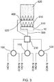
- a device with three mixing heads 100, 110 and 120 is shown here.
- Each of these three mixing heads receives a product stream with a polyol component R-OH and a product stream with an isocyanate component R-NCO.
- R-OH and R-NCO do of course not stand for monoalcohols and monoisocyanates, but generally for polyols and polyisocyanates and blowing agents and other additives that are still present in these feed streams.
- the mixing heads 100, 110, 120 combine their feed streams to form product streams which are fed to a distributor 230 connected to the mixing heads.
- the distributor 230 therefore has at least as many inputs as there are mixing heads.
- the product streams thus contain the foamable reaction mixture.
- the product stream is homogenized in the distributor 230 so that, for example, differences in the progress of the reaction over time or differences in the properties of the educt streams caused by time are compensated for.
- time-related differences in the properties of the educt streams it can be, for example, differences that are based on density fluctuations or fluctuations in the delivery rate of the educt streams to the mixing heads.
- the geometry of the distributor is preferably chosen so that the path of the homogenized reaction mixture to the discharge lines is of the same length. It is also advantageous if the cross-section of the distributor outlets is identical for all distributor outlets. The cross-sections of the distributor inlets, on the other hand, can also be different.
- the material of the distributor can be selected from steel, stainless steel, aluminum and plastics. In any case, the selected material must be able to withstand the pressures and temperatures in the mixing head.
- a distributor 230 can be constructed, for example, in such a way that two distributor heads, such as those shown in FIG EP 1 857 248 A2 ([0023], Fig. 1 ) are described under the designation "distributor head", can be connected in series.
- the flow through the first distributor head is reversed, i.e. the product flows coming from the mixing heads enter the first (reversed) distributor head via the several openings, are homogenized there and leave the distributor head as a product flow, which then enters another distributor head, where it is again distributed over several product streams. This is in FIG 2 shown in more detail.
- the reaction mixture leaves the distributor 230 via 7 discharge lines 300, which each end in discharge openings 400.
- the distributor has fifteen discharge lines 300.
- the discharge lines 300 can be designed to be flexible or rigid, flexible discharge lines being preferred.
- the discharge lines 300 are attached to a fastening rail 500, as a result of which the position of the discharge openings 400 is fixed.
- the reaction mixture leaves the individual discharge openings 400 and contacts a cover layer 10, represented by its dashed outline and moving away from the discharge openings, essentially over its entire width.
- a cover layer represented by its dashed outline and moving away from the discharge openings, essentially over its entire width.
- the individual strips of the reaction mixture combine to form the foam layer 600 on the cover layer.
- the number of mixing heads in these embodiments of the device according to the invention and the method according to the invention can be 2, 3 (as shown here), 4, 5, 6 or even greater.
- the number of discharge lines per distributor can be 7, 8, 9, 10, 11, 12, 13, 14, 15 (as shown here) or even greater.
- This embodiment has the additional advantage that one basically only has to work with one quality of the reaction mixture.
- Another advantage over existing outlet systems is that precise positioning of the outlet streams, both symmetrical and asymmetrical, can be achieved through the use of flexible hoses, which are preferably flexible. This can lead to advantages in the panel geometry or it allows targeted product application, for example in the beads of a roof element. This application method can be used for the production of metal panel sandwich composite elements, insulation panels and continuous blocks.
- Casting rakes that can be used here can be used, for example, as single casting rakes or pairs of casting rakes, as in EP 1 857 248 A2 , EP 2 614 944 A1 or EP 2 804 736 A1 described, be executed.
- the inlet to the casting rake (s) can be, for example, in the middle or on the side.
- each of these three mixing heads shows a device with three mixing heads 100, 110 and 120.
- Each of these three mixing heads receives a product stream with a polyol component R-OH and a product stream with an isocyanate component R-NCO.
- R-OH and R-NCO do of course not stand for monoalcohols and monoisocyanates, but generally for polyols and polyisocyanates and in these feed streams Propellants and other additives that are still present.
- the mixing heads 100, 110, 120 combine their feed streams to form product streams which are fed to a distributor 230 connected to the mixing heads.
- the product streams thus contain the foamable reaction mixture.
- the product stream is homogenized in the distributor 230 so that, for example, differences in the progress of the reaction over time or differences in the properties of the educt streams due to time are compensated for.
- time-related differences in the properties of the educt streams it can be, for example, differences that are based on density fluctuations or fluctuations in the delivery rate of the educt streams to the mixing heads.
- the reaction mixture leaves the distributor 230 via discharge lines 300, which each end in casting rakes 500, 510, 520, 530 with discharge openings 400, 410, 420, 430.
- the distributor has three discharge lines 300, in which FIG. 3rd
- the embodiment shown is one or more discharge lines 300, in FIG. 4th it is a discharge line which, in the exemplary case shown, represents a direct connection to a casting rake 400.
- FIG. 5 there are three discharge lines 300.
- FIG. 3rd there can be two discharge services, it can - as in FIG.
- the discharge lines 300 can be designed to be flexible or rigid, flexible discharge lines being preferred.
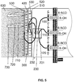
- FIG. 5 a possible distributor 230, which homogenizes and redistributes the product streams emerging from the mixing heads, is shown in more detail.
- two distributor heads 231, 232 as shown, for example, in FIG EP 1 857 248 A2 ([0023], Fig. 1 ) are described under the designation "distributor head", can be connected in series.
- the flow through the first distributor head 231 is reversed, i.e. the product flows coming from the mixing heads enter the first (reversed) distributor head via the several openings, are homogenized there and leave the distributor head as a product flow which then flows into a further distributor head 232 occurs, where it is again distributed over several product streams.
- a pipe branch such as a T-piece or a Y-piece, in particular a T-shaped branch of the discharge line, can also be used. Will be like in FIG. 4th If the product flow is shown only fed to one discharge line (in this case directly to the casting rake), the further distributor head 232 can be omitted entirely.
- the reaction mixture leaves the individual discharge openings 400 of the casting rakes 500, 510, 520, 530 and makes contact with a cover layer, not shown, moving away from the discharge openings. Due to the expansion of the foaming reaction mixture, the unite individual strips of the reaction mixture for foam layer 600 on the cover layer.
- the number of mixing heads in these embodiments of the device according to the invention and the method according to the invention can be 2, 3 (as shown here), 4, 5, 6 or even greater.
- the number of casting rakes can be 3, (as in FIG. 2 shown), 2 (as in FIG. 3rd shown), 4, 5, 6 or even larger.
- the number of openings per casting rake can be 4, 5 (as shown here), 6, 7, 8, 9, 10 or even greater.
- the device according to the invention contains 2, 3 or 4 mixing heads and only one casting rake or a pair of casting rakes (as in FIG. 4th shown).
- Casting rakes that can be used here can be used, for example, as single casting rakes or pairs of casting rakes, as in EP 1 857 248 A2 , EP 2 614 944 A1 or EP 2 804 736 A1 described, be executed.
- the inlet to the casting rake (s) can be, for example, in the middle or on the side. This application method can be used for the production of metal panel sandwich composite elements, insulation panels and continuous blocks.
- This embodiment has the additional advantage that one basically only has to work with one quality of the reaction mixture.
- Another advantage over existing outlet systems is that precise positioning of the outlet streams, both symmetrical and asymmetrical, can be achieved through the use of flexible hoses, which are preferably flexible. This can lead to advantages in the panel geometry or it allows targeted product application, for example in an asymmetrical roof panel.
- At least two casting rakes 520 can be used in the device and in the method and for at least two of the casting rakes 520 to be arranged next to one another as seen transversely to the direction of movement of the cover layer and to be arranged one behind the other as seen in the direction of movement of the cover layer.
- This arrangement is in FIG. 2 shown.
- the three casting rakes 520 are in FIG. 2 arranged essentially next to each other.
- the fact that the middle casting rake is offset somewhat to the rear is intended to make it clear that such casting rakes have certain space requirements that may preclude positioning them directly next to one another.
- At least two casting rakes 510, 520 can be used in the device and in the method and at least two of the casting rakes 510, 520, viewed in the direction of movement of the cover layer, to be arranged directly one behind the other or slightly offset one behind the other, so that a casting rake from the discharge openings 400 510 discharged reaction mixture at least partially contacted from the discharge openings 400 of the other casting rake 520 reaction mixture discharged.
- This arrangement is in FIG. 3rd shown.
- the reaction mixture emerging from the casting rake 510 can flow between the flows from the other casting rake 520, so that an even better flow of the flows is achieved.
- the reaction mixture leaves the individual discharge openings 400, 410, 420 of the casting rakes 500, 510, 520, 530 and contacts a cover layer 10, represented by its dashed outline and moving away from the discharge openings, essentially over its entire width.
- a cover layer 10 represented by its dashed outline and moving away from the discharge openings, essentially over its entire width.
- the individual strips of the reaction mixture combine to form the foam layer 610, 620, 630 on the cover layer 10.
- the slight offset of the casting rakes that may be present is in their The order of magnitude depends on the number of casting rakes and the distance between the outlet openings.
- the offset of the casting rakes with respect to one another is at most a length which corresponds to 50% of the distance between two adjacent outlet openings of the casting rakes.
- a preferred arrangement is that the three casting rakes are offset from one another by a length which corresponds to approximately 1/3 of the distance between two adjacent outlet openings 400 of the casting rakes. This arrangement is in FIG. 5 shown.
- the individual strips of the reaction mixture 710, 720, 730 then combine again to form a foam layer 630.
- the order can be carried out in and against the direction of the belt. Even in one embodiment, as shown in one of the figures, it can be advantageous that not all casting rakes are placed at the same angle to the cover layer.
Landscapes
- Polyurethanes Or Polyureas (AREA)
- Casting Or Compression Moulding Of Plastics Or The Like (AREA)
Claims (5)
- Procédé d'application d'un mélange réactionnel moussant sur une couche de revêtement mobile (10), le mélange réactionnel qui provient des ouvertures de sortie (400) étant appliqué sur la couche de revêtement et la couche de revêtement se déplaçant à une vitesse ≥ 15 mètres par minute par rapport aux ouvertures de sortie (400),
le mélange réactionnel qui provient de ≥ 7 ouvertures de sortie (400) étant appliqué simultanément sur la couche de revêtement (10),
le procédé comprenant en outre les étapes suivantes :- fournir une pluralité de têtes de mélange (100, 110, 120), chaque tête de mélange étant conçue pour mélanger deux flux d'éduit ou plus pour former un flux de produit ;- fournir un distributeur (230), le distributeur comportant une ou plusieurs conduites de sortie (300), le distributeur étant relié aux flux de produit des têtes de mélange (100, 110, 120) et le distributeur étant conçu pour réunir les flux de produit des têtes de mélange (100, 110, 120) et pour les distribuer de manière homogène en termes de composition de substances sur l'une ou plusieurs conduites de sortie (300) ;- fournir un ou plusieurs râteaux de coulée (510, 520), le nombre de râteaux de coulée correspondant au nombre de conduites de sortie (300) du distributeur (230), chaque râteau de coulée étant relié à une conduite de sortie et chaque râteau de coulée comportant ≥ 4 ouvertures de sortie (400) ;- mélanger deux flux d'éduit ou plus dans chacune des têtes de mélange (100, 110, 120) pour obtenir un flux de produit sortant de chacune des têtes de mélange, le flux de produit comprenant un mélange réactionnel moussant ;- réunir les flux de produits dans le distributeur (230) ;- distribuer les flux de produits réunis sur l'une ou plusieurs conduites de sortie (300) du distributeur (230) ;- appliquer le mélange réactionnel depuis les ouvertures de sortie (400) d'un ou plusieurs râteaux de coulée (510, 520) sur la couche de revêtement (10). - Procédé selon la revendication 1, au moins deux râteaux de coulée (510, 520) étant utilisés et au moins deux des râteaux de coulée (510, 520) étant disposés l'un à côté de l'autre lorsque l'on observe transversalement au sens de déplacement de la couche de revêtement (10) et l'une derrière l'autre lorsque l'on observe dans le sens de déplacement de la couche de revêtement (10).
- Procédé selon la revendication 2, les au moins deux râteaux de coulée (510, 520) étant disposés en étant décalés l'un de l'autre d'une longueur qui est au maximum de 50 % de la distance entre deux ouvertures de sortie adjacentes (400) des râteaux de coulée (510, 520) .
- Procédé selon l'une des revendications précédentes, le mélange réactionnel comprenant un polyol, un polyisocyanate et un agent moussant.
- Dispositif d'application d'un mélange réactionnel moussant sur une couche de revêtement mobile, le mélange réactionnel étant appliqué sur la couche de revêtement (10) à partir des ouvertures de sortie (400) ,
le dispositif comprend ≥ 7 ouvertures de sortie (400) et comprenant en outre :- une pluralité de têtes de mélange (100, 110, 120), chaque tête de mélange étant conçue pour mélanger deux flux d'éduit ou plus afin de former un flux de produit ;- un distributeur (230), le distributeur comportant une ou plusieurs conduites de sortie (300), le distributeur étant relié aux flux de produit des têtes de mélange (100, 110, 120) et le distributeur étant conçu pour réunir les flux de produit des têtes de mélange (100, 110, 120) et pour les distribuer de manière homogène en termes de composition de substances sur l'une ou plusieurs conduites de sortie (300) ;- un ou plusieurs râteaux de coulée (510, 520), le nombre de râteaux de coulée correspondant au nombre de conduites de sortie (300) du distributeur (230), chaque râteau de coulée étant relié à une conduite de sortie et chaque râteau de coulée comportant ≥ 4 ouvertures de sortie (400).
Priority Applications (1)
| Application Number | Priority Date | Filing Date | Title |
|---|---|---|---|
| PL18701201T PL3576922T3 (pl) | 2017-01-31 | 2018-01-30 | Sposób i urządzenie do wytwarzania piankowych elementów kompozytowych |
Applications Claiming Priority (2)
| Application Number | Priority Date | Filing Date | Title |
|---|---|---|---|
| EP17154071 | 2017-01-31 | ||
| PCT/EP2018/052247 WO2018141735A1 (fr) | 2017-01-31 | 2018-01-30 | Procédé et dispositif de fabrication d'éléments composites expansés |
Publications (2)
| Publication Number | Publication Date |
|---|---|
| EP3576922A1 EP3576922A1 (fr) | 2019-12-11 |
| EP3576922B1 true EP3576922B1 (fr) | 2021-06-09 |
Family
ID=58158762
Family Applications (1)
| Application Number | Title | Priority Date | Filing Date |
|---|---|---|---|
| EP18701201.8A Active EP3576922B1 (fr) | 2017-01-31 | 2018-01-30 | Procédé et système de fabrication d'éléments composites en mousse |
Country Status (5)
| Country | Link |
|---|---|
| US (1) | US20190344484A1 (fr) |
| EP (1) | EP3576922B1 (fr) |
| CN (1) | CN110248791A (fr) |
| PL (1) | PL3576922T3 (fr) |
| WO (1) | WO2018141735A1 (fr) |
Families Citing this family (1)
| Publication number | Priority date | Publication date | Assignee | Title |
|---|---|---|---|---|
| EP3804939A1 (fr) | 2019-10-11 | 2021-04-14 | Covestro Deutschland AG | Procédé et dispositif de fabrication d'éléments composites en mousse |
Family Cites Families (13)
| Publication number | Priority date | Publication date | Assignee | Title |
|---|---|---|---|---|
| US4572435A (en) * | 1984-05-30 | 1986-02-25 | Owens-Corning Fiberglas Corporation | Foamable liquid distributing means |
| US4945854A (en) * | 1989-03-17 | 1990-08-07 | Mobay Corporation | Apparatus for the distribution of a foamable reaction mixture upon a moving base |
| DE4202736A1 (de) * | 1992-01-31 | 1993-08-05 | Elastogran Gmbh | Auftragsvorrichtung fuer mehrkomponenten-kunststoff, insbesondere polyurethan |
| US5846462A (en) * | 1997-05-16 | 1998-12-08 | Thompson; Edward J. | Method and apparatus for making high compression structural foam |
| DE102006022760A1 (de) * | 2006-05-16 | 2007-11-22 | Bayer Materialscience Ag | Strang-Technik, Vorrichtung und Verfahren |
| EP2216156A1 (fr) | 2009-02-05 | 2010-08-11 | Bayer MaterialScience AG | Dispositif haute pression |
| EP2233271A1 (fr) | 2009-03-25 | 2010-09-29 | Bayer MaterialScience AG | Eléments composites en sandwich |
| DE202009015838U1 (de) * | 2009-11-20 | 2010-02-18 | Basf Se | Vorrichtung zum Auftrag von flüssigen Reaktionsgemischen auf eine Deckschicht |
| EP2614944A1 (fr) | 2012-01-16 | 2013-07-17 | Bayer Intellectual Property GmbH | Dispositif d'application d'un mélange réactif moussant |
| EP2804736B8 (fr) | 2012-01-16 | 2020-11-04 | Covestro Intellectual Property GmbH & Co. KG | Dispositif permettant d'appliquer un mélange réactif moussant |
| EP2614943A1 (fr) * | 2012-01-16 | 2013-07-17 | Bayer Intellectual Property GmbH | Dispositif d'application d'un mélange réactif moussant |
| CA2901973C (fr) * | 2013-02-26 | 2019-03-12 | Asahi Kasei Construction Materials Corporation | Panneau de mousse de resine phenolique, et son procede de fabrication |
| MX380822B (es) * | 2014-09-11 | 2025-03-12 | Huntsman Int Llc | Método para diseñar y fabricar una barra distribuidora para aplicar una mezcla viscosa líquida espumable en un laminador. |
-
2018
- 2018-01-30 US US16/468,538 patent/US20190344484A1/en not_active Abandoned
- 2018-01-30 PL PL18701201T patent/PL3576922T3/pl unknown
- 2018-01-30 WO PCT/EP2018/052247 patent/WO2018141735A1/fr not_active Ceased
- 2018-01-30 CN CN201880009485.7A patent/CN110248791A/zh active Pending
- 2018-01-30 EP EP18701201.8A patent/EP3576922B1/fr active Active
Also Published As
| Publication number | Publication date |
|---|---|
| US20190344484A1 (en) | 2019-11-14 |
| EP3576922A1 (fr) | 2019-12-11 |
| CN110248791A (zh) | 2019-09-17 |
| PL3576922T3 (pl) | 2021-12-13 |
| WO2018141735A1 (fr) | 2018-08-09 |
Similar Documents
| Publication | Publication Date | Title |
|---|---|---|
| EP3576921A1 (fr) | Procédé et système de fabrication d'éléments composites expansés | |
| EP2234732B1 (fr) | Procédé et dispositif de fabrication d'éléments composites à partir de mousses à base d'isocyanate | |
| EP2125323B1 (fr) | Procédé de fabrication d'éléments composites sur la base de mousses à base d'isocyanate | |
| EP2804735B1 (fr) | Procédé d'application d'un mélange réactif moussant | |
| EP2804736A1 (fr) | Dispositif permettant d'appliquer un mélange réactif moussant | |
| EP3577150A1 (fr) | Procédé pour produire des mousses rigides à base de polyuréthane (pur) et de polyuréthane/polyisocyanurate (pur/pir) | |
| WO2010108615A1 (fr) | Éléments composites en sandwich | |
| EP3576922B1 (fr) | Procédé et système de fabrication d'éléments composites en mousse | |
| EP3576923B1 (fr) | Procédé et système de fabrication d'éléments composites en mousse | |
| EP3804939A1 (fr) | Procédé et dispositif de fabrication d'éléments composites en mousse | |
| EP2614943A1 (fr) | Dispositif d'application d'un mélange réactif moussant | |
| WO2013014055A1 (fr) | Mousse dure de pur-pir à adhérence améliorée dans des éléments composites | |
| EP1595904A2 (fr) | Tuyau insulé contenant une polyuréthane préparé à partir d'acide formique | |
| WO2013023965A1 (fr) | Dispositif servant à l'application de mélanges réactionnels moussants | |
| EP3710216A1 (fr) | Dispositif variable et procédé destiné à appliquer un mélange réactionnel expansible sur une couche de recouvrement en mouvement | |
| EP3648974B1 (fr) | Procédé de fabrication d'éléments composites avec application ciblée d'un adhésif | |
| EP4275857A1 (fr) | Outil destiné à la production de matières expansées |
Legal Events
| Date | Code | Title | Description |
|---|---|---|---|
| STAA | Information on the status of an ep patent application or granted ep patent |
Free format text: STATUS: UNKNOWN |
|
| STAA | Information on the status of an ep patent application or granted ep patent |
Free format text: STATUS: THE INTERNATIONAL PUBLICATION HAS BEEN MADE |
|
| PUAI | Public reference made under article 153(3) epc to a published international application that has entered the european phase |
Free format text: ORIGINAL CODE: 0009012 |
|
| STAA | Information on the status of an ep patent application or granted ep patent |
Free format text: STATUS: REQUEST FOR EXAMINATION WAS MADE |
|
| 17P | Request for examination filed |
Effective date: 20190902 |
|
| AK | Designated contracting states |
Kind code of ref document: A1 Designated state(s): AL AT BE BG CH CY CZ DE DK EE ES FI FR GB GR HR HU IE IS IT LI LT LU LV MC MK MT NL NO PL PT RO RS SE SI SK SM TR |
|
| AX | Request for extension of the european patent |
Extension state: BA ME |
|
| DAV | Request for validation of the european patent (deleted) | ||
| DAX | Request for extension of the european patent (deleted) | ||
| RAP1 | Party data changed (applicant data changed or rights of an application transferred) |
Owner name: COVESTRO DEUTSCHLAND AG |
|
| RAP1 | Party data changed (applicant data changed or rights of an application transferred) |
Owner name: COVESTRO INTELLECTUAL PROPERTY GMBH & CO. KG |
|
| GRAP | Despatch of communication of intention to grant a patent |
Free format text: ORIGINAL CODE: EPIDOSNIGR1 |
|
| STAA | Information on the status of an ep patent application or granted ep patent |
Free format text: STATUS: GRANT OF PATENT IS INTENDED |
|
| INTG | Intention to grant announced |
Effective date: 20210218 |
|
| GRAS | Grant fee paid |
Free format text: ORIGINAL CODE: EPIDOSNIGR3 |
|
| GRAA | (expected) grant |
Free format text: ORIGINAL CODE: 0009210 |
|
| STAA | Information on the status of an ep patent application or granted ep patent |
Free format text: STATUS: THE PATENT HAS BEEN GRANTED |
|
| AK | Designated contracting states |
Kind code of ref document: B1 Designated state(s): AL AT BE BG CH CY CZ DE DK EE ES FI FR GB GR HR HU IE IS IT LI LT LU LV MC MK MT NL NO PL PT RO RS SE SI SK SM TR |
|
| REG | Reference to a national code |
Ref country code: GB Ref legal event code: FG4D Free format text: NOT ENGLISH |
|
| REG | Reference to a national code |
Ref country code: CH Ref legal event code: EP Ref country code: AT Ref legal event code: REF Ref document number: 1400087 Country of ref document: AT Kind code of ref document: T Effective date: 20210615 |
|
| REG | Reference to a national code |
Ref country code: DE Ref legal event code: R096 Ref document number: 502018005611 Country of ref document: DE |
|
| REG | Reference to a national code |
Ref country code: IE Ref legal event code: FG4D Free format text: LANGUAGE OF EP DOCUMENT: GERMAN |
|
| REG | Reference to a national code |
Ref country code: NL Ref legal event code: FP |
|
| REG | Reference to a national code |
Ref country code: LT Ref legal event code: MG9D |
|
| PG25 | Lapsed in a contracting state [announced via postgrant information from national office to epo] |
Ref country code: FI Free format text: LAPSE BECAUSE OF FAILURE TO SUBMIT A TRANSLATION OF THE DESCRIPTION OR TO PAY THE FEE WITHIN THE PRESCRIBED TIME-LIMIT Effective date: 20210609 Ref country code: HR Free format text: LAPSE BECAUSE OF FAILURE TO SUBMIT A TRANSLATION OF THE DESCRIPTION OR TO PAY THE FEE WITHIN THE PRESCRIBED TIME-LIMIT Effective date: 20210609 Ref country code: LT Free format text: LAPSE BECAUSE OF FAILURE TO SUBMIT A TRANSLATION OF THE DESCRIPTION OR TO PAY THE FEE WITHIN THE PRESCRIBED TIME-LIMIT Effective date: 20210609 Ref country code: BG Free format text: LAPSE BECAUSE OF FAILURE TO SUBMIT A TRANSLATION OF THE DESCRIPTION OR TO PAY THE FEE WITHIN THE PRESCRIBED TIME-LIMIT Effective date: 20210909 |
|
| PG25 | Lapsed in a contracting state [announced via postgrant information from national office to epo] |
Ref country code: NO Free format text: LAPSE BECAUSE OF FAILURE TO SUBMIT A TRANSLATION OF THE DESCRIPTION OR TO PAY THE FEE WITHIN THE PRESCRIBED TIME-LIMIT Effective date: 20210909 Ref country code: LV Free format text: LAPSE BECAUSE OF FAILURE TO SUBMIT A TRANSLATION OF THE DESCRIPTION OR TO PAY THE FEE WITHIN THE PRESCRIBED TIME-LIMIT Effective date: 20210609 Ref country code: RS Free format text: LAPSE BECAUSE OF FAILURE TO SUBMIT A TRANSLATION OF THE DESCRIPTION OR TO PAY THE FEE WITHIN THE PRESCRIBED TIME-LIMIT Effective date: 20210609 Ref country code: SE Free format text: LAPSE BECAUSE OF FAILURE TO SUBMIT A TRANSLATION OF THE DESCRIPTION OR TO PAY THE FEE WITHIN THE PRESCRIBED TIME-LIMIT Effective date: 20210609 Ref country code: GR Free format text: LAPSE BECAUSE OF FAILURE TO SUBMIT A TRANSLATION OF THE DESCRIPTION OR TO PAY THE FEE WITHIN THE PRESCRIBED TIME-LIMIT Effective date: 20210910 |
|
| PG25 | Lapsed in a contracting state [announced via postgrant information from national office to epo] |
Ref country code: RO Free format text: LAPSE BECAUSE OF FAILURE TO SUBMIT A TRANSLATION OF THE DESCRIPTION OR TO PAY THE FEE WITHIN THE PRESCRIBED TIME-LIMIT Effective date: 20210609 Ref country code: PT Free format text: LAPSE BECAUSE OF FAILURE TO SUBMIT A TRANSLATION OF THE DESCRIPTION OR TO PAY THE FEE WITHIN THE PRESCRIBED TIME-LIMIT Effective date: 20211011 Ref country code: CZ Free format text: LAPSE BECAUSE OF FAILURE TO SUBMIT A TRANSLATION OF THE DESCRIPTION OR TO PAY THE FEE WITHIN THE PRESCRIBED TIME-LIMIT Effective date: 20210609 Ref country code: SM Free format text: LAPSE BECAUSE OF FAILURE TO SUBMIT A TRANSLATION OF THE DESCRIPTION OR TO PAY THE FEE WITHIN THE PRESCRIBED TIME-LIMIT Effective date: 20210609 Ref country code: SK Free format text: LAPSE BECAUSE OF FAILURE TO SUBMIT A TRANSLATION OF THE DESCRIPTION OR TO PAY THE FEE WITHIN THE PRESCRIBED TIME-LIMIT Effective date: 20210609 Ref country code: EE Free format text: LAPSE BECAUSE OF FAILURE TO SUBMIT A TRANSLATION OF THE DESCRIPTION OR TO PAY THE FEE WITHIN THE PRESCRIBED TIME-LIMIT Effective date: 20210609 Ref country code: ES Free format text: LAPSE BECAUSE OF FAILURE TO SUBMIT A TRANSLATION OF THE DESCRIPTION OR TO PAY THE FEE WITHIN THE PRESCRIBED TIME-LIMIT Effective date: 20210609 |
|
| REG | Reference to a national code |
Ref country code: DE Ref legal event code: R097 Ref document number: 502018005611 Country of ref document: DE |
|
| PLBE | No opposition filed within time limit |
Free format text: ORIGINAL CODE: 0009261 |
|
| STAA | Information on the status of an ep patent application or granted ep patent |
Free format text: STATUS: NO OPPOSITION FILED WITHIN TIME LIMIT |
|
| PG25 | Lapsed in a contracting state [announced via postgrant information from national office to epo] |
Ref country code: DK Free format text: LAPSE BECAUSE OF FAILURE TO SUBMIT A TRANSLATION OF THE DESCRIPTION OR TO PAY THE FEE WITHIN THE PRESCRIBED TIME-LIMIT Effective date: 20210609 |
|
| 26N | No opposition filed |
Effective date: 20220310 |
|
| PG25 | Lapsed in a contracting state [announced via postgrant information from national office to epo] |
Ref country code: AL Free format text: LAPSE BECAUSE OF FAILURE TO SUBMIT A TRANSLATION OF THE DESCRIPTION OR TO PAY THE FEE WITHIN THE PRESCRIBED TIME-LIMIT Effective date: 20210609 |
|
| PG25 | Lapsed in a contracting state [announced via postgrant information from national office to epo] |
Ref country code: MC Free format text: LAPSE BECAUSE OF FAILURE TO SUBMIT A TRANSLATION OF THE DESCRIPTION OR TO PAY THE FEE WITHIN THE PRESCRIBED TIME-LIMIT Effective date: 20210609 |
|
| REG | Reference to a national code |
Ref country code: CH Ref legal event code: PL |
|
| PG25 | Lapsed in a contracting state [announced via postgrant information from national office to epo] |
Ref country code: LU Free format text: LAPSE BECAUSE OF NON-PAYMENT OF DUE FEES Effective date: 20220130 |
|
| PG25 | Lapsed in a contracting state [announced via postgrant information from national office to epo] |
Ref country code: LI Free format text: LAPSE BECAUSE OF NON-PAYMENT OF DUE FEES Effective date: 20220131 Ref country code: CH Free format text: LAPSE BECAUSE OF NON-PAYMENT OF DUE FEES Effective date: 20220131 |
|
| PG25 | Lapsed in a contracting state [announced via postgrant information from national office to epo] |
Ref country code: IE Free format text: LAPSE BECAUSE OF NON-PAYMENT OF DUE FEES Effective date: 20220130 |
|
| REG | Reference to a national code |
Ref country code: AT Ref legal event code: MM01 Ref document number: 1400087 Country of ref document: AT Kind code of ref document: T Effective date: 20230130 |
|
| PG25 | Lapsed in a contracting state [announced via postgrant information from national office to epo] |
Ref country code: AT Free format text: LAPSE BECAUSE OF NON-PAYMENT OF DUE FEES Effective date: 20230130 |
|
| PG25 | Lapsed in a contracting state [announced via postgrant information from national office to epo] |
Ref country code: MK Free format text: LAPSE BECAUSE OF FAILURE TO SUBMIT A TRANSLATION OF THE DESCRIPTION OR TO PAY THE FEE WITHIN THE PRESCRIBED TIME-LIMIT Effective date: 20210609 Ref country code: CY Free format text: LAPSE BECAUSE OF FAILURE TO SUBMIT A TRANSLATION OF THE DESCRIPTION OR TO PAY THE FEE WITHIN THE PRESCRIBED TIME-LIMIT Effective date: 20210609 Ref country code: AT Free format text: LAPSE BECAUSE OF NON-PAYMENT OF DUE FEES Effective date: 20230130 |
|
| PG25 | Lapsed in a contracting state [announced via postgrant information from national office to epo] |
Ref country code: HU Free format text: LAPSE BECAUSE OF FAILURE TO SUBMIT A TRANSLATION OF THE DESCRIPTION OR TO PAY THE FEE WITHIN THE PRESCRIBED TIME-LIMIT; INVALID AB INITIO Effective date: 20180130 |
|
| PG25 | Lapsed in a contracting state [announced via postgrant information from national office to epo] |
Ref country code: MT Free format text: LAPSE BECAUSE OF FAILURE TO SUBMIT A TRANSLATION OF THE DESCRIPTION OR TO PAY THE FEE WITHIN THE PRESCRIBED TIME-LIMIT Effective date: 20210609 |
|
| PGFP | Annual fee paid to national office [announced via postgrant information from national office to epo] |
Ref country code: PL Payment date: 20241231 Year of fee payment: 8 |
|
| PG25 | Lapsed in a contracting state [announced via postgrant information from national office to epo] |
Ref country code: TR Free format text: LAPSE BECAUSE OF FAILURE TO SUBMIT A TRANSLATION OF THE DESCRIPTION OR TO PAY THE FEE WITHIN THE PRESCRIBED TIME-LIMIT Effective date: 20210609 |
|
| PGFP | Annual fee paid to national office [announced via postgrant information from national office to epo] |
Ref country code: GB Payment date: 20251218 Year of fee payment: 9 |
|
| PGFP | Annual fee paid to national office [announced via postgrant information from national office to epo] |
Ref country code: NL Payment date: 20251225 Year of fee payment: 9 Ref country code: FR Payment date: 20251222 Year of fee payment: 9 |
|
| PGFP | Annual fee paid to national office [announced via postgrant information from national office to epo] |
Ref country code: DE Payment date: 20251216 Year of fee payment: 9 |
|
| PGFP | Annual fee paid to national office [announced via postgrant information from national office to epo] |
Ref country code: AT Payment date: 20260410 Year of fee payment: 5 |
|
| PGFP | Annual fee paid to national office [announced via postgrant information from national office to epo] |
Ref country code: BE Payment date: 20260106 Year of fee payment: 9 Ref country code: IT Payment date: 20251230 Year of fee payment: 9 |