EP3577345B1 - Pompe de cale ayant une surface de détection extérieure dotée de nervures - Google Patents
Pompe de cale ayant une surface de détection extérieure dotée de nervures Download PDFInfo
- Publication number
- EP3577345B1 EP3577345B1 EP18748146.0A EP18748146A EP3577345B1 EP 3577345 B1 EP3577345 B1 EP 3577345B1 EP 18748146 A EP18748146 A EP 18748146A EP 3577345 B1 EP3577345 B1 EP 3577345B1
- Authority
- EP
- European Patent Office
- Prior art keywords
- pump
- ribs
- liquid
- outside
- sensing device
- Prior art date
- Legal status (The legal status is an assumption and is not a legal conclusion. Google has not performed a legal analysis and makes no representation as to the accuracy of the status listed.)
- Active
Links
Images




Classifications
-
- F—MECHANICAL ENGINEERING; LIGHTING; HEATING; WEAPONS; BLASTING
- F04—POSITIVE - DISPLACEMENT MACHINES FOR LIQUIDS; PUMPS FOR LIQUIDS OR ELASTIC FLUIDS
- F04D—NON-POSITIVE-DISPLACEMENT PUMPS
- F04D29/00—Details, component parts, or accessories
- F04D29/40—Casings; Connections of working fluid
- F04D29/42—Casings; Connections of working fluid for radial or helico-centrifugal pumps
- F04D29/426—Casings; Connections of working fluid for radial or helico-centrifugal pumps especially adapted for liquid pumps
-
- F—MECHANICAL ENGINEERING; LIGHTING; HEATING; WEAPONS; BLASTING
- F04—POSITIVE - DISPLACEMENT MACHINES FOR LIQUIDS; PUMPS FOR LIQUIDS OR ELASTIC FLUIDS
- F04D—NON-POSITIVE-DISPLACEMENT PUMPS
- F04D15/00—Control, e.g. regulation, of pumps, pumping installations or systems
- F04D15/02—Stopping of pumps, or operating valves, on occurrence of unwanted conditions
-
- B—PERFORMING OPERATIONS; TRANSPORTING
- B63—SHIPS OR OTHER WATERBORNE VESSELS; RELATED EQUIPMENT
- B63B—SHIPS OR OTHER WATERBORNE VESSELS; EQUIPMENT FOR SHIPPING
- B63B29/00—Accommodation for crew or passengers not otherwise provided for
- B63B29/02—Cabins or other living spaces; Construction or arrangement thereof
- B63B29/14—Closet or like flushing arrangements; Washing or bathing facilities peculiar to ships
-
- E—FIXED CONSTRUCTIONS
- E03—WATER SUPPLY; SEWERAGE
- E03F—SEWERS; CESSPOOLS
- E03F5/00—Sewerage structures
- E03F5/22—Adaptations of pumping plants for lifting sewage
-
- F—MECHANICAL ENGINEERING; LIGHTING; HEATING; WEAPONS; BLASTING
- F04—POSITIVE - DISPLACEMENT MACHINES FOR LIQUIDS; PUMPS FOR LIQUIDS OR ELASTIC FLUIDS
- F04D—NON-POSITIVE-DISPLACEMENT PUMPS
- F04D13/00—Pumping installations or systems
-
- F—MECHANICAL ENGINEERING; LIGHTING; HEATING; WEAPONS; BLASTING
- F04—POSITIVE - DISPLACEMENT MACHINES FOR LIQUIDS; PUMPS FOR LIQUIDS OR ELASTIC FLUIDS
- F04D—NON-POSITIVE-DISPLACEMENT PUMPS
- F04D13/00—Pumping installations or systems
- F04D13/02—Units comprising pumps and their driving means
- F04D13/06—Units comprising pumps and their driving means the pump being electrically driven
- F04D13/08—Units comprising pumps and their driving means the pump being electrically driven for submerged use
-
- F—MECHANICAL ENGINEERING; LIGHTING; HEATING; WEAPONS; BLASTING
- F04—POSITIVE - DISPLACEMENT MACHINES FOR LIQUIDS; PUMPS FOR LIQUIDS OR ELASTIC FLUIDS
- F04D—NON-POSITIVE-DISPLACEMENT PUMPS
- F04D13/00—Pumping installations or systems
- F04D13/16—Pumping installations or systems with storage reservoirs
-
- F—MECHANICAL ENGINEERING; LIGHTING; HEATING; WEAPONS; BLASTING
- F04—POSITIVE - DISPLACEMENT MACHINES FOR LIQUIDS; PUMPS FOR LIQUIDS OR ELASTIC FLUIDS
- F04D—NON-POSITIVE-DISPLACEMENT PUMPS
- F04D15/00—Control, e.g. regulation, of pumps, pumping installations or systems
- F04D15/0088—Testing machines
-
- F—MECHANICAL ENGINEERING; LIGHTING; HEATING; WEAPONS; BLASTING
- F04—POSITIVE - DISPLACEMENT MACHINES FOR LIQUIDS; PUMPS FOR LIQUIDS OR ELASTIC FLUIDS
- F04D—NON-POSITIVE-DISPLACEMENT PUMPS
- F04D15/00—Control, e.g. regulation, of pumps, pumping installations or systems
- F04D15/02—Stopping of pumps, or operating valves, on occurrence of unwanted conditions
- F04D15/0209—Stopping of pumps, or operating valves, on occurrence of unwanted conditions responsive to a condition of the working fluid
- F04D15/0218—Stopping of pumps, or operating valves, on occurrence of unwanted conditions responsive to a condition of the working fluid the condition being a liquid level or a lack of liquid supply
-
- F—MECHANICAL ENGINEERING; LIGHTING; HEATING; WEAPONS; BLASTING
- F04—POSITIVE - DISPLACEMENT MACHINES FOR LIQUIDS; PUMPS FOR LIQUIDS OR ELASTIC FLUIDS
- F04D—NON-POSITIVE-DISPLACEMENT PUMPS
- F04D15/00—Control, e.g. regulation, of pumps, pumping installations or systems
- F04D15/02—Stopping of pumps, or operating valves, on occurrence of unwanted conditions
- F04D15/0281—Stopping of pumps, or operating valves, on occurrence of unwanted conditions responsive to a condition not otherwise provided for
-
- G—PHYSICS
- G01—MEASURING; TESTING
- G01F—MEASURING VOLUME, VOLUME FLOW, MASS FLOW OR LIQUID LEVEL; METERING BY VOLUME
- G01F23/00—Indicating or measuring liquid level or level of fluent solid material, e.g. indicating in terms of volume or indicating by means of an alarm
- G01F23/22—Indicating or measuring liquid level or level of fluent solid material, e.g. indicating in terms of volume or indicating by means of an alarm by measuring physical variables, other than linear dimensions, pressure or weight, dependent on the level to be measured, e.g. by difference of heat transfer of steam or water
- G01F23/26—Indicating or measuring liquid level or level of fluent solid material, e.g. indicating in terms of volume or indicating by means of an alarm by measuring physical variables, other than linear dimensions, pressure or weight, dependent on the level to be measured, e.g. by difference of heat transfer of steam or water by measuring variations of capacity or inductance of capacitors or inductors arising from the presence of liquid or fluent solid material in the electric or electromagnetic fields
- G01F23/263—Indicating or measuring liquid level or level of fluent solid material, e.g. indicating in terms of volume or indicating by means of an alarm by measuring physical variables, other than linear dimensions, pressure or weight, dependent on the level to be measured, e.g. by difference of heat transfer of steam or water by measuring variations of capacity or inductance of capacitors or inductors arising from the presence of liquid or fluent solid material in the electric or electromagnetic fields by measuring variations in capacitance of capacitors
-
- F—MECHANICAL ENGINEERING; LIGHTING; HEATING; WEAPONS; BLASTING
- F05—INDEXING SCHEMES RELATING TO ENGINES OR PUMPS IN VARIOUS SUBCLASSES OF CLASSES F01-F04
- F05D—INDEXING SCHEME FOR ASPECTS RELATING TO NON-POSITIVE-DISPLACEMENT MACHINES OR ENGINES, GAS-TURBINES OR JET-PROPULSION PLANTS
- F05D2250/00—Geometry
- F05D2250/10—Two-dimensional
- F05D2250/18—Two-dimensional patterned
- F05D2250/181—Two-dimensional patterned ridged
Definitions
- the present invention relates to a pump; and more particularly to a bilge pump.
- a typical centrifugal pump fluid is accelerated through centrifugal forces exerted on it by an impeller, which are used to transmit energy to the fluid being pumped.
- the pump may be controlled by a system automated using a capacitive sensing device.
- On the bottom of the pump an impeller is located and protected against debris in the fluid by a strainer that will help to prevent some large particulates from getting stuck on the impeller and impede the rotation of the motor.
- the capacitive sensing device is integrated on a printed circuit board (PCB) that is programmed to control the function of the pumping unit.
- the sensor basically senses the presence of water and turns the pumping unit on to evacuate the water, e.g., on bilge and shower drain systems, once that water is down to a certain remnant level the PCB will automatic turn the pump off.
- Pumps used in this application are usually centrifugal type driven by a permanent magnet DC motor. These pumps feature an inlet and a discharge from which a hose connection is attached for routing of the discharge water out of the boat or vessel. Most of these pumps are controlled either manually by means of a panel mounted toggle switch or an automatic level switch. This level switch activates the pump motor when it senses the presence of water around the pump. Level switches usually are of the float type with dry contacts or an electronic sensor type. The switch can be a separate device or can be integral to the pump itself.
- the environments in which the pumps operate usually contain debris in varying amounts.
- the debris/contaminants may consist of oils, paper or cloth remnants from cleaning towels or other organic matter. These contaminants work to inhibit proper operation of the sensing device. Debris can sometimes adhere to the sensing surface, thereby causing false sensing signals where secondary failure modes can occur.
- US 2011/0146399 A1 describes a sensor system for sensing liquid level in a bilge.
- US 2006/0260993 A1 describes a sewage tank comprising ribs with for use with a pump.
- US 7 025 643 B1 describes a quick flush valve for flushing or winterizing of cooling systems of inboard marine engines.
- US 2006/0005622 A1 describes a sensor system for sensing liquid level in a bilge, for use in automatic bilge pump actuation.
- EP 3 091 234 A1 describes a submersible water pump, which includes a pump main body and a water level switch, the water level switch essentially consisting of at least two sensor units which are sufficiently exposed to water, as well as a control circuit unit which controls the activation and deactivation of the main pump body.
- a pump designed to inhibit the adhesion of debris on the sensing surface.
- This object is achieved by a pump comprising the features of claim 1.
- the geometry may include a series of ribs placed to decrease adhesion surface area. The theory is that if debris will not stick, this will allow the sensor to function as designed.
- the pumping unit improves the sensing effectiveness by changing the geometric design when compared to the known pumping units. Adding ribs at the sensing area will restrict towels and other objects from being in touch with the sensor area and prevent the pump from falsely sensing when no water is around to be pumped. In addition, these ribs in conjunction with a flat outside sensing surface improve the structural design for a better heat resistance, preventing the deformation when the unit is under thermal stress environment.
- the present invention is as defined in claim 1.
- the pump may also include one or more of the following features:
- the ribs may be arranged on the flat surface and dimensioned so that there is a space in-between adjacent ribs to receive the liquid between adjacent ribs when the object is stuck on, or in contact with, the ribs.
- the ribs may be arranged on the outside sensing surface vertically or horizontally in relation to the pump axis.
- the ribs may be symmetrically arranged on the outside sensing surface.
- the ribs may include a shorter middle rib and longer outer ribs.
- the ribs may be configured to provide heat resistance and structural rigidity to prevent deformation of the outside wall surface from thermal stress.
- the liquid sensing device may be a capacitive sensing device, e.g., such as a printed circuit board having a capacitive sensing device.
- the pump may be, or take the form of, one of the following:
- the liquid sensing device may include a high liquid level sensor configured to sense a high liquid level and turn the pump ON, and includes a low liquid level sensor configured to sense a low liquid level and turn the pump OFF.
- the new geometric ribs configured on the liquid sensing areas help to prevent objects from being stuck on the sensing surface and as a consequence avoid the malfunction of the pumping unit.
- These new ribs form a physical perimeter around the sensor, e.g., that avoid or prevent other object different than a liquid density to be in touch with the sensor.
- these ribs may be located on a planar surface perpendicular to bottom of the pump and right at the back side of the pump, e.g., at the opposite side of the water outlet.
- Figures 1 thru 3 shows a pump generally indicated as 10 ( Figs. 1-4D ), 100 ( Figs 5A-5D ) featuring a new and unique combination of a liquid sensing device 12 and a pump body or housing 14.
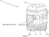
- the pump body or housing 14 may be configured with some arrangement of back side pump ribs 16 that help the liquid sensing device 12 to prevent a malfunction of the pump 10 by avoiding face-to-face contact between an outside housing wall of the pump body or housing 14 and some debris in the liquid or fluid being pumped, e.g., such as a wet towel or other physical interference, that may foul the liquid sensing device 12 and cause it to send a signal for turning the pump 10 ON when there is no presence of water that needs to be pumped.
- the liquid sensing device 12 may sense the liquid in the towel and send the signal for turning the pump 10 ON.
- the pump may also stay ON, which can reduce the pump life, drain the battery of the boat or vessel, and cause other undesirable outcomes as well.
- the liquid sensing device 12 may be configured, mounted or arranged in a back part generally indicated as 18 of the housing 14.
- the major components of the pump 10 may also include a cap plug 10a, a cap 10b, a self tapping screws 10c, a thermal cutoff (TCO) 10d, a motor 10e, a motor mount 10f, a shaft seal 10g, a grommet 10h, wires 10i, an O-ring 10j, an impeller 10k, an inlet pump 10l and a strainer 10m.
- TCO thermal cutoff
- the liquid sensing device 12 may be configured to sense the level of a liquid collecting outside the pump 10 and turn the pump 10 ON/OFF for pumping the liquid.
- the liquid sensing device 12 may take the form of a printed circuit board (PCB) and sensor.
- the PCB may be configured with a capacitive sensing device.
- Printed circuit boards having capacitive sensing devices are known in the art, and the scope of the invention is not intended to be limited to any particular type or kind thereof either now known or later developed in the art.
- the scope of the invention is also not intended to be limited to any particular type or kind of liquid sensing device either now known or later developed in the art, and may include other types or kinds of liquid sensing devices other than printed circuit boards having capacitive sensing devices.
- the pump sensor 12 will determine the pump function ON/OFF by two predefined level sensor represented by bullets labeled A and B. For example, when the water level (bullet C) goes up to a sensor level 2 (bullet A), the sensor 12 will send a signal to the motor 10e and turn the pump 10 ON and make the impeller 10k rotate (bullet E), then water will be pulled by a centrifugal force of the impeller 10k from the inlet pump 10l (bullet 4) to be carried up by a centrifugal motion via and through the pump body cavity (bullet 6) and out the pump outlet (Bullet 7), so as to evacuate all water from the bilge until the water level (Bullet 3) goes down to the sensor level 1 (bullet 2), and then the sensor 12 will send the signal to turn the pump 10 OFF to complete the cycle.
- the sensor 12 will send the signal to turn the pump 10 OFF to complete the cycle.
- the pump sensor 12 may include built-in programming that can sense when the pump 10 is running, but not pumping water to protect the pump, as well as the vessel and the vessel's batteries in which it is being used.
- the PCB may be configured to stop the pump from running, e.g., and begin to check periodically for water entry (such as every 2 1 ⁇ 2 minutes) .
- the pump 10 may be configured to revert to normal operation, e.g., by turning ON when the water reaches approximately 2 1 ⁇ 2" (64 mm) (Sensor Level 2 ( Fig. 2 )) and by shutting OFF the water reaches approximately 5/8" (16 mm) (Sensor Level 1).
- the housing 14 includes a housing wall 20 configured to contain the liquid sensing device 12.
- the housing wall 20 includes an outside wall surface 20a with an outside sensing surface 20b.
- the liquid sensing device 12 inside the housing 14 is mounted in relation to the outside sensing surface 20b.
- the outside sensing surface 20b includes the ribs 16 configured to extent or project outwardly away from the outside wall surface 20a, in order to prevent an object (e.g., having a density different than the liquid density) from being stuck on the outside sensing surface 20b, and allow the liquid sensing device 12 to sense the level of the liquid collecting outside the pump 10 and touching the outside sensing surface 20b, so as to reduce a malfunction of the pump 10 due to the object contacting the outside sensing surface 20b.
- an object e.g., having a density different than the liquid density
- the outside sensing surface 20b is a flat surface, and the ribs 16 are arranged on and project from the flat surface.
- the ribs 16 may be arranged on the flat surface and dimensioned so that there is a space to receive the liquid between adjacent ribs when the object is stuck on, or in contact with, the ribs 16.
- the ribs 16 may be configured to provide heat resistance and structural rigidity to prevent deformation of the outside wall surface 20a from thermal stress.
- the new geometric ribs 16 on the sensing areas help to prevent objects from being stuck on the sensing surface and as a consequence avoid the malfunction of the pumping unit.
- These new ribs form a physical perimeter around the sensor that avoid other object, e.g., including other objects different than a liquid density, to be in touch with the sensor surface 20b.
- these ribs 16 are located on the planar surface perpendicular to bottom of the pump and right at the back side of the pump, e.g., at the opposite side of the water outlet, consistent with that shown in Figures 1 thru 5D of the drawing.
- FIGS 4A thru 4D show an embodiment of a pump 10 of the present invention, e.g., having five (5) ribs 16.
- Figures 5A thru 5D show an embodiment of a pump 100 of the present invention, e.g., having seven (7) ribs 16.
- the ribs 16 are arranged on the outside sensing surface 20b vertically in relation to the pump axis A ( Fig. 4B ), as well as horizontally in relation to the pump axis; the ribs 16 may be symmetrically arranged on the outside sensing surface; or the ribs may include a shorter middle rib and longer outer ribs. Moreover, and by way of example, the ribs 16 may be configured with a contour and a dimension, e.g., consistent with that shown in the drawing.
- the scope of the invention is not intended to be limited to the number of ribs 16, the placement/configuration of the ribs 16, the orientation (e.g., vertical or horizontal) of the ribs 16, the dimension of the ribs 16, etc.; and embodiments are envisioned, and the scope of the invention is intended to include, implementations having a different number of ribs, a different placement/configuration of the ribs, a different orientation (e.g., vertical or horizontal) of the ribs, a different dimension of the ribs, etc., than that shown and described herein.
- This pump is designed to be include in a system with or without bilge float switch and maintain same functionality of this pump.
Landscapes
- Engineering & Computer Science (AREA)
- Mechanical Engineering (AREA)
- General Engineering & Computer Science (AREA)
- Physics & Mathematics (AREA)
- Power Engineering (AREA)
- Thermal Sciences (AREA)
- Fluid Mechanics (AREA)
- Health & Medical Sciences (AREA)
- Life Sciences & Earth Sciences (AREA)
- Hydrology & Water Resources (AREA)
- Public Health (AREA)
- Water Supply & Treatment (AREA)
- General Physics & Mathematics (AREA)
- Electromagnetism (AREA)
- Chemical & Material Sciences (AREA)
- Combustion & Propulsion (AREA)
- Ocean & Marine Engineering (AREA)
- Structures Of Non-Positive Displacement Pumps (AREA)
- Control Of Non-Positive-Displacement Pumps (AREA)
Claims (13)
- Pompe (10)comprenant :un dispositif de détection de liquide (12) intégré à la pompe et configuré pour détecter le niveau d'un liquide s'accumulant à l'extérieur de la pompe (10) et activer/désactiver la pompe (10) pour pomper le liquide ; etun boîtier (14) ayant une paroi de boîtier (20) configurée pour contenir le dispositif de détection de liquide (12), la paroi de boîtier (20) ayant une surface de paroi extérieure (20a) avec une surface de détection extérieure (20b), le dispositif de détection de liquide (12) étant disposé ou monté à l'intérieur du boîtier (14) par rapport à la surface de détection extérieure (20b), afin de permettre au dispositif de détection de liquide (12) de détecter le niveau du liquide s'accumulant à l'extérieur de la pompe (10) et touchant la surface de détection extérieure (20b), caractérisée par le fait que la surface de détection extérieure (20b) comporte des nervures (16) configurées pour s'étendre ou faire saillie vers l'extérieur par rapport à la surface de la paroi extérieure (20a), afin d'empêcher un objet d'être collé sur la surface de détection extérieure (20b), de manière à réduire tout dysfonctionnement de la pompe (10) dû à l'objet entrant en contact avec la surface de détection extérieure (20b), la surface de détection extérieure (20b) étant une surface plane, et les nervures (16) étant disposées sur la surface plane et faisant saillie à partir de cette dernière.
- Pompe selon la revendication 1, dans laquelle les nervures (16) sont disposées sur la surface plane, et dimensionnées de manière à ménager un espace pour recevoir le liquide entre des nervures adjacentes (16) lorsque l'objet est collé sur les nervures (16), ou en contact avec celles-ci.
- Pompe selon la revendication 1, dans laquelle le dispositif de détection de liquide (12) est un dispositif de détection capacitif.
- Pompe selon la revendication 1, dans laquelle le dispositif de détection de liquide (12) est une carte de circuit imprimé comportant un dispositif de détection capacitif.
- Pompe selon la revendication 1, dans laquelle les nervures (16) sont configurées pour fournir une résistance à la chaleur et une rigidité structurelle afin d'empêcher la déformation de la surface de la paroi extérieure (20a) sous l'effet de la contrainte thermique.
- Pompe selon la revendication 1, dans laquelle les nervures (16) incluent cinq (5) nervures.
- Pompe selon la revendication 1, dans laquelle les nervures (16) sont disposées verticalement par rapport à l'axe de la pompe.
- Pompe selon la revendication 1, dans laquelle les nervures (16) sont disposées horizontalement par rapport à l'axe de la pompe.
- Pompe selon la revendication 1, dans laquelle les nervures (16) sont disposées symétriquement sur la surface de détection extérieure (20b).
- Pompe selon la revendication 1, dans laquelle les nervures (16) incluent une nervure centrale (16) plus courte et des nervures extérieures (16) plus longues.
- Pompe selon la revendication 1, dans laquelle les nervures (16) incluent sept (7) nervures.
- Pompe selon la revendication 1, dans laquelle la pompe (10) est une pompe de cale destinée à être installée dans la coque d'un navire et à en pomper le liquide,
ouune pompe de puisard pour configurer et pomper le liquide dans un puisard, ouune pompe de vidange de douche pour configurer et pomper le liquide d'une vidange de douche. - Pompe selon la revendication 1, dans laquelle le dispositif de détection de liquide (12) inclut un capteur de niveau de liquide élevé configuré pour détecter un niveau de liquide élevé et mettre la pompe (10) en marche, et inclut un capteur de niveau de liquide bas configuré pour détecter un niveau de liquide bas et mettre la pompe (10) à l'arrêt.
Applications Claiming Priority (2)
| Application Number | Priority Date | Filing Date | Title |
|---|---|---|---|
| US201762454392P | 2017-02-03 | 2017-02-03 | |
| PCT/US2018/016858 WO2018145000A1 (fr) | 2017-02-03 | 2018-02-05 | Pompe de cale ayant une surface de détection extérieure dotée de nervures |
Publications (4)
| Publication Number | Publication Date |
|---|---|
| EP3577345A1 EP3577345A1 (fr) | 2019-12-11 |
| EP3577345A4 EP3577345A4 (fr) | 2020-11-25 |
| EP3577345C0 EP3577345C0 (fr) | 2024-09-25 |
| EP3577345B1 true EP3577345B1 (fr) | 2024-09-25 |
Family
ID=63038746
Family Applications (1)
| Application Number | Title | Priority Date | Filing Date |
|---|---|---|---|
| EP18748146.0A Active EP3577345B1 (fr) | 2017-02-03 | 2018-02-05 | Pompe de cale ayant une surface de détection extérieure dotée de nervures |
Country Status (8)
| Country | Link |
|---|---|
| US (2) | US20180223863A1 (fr) |
| EP (1) | EP3577345B1 (fr) |
| CN (2) | CN119122822A (fr) |
| AU (1) | AU2018215541B2 (fr) |
| CA (1) | CA3050537C (fr) |
| MX (1) | MX394511B (fr) |
| PL (1) | PL3577345T3 (fr) |
| WO (1) | WO2018145000A1 (fr) |
Families Citing this family (8)
| Publication number | Priority date | Publication date | Assignee | Title |
|---|---|---|---|---|
| EP3875765A1 (fr) * | 2020-03-02 | 2021-09-08 | Husqvarna Ab | Pompe submersible avec capteurs tactiles |
| CN111498006B (zh) * | 2020-04-13 | 2021-02-19 | 武汉理工大学 | 一种适用于豪华邮轮舱底水系统的防空吸装置 |
| US11788535B1 (en) | 2021-02-12 | 2023-10-17 | State Farm Mutual Automobile Insurance Company | Systems and methods for manipulating control of sump pumps to extend lifespans of sump pumps |
| US20230417247A1 (en) * | 2022-05-17 | 2023-12-28 | Milwaukee Electric Tool Corporation | Battery-powered pump |
| CN115247651A (zh) * | 2022-08-03 | 2022-10-28 | 苏州美达斯机电有限公司 | 一种带触控传感器的潜水泵 |
| US11788518B1 (en) | 2023-05-26 | 2023-10-17 | David H. Henry | Low-profile solar-powered flood control device |
| US12465018B1 (en) * | 2024-05-13 | 2025-11-11 | Yubo DONG | Self-circulating pet shower machine |
| USD1117344S1 (en) * | 2024-08-06 | 2026-03-10 | Fujian Aidi Electric Co., Ltd. | Bilge pump |
Family Cites Families (15)
| Publication number | Priority date | Publication date | Assignee | Title |
|---|---|---|---|---|
| GB1544653A (en) * | 1975-11-26 | 1979-04-25 | Nat Marine Service Inc | Interface detector |
| DE3248449A1 (de) * | 1982-01-16 | 1983-07-21 | Jastram-Werke GmbH & Co KG, 2050 Hamburg | Verfahren zur messung des fluessigkeitsspiegels von elektrisch leitenden medien in fluessigkeitsbehaeltern mit sich veraenderndem fluessigkeitsniveau und eine vorrichtung zur durchfuehrung des verfahrens |
| US4645426A (en) * | 1985-04-24 | 1987-02-24 | Hartley E Dale | Bilge pump |
| DE29916252U1 (de) * | 1999-09-17 | 2000-02-10 | Rechner-Industrie-Elektronik GmbH, 68623 Lampertheim | Wegaufnehmer |
| US7373817B2 (en) * | 2004-07-09 | 2008-05-20 | Touchsensor Technologies, Llc | Solid state fluid level sensor |
| WO2006017448A1 (fr) | 2004-08-02 | 2006-02-16 | Environment One Corporation | Reservoirs d’eaux usees et systemes a pompe broyeuse |
| US7025643B1 (en) | 2004-09-24 | 2006-04-11 | Mikulas Csitari | QuickFlush valve kit for flushing and winterizing of cooling system of inboard marine engines, power generators, air-conditioning units, and sailboat engines |
| US7625187B2 (en) * | 2005-08-24 | 2009-12-01 | Johnson Pumps Of America Inc. | Submersible pump with integrated liquid level sensing and control system |
| US20110110792A1 (en) * | 2009-11-12 | 2011-05-12 | Joseph Kendall Mauro | Sensors and methods and apparatus relating to same |
| US20110110794A1 (en) * | 2009-11-12 | 2011-05-12 | Philip Mayleben | Sensors and methods and apparatus relating to same |
| US9410545B2 (en) * | 2011-06-02 | 2016-08-09 | Lake Red Rock Llc | Solid state bilge pump switch |
| SE537872C2 (sv) * | 2011-12-22 | 2015-11-03 | Xylem Ip Holdings Llc | Metod för styrning av ett pumparrangemang |
| US9719515B2 (en) * | 2013-01-11 | 2017-08-01 | Liberty Pumps, Inc. | Liquid pump |
| CN204572414U (zh) * | 2015-04-30 | 2015-08-19 | 君禾泵业股份有限公司 | 潜水泵 |
| CN105020112B (zh) * | 2015-07-13 | 2017-11-03 | 兰州空间技术物理研究所 | 一种高热稳定的离子推力器屏栅筒 |
-
2018
- 2018-02-05 CN CN202411197208.7A patent/CN119122822A/zh active Pending
- 2018-02-05 CN CN201880009500.8A patent/CN110234885A/zh active Pending
- 2018-02-05 EP EP18748146.0A patent/EP3577345B1/fr active Active
- 2018-02-05 PL PL18748146.0T patent/PL3577345T3/pl unknown
- 2018-02-05 MX MX2019009234A patent/MX394511B/es unknown
- 2018-02-05 CA CA3050537A patent/CA3050537C/fr active Active
- 2018-02-05 AU AU2018215541A patent/AU2018215541B2/en active Active
- 2018-02-05 WO PCT/US2018/016858 patent/WO2018145000A1/fr not_active Ceased
- 2018-02-05 US US15/888,648 patent/US20180223863A1/en not_active Abandoned
-
2021
- 2021-11-09 US US17/522,112 patent/US20220136523A1/en active Pending
Also Published As
| Publication number | Publication date |
|---|---|
| CA3050537C (fr) | 2025-05-13 |
| AU2018215541A1 (en) | 2019-08-08 |
| CN110234885A (zh) | 2019-09-13 |
| WO2018145000A1 (fr) | 2018-08-09 |
| CN119122822A (zh) | 2024-12-13 |
| MX2019009234A (es) | 2019-09-19 |
| US20220136523A1 (en) | 2022-05-05 |
| US20180223863A1 (en) | 2018-08-09 |
| EP3577345A1 (fr) | 2019-12-11 |
| EP3577345C0 (fr) | 2024-09-25 |
| CA3050537A1 (fr) | 2018-08-09 |
| PL3577345T3 (pl) | 2025-04-14 |
| AU2018215541B2 (en) | 2023-02-02 |
| MX394511B (es) | 2025-03-24 |
| EP3577345A4 (fr) | 2020-11-25 |
Similar Documents
| Publication | Publication Date | Title |
|---|---|---|
| EP3577345B1 (fr) | Pompe de cale ayant une surface de détection extérieure dotée de nervures | |
| US7264449B1 (en) | Automatic liquid collection and disposal assembly | |
| US5028910A (en) | Drain overflow alarm | |
| EP2715242B1 (fr) | Dispositif de collecte de condensat | |
| US8657583B2 (en) | Centrifugal pump with coaxial inlet and outlet and liquid level detector | |
| WO2011075324A1 (fr) | Pompe à condensat | |
| US20090123295A1 (en) | Sump pump activation switch | |
| CN102705265A (zh) | 空调机用排水泵 | |
| EP2363540A2 (fr) | Bac de douche automatique ou rigole de salle d'eau | |
| EP2861374B1 (fr) | Technique permettant d'empêcher une poche d'air au moyen d'un démarrage instable et d'une fente de libération d'air pour des pompes | |
| US7972117B1 (en) | Pump control system for submersible pumps | |
| CN106704213B (zh) | 冷凝泵总成 | |
| US20140339174A1 (en) | Method of monitoring a fluid level within a fluid volume | |
| EP4567281A1 (fr) | Système de pompe à régulation dynamique de niveau | |
| KR101800972B1 (ko) | 취수용 펌프 제어시스템 | |
| JP2008223574A (ja) | キャンドポンプ | |
| WO2006105017A2 (fr) | Pompe de recuperation des eaux condensees | |
| CN218407706U (zh) | 一种带液位监控功能的空调排水泵 | |
| JP2002054591A (ja) | 水中モータポンプ及びその自動発停方法 | |
| KR20080103731A (ko) | 입형 다단 펌프의 공회전 방지 시스템 | |
| JP2004218576A (ja) | 竪型水中電動ポンプの浸水検知機構 | |
| US20100189570A1 (en) | Intelligent auto-sensing pumping device | |
| US12366082B1 (en) | Handheld swimming pool sewage suction machine | |
| CN215176245U (zh) | 制冰机 | |
| KR101206866B1 (ko) | 압력 스위치를 이용한 수중 펌프 장치 |
Legal Events
| Date | Code | Title | Description |
|---|---|---|---|
| STAA | Information on the status of an ep patent application or granted ep patent |
Free format text: STATUS: THE INTERNATIONAL PUBLICATION HAS BEEN MADE |
|
| PUAI | Public reference made under article 153(3) epc to a published international application that has entered the european phase |
Free format text: ORIGINAL CODE: 0009012 |
|
| STAA | Information on the status of an ep patent application or granted ep patent |
Free format text: STATUS: REQUEST FOR EXAMINATION WAS MADE |
|
| 17P | Request for examination filed |
Effective date: 20190730 |
|
| AK | Designated contracting states |
Kind code of ref document: A1 Designated state(s): AL AT BE BG CH CY CZ DE DK EE ES FI FR GB GR HR HU IE IS IT LI LT LU LV MC MK MT NL NO PL PT RO RS SE SI SK SM TR |
|
| A4 | Supplementary search report drawn up and despatched |
Effective date: 20201022 |
|
| RIC1 | Information provided on ipc code assigned before grant |
Ipc: F04D 13/16 20060101AFI20201016BHEP Ipc: F04D 15/02 20060101ALI20201016BHEP |
|
| STAA | Information on the status of an ep patent application or granted ep patent |
Free format text: STATUS: EXAMINATION IS IN PROGRESS |
|
| 17Q | First examination report despatched |
Effective date: 20220811 |
|
| GRAP | Despatch of communication of intention to grant a patent |
Free format text: ORIGINAL CODE: EPIDOSNIGR1 |
|
| STAA | Information on the status of an ep patent application or granted ep patent |
Free format text: STATUS: GRANT OF PATENT IS INTENDED |
|
| INTG | Intention to grant announced |
Effective date: 20240419 |
|
| GRAS | Grant fee paid |
Free format text: ORIGINAL CODE: EPIDOSNIGR3 |
|
| GRAA | (expected) grant |
Free format text: ORIGINAL CODE: 0009210 |
|
| STAA | Information on the status of an ep patent application or granted ep patent |
Free format text: STATUS: THE PATENT HAS BEEN GRANTED |
|
| AK | Designated contracting states |
Kind code of ref document: B1 Designated state(s): AL AT BE BG CH CY CZ DE DK EE ES FI FR GB GR HR HU IE IS IT LI LT LU LV MC MK MT NL NO PL PT RO RS SE SI SK SM TR |
|
| REG | Reference to a national code |
Ref country code: GB Ref legal event code: FG4D |
|
| REG | Reference to a national code |
Ref country code: CH Ref legal event code: EP |
|
| REG | Reference to a national code |
Ref country code: DE Ref legal event code: R096 Ref document number: 602018074710 Country of ref document: DE |
|
| REG | Reference to a national code |
Ref country code: IE Ref legal event code: FG4D |
|
| U01 | Request for unitary effect filed |
Effective date: 20241023 |
|
| U07 | Unitary effect registered |
Designated state(s): AT BE BG DE DK EE FI FR IT LT LU LV MT NL PT RO SE SI Effective date: 20241105 |
|
| PG25 | Lapsed in a contracting state [announced via postgrant information from national office to epo] |
Ref country code: NO Free format text: LAPSE BECAUSE OF FAILURE TO SUBMIT A TRANSLATION OF THE DESCRIPTION OR TO PAY THE FEE WITHIN THE PRESCRIBED TIME-LIMIT Effective date: 20241225 |
|
| PG25 | Lapsed in a contracting state [announced via postgrant information from national office to epo] |
Ref country code: GR Free format text: LAPSE BECAUSE OF FAILURE TO SUBMIT A TRANSLATION OF THE DESCRIPTION OR TO PAY THE FEE WITHIN THE PRESCRIBED TIME-LIMIT Effective date: 20241226 |
|
| PG25 | Lapsed in a contracting state [announced via postgrant information from national office to epo] |
Ref country code: RS Free format text: LAPSE BECAUSE OF FAILURE TO SUBMIT A TRANSLATION OF THE DESCRIPTION OR TO PAY THE FEE WITHIN THE PRESCRIBED TIME-LIMIT Effective date: 20241225 |
|
| PG25 | Lapsed in a contracting state [announced via postgrant information from national office to epo] |
Ref country code: RS Free format text: LAPSE BECAUSE OF FAILURE TO SUBMIT A TRANSLATION OF THE DESCRIPTION OR TO PAY THE FEE WITHIN THE PRESCRIBED TIME-LIMIT Effective date: 20241225 Ref country code: NO Free format text: LAPSE BECAUSE OF FAILURE TO SUBMIT A TRANSLATION OF THE DESCRIPTION OR TO PAY THE FEE WITHIN THE PRESCRIBED TIME-LIMIT Effective date: 20241225 Ref country code: GR Free format text: LAPSE BECAUSE OF FAILURE TO SUBMIT A TRANSLATION OF THE DESCRIPTION OR TO PAY THE FEE WITHIN THE PRESCRIBED TIME-LIMIT Effective date: 20241226 |
|
| U20 | Renewal fee for the european patent with unitary effect paid |
Year of fee payment: 8 Effective date: 20250227 |
|
| PG25 | Lapsed in a contracting state [announced via postgrant information from national office to epo] |
Ref country code: IS Free format text: LAPSE BECAUSE OF FAILURE TO SUBMIT A TRANSLATION OF THE DESCRIPTION OR TO PAY THE FEE WITHIN THE PRESCRIBED TIME-LIMIT Effective date: 20250125 |
|
| PG25 | Lapsed in a contracting state [announced via postgrant information from national office to epo] |
Ref country code: SM Free format text: LAPSE BECAUSE OF FAILURE TO SUBMIT A TRANSLATION OF THE DESCRIPTION OR TO PAY THE FEE WITHIN THE PRESCRIBED TIME-LIMIT Effective date: 20240925 |
|
| PG25 | Lapsed in a contracting state [announced via postgrant information from national office to epo] |
Ref country code: ES Free format text: LAPSE BECAUSE OF FAILURE TO SUBMIT A TRANSLATION OF THE DESCRIPTION OR TO PAY THE FEE WITHIN THE PRESCRIBED TIME-LIMIT Effective date: 20240925 |
|
| PG25 | Lapsed in a contracting state [announced via postgrant information from national office to epo] |
Ref country code: CZ Free format text: LAPSE BECAUSE OF FAILURE TO SUBMIT A TRANSLATION OF THE DESCRIPTION OR TO PAY THE FEE WITHIN THE PRESCRIBED TIME-LIMIT Effective date: 20240925 |
|
| PG25 | Lapsed in a contracting state [announced via postgrant information from national office to epo] |
Ref country code: SK Free format text: LAPSE BECAUSE OF FAILURE TO SUBMIT A TRANSLATION OF THE DESCRIPTION OR TO PAY THE FEE WITHIN THE PRESCRIBED TIME-LIMIT Effective date: 20240925 |
|
| PLBE | No opposition filed within time limit |
Free format text: ORIGINAL CODE: 0009261 |
|
| STAA | Information on the status of an ep patent application or granted ep patent |
Free format text: STATUS: NO OPPOSITION FILED WITHIN TIME LIMIT |
|
| 26N | No opposition filed |
Effective date: 20250626 |
|
| PG25 | Lapsed in a contracting state [announced via postgrant information from national office to epo] |
Ref country code: MC Free format text: LAPSE BECAUSE OF FAILURE TO SUBMIT A TRANSLATION OF THE DESCRIPTION OR TO PAY THE FEE WITHIN THE PRESCRIBED TIME-LIMIT Effective date: 20240925 |
|
| REG | Reference to a national code |
Ref country code: CH Ref legal event code: PL |
|
| PG25 | Lapsed in a contracting state [announced via postgrant information from national office to epo] |
Ref country code: CH Free format text: LAPSE BECAUSE OF NON-PAYMENT OF DUE FEES Effective date: 20250228 |
|
| PG25 | Lapsed in a contracting state [announced via postgrant information from national office to epo] |
Ref country code: HR Free format text: LAPSE BECAUSE OF FAILURE TO SUBMIT A TRANSLATION OF THE DESCRIPTION OR TO PAY THE FEE WITHIN THE PRESCRIBED TIME-LIMIT Effective date: 20240925 |
|
| PG25 | Lapsed in a contracting state [announced via postgrant information from national office to epo] |
Ref country code: IE Free format text: LAPSE BECAUSE OF NON-PAYMENT OF DUE FEES Effective date: 20250205 |
|
| U20 | Renewal fee for the european patent with unitary effect paid |
Year of fee payment: 9 Effective date: 20260227 |
|
| PGFP | Annual fee paid to national office [announced via postgrant information from national office to epo] |
Ref country code: GB Payment date: 20260227 Year of fee payment: 9 |
|
| PGFP | Annual fee paid to national office [announced via postgrant information from national office to epo] |
Ref country code: PL Payment date: 20260122 Year of fee payment: 9 |