EP3577370B1 - Hydraulisch verstellbare riemenscheibe für ein stufenloses getriebe - Google Patents
Hydraulisch verstellbare riemenscheibe für ein stufenloses getriebe Download PDFInfo
- Publication number
- EP3577370B1 EP3577370B1 EP18726318.1A EP18726318A EP3577370B1 EP 3577370 B1 EP3577370 B1 EP 3577370B1 EP 18726318 A EP18726318 A EP 18726318A EP 3577370 B1 EP3577370 B1 EP 3577370B1
- Authority
- EP
- European Patent Office
- Prior art keywords
- pulley
- piston
- valve
- plug
- hydraulically
- Prior art date
- Legal status (The legal status is an assumption and is not a legal conclusion. Google has not performed a legal analysis and makes no representation as to the accuracy of the status listed.)
- Active
Links
- 230000005540 biological transmission Effects 0.000 title claims description 24
- 239000012530 fluid Substances 0.000 description 28
- 238000007789 sealing Methods 0.000 description 6
- 230000001965 increasing effect Effects 0.000 description 4
- 239000002184 metal Substances 0.000 description 3
- 230000002708 enhancing effect Effects 0.000 description 2
- 230000003247 decreasing effect Effects 0.000 description 1
- 230000001627 detrimental effect Effects 0.000 description 1
- 238000007599 discharging Methods 0.000 description 1
- 238000000034 method Methods 0.000 description 1
- 238000012986 modification Methods 0.000 description 1
- 230000004048 modification Effects 0.000 description 1
Images

Classifications
-
- F—MECHANICAL ENGINEERING; LIGHTING; HEATING; WEAPONS; BLASTING
- F16—ENGINEERING ELEMENTS AND UNITS; GENERAL MEASURES FOR PRODUCING AND MAINTAINING EFFECTIVE FUNCTIONING OF MACHINES OR INSTALLATIONS; THERMAL INSULATION IN GENERAL
- F16H—GEARING
- F16H55/00—Elements with teeth or friction surfaces for conveying motion; Worms, pulleys or sheaves for gearing mechanisms
- F16H55/32—Friction members
- F16H55/52—Pulleys or friction discs of adjustable construction
- F16H55/56—Pulleys or friction discs of adjustable construction of which the bearing parts are relatively axially adjustable
-
- F—MECHANICAL ENGINEERING; LIGHTING; HEATING; WEAPONS; BLASTING
- F16—ENGINEERING ELEMENTS AND UNITS; GENERAL MEASURES FOR PRODUCING AND MAINTAINING EFFECTIVE FUNCTIONING OF MACHINES OR INSTALLATIONS; THERMAL INSULATION IN GENERAL
- F16H—GEARING
- F16H61/00—Control functions within control units of change-speed- or reversing-gearings for conveying rotary motion ; Control of exclusively fluid gearing, friction gearing, gearings with endless flexible members or other particular types of gearing
- F16H61/0003—Arrangement or mounting of elements of the control apparatus, e.g. valve assemblies or snapfittings of valves; Arrangements of the control unit on or in the transmission gearbox
- F16H61/0009—Hydraulic control units for transmission control, e.g. assembly of valve plates or valve units
-
- F—MECHANICAL ENGINEERING; LIGHTING; HEATING; WEAPONS; BLASTING
- F16—ENGINEERING ELEMENTS AND UNITS; GENERAL MEASURES FOR PRODUCING AND MAINTAINING EFFECTIVE FUNCTIONING OF MACHINES OR INSTALLATIONS; THERMAL INSULATION IN GENERAL
- F16H—GEARING
- F16H61/00—Control functions within control units of change-speed- or reversing-gearings for conveying rotary motion ; Control of exclusively fluid gearing, friction gearing, gearings with endless flexible members or other particular types of gearing
- F16H61/66—Control functions within control units of change-speed- or reversing-gearings for conveying rotary motion ; Control of exclusively fluid gearing, friction gearing, gearings with endless flexible members or other particular types of gearing specially adapted for continuously variable gearings
- F16H61/662—Control functions within control units of change-speed- or reversing-gearings for conveying rotary motion ; Control of exclusively fluid gearing, friction gearing, gearings with endless flexible members or other particular types of gearing specially adapted for continuously variable gearings with endless flexible members
- F16H61/66272—Control functions within control units of change-speed- or reversing-gearings for conveying rotary motion ; Control of exclusively fluid gearing, friction gearing, gearings with endless flexible members or other particular types of gearing specially adapted for continuously variable gearings with endless flexible members characterised by means for controlling the torque transmitting capability of the gearing
Definitions
- the present disclosure relates to a hydraulically adjustable pulley device for a continuously variable transmission, as defined in the preamble of the claim 1 hereinafter.
- Such pulley and transmission are generally known in the art, for example from the Japanese patent publication JP 2010-002044 A1 .
- the known transmission includes two pulleys, i.e. both a primary or driving pulley coupled to a prime mover and a secondary or driven pulley coupled to a load, in particular to the driven wheels of a motor vehicle.
- Each such pulley comprises two (frusto-)conical discs arranged on a shaft and hydraulically operable adjustment means that serve to mutually urge the discs towards each other in axial direction.
- a drive belt such as a metal push belt, a metal drive chain or a fibre-reinforced rubber pull belt, is wrapped around the pulleys, located (in part) between the discs thereof.
- the drive belt is clamped between the two discs of both pulleys such that the rotation of one pulley is transmitted to the other one pulley.
- a radius of curvature of the drive belt at each pulley, between the discs thereof is controlled.
- these radii of curvature in particular by the ratio there between, determine a speed ratio and a torque ratio of the transmission, which ratios can thus be controlled to an arbitrary value within a range of ratios determined by the transmission design through an appropriate actuation of the pulley adjustment means.
- the pulley adjustment means of either pulley comprise a piston/cylinder-assembly, whereof the piston is fixed to the pulley shaft and whereof the cylinder contains the piston in radial direction and is fixed to an axial side of a first pulley disc opposite the other, second pulley disc, which first pulley disc is mounted axially movable by being provided with a sleeve that is fitted around the pulley shaft.
- the known pulley valve comprises a ball-shaped plug that is pressed into a circular seat by a spring of the pulley valve, in order to close an opening defined by and radially inside such plug seat. Furthermore, the pulley valve is provided with a plunger that engages the plug in the opposite direction relative to the force exerted on the plug by the plug spring.
- the plunger is shaped as a hollow tube with a circular cross-section that narrowly fits inside the plug seat.
- the plunger is arranged axially movable in the pulley shaft channel, activated by a hydraulic control pressure, such that it can lift, i.e. push the plug of its seat to open the pulley valve and channel. Furthermore, at the axial side thereof that engages the plug, the plunger is provided with holes, such that when the plunger has lifted the plug of its seat, hydraulic fluid can flow through the pulley valve via these holes and the radial inside of the plunger.
- JP 2010-014200 A1 provides an alternative, known design of the pulley valve, in particular in terms of the plunger thereof.
- the end of the plunger that engages the plug is shaped as a rod, whereas the opposite end of the plunger is shaped as a tube.
- These plunger ends are mutually connected by a number of ribs extending between them in radial direction. In this case, hydraulic fluid can flow through the pulley valve via these holes between the ribs.
- the speed ratio of the transmission can be changed quickly, i.e. to restrict the flow of hydraulic fluid into and from of the pulley cylinder chambers as little as possible.
- the fluid flow away from the pulley cylinder chamber, i.e. the discharge of hydraulic fluid from such chamber is, however, limited by the cross-sectional area of the said holes of the plunger.
- the present disclosure provides for a novel design of the pulley valve that -when it is open/opened- favourably allows for a relatively large fluid flow towards and away from the pulley cylinder chamber.
- a piston plug, a plug seat and a plug spring are contained in a hollow cylindrical piston that is provided with a stepped outside diameter and that is arranged axially moveable in a housing, i.e. casing of the pulley valve.
- the plug spring is arranged to exert a force on piston plug for urging it into, or at least towards the plug seat.
- the plug spring can be fitted between the piston plug and the valve casing, it is preferably fitted between the piston plug and valve piston, such that such spring force is independent of a movement of the valve piston relative to the valve casing.
- the valve casing is provided with an inwardly protruding abutment edge for interacting in a sealing manner with a smaller diameter side of the valve piston, while limiting the axial movement thereof relative to the valve casing.
- a further spring i.e. a piston spring is fitted between the piston and the valve casing for urging the piston against, or at least towards the said abutment edge of valve casing.
- a hydraulic pocket is present in-between the said abutment edge of the valve casing, the said smaller diameter side of the valve piston and a shoulder of that valve piston between the smaller and larger diameter sides thereof.
- the smaller diameter side of the piston is pierced through, providing a hydraulic connection of limited flow capacity, i.e. a hydraulic choke, between the hydraulic pocket and the inside of the piston that contains the piston plug.
- the pulley valve is provided with means, such as an axially movable plunger, that can be operated to push the piston plug of its seat inside the piston.
- This novel pulley valve has the advantage that, after it is initially opened for discharging hydraulic fluid from the pulley cylinder chamber by pushing, i.e. lifting the piston plug of its seat inside the piston, the piston as whole will lift of the abutment edge of valve casing under influence of a pressure difference between the inside of the valve piston and in the hydraulic pocket.
- a favourably large opening between the valve casing and the piston becomes available for the said discharge of hydraulic fluid, in particular in comparison with the opening provided by the holes of the plunger in the known pulley valve.
- the opening available for the said discharge of hydraulic fluid could also be increased by increasing the size, in particular the (inner) diameter of the plug seat.
- the diameter of the piston plug has to be increased accordingly, resulting in a corresponding increase of the force required to push the piston plug of its seat by the plunger against the forces exerted thereon by both the plug spring and the pulley cylinder pressure that prevails (also) inside valve piston and thus severely complicating the design and/or the operation thereof.
- the known continuously variable transmission is depicted with an input or primary shaft 1 and with an output or secondary shaft 2.
- the known transmission is intended to be incorporated between an engine E and a load L for varying the transmission speed ratio there between within a continuous range of possible speed ratios.
- the known transmission includes two hydraulically adjustable pulleys 3 and 4, i.e. both a primary, i.e. driving pulley 3 to be driven by the engine E via the transmission input shaft 2 and a secondary, i.e. driven pulley 4 to drive a driven wheel (L) of a motor vehicle.
- a drive belt 5, such as a metal push belt, is wrapped around and in frictional contact with the pulleys 3, 4.
- An electro-hydraulic control system is provided to hydraulically adjust the pulleys 3, 4 by way of controlling the hydraulic pressure in a cylinder chamber 7 of a piston/cylinder-assembly of each respective pulley 3, 4, in particular to control the transmission speed ratio and the friction between the drive belt 5 and the pulleys 3, 4.
- the control system of the known transmission includes at least a pump 8, for the supply of a flow of pressurised hydraulic fluid from a reservoir of hydraulic fluid 9, and a valve system 50.
- the known pulley 3, 4 is shown to comprise a pulley shaft 10 rotatably born by bearings 11 and provided with two (frusto-)conical discs 12 and 13.
- a first pulley disc 12 is immovably fixed to, possibly integral with the pulley shaft 10.
- a second pulley disc 13 is fitted axially displaceable, i.e. moveable on the pulley shaft 10 by being provided with a sleeve 14 that is fitted on and around the pulley shaft with a radial clearance.
- the moveable pulley disc 13 and its sleeve 14 are typically locked relative to the pulley shaft 10 in rotational direction by means of a spline connection (not shown).
- the moveable pulley disc 13 can be moved or at least urged toward the other, fixed pulley disc 12 by exerting a hydraulic pressure in a cylinder chamber 7 of a piston/cylinder-assembly 15, 16 of the respective pulley 3, 4 and whereof a cylinder 15 is fixed to the moveable pulley disc 13 and a piston 16 is fixed to the pulley shaft 10.
- a sealing ring 17 is that favourably prevents, or at least reduces, the leakage of hydraulic fluid from the cylinder chamber 7.
- the cylinder chamber 7 is connected to a hydraulic line 18 of the electro-hydraulic control system 6 that is external to the pulley 3, 4, via a radially oriented bore 19 and an axially oriented channel 20 of the pulley shaft 10.
- a hydraulic connection 21 is provided between the pulley shaft channel 20 of the rotatable pulley shaft 10 and the said external line 18 that is external to the pulley 3, 4, i.e. that is stationary relative to the pulley shaft 10.
- the hydraulic connection 21 includes a cylindrically shaped section that is inserted in the pulley shaft channel 20 and a sealing ring 22 arranged on and around the outer circumference of the said cylindrically shaped section.
- a valve 23 is provided in the pulley shaft channel 20.
- Such pulley valve 23 is designed and arranged to close when no hydraulic fluid is to be supplied to or discharged from the cylinder chamber 7.
- the pulley valve 23 is closed, the said hydraulic connection 21 can be depressurised and the said detrimental leakage can be reduced, at least on average during operation of the transmission.
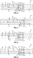
- FIGs 3 to 6 illustrate the design and working principle of a novel design of the pulley valve 23 in a schematic cross-sectional view thereof in accordance with the present disclosure.
- the novel pulley valve 23 is shown to comprise a valve casing 24 that defines an internal channel 25 for hydraulic fluid that is hydraulically connected to the said external line 18 and to the said radial bore 19.
- the valve casing 24 is preferably embodied by the pulley shaft 10 and the said internal channel 25 preferably embodies the pulley shaft channel 20 thereof.
- a hollow cylindrical valve piston 26 is provided that is axially moveable relative to the valve casing 24.
- the valve piston 26 includes a first axial side 27 having a relatively small outer diameter and a second axial side 28 having a relatively large outer diameter, between which axial sides 27, 28 the piston 26 includes a shoulder 29.
- valve piston 26 The axial movement of the valve piston 26 is biased towards an inwardly protruding abutment edge 30 of the valve casing 24 by means of a piston spring 31 provided between the valve casing 24 and the valve piston 26.
- the valve piston 26 and the abutment edge 30 of the valve casing 24 are designed to provide a hydraulic seal between the said internal channel 25 and the said radial bore 19 when the piston 26 rests against the abutment edge 30.
- a hydraulic pocket 32 is defined by and between the said abutment edge 30 of the valve casing 24, the smaller diameter side 27 of the valve piston 26 and the piston shoulder 29.
- the valve piston 26 encloses a piston chamber 33, wherein a piston plug 34, a plug seat 35 circumscribing an opening 36 and a plug spring 37 are contained.
- the piston plug 34 is axially moveable relative to the valve piston 26, but is biased towards the plug seat 35 by the plug spring 37 that is thereto arranged between the valve piston 26 and the piston plug 34.
- the piston plug 34 and the plug seat 35 are designed to provide a hydraulic seal between the said internal channel 25 and the piston chamber 33 when the piston plug 34 rests on the plug seat 35.
- the piston chamber 33 is in direct hydraulic connection with the hydraulic pocket 32 via a channel 38 piercing through in the wall of the valve piston 26 and having a relatively small cross-sectional surface area in relation to its length, i.e. a choke 38.
- valve piston 26 of the novel pulley valve 23 is moveable relative to the valve casing 24 and the abutment edge 30 thereof, for opening and closing a relatively large passage for hydraulic fluid between the cylinder chamber 7 and the external line 18, whereas the valve piston 26 itself includes a piston plug 34 that is moveable relative to the plug seat 35 thereof, for opening and closing a relatively small passage for hydraulic fluid.
- the novel pulley valve 23 further comprises an axially movable plunger 39 that can be activated by applying a hydraulic control pressure in a control cylinder 40 of the pulley valve 23 to lift the piston plug 34 of its plug seat 35 and thus to open a direct hydraulic connection between the said internal channel 25 and the piston chamber 33 thereof.
- a hydraulic control pressure in a control cylinder 40 of the pulley valve 23 to lift the piston plug 34 of its plug seat 35 and thus to open a direct hydraulic connection between the said internal channel 25 and the piston chamber 33 thereof.
- a plunger return spring 41 is provided to return the plunger 39 to its inactive position out of contact with the piston plug 34 when the plunger control pressure is removed, at least essentially. During such return of the plunger 39, air is draw in behind it via the said further channel 42 in the valve casing 24.
- the novel pulley valve 23 is illustrated in its closed state.
- This closed state is entered into and/or prevails when both the hydraulic pressure in the internal channel 25 and the hydraulic pressure in the hydraulic pocket 32 are essentially equal to or lower than the hydraulic pressure in the piston chamber 33.
- the hydraulic pressures in the piston chamber 33 and in the hydraulic pocket 32 are equal to one another, since these communicate with one another via the choke 38.
- the valve piston 26 and the piston plug 34 are pressed in firm, sealing contact with, respectively, the abutment edge 30 of the valve casing 24 and the plug seat 35 under influence of the said pressure difference and the force exerted by, respectively, the piston spring 31 and the plug spring 37.
- the hydraulic pressure in the pulley cylinder chamber 7 is essentially maintained at its desired, constant level, while simultaneously the pressure level in the said external line 18 and in the said hydraulic connection 21 can be favourably reduced to zero, at least essentially.
- the novel pulley valve 23 is illustrated in its supply state.
- this supply state thereof occurs when the hydraulic pressure in the internal channel 25 is raised to above the hydraulic pressure in the piston chamber 33.
- the valve piston 26 is lifted of the abutment edge 30 against the forces exerted by the hydraulic pressure in the piston chamber 33 and by the piston spring 31.
- a gap is formed between the inwardly abutment edge 30 and the said first axial side 27 of the valve piston 26.
- the valve plug 34 remains seated in the piston seat 35 by the force exerted by the plug spring 37.
- hydraulic fluid is supplied from the said external line 18 and the internal channel 25 via the said gap between the inwardly abutment edge 30 and the said first axial side 27 of the valve piston 26 to the said radial bore 19 and into the pulley cylinder chamber 7 to increase the pulley cylinder pressure and/or to move the moveable pulley disc 13 toward the fixed pulley disc 12.
- the pressure level in the pulley cylinder chamber 7 has increased to (essentially) the pressure level in the internal channel 25, the valve piston 26 returns to rest on the abutment edge 30 of the valve casing 24 by the force exerted by the piston spring 35 and the valve 23. Thereafter, the internal channel 25 can (again) be depressurised to return to the, efficiency enhancing, closed state of the novel pulley valve 23.
- the novel pulley valve 23 is illustrated in its initial discharge state.
- this initial discharge state thereof the plunger 39 is activated by applying the plunger control pressure in the control cylinder 40 to lift the piston plug 34 of its plug seat 35.
- hydraulic fluid flows from the piston chamber 33 via the opening 36 defined inside the plug seat 35 into the internal channel 25, whereby these respective hydraulic pressures are equalized, i.e. whereby the hydraulic pressure in the piston chamber 33 is decreased.
- hydraulic fluid also flows from the hydraulic pocket 32 via the choke 38 into the piston chamber 33.
- the pressure level in the hydraulic pocket 32 remains higher than the pressure level in the piston chamber 33.
- valve piston 26 In these pressure conditions, the valve piston 26 is lifted of the abutment edge 30 of the valve casing 24 by the hydraulic pressure in the hydraulic pocket 32 acting on the piston shoulder 29 against the force exerted by the piston spring 31.
- the gap between the inwardly abutment edge 30 and the said first axial side 27 of the valve piston 26 is formed.
- This latter state of the novel pulley valve 23 is denoted the final discharge state and is illustrated in figure 6 .
- the gap between the inwardly abutment edge 30 and the valve piston 26 is available for the discharge of hydraulic fluid from the pulley cylinder chamber 7 into the said external line 18.
- This gap is large in comparison with the said opening 36 of the valve piston 26, such that a favourably large discharge flow is allowed thereby.
- Such discharge of hydraulic fluid form the pulley cylinder chamber 7 serves to decrease the pulley cylinder pressure and/or allows the moveable pulley disc 13 to move away from the fixed pulley disc 12.
- the pressure level in the pulley cylinder chamber 7 has reduced to (essentially) the pressure level in the internal channel 25, the valve piston 26 returns to rest on the abutment edge 30 of the valve casing 24 by the force exerted by the piston spring 35.
- the plunger control pressure is removed to allow the plunger 39 to be deactivated by the plunger return spring 41. Thereafter, the internal channel 25 can (again) be depressurised to return to the, efficiency enhancing, closed state of the novel pulley valve 23.
- the plunger 39 is activated against the force of the return spring 41 to push the piston plug 34 of its plug seat 30 by exerting a pressure in the control cylinder 40 and is returned to its in active state by the return spring 41 when such plunger control pressure is removed, at least is insufficient to overcome the said force of the return spring 41. It is, however, also possible to arrange the (return) spring 41 and the control cylinder 40 oppositely relative to the plunger 39.
- the plunger would be activated to push the piston plug of its plug seat by the force of the spring and would be returned to its inactive state against the force of the spring by exerting and continuing to exert a (sufficient) plunger control pressure in the control cylinder.
- This latter embodiment of the pulley valve has the advantage that it remains open, i.e. that the pulley cylinder chamber 7 remains connected to the said external line 18 and controllable, also in case the plunger control pressure can inadvertently not be generated by the control system, e.g. due to a failure thereof.
- the effectiveness of the novel pulley valve 23 can be improved by providing the known pulley 3, 4 with a further sealing ring 51 between the sleeve 14 of the axially moveable pulley disc 13 and the pulley shaft 10 thereof, as illustrated in figure 2 .
- a clearance between such pulley sleeve 14 and pulley shaft 10 is bridged, preventing, or at least reducing the leakage of hydraulic fluid from the cylinder chamber 7 via such clearance.
- the pulley cylinder pressure can be maintained for longer and the hydraulic connection 21 needs to be pressurised and the pulley valve 23 needs to be opened favourably less frequently.
Landscapes
- Engineering & Computer Science (AREA)
- General Engineering & Computer Science (AREA)
- Mechanical Engineering (AREA)
- Transmissions By Endless Flexible Members (AREA)
Claims (6)
- Hydraulisch verstellbare Riemenscheibe (3; 4) für ein stufenloses Getriebe mit zwei Riemenscheiben (3, 4) und einem Antriebsriemen (5), wobei die Riemenscheibe (3; 4) mit zwei Riemenscheibentellern (12, 13) auf einer Riemenscheibenwelle (10) versehen ist, von denen mindestens ein Riemenscheibenteller (13) auf der Riemenscheibenwelle (10) beweglich ist, an der die Riemenscheibe (3; 4) mit einer Kolben/Zylinder-Anordnung (15, 16) vorgesehen ist, die eine Zylinderkammer (7) umfasst, wobei die Zylinderkammer (7) mit einem äußeren Kanal (18) des Getriebes durch einen inneren Kanal (20; 25) der Riemenscheibenwelle (10) verbunden ist oder zumindest verbunden sein kann, wobei die Riemenscheibe (3; 4) ferner mit einem Riemenscheibenventil (23) versehen ist, das dahingehend zwischen der Zylinderkammer (7) und dem äußeren Kanal (18) angeordnet ist, diese selektiv hydraulisch zu verbinden oder hydraulisch zu trennen, wobei das Riemenscheibenventil (23) ein Ventilgehäuse (24), einen Kolbenstopfen (34), einen Stopfensitz (35), der eine Strömungsöffnung (36) umgibt, und einen Stößel (39) umfasst, wobei der Stößel (39) bezüglich des Stopfensitzes (35) derart beweglich ist, dass er sich entweder durch die Strömungsöffnung (36) erstrecken kann, um den Kolbenstopfen (35) aus dem Stopfensitz (35) zu drücken, oder davon zurückgezogen werden kann, um zu gestatten, dass der Kolbenstopfen (35) auf dem Stopfensitz (35) aufliegt, dadurch gekennzeichnet, dass das Riemenscheibenventil (23) ferner einen Ventilkolben (26) umfasst, der bezüglich des Ventilgehäuses (24) beweglich ist, der mit dem Stopfensitz (35) und der Strömungsöffnung (36) versehen ist und der eine Kolbenkammer (33), in der der Kolbenstopfen (34) aufgenommen ist, definiert, und dadurch, dass das Ventilgehäuse (24) mit einem Anlagerand (30) versehen ist, der eine Bewegung des Ventilkolbens (26) in dem Ventilgehäuse (24) beschränkt.
- Hydraulisch verstellbare Riemenscheibe (3; 4) nach Anspruch 1, dadurch gekennzeichnet, dass der Ventilkolben (26) mit einem abgestuften Außendurchmesser mit einer Kolbenschulter (29) zwischen einerseits einer ersten axialen Seite (27) des Ventilkolbens (26) mit einem relativ kleinen Außendurchmesser und andererseits einer zweiten axialen Seite (28) des Ventilkolbens (26) mit einem relativ großen Außendurchmesser versehen ist, wobei eine Hydrauliktasche (32) zwischen dem Ventilgehäuse (24), dem Anlagerand (30) davon, der Schulter (29) des Ventilkolbens (27) und der ersten axialen Seite (27) davon definiert wird, wobei die Hydrauliktasche (32) durch mindestens eine Bohrung (19) der Riemenscheibenwelle (10) hydraulisch mit der Kolbenkammer (33) verbunden ist.
- Hydraulisch einstellbare Riemenscheibe (3; 4) nach Anspruch 2, dadurch gekennzeichnet, dass der Ventilkolben (26) mit einem Kanal (38) versehen ist, der die Kolbenkammer (33) und die Hydrauliktasche (32) hydraulisch verbindet, wobei der Kanal (38) in Bezug auf die Bohrung (19) schmal ist.
- Hydraulisch einstellbare Riemenscheibe (3; 4) nach einem vorhergehenden Anspruch, dadurch gekennzeichnet, dass das Riemenscheibenventil (23) ferner eine Kolbenfeder (31) umfasst, die den Ventilkolben (26) an oder zumindest gegen den Anlagerand (30) drückt und die vorzugsweise zwischen den Ventilkolben (26) und dem Ventilgehäuse (24) angeordnet ist.
- Hydraulisch einstellbare Riemenscheibe (3; 4) nach einem vorhergehenden Anspruch, dadurch gekennzeichnet, dass das Riemenscheibenventil (23) ferner eine Stopfenfeder (37) umfasst, die den Ventilkolben (34) an oder zumindest gegen den Stopfensitz (35) drückt und die vorzugsweise zwischen dem Kolbenstopfen (34) und dem Ventilkolben (26) angeordnet ist.
- Hydraulisch einstellbare Riemenscheibe (3; 4) nach einem vorhergehenden Anspruch, dadurch gekennzeichnet, dass die Riemenscheibenwelle (10) das Ventilgehäuse (24) des Riemenscheibenventils (23) bildet.
Applications Claiming Priority (2)
| Application Number | Priority Date | Filing Date | Title |
|---|---|---|---|
| NL1042256A NL1042256B1 (en) | 2017-02-03 | 2017-02-03 | Hydraulically adjustable pulley for a continuously variable transmission |
| PCT/EP2018/025029 WO2018141487A1 (en) | 2017-02-03 | 2018-02-02 | Hydraulically adjustable pulley for a continuously variable transmission |
Publications (2)
| Publication Number | Publication Date |
|---|---|
| EP3577370A1 EP3577370A1 (de) | 2019-12-11 |
| EP3577370B1 true EP3577370B1 (de) | 2021-04-21 |
Family
ID=58737799
Family Applications (1)
| Application Number | Title | Priority Date | Filing Date |
|---|---|---|---|
| EP18726318.1A Active EP3577370B1 (de) | 2017-02-03 | 2018-02-02 | Hydraulisch verstellbare riemenscheibe für ein stufenloses getriebe |
Country Status (4)
| Country | Link |
|---|---|
| EP (1) | EP3577370B1 (de) |
| CN (1) | CN110249162B (de) |
| NL (1) | NL1042256B1 (de) |
| WO (1) | WO2018141487A1 (de) |
Family Cites Families (7)
| Publication number | Priority date | Publication date | Assignee | Title |
|---|---|---|---|---|
| US2916024A (en) * | 1957-09-03 | 1959-12-08 | Adiel Y Dodge | Variable speed drive |
| JPS57137757A (en) * | 1981-02-16 | 1982-08-25 | Aisin Warner Ltd | Controller for fluid pressure of belt type stepless change gear |
| DE19722825A1 (de) * | 1997-05-30 | 1998-12-03 | Piv Antrieb Reimers Kg Werner | Hydraulisch gesteuertes Kegelscheibenumschlingungsgetriebe |
| DE10036256B4 (de) * | 1999-09-09 | 2010-04-15 | Luk Lamellen Und Kupplungsbau Beteiligungs Kg | Getriebe |
| DE102006035264A1 (de) * | 2006-07-29 | 2008-01-31 | Piv Drives Gmbh | Hydraulisch gesteuertes Kegelscheibenumschlingungsgetriebe |
| JP5217680B2 (ja) | 2008-06-23 | 2013-06-19 | トヨタ自動車株式会社 | ベルト式無段変速機 |
| JP5092946B2 (ja) * | 2008-07-03 | 2012-12-05 | トヨタ自動車株式会社 | ベルト式無段変速機 |
-
2017
- 2017-02-03 NL NL1042256A patent/NL1042256B1/en not_active IP Right Cessation
-
2018
- 2018-02-02 CN CN201880009974.2A patent/CN110249162B/zh not_active Expired - Fee Related
- 2018-02-02 EP EP18726318.1A patent/EP3577370B1/de active Active
- 2018-02-02 WO PCT/EP2018/025029 patent/WO2018141487A1/en not_active Ceased
Non-Patent Citations (1)
| Title |
|---|
| None * |
Also Published As
| Publication number | Publication date |
|---|---|
| CN110249162A (zh) | 2019-09-17 |
| EP3577370A1 (de) | 2019-12-11 |
| CN110249162B (zh) | 2021-04-06 |
| WO2018141487A1 (en) | 2018-08-09 |
| NL1042256B1 (en) | 2018-08-28 |
Similar Documents
| Publication | Publication Date | Title |
|---|---|---|
| US4350491A (en) | Cone-pulley belt-type transmission | |
| US6098771A (en) | Clutch with on-demand cooling | |
| US10161509B2 (en) | Hydraulic control device for an automatic transmission | |
| JP4670904B2 (ja) | 無段変速機 | |
| US9995384B2 (en) | Hydraulic control device for an automatic transmission | |
| US9556953B2 (en) | Hydraulically actuated continuously variable transmission | |
| GB2332717A (en) | An energy accumulator of a gearbox | |
| GB2295870A (en) | Torque sensor for expanding pulley transmission has two plenum chambers | |
| US6361470B1 (en) | Adjustable pulley for fluid-operated transmissions | |
| US4276038A (en) | Hydraulic belt tensioner construction | |
| KR100652279B1 (ko) | 가변토크의 전달장치 및, 가변토크와 가변속도비율을 위한 변속기. | |
| US5405293A (en) | Device for transmitting torque between two rotatable shafts | |
| US7575528B2 (en) | Continuously variable transmission | |
| CN108474471B (zh) | 用于无级变速器的液压可调带轮装置及其操作方法 | |
| WO2018141487A1 (en) | Hydraulically adjustable pulley for a continuously variable transmission | |
| US11105416B2 (en) | Pressure back-up valve | |
| CA2774255A1 (en) | Vehicle powertrain having a hydraulic continuously variable transmission | |
| US20060254269A1 (en) | Power regulating device | |
| US9297427B2 (en) | Hydraulic shaft coupling apparatus | |
| JP2000145908A (ja) | 連続的に調節可能な巻掛け伝動装置 | |
| JP5092946B2 (ja) | ベルト式無段変速機 | |
| JP7138153B2 (ja) | 無段変速機 | |
| US20180230867A1 (en) | Bypass valve for pressure oscillation control | |
| KR20230168775A (ko) | 자동 변속기용 레귤레이터 밸브 장치 | |
| CN102834651B (zh) | 自动变速器的液压控制装置 |
Legal Events
| Date | Code | Title | Description |
|---|---|---|---|
| STAA | Information on the status of an ep patent application or granted ep patent |
Free format text: STATUS: UNKNOWN |
|
| STAA | Information on the status of an ep patent application or granted ep patent |
Free format text: STATUS: THE INTERNATIONAL PUBLICATION HAS BEEN MADE |
|
| PUAI | Public reference made under article 153(3) epc to a published international application that has entered the european phase |
Free format text: ORIGINAL CODE: 0009012 |
|
| STAA | Information on the status of an ep patent application or granted ep patent |
Free format text: STATUS: REQUEST FOR EXAMINATION WAS MADE |
|
| 17P | Request for examination filed |
Effective date: 20190725 |
|
| AK | Designated contracting states |
Kind code of ref document: A1 Designated state(s): AL AT BE BG CH CY CZ DE DK EE ES FI FR GB GR HR HU IE IS IT LI LT LU LV MC MK MT NL NO PL PT RO RS SE SI SK SM TR |
|
| AX | Request for extension of the european patent |
Extension state: BA ME |
|
| RAP1 | Party data changed (applicant data changed or rights of an application transferred) |
Owner name: ROBERT BOSCH GMBH |
|
| DAV | Request for validation of the european patent (deleted) | ||
| DAX | Request for extension of the european patent (deleted) | ||
| GRAP | Despatch of communication of intention to grant a patent |
Free format text: ORIGINAL CODE: EPIDOSNIGR1 |
|
| STAA | Information on the status of an ep patent application or granted ep patent |
Free format text: STATUS: GRANT OF PATENT IS INTENDED |
|
| INTG | Intention to grant announced |
Effective date: 20201123 |
|
| GRAS | Grant fee paid |
Free format text: ORIGINAL CODE: EPIDOSNIGR3 |
|
| GRAA | (expected) grant |
Free format text: ORIGINAL CODE: 0009210 |
|
| STAA | Information on the status of an ep patent application or granted ep patent |
Free format text: STATUS: THE PATENT HAS BEEN GRANTED |
|
| AK | Designated contracting states |
Kind code of ref document: B1 Designated state(s): AL AT BE BG CH CY CZ DE DK EE ES FI FR GB GR HR HU IE IS IT LI LT LU LV MC MK MT NL NO PL PT RO RS SE SI SK SM TR |
|
| REG | Reference to a national code |
Ref country code: GB Ref legal event code: FG4D |
|
| REG | Reference to a national code |
Ref country code: CH Ref legal event code: EP |
|
| REG | Reference to a national code |
Ref country code: DE Ref legal event code: R096 Ref document number: 602018015895 Country of ref document: DE Ref country code: IE Ref legal event code: FG4D |
|
| REG | Reference to a national code |
Ref country code: AT Ref legal event code: REF Ref document number: 1384968 Country of ref document: AT Kind code of ref document: T Effective date: 20210515 |
|
| REG | Reference to a national code |
Ref country code: NL Ref legal event code: FP |
|
| REG | Reference to a national code |
Ref country code: LT Ref legal event code: MG9D |
|
| REG | Reference to a national code |
Ref country code: AT Ref legal event code: MK05 Ref document number: 1384968 Country of ref document: AT Kind code of ref document: T Effective date: 20210421 |
|
| PG25 | Lapsed in a contracting state [announced via postgrant information from national office to epo] |
Ref country code: HR Free format text: LAPSE BECAUSE OF FAILURE TO SUBMIT A TRANSLATION OF THE DESCRIPTION OR TO PAY THE FEE WITHIN THE PRESCRIBED TIME-LIMIT Effective date: 20210421 Ref country code: LT Free format text: LAPSE BECAUSE OF FAILURE TO SUBMIT A TRANSLATION OF THE DESCRIPTION OR TO PAY THE FEE WITHIN THE PRESCRIBED TIME-LIMIT Effective date: 20210421 Ref country code: FI Free format text: LAPSE BECAUSE OF FAILURE TO SUBMIT A TRANSLATION OF THE DESCRIPTION OR TO PAY THE FEE WITHIN THE PRESCRIBED TIME-LIMIT Effective date: 20210421 Ref country code: BG Free format text: LAPSE BECAUSE OF FAILURE TO SUBMIT A TRANSLATION OF THE DESCRIPTION OR TO PAY THE FEE WITHIN THE PRESCRIBED TIME-LIMIT Effective date: 20210721 Ref country code: AT Free format text: LAPSE BECAUSE OF FAILURE TO SUBMIT A TRANSLATION OF THE DESCRIPTION OR TO PAY THE FEE WITHIN THE PRESCRIBED TIME-LIMIT Effective date: 20210421 |
|
| PG25 | Lapsed in a contracting state [announced via postgrant information from national office to epo] |
Ref country code: LV Free format text: LAPSE BECAUSE OF FAILURE TO SUBMIT A TRANSLATION OF THE DESCRIPTION OR TO PAY THE FEE WITHIN THE PRESCRIBED TIME-LIMIT Effective date: 20210421 Ref country code: NO Free format text: LAPSE BECAUSE OF FAILURE TO SUBMIT A TRANSLATION OF THE DESCRIPTION OR TO PAY THE FEE WITHIN THE PRESCRIBED TIME-LIMIT Effective date: 20210721 Ref country code: PL Free format text: LAPSE BECAUSE OF FAILURE TO SUBMIT A TRANSLATION OF THE DESCRIPTION OR TO PAY THE FEE WITHIN THE PRESCRIBED TIME-LIMIT Effective date: 20210421 Ref country code: PT Free format text: LAPSE BECAUSE OF FAILURE TO SUBMIT A TRANSLATION OF THE DESCRIPTION OR TO PAY THE FEE WITHIN THE PRESCRIBED TIME-LIMIT Effective date: 20210823 Ref country code: SE Free format text: LAPSE BECAUSE OF FAILURE TO SUBMIT A TRANSLATION OF THE DESCRIPTION OR TO PAY THE FEE WITHIN THE PRESCRIBED TIME-LIMIT Effective date: 20210421 Ref country code: RS Free format text: LAPSE BECAUSE OF FAILURE TO SUBMIT A TRANSLATION OF THE DESCRIPTION OR TO PAY THE FEE WITHIN THE PRESCRIBED TIME-LIMIT Effective date: 20210421 Ref country code: GR Free format text: LAPSE BECAUSE OF FAILURE TO SUBMIT A TRANSLATION OF THE DESCRIPTION OR TO PAY THE FEE WITHIN THE PRESCRIBED TIME-LIMIT Effective date: 20210722 Ref country code: IS Free format text: LAPSE BECAUSE OF FAILURE TO SUBMIT A TRANSLATION OF THE DESCRIPTION OR TO PAY THE FEE WITHIN THE PRESCRIBED TIME-LIMIT Effective date: 20210821 |
|
| REG | Reference to a national code |
Ref country code: DE Ref legal event code: R097 Ref document number: 602018015895 Country of ref document: DE |
|
| PG25 | Lapsed in a contracting state [announced via postgrant information from national office to epo] |
Ref country code: SK Free format text: LAPSE BECAUSE OF FAILURE TO SUBMIT A TRANSLATION OF THE DESCRIPTION OR TO PAY THE FEE WITHIN THE PRESCRIBED TIME-LIMIT Effective date: 20210421 Ref country code: ES Free format text: LAPSE BECAUSE OF FAILURE TO SUBMIT A TRANSLATION OF THE DESCRIPTION OR TO PAY THE FEE WITHIN THE PRESCRIBED TIME-LIMIT Effective date: 20210421 Ref country code: EE Free format text: LAPSE BECAUSE OF FAILURE TO SUBMIT A TRANSLATION OF THE DESCRIPTION OR TO PAY THE FEE WITHIN THE PRESCRIBED TIME-LIMIT Effective date: 20210421 Ref country code: RO Free format text: LAPSE BECAUSE OF FAILURE TO SUBMIT A TRANSLATION OF THE DESCRIPTION OR TO PAY THE FEE WITHIN THE PRESCRIBED TIME-LIMIT Effective date: 20210421 Ref country code: SM Free format text: LAPSE BECAUSE OF FAILURE TO SUBMIT A TRANSLATION OF THE DESCRIPTION OR TO PAY THE FEE WITHIN THE PRESCRIBED TIME-LIMIT Effective date: 20210421 Ref country code: CZ Free format text: LAPSE BECAUSE OF FAILURE TO SUBMIT A TRANSLATION OF THE DESCRIPTION OR TO PAY THE FEE WITHIN THE PRESCRIBED TIME-LIMIT Effective date: 20210421 Ref country code: DK Free format text: LAPSE BECAUSE OF FAILURE TO SUBMIT A TRANSLATION OF THE DESCRIPTION OR TO PAY THE FEE WITHIN THE PRESCRIBED TIME-LIMIT Effective date: 20210421 |
|
| PLBE | No opposition filed within time limit |
Free format text: ORIGINAL CODE: 0009261 |
|
| STAA | Information on the status of an ep patent application or granted ep patent |
Free format text: STATUS: NO OPPOSITION FILED WITHIN TIME LIMIT |
|
| 26N | No opposition filed |
Effective date: 20220124 |
|
| PG25 | Lapsed in a contracting state [announced via postgrant information from national office to epo] |
Ref country code: IS Free format text: LAPSE BECAUSE OF FAILURE TO SUBMIT A TRANSLATION OF THE DESCRIPTION OR TO PAY THE FEE WITHIN THE PRESCRIBED TIME-LIMIT Effective date: 20210821 Ref country code: AL Free format text: LAPSE BECAUSE OF FAILURE TO SUBMIT A TRANSLATION OF THE DESCRIPTION OR TO PAY THE FEE WITHIN THE PRESCRIBED TIME-LIMIT Effective date: 20210421 |
|
| PGFP | Annual fee paid to national office [announced via postgrant information from national office to epo] |
Ref country code: NL Payment date: 20220216 Year of fee payment: 5 |
|
| PG25 | Lapsed in a contracting state [announced via postgrant information from national office to epo] |
Ref country code: IT Free format text: LAPSE BECAUSE OF FAILURE TO SUBMIT A TRANSLATION OF THE DESCRIPTION OR TO PAY THE FEE WITHIN THE PRESCRIBED TIME-LIMIT Effective date: 20210421 |
|
| PGFP | Annual fee paid to national office [announced via postgrant information from national office to epo] |
Ref country code: DE Payment date: 20220426 Year of fee payment: 5 |
|
| PG25 | Lapsed in a contracting state [announced via postgrant information from national office to epo] |
Ref country code: MC Free format text: LAPSE BECAUSE OF FAILURE TO SUBMIT A TRANSLATION OF THE DESCRIPTION OR TO PAY THE FEE WITHIN THE PRESCRIBED TIME-LIMIT Effective date: 20210421 |
|
| REG | Reference to a national code |
Ref country code: CH Ref legal event code: PL |
|
| REG | Reference to a national code |
Ref country code: BE Ref legal event code: MM Effective date: 20220228 |
|
| GBPC | Gb: european patent ceased through non-payment of renewal fee |
Effective date: 20220202 |
|
| PG25 | Lapsed in a contracting state [announced via postgrant information from national office to epo] |
Ref country code: LU Free format text: LAPSE BECAUSE OF NON-PAYMENT OF DUE FEES Effective date: 20220202 |
|
| PG25 | Lapsed in a contracting state [announced via postgrant information from national office to epo] |
Ref country code: FR Free format text: LAPSE BECAUSE OF NON-PAYMENT OF DUE FEES Effective date: 20220228 |
|
| PG25 | Lapsed in a contracting state [announced via postgrant information from national office to epo] |
Ref country code: LI Free format text: LAPSE BECAUSE OF NON-PAYMENT OF DUE FEES Effective date: 20220228 Ref country code: IE Free format text: LAPSE BECAUSE OF NON-PAYMENT OF DUE FEES Effective date: 20220202 Ref country code: GB Free format text: LAPSE BECAUSE OF NON-PAYMENT OF DUE FEES Effective date: 20220202 Ref country code: CH Free format text: LAPSE BECAUSE OF NON-PAYMENT OF DUE FEES Effective date: 20220228 |
|
| PG25 | Lapsed in a contracting state [announced via postgrant information from national office to epo] |
Ref country code: BE Free format text: LAPSE BECAUSE OF NON-PAYMENT OF DUE FEES Effective date: 20220228 |
|
| REG | Reference to a national code |
Ref country code: DE Ref legal event code: R119 Ref document number: 602018015895 Country of ref document: DE |
|
| REG | Reference to a national code |
Ref country code: NL Ref legal event code: MM Effective date: 20230301 |
|
| PG25 | Lapsed in a contracting state [announced via postgrant information from national office to epo] |
Ref country code: NL Free format text: LAPSE BECAUSE OF NON-PAYMENT OF DUE FEES Effective date: 20230301 |
|
| PG25 | Lapsed in a contracting state [announced via postgrant information from national office to epo] |
Ref country code: DE Free format text: LAPSE BECAUSE OF NON-PAYMENT OF DUE FEES Effective date: 20230901 |
|
| PG25 | Lapsed in a contracting state [announced via postgrant information from national office to epo] |
Ref country code: MK Free format text: LAPSE BECAUSE OF FAILURE TO SUBMIT A TRANSLATION OF THE DESCRIPTION OR TO PAY THE FEE WITHIN THE PRESCRIBED TIME-LIMIT Effective date: 20210421 Ref country code: CY Free format text: LAPSE BECAUSE OF FAILURE TO SUBMIT A TRANSLATION OF THE DESCRIPTION OR TO PAY THE FEE WITHIN THE PRESCRIBED TIME-LIMIT Effective date: 20210421 |
|
| PG25 | Lapsed in a contracting state [announced via postgrant information from national office to epo] |
Ref country code: HU Free format text: LAPSE BECAUSE OF FAILURE TO SUBMIT A TRANSLATION OF THE DESCRIPTION OR TO PAY THE FEE WITHIN THE PRESCRIBED TIME-LIMIT; INVALID AB INITIO Effective date: 20180202 |
|
| PG25 | Lapsed in a contracting state [announced via postgrant information from national office to epo] |
Ref country code: TR Free format text: LAPSE BECAUSE OF FAILURE TO SUBMIT A TRANSLATION OF THE DESCRIPTION OR TO PAY THE FEE WITHIN THE PRESCRIBED TIME-LIMIT Effective date: 20210421 |
|
| PG25 | Lapsed in a contracting state [announced via postgrant information from national office to epo] |
Ref country code: MT Free format text: LAPSE BECAUSE OF FAILURE TO SUBMIT A TRANSLATION OF THE DESCRIPTION OR TO PAY THE FEE WITHIN THE PRESCRIBED TIME-LIMIT Effective date: 20210421 |