EP3577491B1 - Système et procédé de reconstruction de vitesse et d'atténuation d'imagerie ultrasonore - Google Patents
Système et procédé de reconstruction de vitesse et d'atténuation d'imagerie ultrasonore Download PDFInfo
- Publication number
- EP3577491B1 EP3577491B1 EP18709958.5A EP18709958A EP3577491B1 EP 3577491 B1 EP3577491 B1 EP 3577491B1 EP 18709958 A EP18709958 A EP 18709958A EP 3577491 B1 EP3577491 B1 EP 3577491B1
- Authority
- EP
- European Patent Office
- Prior art keywords
- ultrasound
- transducer
- processor
- medical
- tissue
- Prior art date
- Legal status (The legal status is an assumption and is not a legal conclusion. Google has not performed a legal analysis and makes no representation as to the accuracy of the status listed.)
- Active
Links
Images



Classifications
-
- G—PHYSICS
- G01—MEASURING; TESTING
- G01S—RADIO DIRECTION-FINDING; RADIO NAVIGATION; DETERMINING DISTANCE OR VELOCITY BY USE OF RADIO WAVES; LOCATING OR PRESENCE-DETECTING BY USE OF THE REFLECTION OR RERADIATION OF RADIO WAVES; ANALOGOUS ARRANGEMENTS USING OTHER WAVES
- G01S7/00—Details of systems according to groups G01S13/00, G01S15/00, G01S17/00
- G01S7/52—Details of systems according to groups G01S13/00, G01S15/00, G01S17/00 of systems according to group G01S15/00
- G01S7/52017—Details of systems according to groups G01S13/00, G01S15/00, G01S17/00 of systems according to group G01S15/00 particularly adapted to short-range imaging
- G01S7/52046—Techniques for image enhancement involving transmitter or receiver
- G01S7/52049—Techniques for image enhancement involving transmitter or receiver using correction of medium-induced phase aberration
-
- A—HUMAN NECESSITIES
- A61—MEDICAL OR VETERINARY SCIENCE; HYGIENE
- A61B—DIAGNOSIS; SURGERY; IDENTIFICATION
- A61B8/00—Diagnosis using ultrasonic, sonic or infrasonic waves
- A61B8/13—Tomography
- A61B8/14—Echo-tomography
-
- A—HUMAN NECESSITIES
- A61—MEDICAL OR VETERINARY SCIENCE; HYGIENE
- A61B—DIAGNOSIS; SURGERY; IDENTIFICATION
- A61B8/00—Diagnosis using ultrasonic, sonic or infrasonic waves
- A61B8/08—Clinical applications
- A61B8/0825—Clinical applications for diagnosis of the breast, e.g. mammography
-
- A—HUMAN NECESSITIES
- A61—MEDICAL OR VETERINARY SCIENCE; HYGIENE
- A61B—DIAGNOSIS; SURGERY; IDENTIFICATION
- A61B8/00—Diagnosis using ultrasonic, sonic or infrasonic waves
- A61B8/44—Constructional features of the ultrasonic, sonic or infrasonic diagnostic device
- A61B8/4444—Constructional features of the ultrasonic, sonic or infrasonic diagnostic device related to the probe
- A61B8/4472—Wireless probes
-
- A—HUMAN NECESSITIES
- A61—MEDICAL OR VETERINARY SCIENCE; HYGIENE
- A61B—DIAGNOSIS; SURGERY; IDENTIFICATION
- A61B8/00—Diagnosis using ultrasonic, sonic or infrasonic waves
- A61B8/52—Devices using data or image processing specially adapted for diagnosis using ultrasonic, sonic or infrasonic waves
- A61B8/5207—Devices using data or image processing specially adapted for diagnosis using ultrasonic, sonic or infrasonic waves involving processing of raw data to produce diagnostic data, e.g. for generating an image
-
- A—HUMAN NECESSITIES
- A61—MEDICAL OR VETERINARY SCIENCE; HYGIENE
- A61B—DIAGNOSIS; SURGERY; IDENTIFICATION
- A61B8/00—Diagnosis using ultrasonic, sonic or infrasonic waves
- A61B8/52—Devices using data or image processing specially adapted for diagnosis using ultrasonic, sonic or infrasonic waves
- A61B8/5215—Devices using data or image processing specially adapted for diagnosis using ultrasonic, sonic or infrasonic waves involving processing of medical diagnostic data
- A61B8/5238—Devices using data or image processing specially adapted for diagnosis using ultrasonic, sonic or infrasonic waves involving processing of medical diagnostic data for combining image data of patient, e.g. merging several images from different acquisition modes into one image
- A61B8/5246—Devices using data or image processing specially adapted for diagnosis using ultrasonic, sonic or infrasonic waves involving processing of medical diagnostic data for combining image data of patient, e.g. merging several images from different acquisition modes into one image combining images from the same or different imaging techniques, e.g. color Doppler and B-mode
- A61B8/5253—Devices using data or image processing specially adapted for diagnosis using ultrasonic, sonic or infrasonic waves involving processing of medical diagnostic data for combining image data of patient, e.g. merging several images from different acquisition modes into one image combining images from the same or different imaging techniques, e.g. color Doppler and B-mode combining overlapping images, e.g. spatial compounding
-
- G—PHYSICS
- G01—MEASURING; TESTING
- G01S—RADIO DIRECTION-FINDING; RADIO NAVIGATION; DETERMINING DISTANCE OR VELOCITY BY USE OF RADIO WAVES; LOCATING OR PRESENCE-DETECTING BY USE OF THE REFLECTION OR RERADIATION OF RADIO WAVES; ANALOGOUS ARRANGEMENTS USING OTHER WAVES
- G01S15/00—Systems using the reflection or reradiation of acoustic waves, e.g. sonar systems
- G01S15/88—Sonar systems specially adapted for specific applications
- G01S15/89—Sonar systems specially adapted for specific applications for mapping or imaging
- G01S15/8906—Short-range imaging systems; Acoustic microscope systems using pulse-echo techniques
- G01S15/8909—Short-range imaging systems; Acoustic microscope systems using pulse-echo techniques using a static transducer configuration
- G01S15/8915—Short-range imaging systems; Acoustic microscope systems using pulse-echo techniques using a static transducer configuration using a transducer array
-
- G—PHYSICS
- G01—MEASURING; TESTING
- G01S—RADIO DIRECTION-FINDING; RADIO NAVIGATION; DETERMINING DISTANCE OR VELOCITY BY USE OF RADIO WAVES; LOCATING OR PRESENCE-DETECTING BY USE OF THE REFLECTION OR RERADIATION OF RADIO WAVES; ANALOGOUS ARRANGEMENTS USING OTHER WAVES
- G01S15/00—Systems using the reflection or reradiation of acoustic waves, e.g. sonar systems
- G01S15/88—Sonar systems specially adapted for specific applications
- G01S15/89—Sonar systems specially adapted for specific applications for mapping or imaging
- G01S15/8906—Short-range imaging systems; Acoustic microscope systems using pulse-echo techniques
- G01S15/8909—Short-range imaging systems; Acoustic microscope systems using pulse-echo techniques using a static transducer configuration
- G01S15/8915—Short-range imaging systems; Acoustic microscope systems using pulse-echo techniques using a static transducer configuration using a transducer array
- G01S15/8925—Short-range imaging systems; Acoustic microscope systems using pulse-echo techniques using a static transducer configuration using a transducer array the array being a two-dimensional transducer configuration, i.e. matrix or orthogonal linear arrays
-
- G—PHYSICS
- G01—MEASURING; TESTING
- G01S—RADIO DIRECTION-FINDING; RADIO NAVIGATION; DETERMINING DISTANCE OR VELOCITY BY USE OF RADIO WAVES; LOCATING OR PRESENCE-DETECTING BY USE OF THE REFLECTION OR RERADIATION OF RADIO WAVES; ANALOGOUS ARRANGEMENTS USING OTHER WAVES
- G01S15/00—Systems using the reflection or reradiation of acoustic waves, e.g. sonar systems
- G01S15/88—Sonar systems specially adapted for specific applications
- G01S15/89—Sonar systems specially adapted for specific applications for mapping or imaging
- G01S15/8906—Short-range imaging systems; Acoustic microscope systems using pulse-echo techniques
- G01S15/8979—Combined Doppler and pulse-echo imaging systems
-
- G—PHYSICS
- G01—MEASURING; TESTING
- G01S—RADIO DIRECTION-FINDING; RADIO NAVIGATION; DETERMINING DISTANCE OR VELOCITY BY USE OF RADIO WAVES; LOCATING OR PRESENCE-DETECTING BY USE OF THE REFLECTION OR RERADIATION OF RADIO WAVES; ANALOGOUS ARRANGEMENTS USING OTHER WAVES
- G01S15/00—Systems using the reflection or reradiation of acoustic waves, e.g. sonar systems
- G01S15/88—Sonar systems specially adapted for specific applications
- G01S15/89—Sonar systems specially adapted for specific applications for mapping or imaging
- G01S15/8906—Short-range imaging systems; Acoustic microscope systems using pulse-echo techniques
- G01S15/8993—Three dimensional imaging systems
-
- G—PHYSICS
- G01—MEASURING; TESTING
- G01S—RADIO DIRECTION-FINDING; RADIO NAVIGATION; DETERMINING DISTANCE OR VELOCITY BY USE OF RADIO WAVES; LOCATING OR PRESENCE-DETECTING BY USE OF THE REFLECTION OR RERADIATION OF RADIO WAVES; ANALOGOUS ARRANGEMENTS USING OTHER WAVES
- G01S15/00—Systems using the reflection or reradiation of acoustic waves, e.g. sonar systems
- G01S15/88—Sonar systems specially adapted for specific applications
- G01S15/89—Sonar systems specially adapted for specific applications for mapping or imaging
- G01S15/8906—Short-range imaging systems; Acoustic microscope systems using pulse-echo techniques
- G01S15/8995—Combining images from different aspect angles, e.g. spatial compounding
-
- G—PHYSICS
- G01—MEASURING; TESTING
- G01S—RADIO DIRECTION-FINDING; RADIO NAVIGATION; DETERMINING DISTANCE OR VELOCITY BY USE OF RADIO WAVES; LOCATING OR PRESENCE-DETECTING BY USE OF THE REFLECTION OR RERADIATION OF RADIO WAVES; ANALOGOUS ARRANGEMENTS USING OTHER WAVES
- G01S7/00—Details of systems according to groups G01S13/00, G01S15/00, G01S17/00
- G01S7/52—Details of systems according to groups G01S13/00, G01S15/00, G01S17/00 of systems according to group G01S15/00
- G01S7/52017—Details of systems according to groups G01S13/00, G01S15/00, G01S17/00 of systems according to group G01S15/00 particularly adapted to short-range imaging
- G01S7/52023—Details of receivers
- G01S7/52036—Details of receivers using analysis of echo signal for target characterisation
-
- G—PHYSICS
- G01—MEASURING; TESTING
- G01S—RADIO DIRECTION-FINDING; RADIO NAVIGATION; DETERMINING DISTANCE OR VELOCITY BY USE OF RADIO WAVES; LOCATING OR PRESENCE-DETECTING BY USE OF THE REFLECTION OR RERADIATION OF RADIO WAVES; ANALOGOUS ARRANGEMENTS USING OTHER WAVES
- G01S7/00—Details of systems according to groups G01S13/00, G01S15/00, G01S17/00
- G01S7/52—Details of systems according to groups G01S13/00, G01S15/00, G01S17/00 of systems according to group G01S15/00
- G01S7/52017—Details of systems according to groups G01S13/00, G01S15/00, G01S17/00 of systems according to group G01S15/00 particularly adapted to short-range imaging
- G01S7/52053—Display arrangements
- G01S7/52057—Cathode ray tube displays
- G01S7/52071—Multicolour displays; using colour coding; Optimising colour or information content in displays, e.g. parametric imaging
Definitions
- the invention relates to a medical ultrasound system and to a related method.
- Tumors and certain other anomalies in tissue are not always detectable in conventional B-mode ultrasound systems.
- these pathologies may present high contrast regarding other ultrasound characteristics, such as ultrasound propagation speed and attenuation.
- CT X-ray Computed Tomography
- USCT Ultrasound Computed Tomography
- air e.g., lungs
- bones behave as natural barriers to the propagation of ultrasound, limiting the applicability of ultrasound to soft tissue regions accessible from the skin (acoustic windows). Therefore, on the contrary of X-ray CT or Magnetic Resonance Imaging (MRI) full-body USCT is not feasible.
- USCT Ultrasound Computed Tomography
- a Frequency Domain Reconstruction (here abbreviated as FDR) is proposed.
- FDR Frequency Domain Reconstruction
- DFT Discrete Fourier Transform
- this method suffers from significant image reconstruction artefacts and a loss of resolution in the axial direction for moderate noise levels, which limit its applicability.
- WO 2015/091519 As described in WO 2015/091519 :
- document US 2002/0099290 A1 discloses A system and method for doing both transmission mode and reflection mode three-dimensional ultrasonic imagining.
- the multimode imaging capability may be used to provide enhanced detectability of cancer tumors within human breast, however, similar imaging systems are applicable to a number of other medical problems as well as a variety of non-medical problems in non-destructive evaluation (NDE).
- NDE non-destructive evaluation
- the problem to be solved is therefore to enable a widespread use of ultrasound computed tomography (USCT).
- USCT ultrasound computed tomography
- This problem is solved by an ultrasound transducer for emitting and receiving ultrasound, which ultrasound transducer is electrically connected to a processor.
- the processor is configured to determine an ultrasound based tomographic image subject to ultrasound waves received by the ultrasound transducer in response to ultrasound waves emitted by the ultrasound transducer and scattered and / or reflected by tissue to be investigated.
- the ultrasound transducer that preferably is a hand-held represents the sole ultrasound emitting and receiving entity, such that tissue to be investigated is approached by the ultrasound transducer from one side only.
- the ultrasound transducer has a common housing for a set of emitter elements and a set of receiver elements for emitting and receiving ultrasound waves respectively.
- the emitted ultrasound waves are scattered and / or reflected by tissue to be investigated, and in particular by structures in the tissue such as inclusions which represent one of spots or regions in the tissue with different ultrasound transmission characteristics than other regions in the tissue. Accordingly, it is preferred that the proposed system operates without any reflecting means other than the tissue itself.
- a novel image reconstruction method is applied, which can be built upon conventional hand-held ultrasound hardware.
- the minimum hardware required for implementing this method is the ultrasound transducer capable of emitting ultrasound waves and receiving and preferably recording ultrasound waves reflected and/or scattered at tissue structures, and the processor.
- the reconstruction method executed by the processor is based on misalignments in ultrasound parameters between images taken from different angles between the ultrasound transducer and the tissue to be investigated.
- Such misalignment, also referred to as mis-registration, in the ultrasound parameter, such as speed of sound may be found in one or more or all areas of the investigated area of the tissue, each area referred to as cell, which cell is exposed to at least two ultrasound waves emitted from different angles.
- the regularization comprised in the reconstruction step is applied directly on the ultrasound parameters determined for each spatial region, i.e. cell, for the tissue, which spatial region preferably is a discrete area.
- a spatial domain reconstruction is applied for image generation based on the mis-registrations detected and / or computed in the discretized problem space of the tissue.
- the tissue For a single measurement from one angular direction with respect to the tissue, it is preferred to emit an ultrasound wave by one of the emitter elements, and receive and record the scattered and / or reflected ultrasound wave by all the receiver elements.
- an ultrasound image reconstruction method wherein a plurality of ultrasound signals is collected to allow access to set of cells in the imaged domain from paths passing through different domain regions, wherein the local mis-registrations between these plurality of ultrasound signals are determined, and wherein a spatial-domain reconstruction is employed based on computed mis-registrations in a discretized problem space.
- a system of equations is solved which relates to a discrete set of time measurements with speed of sound values in a discrete number of cells.
- the time measurements are expressed by a linear combination of the speed of sound values in the discrete number of cells.
- the speed of sound values per cell c are preferably assembled in the vector ⁇ of dimensions [Cx1], and the time measurements ⁇ m in the vector ⁇ t of dimensions [Mx1].
- the overall number of time measurements M preferably is equal to or larger than the number of cells C for a determined linear system.
- prior physical information is incorporated, such as iteratively compensating wave refractions, wave path uncertainties, or others, preferably with a scheme in which the path measurements are iteratively actualized.
- prior information about lesion is incorporated, such as location, size, delineation.
- a single speed of sound value is determined for a lesion region and a background region outside the lesion region each.
- acquisition of multi-static data is applied (every single element transmits sequentially, and all receiver signals are acquired), from which different path measurements can be generated (plane wave, synthetic aperture, focused...) .
- quantitative reconstruction is applied including procedures for estimated background speed of sound value and the quantitative speed of sound contrast in the inclusions.
- observed timing differences with respect to an initial assumed speed of sound estimate may allow estimating these values.
- a USCT method is proposed, which only requires single-sided access to the tissue to reconstruct ultrasound acoustic properties, and can preferably be implemented on a conventional medical ultrasound array, i.e. the ultrasound transducer, which can be hand-operated by a sonographer.
- a conventional medical ultrasound array i.e. the ultrasound transducer
- the ultrasound transducer which can be hand-operated by a sonographer.
- image registration techniques for instance speckle tracking
- SoS speed of sound
- the method is well suited to image organs in which only single-sided access is possible, such as liver, kidney, etc. However, it also significantly simplifies the clinical workflow for organs in which double-sided access is possible, in particular the breast, since no water bath, additional hardware elements are necessary to reconstruct USCT parameters.
- the medical ultrasound system is used in a medical context: The medical ultrasound system may be used for one or more of medical screening, diagnosis, staging (e.g. of cancer), preoperative planning, intra-operative guidance, and post-operative follow-up.
- medical screening e.g. of cancer
- staging e.g. of cancer
- preoperative planning e.g. of intra-operative guidance
- post-operative follow-up e.g. of post-operative follow-up
- the ultrasound transducer is hand-held which is meant to be portable, or mobile.
- the ultrasound transducer can be held by a sonographer such as a doctor or a nurse during inspecting a patient.
- the medical ultrasound system preferably is characterized by a Spatial Domain Reconstruction (SDR), for which time measurements are received and / or recorded by the ultrasound transducer for specific ultrasound wave propagation paths traversing a set of discretized tissue cells.
- SDR Spatial Domain Reconstruction
- speed of sound variations in each of these cells are calculated from discretized relations between the speed of sound increments in individual tissue cells and the cumulative time measurements recorded by the transducer, given defined propagation paths.
- an ultrasound transducer 1 emits and receives ultrasound waves along a total of P wave propagation paths p , corresponding to predefined trajectories, along which ultrasound waves propagate. Accordingly, the time delay t p is measured in form of a time difference between the time of emission of the ultrasound wave by one or more elements Tx of a set of emitter elements of the ultrasound transducer 1, and the time of receipt of the reflected ultrasound wave by one and preferably more and preferably all of elements Rx of a set of receiver elements, that may preferably be arranged in a row in the transducer 1.
- the transducer 1 accesses tissue T for investigation.
- This time delay t p is also referred to as time of flight.
- t p can be measured in absolute terms.
- ⁇ m ⁇ p w m , p t p
- the weights w m,p typically take the values +1 or -1 to express a relative measurement. Paths p which are not part of the measurement m are zero weighted.
- the same tissue position x,y preferably is accessed from two different wave propagation paths p1,p2 corresponding to two different angles ⁇ 1, ⁇ 2.
- the relative time measurements _m at coordinate x, y are preferably obtained from a timing shift observed in the images seen from these two angles, i.e. in the ultrasound waves received.
- a spatially-resolved speed-of-sound (SoS) image is determined based on multiple time measurements as expressed by Eq. D.1.
- the tissue region insonified by the transducer is discretized into a finite number of cells c that reflect locations in the tissue.
- a linear or a convex array of emitter and receiver elements is used so that the wave propagation is referred to a single plane defined by the radiation axis of the emitter and receiver elements, collectively referred to as transducer elements, and the tissue region is defined by one plane, in which the cells are located. The plane is then discretized into cells traversed by the paths p .
- This cell structure supports the localization of portions / structures m of tissue that may be considered as tumorous, which portions are also referred to inclusions.
- the cell size is to be defined upfront and determines the resolution of the image.
- the process of determining the ultrasound parameter per cell based on the time of flight values is also referred to as reconstruction.
- a processor 51 of the medical ultrasound system is configured to convert the ultrasound parameter values as determined into an image that preferably is shown to medical personnel on a screen of the system.
- the conversion may include a coding of the ultrasound parameter values into colors, for example, or into grey scales.
- the overall number of time measurement M preferably is equal to or larger than the number of cells C for a determined linear system.
- the speed of sound values ⁇ c per cell c are assembled in the vector ⁇ of dimensions [Cx1], and the time measurements ⁇ m in the vector ⁇ t of dimensions [Mx1].
- the path lengths l p,c for each ray path p are calculated as the segment length traversing the cell c ( Fig. 1 ).
- interpolation strategies are available, which can be utilized to improve the ray path representation on a discrete grid. These include nearest neighbor interpolation, linear interpolation and higher order interpolation kernels. By adding a certain kernel function or smoothness function to describe pressure distribution across the ray cross-section, the consistency and stability of the solvers is known to be enhanced. These kernel functions may be position dependent and obey both physical and computer graphics considerations.
- Eq. D.4 requires the acquisition of relative time measurements ⁇ m which incorporate paths with respect to tissue structures, which can be identified in the ultrasound data.
- the recorded ultrasound signals can be described as a superposition of echoes at reflecting tissue structures m1, m2, ... In the most simple description, each echo is a delayed ultrasound wave. So if the echo corresponding to the same tissue structure can be identified for two different wave propagation paths, the relative time measurement ⁇ m can be obtained.
- a series of echogenic features are identified in the recorded ultrasound signals. These can for example include natural geometric features (vessels, air/bone interfaces) or artificial features (microbubbles, catheters, biopsy needles, embedded reflectors). If the position and geometry of these features are well-defined, the problem reduces to a tracking problem, from which absolute time measurements can be obtained for each path. If the position and geometry of the reflecting features is not accurately known (for instance, due to the unknown speed-of-sound distribution), relative measurements that contain the same feature can still be obtained along different wave propagation paths, which is known in several contexts by "multipath” or "spatial diversity". Image registration procedures well known in the literature can then be applied to align the reflectivity patterns obtained from different path directions. The local mis-registration residuals provides relative time measurements for these paths.
- image registration procedures well known in the literature can then be applied to align the reflectivity patterns obtained from different path directions. The local mis-registration residuals provides relative time measurements for these paths.
- the recorded ultrasound signals comprise of a superposition of a larger number of microscopic features (for instance, individual tissue cells), which converge into homogeneous textured patterns or speckle, typically showing Rayleigh distribution.
- a tissue region is known to show a unique speckle tracking.
- Speckle tracking (ST) algorithms are well-known in the ultrasound elastography literature, which provide "best texture match" between two displaced / scaled / rotated versions of the same speckle patterns, allowing to determine displacements in the echo signals.
- Some well-known algorithms are Digital Image Correlation and Optic Flow. These algorithms allow the registration of speckle patterns obtained from different path directions.
- x and y are associated to two different path configurations containing echoes of common speckle patterns.
- the sample index m corresponds to discretized time samples of the signal recorded by the ultrasound receiver, or in general to any other time-distance scale.
- S is a defined search window in which the signal match is found. If available, prior information can be incorporated to the search window.
- W is the correlation block size, or number of samples uses for texture matching.
- c yx [ m ; n ] is the normalized correlation coefficient, which provides a measurement of linear relationship between the two signals, irrespective of echo energy / scale.
- the displacement measurements n opt obtained at different tissue positions m, scaled in time units, provide a set of time measurements ⁇ m which can be used as input data for equation Eq. D.4.
- Eq. T.1 may be extended to signals of higher dimensional order x[m 1 , m 2 ...], y[m 1 , m 2 ...], for which higher order correlations are performed.
- two-dimensional correlations may be performed by simultaneously considering ultrasound signal traces corresponding to adjacent receiver elements or by considering adjacent beam formed lines.
- c yx ⁇ m , n opt ⁇ ranges between -1...1, with the largest positive values providing the best correlation.
- a threshold can be defined, below which displacement measurements are discarded in Eq. D.4.
- the quality measurement (negative values are zeroed) or a transformation of it can be incorporated into the solution term Eq D.4 to regularize the solution term.
- the quality measurements q m for each measurement m can be cast into a vector q of dimensions [M ⁇ 1] and the solution can be expressed as:
- ⁇ ⁇ arg min ⁇ ⁇ q T I ⁇ t ⁇ L ⁇ ⁇ 2 where I is the identity matrix of rank M.
- the simple texture matching described here can be generalized to incorporate regularization information, for instance, physical and geometric constraints given by the way the matched patterns are generated (see next section) or continuity constraints.
- the registration can then be defined as an optimization problem based on the minimization cost function, which simultaneously incorporates the information of all measurements m.
- minimization cost function which simultaneously incorporates the information of all measurements m.
- Such cost can also be minimized using discrete and graph-based optimization techniques well-known to those skilled in the art, such as graph-cuts, Markov-random Fields, and Conditional Random Fields.
- Outlier detection algorithms for instance Random sample consensus (RANSAC) can be used to filter out undesired structures from the time measurements. Texture matching redundancies between different path combinations may also be exploited to improve speckle tracking quality.
- RANSAC Random sample consensus
- Figure 2 exemplifies preferred strategies for definition of a set of wave propagation paths p , from which time measurements ⁇ m can be extracted according to some of the methods outlined above. Even if the Spatial Domain Reconstruction (SDR) allows for arbitrary path comparisons, certain path properties are preferred. Sufficient diversity should be provided to solve the inverse problem Eq T.3. For instance, it is well-known from the theory of computed tomography reconstruction that the conditioning of the reconstruction improves if the reconstructed cells are traversed by a wide range of path directions.
- the defined paths preferably highlight the matched tissue features or patterns, so that accurate measurements q m can be obtained in the registration step. Incremental differences between paths are also more bound to provide a good matching quality than larger differences.
- An organized path definition in function of a few simple parameters ⁇ i - i.e. the angle of the path in the plane e.g. relative to a longitudinal axis of the ultrasound transducer, or relative to a horizontal axis of the ultrasound transduced , e.g. represented by a linear row of transducer elements - that can be adjusted in the ultrasound transducer is also desired to simplify the measurement process, as well as to optimize measurement speed.
- a single transducer with N transducer elements is operated in "multi-static" or “full matrix” mode, with each element individually firing and the rest receiving.
- This concept is equivalent to ultrasound imaging with transmitter and receiver aperture of one element.
- the multi-static matrix can be represented as A(t, tx, rx), where t is the time coordinate, and tx and rx are respectively the transmit and receive indexes.
- the firing process can be optimized for real time operation, for instance, by simultaneously recording all receive channels rx for each firing element tx.
- the signal to noise ratio can be also be optimized by coding the signals before transmission.
- the coding can be performed in either or both time and spatial domains, and allows to measure the multi-static matrix with significantly improved signal to noise ratio.
- Non-focused wavefronts can be generated to achieve a large tissue coverage in front of the ultrasound transducer 1.
- Non-focused wavefronts are plane wavefronts or full aperture wavefronts, which are shown in Fig. 2a as white areas embraced by a dashed area representing areas not exposed to the ultrasound wavefront, and synthetic aperture or single-element circular wavefronts are shown in Fig 2b by means of an arrow.
- Plane wavefronts are synthesized by firing all elements of the ultrasound transducer (full aperture) with controlled transmit delays between transmit elements to achieve a coherent wavefront. For instance, for a linear array of transducer elements with element separation pitch as pictured in Fig.
- Plane wavefronts B ( t, ⁇ ,rx ) of arbitrary angle ⁇ can be synthesized from a recorded multi-static matrix by time-shifting and scaling and summing the recorded tx traces for each rx element:
- B t ⁇ rx ⁇ tx apodization tx A t ⁇ delay tx , tx , rx
- plane wavefronts provide only limited coverage of the tissue domain.
- the dashed regions in Fig. 2 are "shadow regions", which are not accessible by the plane wavefront. If two such plane wavefronts ⁇ 1 and ⁇ 2 are compared to obtain a time measurement at point m, such point m preferably is within the coverage region of both plane wavefronts.
- Circular wavefronts can be generated by firing one element at a time ( Fig. 2b ). In this case a full coverage of the tissue region in front of the transducer 1 is obtained while typically there is no shadow region in the tissue. In this case, the same transmit delay can be applied for all transmit elements. Spatial diversity is obtained by comparing two paths p1 or p2 of circular wavefronts generated by two different transducer elements T1 and T2 representing respective paths p1 and p2 with corresponding angles ⁇ 1 and ⁇ 2 with respect to the same tissue position m.
- collimated wavefronts can be obtained at arbitrary tissue positions. Collimation as well reduces the extent of "shadow regions", especially in the region close to the transducer emitting surface (near field).
- Another possibility to reduce clutter is to generate a focused ultrasound beam at defined measurement points m, so that tissue reflectivity is maximized in a small region around the desired measurement point m.
- Spatial diversity can in this case be achieved by synthesized focused ultrasound beams with different steering angles ⁇ 1 and ⁇ 2, as illustrated in Fig 2d . Focused ultrasound beams at an arbitrary tissue position can be generated from the multistatic matrix A(t, tx, rx) by applying Eq. P.1.
- a full aperture of finite size can be used to generate focused ultrasound beams.
- Apodization can also be applied to the collimated plane wavefronts described in Fig. 2c .
- Circular wavefronts with increased signal to noise ratio may also be generating by firing multiple elements at a time, and combining their contributions with Eq. P.1.
- This concept is known to those skilled in the art as "virtual sources".
- the center of the circular source is in this case defined by focusing the ultrasound waves at a position m in front or behind the transducer radiation surface.
- the same mechanism may be used to achieve collimated sources in the transducer elevation plane.
- several techniques are known for improving the signal to noise ratio by firing multiple elements with different transmit pulses, for instance, by using different delays, apodizations (including positive/negative/zero- sign), or different pulse functions.
- Eq. P.2 computes tissue reflectivity patterns for a set of measurement points m in function of diversity parameters defined in transmission ⁇ tx and reception ⁇ rx .
- Each B(m) can be understood as a beamformed ultrasound image. If an additional demodulation process is applied to B(m), it results in a so-called conventional ultrasound B-mode image. Therefore, ultrasound B-mode images obtained in function of different diversity parameters ⁇ can be registered to obtain relative time measurements ⁇ m and subsequently to reconstruct the speed of sound distribution with Eq. D.4.
- beamformed ultrasound images radio-frequency RF or demodulated IQ data
- the phase (time) can be tracked more precisely from the carrier frequency.
- the misregistrations (apparent motion / displacements) between two arbitrary images B ( m, ⁇ 1 ) and B ( m, ⁇ 2 ) provide relative time measurements ⁇ m , which enable the reconstruction of the speed of sound perturbations ⁇ c at each cell with respect to the assumed nominal values v B .
- This as well corresponds to the best spatial resolution of the cells c for the reconstructed speed-of-sound distribution ⁇ . Therefore, a maximum of NxN measurements is theoretically available for each cell c, which provides a highly overdetermined system Eq. D.4, in which robust reconstructions can be achieved.
- Three-dimensional reconstructions can be achieved for 2D-matrix array probes, other transducer constructs with more than one element placed or imaging in the out-of-plane direction. These allow for an extension of the spatial diversity strategies outlined in Figure 2 . For instance, arbitrarily oriented plane wavefronts can be obtained (both in plane and out of plane inclination). Both spherical waves (single element fired) and cylindrical waves (a row or columns of elements simultaneously fired) can be used for spatial diversity. Similar considerations to those above regarding the maximum number of diversity paths apply.
- the_ ⁇ m values were generated using a ray tracing algorithm, so that no uncertainties due to speckle tracking or unaccounted wave propagation paths are present. Random noise was then added to the _m matrix, following a Gaussian distribution with zero mean and a standard deviation expressed as percentage with ⁇ 1,2,5,10,20,50,56,63 ⁇ % of the peak_ ⁇ m value for each example, which correspond to a signal-to-noise ratio of ⁇ 40,34,26,20,14,6,5,4 ⁇ dB.
- Physical wave propagation trajectories can be incorporated in a straight forward way to the Spatial Domain Regularization (SDR).
- SDR Spatial Domain Regularization
- An example is shown in Figure 3 .
- a homogeneous background is assumed as prior information and straight ray tracing is used to calculate a speed of sound image.
- This first image can be used in a second iteration to compute more realistic ultrasound propagation paths in order to improve the beamforming and reduce clutter in the speckle tracking.
- the prior information can be introduced into the spatial regularization, allowing for adjusting the wave propagation paths to describe the actual wave trajectories under consideration of wave refraction effects. This process can be iteratively repeated until a convergence is obtained.
- the full wave equation can be simulated for the prior configuration and a time surface can be computed for each tissue position, from which the gradients determine the possible ray trajectories at all points. It is also possible (time reversal physics) to reverse the wave propagation of received signals through a simulation model - with or without prior inclusion information-, to achieve convergences at originating scatter sources. Overall all these strategies can be used to improve the image contrast and resolution and the speckle tracking accuracy.
- the resulting matrix ⁇ hence represents the speed of sound distribution across the cells c, i.e. for the virtual cells the tissue T in the subject plane is divided into, and in particular the cells c that are affected by an inclusion m, see e.g. Fig. 1 , given that the speed of sound in such cells is different to the speed of sound in cells that cover non-tumorous tissue.
- Cartesian coordinates x and y are used, preferably in an orientation with y normal to the transducer surface in the center, also referred to as vertical direction, and x orthogonal to that, also referred to as horizontal direction.
- the indices i and j are then respectively used to enumerate cells in x and y directions.
- a 3rd axis z orthogonal to the other two axes can be introduced in order to generate a 3D cell grid for reconstructions in 3D domain.
- both the delays ⁇ t p and slowness increments ⁇ c represent perturbations caused by inclusions with respect to homogeneous tissue, that is, a tissue model in which no inclusions are present.
- a pre-step is then used to estimate the average speed of sound v B out of the measured time delay matrix.
- a first estimate of v B is obtained from the known tissue type (for soft tissue the nominal value is 1540 m/s).
- tissue type for soft tissue the nominal value is 1540 m/s.
- Several global optimization methods are known in the literature to estimate v B to an accuracy of approximately 1%, for instance, by iteratively adjusting v B until the smearing of speckle patterns is minimized.
- the time measurements obtained for certain diversity configurations will show systematic baseline patterns if the wrong v B is used. Analysis of such patterns can be used to further refine the value of v B . An example is shown with Eq. E2.
- Equation (Eq. S.2) which is inherently ill-posed. This means that the corresponding mathematical equations cannot be solved uniquely.
- equation (Eq. S.2) it is preferred and desired to find the solution amongst the set of possible solutions that provides the best geometric delineation of inclusions, and the best accuracy for the sound-speed values in the inclusions.
- the set of possible solutions is not to be determined: It is sufficient to determine the solution out of the set of possible solutions without the need to know these other possible solutions.
- D is a gradient matrix introducing which cells are adjacent to each other, and, correspondingly, D* ⁇ denotes the gradient of the speed-of-sound ⁇ of adjacent cells in the plane.
- D* ⁇ is based on the insight that desired solutions of equation Eq. S.2 show one or more closed inclusion geometries in a homogeneous tissue background.
- D can be any other related property, such as curvature matrix (to regularize 2nd order derivatives), DFT/DCT to regularize frequency components, or any wavelet transform, etc.
- the ultrasound parameter values can be dependent on "other linear combinations" D, such as curvature, discrete Fourier/cosine transform, wavelet transform, of the ultrasound parameter values, and thus their derivatives.
- ⁇ D ⁇ n minimizes a sum of horizontal and vertical gradients of the reconstructed image, and ⁇ is a constant.
- n of the smoothness term D* ⁇ critically influences the reconstruction results.
- a closed linear solution (Tikhonov regularization) of equation Eq. S.5 can be found, but smooth gradients are favored with respect to sharp gradients. Large jumps in the SoS values of adjacent cells, which may contain different tissue, are penalized unnecessarily with the L2-norm, creating unrealistically smoothed results.
- Equation Eq. S. 5 becomes a convex problem, in particular a Second Order Cone Programming problem, which preferably is iteratively solved, with optimization methods such as the Interior Point Method and Alternating Directions Method of Multipliers (ADMM).
- ADMM Interior Point Method and Alternating Directions Method of Multipliers
- each cell has at least one neighbor in the horizontal direction and at least one neighbor in the vertical direction.
- regularization term introduces directional gradients, and specifically gradients along the x-axis and another gradient along the y-axis.
- the indices i and j of each cell c refers to a position along the x and the y-axis respectively.
- ⁇ D ⁇ ⁇ AWTV ⁇ i , j ⁇ ⁇ i + 1 , j ⁇ ⁇ i , j + 1 ⁇ ⁇ ⁇ i , j + 1 ⁇ ⁇ i , j + 1 ⁇ ⁇ i , j
- non-axis-aligned weighting can also be achieved by projecting derivative components in equations S.6 and S.7 onto tensors, although we herein prefer axis-aligned weighting.
- the maximum angle ⁇ max is obtained as the maximum plane wave inclination.
- a different subset of angles may provide better results.
- step 3 cell-specific ⁇ ⁇ values can also be used.
- three gradient directions are used, preferably: [0, ⁇ max ,- ⁇ max ], wherein 0° is defined as first direction y along the y-axis, i.e. orthogonal to the second direction along the x-axis defined by the longitudinal extension of the transducer.
- the constant ⁇ also referred to as regularization constant, is set depending on one or more of an image resolution, aspect ratio, the number of time measurements M.
- the image resolution may be given by parameter h, which denotes the height of a cell, and preferably also the width of a cell in case of square cells.
- An empirical formula is provided below in Eq. E.1, which may need to be adjusted for different path diversity configurations.
- the ultrasound parameter values are determined for several emitted ultrasound frequencies allowing to reconstruct frequency-dependence of such parameter.
- the measurement preferably would be repeated while setting the emitter frequency to different values in the ultrasound machine. This may allow for nonlinear SoS and attenuation reconstruction. Then, different reconstructed parameters may, e.g. in their rate of change per frequency, reveal information.
- prior information may be available with respect to the tissue to be examined.
- constant SoS values may be assigned for some regions of the reconstructed image. For instance, given breast tissue, a constant sound speed value each may be assigned one or more of cystic regions or fat layers.
- Prior information preferably referring to a region in the tissue may be introduced with the following preferred algorithm:
- a region comprising multiple cells in the plane is treated uniformly and is assigned the known speed of sound value.
- Such a grouped ⁇ region shows longer associated relative path lengths l p,c in L. Consequently, an error weighting of the grouped region preferably is proportional to their surface.
- the gradient matrix D preferably contains differences of the form [+1, -1] for adjacent cells, regularization constraints corresponding to grouped ⁇ values will vanish. However, the edges of the prior known regions preferably will preserve the regularization constraints.
- Total variation as L1 norm used in embodiments of the reconstruction of the image, in particular performs well in reconstructing piecewise constant image regions such as inclusions, as typical for tumors and their surroundings. However, in some scenarios, it may be required to reconstruct smooth SoS regions. In these cases, the above total variation may show staircase artifacts. A possibility to alleviate these effects is to consider higher order differences in the smoothness regularization.
- Other examples include bilateral filter, guided filters and curvature filters, among others, which accommodate specific curvatures/smoothness (piecewise linear, piecewise smooth, Gaussian).
- Spatial Domain Reconstruction refers here to the reconstruction of parameters that characterize the transmission of ultrasound through tissue structures. It does not refer to beamforming methods to generate images of tissue reflectivity patterns (conventional B-mode images).
- the ultrasound parameter that is determined can be one of:
- the tomographic image reconstruction is based on acoustic attenuation.
- the acoustic attenuation ⁇ ( dB / cm ) describes the loss of signal amplitude due to absorption and scattering in tissue. Attenuation measurements can be performed as follows with any embodiments of the invention.
- the amplitude measurements are a function of the speckle pattern reflectivity and the acoustic attenuation.
- the speckle pattern reflectivity can be modeled in function of the path direction, and removed from the relative amplitude measurements. The remaining amplitude variations are due to acoustic attenuation ⁇ a m .
- a m ⁇ a m .
- Eq. A.2 can be solved with all the methods described in the invention for Eq. D.4. All image reconstruction methods described in connection with speed of sound can be applied.
- S x (m,f) and S y ( m,f ) are computed in a straight forward way with spectral estimation methods well known in the art, e.g., Bartlett's method, least-squares spectral analysis, wavelet analysis or short-time Fourier transform.
- windowing functions can be applied to the samples in y ⁇ m + n opt + k ⁇ and x [ m + k ] to reduce edge discontinuities, e.g. Hanning, Gaussian, etc.
- a similar method can be applied to compute frequency-dependent speed of sound values by analyzing the phase information contained in y ⁇ m + n opt + k ⁇ and x [ m + k ] .
- y ⁇ m + n opt + k ⁇ and x [ m + k ] are expressed in the frequency domain f, for instance with a Fourier, cosine or wavelet transform.
- the ultrasound transducer comprises at least an element for emitting ultrasound, preferably at some frequency in a range between 1 MHz and 40 MHz, and more preferably in a range between 3 MHz and 14 MHz.
- the ultrasound transducer preferably converts electrical signals into ultrasound waves, e.g. by means of a piezoelectric converter as such element.
- the ultrasound transducer also comprises at least one receiver element, and preferably more, for receiving ultrasound waves, and in particular for receiving reflected ultrasound waves as will be explained below, and for converting the received ultrasound waves into electrical signals.
- the ultrasound transducer comprises a set of emitter elements and a set of receiver elements. While the elements of the sets may be different elements such that emitter elements only are capable of emitting ultrasound while receiver elements only are capable of receiving ultrasound, in a different embodiment a single transducer element may be configured to emit and receive ultrasound. Such transducer element is referred to act as emitter element and as receiver element respectively.
- Each set preferably comprises two or more elements, and preferably more than hundred elements.
- a combination of an emitter element and a receiver element - also referred to as pair - is operated at the same time, i.e. the processor triggers the respective emitter element to emit an ultrasound wave, while the receiver element receives the emitted and reflected ultrasound wave with a certain delay.
- the received reflected ultrasound wave is converted into an electrical signal over time, also referred to as radio frequency (RF) trace.
- RF radio frequency
- emitter - receiver element combinations are triggered sequentially by the processor, it is preferred that for each combination the corresponding RF trace is recorded.
- all possible emitter element - receiver element combinations are triggered and define the set of combinations.
- only a selection out of all possible combinations is defined in the set of combinations.
- a single transducer with N transducer elements is applied, and a "multi-static matrix", with RF traces, and / or corresponding time of flight values for all possible N ⁇ N emitter element - receiver element combinations is recorded. It is then preferred, that for identifying a certain path p, an index for the transducer emitter element e and the transducer receiver element r are used, so that the time of flight tp and te,r are equivalent. It is possible to acquire the "multi-static matrix" in real time, for instance, by simultaneously recording the RF traces of multiple receiver elements.
- the preferred starting point to the image reconstruction is a set of digitized RF traces acquired by individual receiver elements upon specific emitter firings, hence, each corresponding to an emitter element - receiver element position pair.
- the apparatus may include a matrix transducer with a two-dimensional array of transducer elements, which allows the processing unit to reconstruct three-dimensional images, by combining emitter - receiver pair information in different planes.
- the two-dimensional hand-held apparatus can be used multiple times, each in a different plane, in order to generate a three-dimensional image stack.
- the here outlined hand-held apparatus can also be incorporated to an automated scanning system that provides three-dimensional image stack, but sequentially moving along multiple planes, which sequential movement is automatically controlled.
- the two-dimensional hand-held apparatus can be used multiple times, each in a different plane, in order to generate a three-dimensional image stack.
- the here outlined hand-held apparatus can also be incorporated to an automated scanning system that provides three-dimensional image stack, but sequentially moving along multiple planes, which sequential movement is automatically controlled.
- the transducer has a linear array of transducer elements, and hence, a flat, longitudinal extension along these elements.
- other geometries of the transducer are possible, for instance, convex implementations.
- the geometric paths between transducer pairs and specific internal tissue positions can be defined for such other geometries, which in general is possible for any arbitrary geometry.
- ray tracing equations or more advanced full wave simulation approaches e.g. finite-difference time-domain simulations, can be applied.
- the apparatus is used in Ultrasound Computed Tomography (USCT) in the medical domain to detect tumorous inclusions in breast tissue, which may not be visible in conventional B-mode images or may be visible but may not be diagnosed or categorized in B-mode images alone.
- USCT Ultrasound Computed Tomography
- the ultrasound parameter that is determined per cell can be one of speed of (ultra)sound, acoustic attenuation, frequency dependent acoustic quantities, speed of sound dispersion.
- speed of sound determined as ultrasound parameter
- the speed of sound may be replaced by acoustic attenuation as relevant ultrasound parameter, or any of the other parameters as listed.
- the measured ultrasound parameters can be in turn combined to estimate other tissue properties, such as for instance the tissue temperature (e.g., during an ablation treatment), or the mass density, or in general any property of healthy or diseased tissue, which correlates with the measured ultrasound parameters. Repeated ultrasound measurements can be used to monitor tissue changes in time.
- the measured ultrasound parameters can as well be determined in function of an external perturbation applied to the tissue, such as a mechanical excitation (for instance, a pre-compression or a vibration field, such as vocal fremitus), or a temperature field (for instance, during an ablation treatment), among others.
- a mechanical excitation for instance, a pre-compression or a vibration field, such as vocal fremitus
- a temperature field for instance, during an ablation treatment
- a standard ultrasound transducer can be employed, which is known e.g. from conventional B-mode scanning, in contrast to customized and costly transducer mechanisms of the known systems, which then also allows a clinician to simultaneously use this transducer for conventional clinical B-mode imaging, by simply using different processing pipelines for the recorded data.
- the presented invention provides a low-cost hand-held alternative to state-of-the-art high-end ultrasound tomography systems.
- Conventional B-mode systems can be used for USCT with the same hardware plus dedicated software.
- the present invention can be used as an add-on to conventional B-mode ultrasound equipment, particularly for breast cancer detection.
- the invention may allow for the detection of other anomalies of the subject tissue such as lesion / fibroadenoma / cysts, also giving information about size and / or depth and / or location.
- a broad range of other applications and targets may be envisaged, medical imaging for other organs and tissue structures which can be measured with conventional ultrasound waves such as musculoskeletal system, liver, kidney, spleen, prostate, brain, thyroid, and in general for non-destructive testing of materials, biological or non-biological.
- the hardware for instance, transducer geometry, pulse frequency, duration and signal level
- software regularization parameters, amplitude and displacement tracking algorithms
- FIGURE 5 illustrates in columns a) ten different examples of artificial inclusions (black and white) in a homogeneous tissue (grey). Black colors correspond to high speed of sound values, whereas white color corresponds to low speed of sound values.
- the Spatial Domain Reconstuction (SDR) obtained with an embodiment of the proposed invention are compared to reconstructions obtained with the same setup for the Frequency Domain Reconstruction (FDR) method known from previous art WO 2015/091519 .
- FDR Frequency Domain Reconstruction
- MA-AWTV multi-angle anisotropically weighted total variation
- the regularization parameters are adjusted in both FDR and SDR cases so that the best possible image quality is obtained (above the noise level with best vertical resolution).
- the empty regions of ⁇ m due to the non-adjacent plane wave regions ( Fig. 2b , dashed regions) are not included in the reconstruction for SDR, and zero valued for FDR.
- the FDR images are of relatively lower contrast already at moderate noise levels of 10%, such that the inclusion geometries P6 and P8 and P11 cannot be resolved.
- the inclusion geometries P3, P4, P5, P6, P7, P8, P9 cannot be resolved.
- the spatial regularization applied by the SDR method presently described achieves piecewise delineation of homogeneous inclusions, effectively filtering out noise from the images.
- Both reconstructions at noise level 10% and 50% show consistent results, with minor image degradation.
- the proposed SDR method achieves a significant improvement of inclusion delineation for moderate noise scenarios with respect to prior art. Quantitative speed of sound images are obtained, which closely match the defined setup values. Therefore, a quantitative imaging biomarker can be obtained from this method for tissue differentiation and diagnosis.
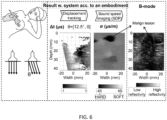
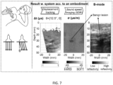
- Fig. 6 and Fig. 7 provide examples of the clinical applicability of embodiments of the present invention to tumor delineation and differentiation.
- In-vivo data were recorded at the University Hospital of Zurich for a female patient showing a cancerous lesion - which biopsy revealed as invasive ductal carcinoma ( Fig. 6 ), and a second female patient showing a benign lesion - confirmed to be a fibroadenoma ( Fig. 7 ).
- Conventional ultrasound B-mode images are provided for both lesions, both appearing as a dark region followed by a shadow region, which do not show a delineation and differentiation of the lesions in terms of gray level contrast.
- Multi-static data A(t, tx, rx) was acquired based on a commercial FDA-approved SonixTouch research ultrasound machine, from Ultrasonix Medical Corporation, Richmond, BC, Canada.
- the process is repeated for all transmitter elements, so that a total of N 2 time traces were recorded in ⁇ 0.1 s (about 100 MB).
- the displacement tracking (motion estimation) algorithm described in Eq T.1 was applied between beamformed images corresponding to increasing ⁇ pairs.
- a texture correlation block of 1x1 mm 2 (52x3 pixels 2 ) was used, with a search range of 0.125 us.
- a one-dimensional correlation search was performed in y , using a zero-normalized cross-correlation (ZNCCC) to find the vertical displacement ⁇ y in metrs at each point (x, y).
- Time measurements ⁇ m with correlation coefficients c yx ⁇ m , n opt ⁇ > 0.5 were discarded from the measurements.
- the "multi-angle anisotropically weighted total variation (MA-AWTV)" with three gradient (-22.5°, 0°, 22.5°) directions was used.
- the path lengths l p,c were calculated with linear interpolation.
- Figure 6 and Figure 7 show speed-of-sound images reconstructed with the SDR method.
- the measurement data ⁇ t shows large empty regions corresponding to the tissue regions no displacement information could be extracted. These were observed for instance in image areas not traversed by the plane wavefront, but also in the low echogenicity region observed around the breast lesions.
- any displacement tracking algorithm may show tracking failures, corresponding to image areas, where speckle information is not sufficient for extracting displacements.
- the presently suggested SDR reconstruction can handle these empty regions, allowing inputting incomplete tracked frames into the reconstruction.
- An FDR requires a complete ⁇ t measurement for all the tissue region.
- the combination of a large part of measurement data missing, together with the noise of the speckle measurements leads to a poor reconstruction, in which the tumorous inclusions cannot be delineated.
- the SDR reconstruction provides a clear delineation of the malignant tumor region, in agreement with the inclusion visible in the B-mode image.
- the sound-speed imaging allows for a sharp delineation of the tumor area where sound-speed changes occur, which is not possible in the B-mode images, due to the shadowing (increased acoustic attenuation) behind the lesions.
- Displacement estimation preferably is used in elastography, where local displacements are observed in response to some external excitation in order to estimate tissue viscoelasticity.
- Displacement tracking preferably is used in order to infer apparent displacements due to differences in speed-of-sound (SoS).
- SoS speed-of-sound
- the image processing and analysis techniques of optical flow and image registration may also be capable of finding displacements. This then allows for standard techniques, such as parametric (B-spline) or non-parametric displacement estimators, as well as using the consistency of displacement across several frames to increase accuracy and resolve ambiguities by removing outliers in displacement estimations.
- standard techniques such as parametric (B-spline) or non-parametric displacement estimators
- the ultrasound transducer may comprise a set of transducer elements each containing one emitter element and one receiver element, or a combined emitter and receiver element.
- the emitter elements of the set and the receiver elements of the set, or the transducer elements respectively are arranged in a straight row.
- the first direction of the gradients of the ultrasound parameters is a direction y orthogonal to a longitudinal extension of the set of emitter elements Tx and the set of receiver elements Rx, or the transducer elements respectively, and the second direction x is orthogonal to the first direction y.
- the emitter elements of the set and the receiver elements of the set, or the transducer elements respectively are arranged in a curved line, and preferably along a convex line.
- Each transducer element, or each emitter element and receiver element has a principal direction referred to as radiation axis along which the transducer element emits ultrasound.
- the first direction y of the gradients of the ultrasound parameters represents an average of the radiation axes of the set of emitter elements Tx and the set of receiver elements Rx, or the set of the transducer elements respectively.
- the second direction x is orthogonal to the first direction y.
- the second direction is defined by a maximum angle ⁇ max with respect to the first direction, which maximum angle ⁇ max is defined by a maximum inclination of the ultrasound beam or non-focused ultrasound wavefront transmitted by the set of emitter elements Tx and received by the set of receiver elements Rx, and a third direction preferably is defined by the negative maximum angle ( ⁇ max ).
- every transducer element may have a defined radiating axis y.
- several transducer elements together can allow angulation of the ultrasound transmission, for instance, by generating plane waves with a defined angle, or by generating a steered ultrasound beam.
- ⁇ max a maximum angle that preferably can be generated is referred to as ⁇ max which preferably is dependent on physical constraints as side lobes, or design decisions to use just a limited set of angles.
- Fig. 4 illustrates a block diagram of a medical ultrasound system according to an embodiment of the present invention, employing two different approaches in generating an ultrasound based tomographic image, and including one or more preferred buildings blocks already addressed in the previous sections.
- only one of the approaches of generating an ultrasound based tomographic image is implemented and is applied in a medical ultrasound system.
- ultrasound signal frames are generated from the tissue to be investigated in block 110, preferably by means of an ultrasound transducer.
- Each frame preferably represents an ultrasound wave received by one or more receiver elements of the transducer in response to an ultrasound wave emitted by one or more of the emitter elements of the transducer.
- Each frame, and hence each measurement preferably is taken from a different plane-wave angle, i.e. by holding the transducer in a different angle relative to the tissue to be investigated, such as is illustrated in Fig. 1 , for example.
- timing of the ultrasound signal frames corresponding to different paths through the tissue / angles of the ultrasound transducer is evaluated. For this purpose, displacement tracking is performed in block 120 for any frames corresponding to different measurement angles, however with a focus on the same location of the tissue.
- local mis-registration between two or more frames is performed in block 125. Based on such mis-registrations, represented e.g. by differences in the measurements in time, a spatial-domain reconstruction is applied in block 130, which effectively leads to a determination of a speed of sound distribution over the discretized tissue region, see block 135. The speed of sound distribution may then be graphically displayed as ultrasound based tomographic image.
- the ultrasound parameter to be determined per discretized cell of the tissue is not speed of sound but attenuation, instead. Accordingly, it is not timing information in the received ultrasound signal frames that is evaluated, but it is the amplitude or power of the ultrasound signal frames received, see block 140. Hence, an amplitude or power comparison is performed for any frames corresponding to different measurement angles, however with a focus on the same location of the tissue.
- local amplitude / power shifts are determined in block 145 for the respective signal frames.
- a spatial domain reconstruction is applied in block 150 providing an attenuation distribution over the discretized tissue region, see block 155. The attenuation distribution may then be graphically displayed as an ultrasound-based tomographic image.
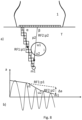
- FIG. 8 illustrates a method and a medical ultrasound system according to an embodiment of the present invention.
- the physical set-up of the medical ultrasound system of FIG. 8a is identical to the set-up shown in FIG. 1 .
- the ultrasound parameter extracted from the measurements is different: While in Fig. 1 , the ultrasound parameter investigated is speed of sound, in FIG. 8 , it is attenuation of the ultrasound wave. Accordingly, if put into context with the embodiment of FIG. 4 , the embodiment of FIG. 1 may represent a system / an approach including the upper branch of the block diagram of FIG. 4 , while the embodiment of FIG. 8 may represent a system including the lower branch of the block diagram of FIG. 4 .
- Fig. 8a again, two sample ultrasound waves are directed towards location m1 in the wave-plane.
- the waves are referred to as RF1 and RF2, wherein wave RF1 takes path p1 inclined by angle ⁇ with respect to the row of the elements of the transducer 1, while wave RF2 takes path p2 inclined by angle ⁇ with respect to the row of elements of the transducer 1.
- wave RF1 takes path p1 inclined by angle ⁇ with respect to the row of the elements of the transducer 1
- wave RF2 takes path p2 inclined by angle ⁇ with respect to the row of elements of the transducer 1.
- path p1 there is no inclusion
- inclusion i is traversed between locations u1 and u2.
- an envelope of the amplitude or power of the corresponding waves is referred to by RF1 and RF2 their travel through the tissue T. It can be derived, that wave RF1 not passing any inclusion is less damped than wave RF2 passing the inclusion i.
- a difference in the envelope of the amplitudes of the waves (such as received at the corresponding receiver elements) is referred to as shift in amplitude or power ⁇ a in FIG. 8b ), comparable to the difference of time of flight values for the embodiment of Fig. 1 . Accordingly, instead of a time difference between the time of flight values of two waves travelling different paths through the tissue resulting in the determination of speed of sound values for the individual cells, such as shown in FIG. 1 , now a difference between the amplitudes / powers of two waves - and more precisely of the two reflected waves as received by the receiver elements - allows for determining attenuation values for the individual cells according to FIG. 8 .
Landscapes
- Engineering & Computer Science (AREA)
- Physics & Mathematics (AREA)
- Radar, Positioning & Navigation (AREA)
- Remote Sensing (AREA)
- Health & Medical Sciences (AREA)
- Life Sciences & Earth Sciences (AREA)
- Computer Networks & Wireless Communication (AREA)
- Acoustics & Sound (AREA)
- General Physics & Mathematics (AREA)
- Radiology & Medical Imaging (AREA)
- Molecular Biology (AREA)
- Pathology (AREA)
- Biophysics (AREA)
- Biomedical Technology (AREA)
- Heart & Thoracic Surgery (AREA)
- Medical Informatics (AREA)
- Nuclear Medicine, Radiotherapy & Molecular Imaging (AREA)
- Surgery (AREA)
- Animal Behavior & Ethology (AREA)
- General Health & Medical Sciences (AREA)
- Public Health (AREA)
- Veterinary Medicine (AREA)
- Computer Vision & Pattern Recognition (AREA)
- Ultra Sonic Daignosis Equipment (AREA)
Claims (28)
- Système médical à ultrasons comprenant- un transducteur à ultrasons (1) pour émettre et recevoir des ultrasons, et- un processeur (51),dans lequel le transducteur à ultrasons (1) est connecté électriquement au processeur (51), etdans lequel le processeur (51) est configuré pour déterminer une image tomographique basée sur les ultrasons au moyen de la vitesse du son et de la reconstruction de l'atténuation acoustique sous réserve des ondes ultrasonores (usr) reçues par le transducteur à ultrasons (1) en réponse aux ondes ultrasonores émises par le transducteur à ultrasons (1) et diffusées et/ou réfléchies par le tissu à examiner.
- Système médical à ultrasons selon la revendication 1,
sans réflecteur artificiel pour réfléchir les ondes ultrasonores émises. - Système médical à ultrasons selon la revendication 1 ou la revendication 2,
dans lequel le transducteur à ultrasons (1) est un appareil à ultrasons portatif (10). - Système médical à ultrasons selon l'une des revendications précédentes,dans lequel le transducteur à ultrasons (1) comprend un ensemble d'éléments émetteurs (Tx) et un ensemble d'éléments récepteurs (Rx),dans lequel le processeur (51) est configuré, pour un ensemble de combinaisons élément émetteur (Tx) - élément récepteur (Rx), pour déclencher l'élément émetteur respectif (Tx) pour émettre une onde ultrasonore (usr),dans lequel le processeur (51) est configuré, pour chacune des combinaisons élément émetteur (Tx) - élément récepteur (Rx) de l'ensemble, pour déterminer une valeur de temps de parcours (tp) ou une amplitude ou une mesure d'amplitude (ap) pour l'onde ultrasonore (usr) se propageant de l'élément émetteur (Tx) à l'élément récepteur (Rx),dans lequel le processeur (51) est configuré pour déterminer des valeurs des paramètres ultrasonores (σ, α) de l'onde ultrasonore (usr) pour les cellules (ci,j) dans un plan (x, y) défini par l'onde ultrasonore émise en fonction des valeurs de temps de parcours (tp) ou des amplitudes ou des mesures d'amplitude (ap), etdans lequel le processeur (51) est configuré pour convertir les valeurs des paramètres ultrasonores (σ, α) en l'image.
- Système médical à ultrasons selon la revendication 4,dans lequel le processeur (51) est configuré pour déterminer les valeurs des paramètres ultrasonores (σ, α) en fonction d'une différence des valeurs de temps de parcours (tp) pour différents trajets de propagation des ondes ultrasonores (p) définis par différentes combinaisons élément émetteur/s (Tx) - élément récepteur/s (Rx) de l'ensemble, eten particulier, dans lequel le paramètre ultrasonore (σ, α) est la vitesse du son (σ).
- Système médical à ultrasons selon la revendication 4 ou la revendication 5,dans lequel le processeur (51) est configuré pour résoudre un système d'équations qui relie un ensemble discret de mesures temporelles aux valeurs de la vitesse du son (σ) dans un nombre discret de cellules (ci,j),en particulier, dans lequel une mesure temporelle de l'ensemble représente une différence des valeurs de temps de parcours (tp) pour différents chemins de propagation d'ondes ultrasonores (p),en particulier, le processeur (51) étant configuré pour déterminer les valeurs de vitesse du son (σ) pour les cellules (ci,j) en résolvant le système d'équations.
- Système médical à ultrasons selon la revendication 5 ou la revendication 6,
dans lequel le processeur (51) est configuré pour calculer les variations de la vitesse du son dans chacune des cellules (ci,j) de l'ensemble à partir de relations discrétisées entre les incréments de vitesse du son dans les cellules individuelles (ci,j) de l'ensemble et les mesures de temps cumulées enregistrées par le transducteur (1), étant donné des trajets de propagation définis (p). - Système médical à ultrasons selon la revendication 6 ou la revendication 7,
dans lequel les mesures de temps sont exprimées par une combinaison linéaire des valeurs de vitesse du son dans le nombre discret de cellules. - Système médical à ultrasons selon l'une des revendications précédentes 5 à 8,dans lequel les trajets de propagation de l'onde ultrasonore (p) de l'ensemble convergent tous vers un point ou une région commune de l'espace insonifié ou le traversent, oudans lequel l'onde ultrasonore a un front d'onde divergent, oudans lequel l'onde ultrasonore a un front d'onde circulaire.
- Système médical à ultrasons selon l'une des revendications précédentes 4 à 9,
dans lequel le processeur (51) est configuré pour déterminer les valeurs des paramètres ultrasonores (σ, α) à partir d'un ensemble de valeurs de paramètres ultrasonores dépendant des gradients des valeurs des paramètres ultrasonores (σ,α) des cellules voisines (ci,j). - Système médical à ultrasons selon l'une des revendications précédentes 4 à 10,
dans lequel le processeur (51) est configuré pour déterminer les valeurs des paramètres ultrasonores (σ, α) parmi un ensemble de valeurs de paramètres ultrasonores dépendant des gradients des valeurs des paramètres ultrasonores des cellules voisines (ci,j) dans au moins deux directions dans le plan (x, y). - Système médical à ultrasons selon la revendication 11,
dans lequel le processeur (51) est configuré pour déterminer les valeurs des paramètres ultrasonores (σ, α) parmi l'ensemble des valeurs des paramètres ultrasonores dépendant des gradients des valeurs des paramètres ultrasonores dans une première direction dans le plan (x, y), et dépendant d'un gradient des valeurs des paramètres ultrasonores dans une deuxième direction dans le plan (x, y) différente de la première direction. - Système médical à ultrasons selon la revendication 12,dans lequel la première direction est une direction (y) orthogonale à une extension longitudinale de l'ensemble d'éléments émetteurs (Tx) et de l'ensemble d'éléments récepteurs (Rx), et dans lequel la deuxième direction (x) est orthogonale à la première direction (y),de préférence, dans lequel les éléments émetteurs de l'ensemble et les éléments récepteurs de l'ensemble sont disposés en ligne droite.
- Système médical à ultrasons selon la revendication 12,dans lequel chaque élément transducteur comprenant un élément émetteur et un élément récepteur a une direction principale appelée axe de rayonnement le long duquel l'élément transducteur émet des ultrasons,dans lequel la première direction représente (y) une moyenne des axes de rayonnement de l'ensemble des éléments émetteurs (Tx) et de l'ensemble des éléments récepteurs (Rx),dans lequel la deuxième direction (x) est une direction (y) orthogonale à une extension longitudinale de l'ensemble d'éléments émetteurs (Tx) et de l'ensemble d'éléments récepteurs (Rx), et dans lequel la deuxième direction (x) est orthogonale à la première direction (y),de préférence, dans lequel les éléments émetteurs de l'ensemble et les éléments récepteurs de l'ensemble sont disposés selon une ligne courbe, et de préférence selon une ligne convexe.
- Système médical à ultrasons selon l'une des revendications précédentes 12 ou 14,
dans lequel le processeur (51) est configuré pour déterminer les valeurs des paramètres ultrasonores (σ, α) à partir de l'ensemble des valeurs des paramètres ultrasonores en fonction en outre des gradients des valeurs des paramètres ultrasonores dans une troisième direction dans le plan (x, y), de préférence différente de la première et de la deuxième direction. - Système médical à ultrasons selon la revendication 15,dans laquelle la deuxième direction est définie par un angle maximal (φmax) par rapport à la première direction, qui est défini par une inclinaison maximale du faisceau ultrasonore ou du front d'onde ultrasonore non focalisé transmis par l'ensemble d'éléments émetteurs (Tx) et reçu par l'ensemble d'éléments récepteurs (Rx),dans laquelle la troisième direction est définie par l'angle maximal négatif (φmax).
- Système médical à ultrasons selon l'une des revendications précédentes 3 à 16,
dans lequel le processeur (51) est configuré pour déterminer les valeurs de paramètres ultrasonores (σ, α) parmi un ensemble de valeurs de paramètres ultrasonores dépendant des gradients pondérés des valeurs de paramètres ultrasonores des cellules voisines (ci,j) dans au moins deux directions dans le plan (x, y). - Système médical à ultrasons selon la revendication 17,
dans lequel le processeur (51) est configuré pour appliquer le même poids (k) à tous les gradients de la même direction, et différents poids (k, 1-k) par direction. - Système médical à ultrasons selon l'une des revendications précédentes 12 à 18,
dans lequel le processeur (51) est configuré pour appliquer un premier poids (k) à tous les gradients de la première direction, et un second poids (1-k) à tous les gradients de la seconde direction, le premier poids (k) étant supérieur au second poids (1-k). - Système médical à ultrasons selon l'une des revendications précédentes 12 à 19,
dans lequel le processeur (51) est configuré pour appliquer un premier poids à tous les gradients de la première direction, un deuxième poids à tous les gradients de la deuxième direction et un troisième poids à tous les gradients de la troisième direction. - Système médical à ultrasons selon l'une des revendications précédentes,
dans lequel le processeur (51) est configuré pour déterminer la valeur de la vitesse du son (σ) pour chaque cellule (ci,j) soit en tant que valeur unique, soit en fonction de la fréquence, soit en fonction de toute perturbation appliquée au tissu. - Système médical à ultrasons selon l'une des revendications précédentes,dans lequel le paramètre ultrasonore (σ, α) est l'atténuation acoustique (α),dans lequel le processeur (51) est configuré pour déterminer une valeur d'atténuation acoustique (α) pour chaque cellule (ci,j), de préférence sous forme de valeur unique, ou en fonction de la fréquence, ou en fonction de toute perturbation appliquée au tissu.
- Système médical à ultrasons selon l'une des revendications précédentes 4 à 22,
dans lequel les valeurs des paramètres ultrasonores (σ, α) sont identifiées à plusieurs fréquences ultrasonores émises, ce qui permet de reconstruire la dépendance en fréquence de ces paramètres. - Système médical à ultrasons selon l'une des revendications précédentes,
dans lequel le processeur (51) est configuré pour déterminer une distance entre le transducteur (1) et une structure (m) dans le tissu en fonction d'une valeur de temps de parcours (tp) en réponse au déclenchement d'une onde ultrasonore au niveau du transducteur (1). - Système médical à ultrasons selon l'une des revendications précédentes,dans lequel l'unité de traitement est configurée pour appliquer une régularisation par variation totale dans le calcul des images ultrasonores tomographiques, eten particulier dans lequel, dans la régularisation par variation totale, l'équation à résoudre suit la forme argmin_σ {∥Δt - Lσ∥_p + λ∥D σ∥_q} ou toute combinaison de telles formes, où Δt est un vecteur de quantités mesurées, σ le vecteur inconnu à reconstruire, L une matrice calculée géométriquement en tenant compte de la géométrie du montage, D une matrice de gradient et λ une constante, p et q étant les ordres des normes respectives, eten particulier dans lequel l'équation est résolue par optimisation convexe,en particulier dans laquelle p = 1 et q = 1.
- Système médical à ultrasons selon l'une des revendications précédentes 4 à 25,comprenant le fonctionnement du transducteur à ultrasons par l'émission d'une onde ultrasonore par un seul élément émetteur et les éléments récepteurs recevant l'onde ultrasonore émise et diffusée et/ou réfléchie,et de préférence en faisant fonctionner le transducteur à ultrasons de telle sorte que chaque élément émetteur émette ensuite une onde ultrasonore et que les éléments récepteurs reçoivent l'onde ultrasonore émise et diffusée et/ou réfléchie.
- Procédé de détermination d'une image tomographique basée sur les ultrasons, comprenantemmètre d'ultrasons par un transducteur à ultrasons (1) en direction du tissu à examiner, et la réception d'ultrasons diffusés et/ou réfléchis par le tissu à examiner par le transducteur à ultrasons (1), etdéterminer l'image tomographique basée sur les ultrasons en fonction des ondes ultrasonores (usr) reçues par le transducteur à ultrasons (1) par un processeur (51).
- Procédé de détermination d'une image tomographique à base d'ultrasons selon la revendication 27, comprenantcollectionner une pluralité de signaux ultrasonores pour permettre l'accès à un ensemble de points dans un domaine imagé à partir de trajectoires passant par différentes régions du domaine,déterminer les erreurs d'enregistrement locales entre cette pluralité de signaux ultrasonores, etutiliser une reconstruction dans le domaine spatial basée sur les erreurs d'enregistrement calculées dans un espace de problème discrétisé, de préférence dans le tissu discrétisé à étudier, etde préférence, déterminer l'image tomographique basée sur les ultrasons à partir de la reconstruction du domaine spatial pour l'espace de problème discrétisé.
Applications Claiming Priority (2)
| Application Number | Priority Date | Filing Date | Title |
|---|---|---|---|
| EP17158183 | 2017-02-27 | ||
| PCT/EP2018/054666 WO2018154109A1 (fr) | 2017-02-27 | 2018-02-26 | Système et procédé de reconstruction de vitesse et d'atténuation d'imagerie ultrasonore |
Publications (2)
| Publication Number | Publication Date |
|---|---|
| EP3577491A1 EP3577491A1 (fr) | 2019-12-11 |
| EP3577491B1 true EP3577491B1 (fr) | 2023-10-04 |
Family
ID=58185429
Family Applications (1)
| Application Number | Title | Priority Date | Filing Date |
|---|---|---|---|
| EP18709958.5A Active EP3577491B1 (fr) | 2017-02-27 | 2018-02-26 | Système et procédé de reconstruction de vitesse et d'atténuation d'imagerie ultrasonore |
Country Status (3)
| Country | Link |
|---|---|
| US (1) | US20200008779A1 (fr) |
| EP (1) | EP3577491B1 (fr) |
| WO (1) | WO2018154109A1 (fr) |
Families Citing this family (23)
| Publication number | Priority date | Publication date | Assignee | Title |
|---|---|---|---|---|
| US12102473B2 (en) | 2008-06-06 | 2024-10-01 | Ulthera, Inc. | Systems for ultrasound treatment |
| CN204017181U (zh) | 2013-03-08 | 2014-12-17 | 奥赛拉公司 | 美学成像与处理系统、多焦点处理系统和执行美容过程的系统 |
| US11423312B2 (en) * | 2018-05-14 | 2022-08-23 | Samsung Electronics Co., Ltd | Method and apparatus for universal pruning and compression of deep convolutional neural networks under joint sparsity constraints |
| US11284858B1 (en) * | 2018-07-02 | 2022-03-29 | Triad National Security, Llc | Systems and methods for plane-wave and fan-beam ultrasound-waveform tomography |
| JP2022513577A (ja) | 2018-11-30 | 2022-02-09 | ウルセラ インコーポレイテッド | 超音波処置の効能を増強させるためのシステムおよび方法 |
| CA3137928A1 (fr) | 2019-07-15 | 2021-01-21 | Ulthera, Inc. | Systemes et procedes de mesure de l'elasticite par imagerie d'ondes de cisaillement multi-foyer a ultrasons dans de multiples dimensions |
| GB2587604B (en) | 2019-09-20 | 2022-07-13 | Norwegian Univ Sci & Tech Ntnu | Ultrasound cardiac processing |
| CN111466951B (zh) * | 2020-04-15 | 2023-04-07 | 深圳开立生物医疗科技股份有限公司 | 超声衰减图像的生成方法、装置、超声设备及存储介质 |
| US12178637B2 (en) * | 2020-09-18 | 2024-12-31 | Bk Medical Aps | Image fusion-based tracking without a tracking sensor |
| US11559285B2 (en) | 2021-02-17 | 2023-01-24 | Vortex Imaging Ltd. | Reflection ultrasound tomographic imaging using full-waveform inversion |
| DE102021105020A1 (de) * | 2021-03-02 | 2022-09-08 | Carl Zeiss Microscopy Gmbh | Mikroskopiesystem und Verfahren zum Verarbeiten eines Mikroskopbildes |
| CN114519770B (zh) * | 2022-01-07 | 2025-07-29 | 南京航空航天大学 | 一种腰骶丛神经分割及三维可视化方法 |
| KR20240151187A (ko) * | 2022-02-18 | 2024-10-17 | 인쎄름 (엥스띠뛰 나씨오날 드 라 쌍떼 에 드 라 흐쉐르슈 메디깔) | 혈관 활동을 미세한 규모에서 동적으로 영상화하기 위한 방법 및 장치 |
| CN115736986B (zh) * | 2022-11-09 | 2024-07-23 | 哈尔滨工业大学 | 基于l1范数的源编码全波形反演超声层析成像方法及设备 |
| CN120417841A (zh) * | 2022-12-20 | 2025-08-01 | 奥赛拉公司 | 用于高分辨率超声成像伪影减少的系统和方法 |
| US12533110B2 (en) * | 2023-01-10 | 2026-01-27 | Echosens | Elastography device and method |
| CN116223510B (zh) * | 2023-02-14 | 2026-03-27 | 复旦大学 | 一种基于散射光飞行时间差的表面细微缺陷重建方法 |
| CN117173042B (zh) * | 2023-08-23 | 2024-05-31 | 长春理工大学 | 一种基于单向变分的遥感数据条纹噪声去除方法、装置及介质 |
| CN117589889B (zh) * | 2024-01-19 | 2024-04-02 | 江苏省特种设备安全监督检验研究院 | 一种基于有限元模型的超声相控阵微裂纹检测方法及系统 |
| CN118000786B (zh) * | 2024-04-10 | 2024-07-19 | 之江实验室 | 一种基于解剖学先验的超声层析成像方法和系统 |
| CN118296858B (zh) * | 2024-06-05 | 2024-10-18 | 汕头市超声仪器研究所股份有限公司 | 一种全聚焦成像声场快速仿真方法 |
| CN118746834B (zh) * | 2024-07-09 | 2025-12-30 | 电子科技大学 | 基于改进全变分的前视扫描雷达超分辨成像方法 |
| CN121118480B (zh) * | 2025-11-17 | 2026-03-24 | 合肥综合性国家科学中心人工智能研究院(安徽省人工智能实验室) | 一种超声断层成像换能器设计方法、系统、介质及产品 |
Family Cites Families (5)
| Publication number | Priority date | Publication date | Assignee | Title |
|---|---|---|---|---|
| US6475150B2 (en) * | 2000-12-01 | 2002-11-05 | The Regents Of The University Of California | System and method for ultrasonic tomography |
| US7785259B2 (en) * | 2003-10-03 | 2010-08-31 | Mayo Foundation For Medical Education And Research | Detection of motion in vibro-acoustography |
| EP2568883B1 (fr) * | 2010-05-07 | 2017-11-15 | Esaote S.p.A. | Procédé et appareil d'acquisition d'images ultrasonores |
| US8663113B2 (en) * | 2011-08-11 | 2014-03-04 | Delphinus Medical Technologies, Inc. | Method for imaging a volume of tissue |
| US10271819B2 (en) | 2013-12-16 | 2019-04-30 | Universitat Bern | Computed ultrasound tomography in echo mode (CUTE) for imaging speed of sound using pulse-echo sonography |
-
2018
- 2018-02-26 WO PCT/EP2018/054666 patent/WO2018154109A1/fr not_active Ceased
- 2018-02-26 US US16/488,872 patent/US20200008779A1/en not_active Abandoned
- 2018-02-26 EP EP18709958.5A patent/EP3577491B1/fr active Active
Also Published As
| Publication number | Publication date |
|---|---|
| US20200008779A1 (en) | 2020-01-09 |
| WO2018154109A1 (fr) | 2018-08-30 |
| EP3577491A1 (fr) | 2019-12-11 |
Similar Documents
| Publication | Publication Date | Title |
|---|---|---|
| EP3577491B1 (fr) | Système et procédé de reconstruction de vitesse et d'atténuation d'imagerie ultrasonore | |
| Renaud et al. | In vivo ultrasound imaging of the bone cortex | |
| Sanabria et al. | Spatial domain reconstruction for imaging speed-of-sound with pulse-echo ultrasound: simulation and in vivo study | |
| US9084559B2 (en) | Imaging method, displacement measurement method and apparatus | |
| JP7634444B2 (ja) | 媒体の超音波特性評価用の方法とシステム | |
| US10271819B2 (en) | Computed ultrasound tomography in echo mode (CUTE) for imaging speed of sound using pulse-echo sonography | |
| CN111819467B (zh) | 波传播和散射参数的估计方法和仪器 | |
| US12153131B2 (en) | Method and system for ultrasonic characterization of a medium | |
| US20110172538A1 (en) | Displacement measurement method and apparatus, and ultrasonic diagnostic apparatus | |
| Sanabria et al. | Speed-of-sound imaging based on reflector delineation | |
| KR20220036863A (ko) | 매질의 초음파 특성화 방법 및 시스템 | |
| JP7654066B2 (ja) | 媒体の超音波特性評価用の方法及びシステム | |
| Sanabria et al. | Hand-held sound-speed imaging based on ultrasound reflector delineation | |
| Hooi et al. | Analysis of tissue changes, measurement system effects, and motion artifacts in echo decorrelation imaging | |
| US20250208098A1 (en) | Method of characterizing a target object in a medium | |
| Nguyen et al. | Estimation of backscatter coefficients using an in situ calibration source | |
| Lasaygues et al. | Contrast resolution enhancement of Ultrasonic Computed Tomography using a wavelet-based method–Preliminary results in bone imaging | |
| Martiartu et al. | Towards attenuation imaging with computed ultrasound tomography in echo mode (CUTE) | |
| Sugioka et al. | Investigation on synthetic aperture imaging using focused transmit beams for cardiac ultrasonography | |
| CN113424073A (zh) | 材料非线性体积弹性的超声估算 | |
| Feigin et al. | Computing speed-of-sound from ultrasound: user-agnostic recovery and a new benchmark | |
| Korta Martiartu et al. | Pulse-echo ultrasound attenuation tomography | |
| Hajian et al. | Accurate 3-D profile extraction of skull bone using an ultrasound matrix array | |
| Sumi | Utilization of an ultrasound beam steering angle for measurements of tissue displacement vector and lateral displacement | |
| Li et al. | Multiplicative frequency and angular speckle reduction in ultrasound imaging |
Legal Events
| Date | Code | Title | Description |
|---|---|---|---|
| STAA | Information on the status of an ep patent application or granted ep patent |
Free format text: STATUS: UNKNOWN |
|
| STAA | Information on the status of an ep patent application or granted ep patent |
Free format text: STATUS: THE INTERNATIONAL PUBLICATION HAS BEEN MADE |
|
| PUAI | Public reference made under article 153(3) epc to a published international application that has entered the european phase |
Free format text: ORIGINAL CODE: 0009012 |
|
| STAA | Information on the status of an ep patent application or granted ep patent |
Free format text: STATUS: REQUEST FOR EXAMINATION WAS MADE |
|
| 17P | Request for examination filed |
Effective date: 20190819 |
|
| AK | Designated contracting states |
Kind code of ref document: A1 Designated state(s): AL AT BE BG CH CY CZ DE DK EE ES FI FR GB GR HR HU IE IS IT LI LT LU LV MC MK MT NL NO PL PT RO RS SE SI SK SM TR |
|
| AX | Request for extension of the european patent |
Extension state: BA ME |
|
| DAV | Request for validation of the european patent (deleted) | ||
| DAX | Request for extension of the european patent (deleted) | ||
| GRAP | Despatch of communication of intention to grant a patent |
Free format text: ORIGINAL CODE: EPIDOSNIGR1 |
|
| STAA | Information on the status of an ep patent application or granted ep patent |
Free format text: STATUS: GRANT OF PATENT IS INTENDED |
|
| RIC1 | Information provided on ipc code assigned before grant |
Ipc: G01S 7/52 20060101ALI20230330BHEP Ipc: A61B 8/00 20060101ALI20230330BHEP Ipc: A61B 8/08 20060101ALI20230330BHEP Ipc: G01S 15/89 20060101AFI20230330BHEP |
|
| INTG | Intention to grant announced |
Effective date: 20230425 |
|
| GRAS | Grant fee paid |
Free format text: ORIGINAL CODE: EPIDOSNIGR3 |
|
| GRAA | (expected) grant |
Free format text: ORIGINAL CODE: 0009210 |
|
| STAA | Information on the status of an ep patent application or granted ep patent |
Free format text: STATUS: THE PATENT HAS BEEN GRANTED |
|
| AK | Designated contracting states |
Kind code of ref document: B1 Designated state(s): AL AT BE BG CH CY CZ DE DK EE ES FI FR GB GR HR HU IE IS IT LI LT LU LV MC MK MT NL NO PL PT RO RS SE SI SK SM TR |
|
| REG | Reference to a national code |
Ref country code: GB Ref legal event code: FG4D |
|
| REG | Reference to a national code |
Ref country code: CH Ref legal event code: EP |
|
| REG | Reference to a national code |
Ref country code: DE Ref legal event code: R096 Ref document number: 602018058611 Country of ref document: DE |
|
| REG | Reference to a national code |
Ref country code: IE Ref legal event code: FG4D |
|
| REG | Reference to a national code |
Ref country code: LT Ref legal event code: MG9D |
|
| REG | Reference to a national code |
Ref country code: NL Ref legal event code: MP Effective date: 20231004 |
|
| REG | Reference to a national code |
Ref country code: AT Ref legal event code: MK05 Ref document number: 1618288 Country of ref document: AT Kind code of ref document: T Effective date: 20231004 |
|
| PG25 | Lapsed in a contracting state [announced via postgrant information from national office to epo] |
Ref country code: NL Free format text: LAPSE BECAUSE OF FAILURE TO SUBMIT A TRANSLATION OF THE DESCRIPTION OR TO PAY THE FEE WITHIN THE PRESCRIBED TIME-LIMIT Effective date: 20231004 |
|
| PG25 | Lapsed in a contracting state [announced via postgrant information from national office to epo] |
Ref country code: GR Free format text: LAPSE BECAUSE OF FAILURE TO SUBMIT A TRANSLATION OF THE DESCRIPTION OR TO PAY THE FEE WITHIN THE PRESCRIBED TIME-LIMIT Effective date: 20240105 |
|
| PG25 | Lapsed in a contracting state [announced via postgrant information from national office to epo] |
Ref country code: IS Free format text: LAPSE BECAUSE OF FAILURE TO SUBMIT A TRANSLATION OF THE DESCRIPTION OR TO PAY THE FEE WITHIN THE PRESCRIBED TIME-LIMIT Effective date: 20240204 |
|
| PG25 | Lapsed in a contracting state [announced via postgrant information from national office to epo] |
Ref country code: LT Free format text: LAPSE BECAUSE OF FAILURE TO SUBMIT A TRANSLATION OF THE DESCRIPTION OR TO PAY THE FEE WITHIN THE PRESCRIBED TIME-LIMIT Effective date: 20231004 |
|
| PG25 | Lapsed in a contracting state [announced via postgrant information from national office to epo] |
Ref country code: AT Free format text: LAPSE BECAUSE OF FAILURE TO SUBMIT A TRANSLATION OF THE DESCRIPTION OR TO PAY THE FEE WITHIN THE PRESCRIBED TIME-LIMIT Effective date: 20231004 |
|
| PG25 | Lapsed in a contracting state [announced via postgrant information from national office to epo] |
Ref country code: ES Free format text: LAPSE BECAUSE OF FAILURE TO SUBMIT A TRANSLATION OF THE DESCRIPTION OR TO PAY THE FEE WITHIN THE PRESCRIBED TIME-LIMIT Effective date: 20231004 |
|
| PG25 | Lapsed in a contracting state [announced via postgrant information from national office to epo] |
Ref country code: LT Free format text: LAPSE BECAUSE OF FAILURE TO SUBMIT A TRANSLATION OF THE DESCRIPTION OR TO PAY THE FEE WITHIN THE PRESCRIBED TIME-LIMIT Effective date: 20231004 Ref country code: IS Free format text: LAPSE BECAUSE OF FAILURE TO SUBMIT A TRANSLATION OF THE DESCRIPTION OR TO PAY THE FEE WITHIN THE PRESCRIBED TIME-LIMIT Effective date: 20240204 Ref country code: GR Free format text: LAPSE BECAUSE OF FAILURE TO SUBMIT A TRANSLATION OF THE DESCRIPTION OR TO PAY THE FEE WITHIN THE PRESCRIBED TIME-LIMIT Effective date: 20240105 Ref country code: ES Free format text: LAPSE BECAUSE OF FAILURE TO SUBMIT A TRANSLATION OF THE DESCRIPTION OR TO PAY THE FEE WITHIN THE PRESCRIBED TIME-LIMIT Effective date: 20231004 Ref country code: BG Free format text: LAPSE BECAUSE OF FAILURE TO SUBMIT A TRANSLATION OF THE DESCRIPTION OR TO PAY THE FEE WITHIN THE PRESCRIBED TIME-LIMIT Effective date: 20240104 Ref country code: AT Free format text: LAPSE BECAUSE OF FAILURE TO SUBMIT A TRANSLATION OF THE DESCRIPTION OR TO PAY THE FEE WITHIN THE PRESCRIBED TIME-LIMIT Effective date: 20231004 Ref country code: PT Free format text: LAPSE BECAUSE OF FAILURE TO SUBMIT A TRANSLATION OF THE DESCRIPTION OR TO PAY THE FEE WITHIN THE PRESCRIBED TIME-LIMIT Effective date: 20240205 |
|
| PG25 | Lapsed in a contracting state [announced via postgrant information from national office to epo] |
Ref country code: SE Free format text: LAPSE BECAUSE OF FAILURE TO SUBMIT A TRANSLATION OF THE DESCRIPTION OR TO PAY THE FEE WITHIN THE PRESCRIBED TIME-LIMIT Effective date: 20231004 Ref country code: RS Free format text: LAPSE BECAUSE OF FAILURE TO SUBMIT A TRANSLATION OF THE DESCRIPTION OR TO PAY THE FEE WITHIN THE PRESCRIBED TIME-LIMIT Effective date: 20231004 Ref country code: PL Free format text: LAPSE BECAUSE OF FAILURE TO SUBMIT A TRANSLATION OF THE DESCRIPTION OR TO PAY THE FEE WITHIN THE PRESCRIBED TIME-LIMIT Effective date: 20231004 Ref country code: NO Free format text: LAPSE BECAUSE OF FAILURE TO SUBMIT A TRANSLATION OF THE DESCRIPTION OR TO PAY THE FEE WITHIN THE PRESCRIBED TIME-LIMIT Effective date: 20240104 Ref country code: LV Free format text: LAPSE BECAUSE OF FAILURE TO SUBMIT A TRANSLATION OF THE DESCRIPTION OR TO PAY THE FEE WITHIN THE PRESCRIBED TIME-LIMIT Effective date: 20231004 Ref country code: HR Free format text: LAPSE BECAUSE OF FAILURE TO SUBMIT A TRANSLATION OF THE DESCRIPTION OR TO PAY THE FEE WITHIN THE PRESCRIBED TIME-LIMIT Effective date: 20231004 |
|
| REG | Reference to a national code |
Ref country code: DE Ref legal event code: R097 Ref document number: 602018058611 Country of ref document: DE |
|
| PG25 | Lapsed in a contracting state [announced via postgrant information from national office to epo] |
Ref country code: DK Free format text: LAPSE BECAUSE OF FAILURE TO SUBMIT A TRANSLATION OF THE DESCRIPTION OR TO PAY THE FEE WITHIN THE PRESCRIBED TIME-LIMIT Effective date: 20231004 |
|
| PG25 | Lapsed in a contracting state [announced via postgrant information from national office to epo] |
Ref country code: CZ Free format text: LAPSE BECAUSE OF FAILURE TO SUBMIT A TRANSLATION OF THE DESCRIPTION OR TO PAY THE FEE WITHIN THE PRESCRIBED TIME-LIMIT Effective date: 20231004 |
|
| PG25 | Lapsed in a contracting state [announced via postgrant information from national office to epo] |
Ref country code: SK Free format text: LAPSE BECAUSE OF FAILURE TO SUBMIT A TRANSLATION OF THE DESCRIPTION OR TO PAY THE FEE WITHIN THE PRESCRIBED TIME-LIMIT Effective date: 20231004 |
|
| PG25 | Lapsed in a contracting state [announced via postgrant information from national office to epo] |
Ref country code: SM Free format text: LAPSE BECAUSE OF FAILURE TO SUBMIT A TRANSLATION OF THE DESCRIPTION OR TO PAY THE FEE WITHIN THE PRESCRIBED TIME-LIMIT Effective date: 20231004 Ref country code: SK Free format text: LAPSE BECAUSE OF FAILURE TO SUBMIT A TRANSLATION OF THE DESCRIPTION OR TO PAY THE FEE WITHIN THE PRESCRIBED TIME-LIMIT Effective date: 20231004 Ref country code: RO Free format text: LAPSE BECAUSE OF FAILURE TO SUBMIT A TRANSLATION OF THE DESCRIPTION OR TO PAY THE FEE WITHIN THE PRESCRIBED TIME-LIMIT Effective date: 20231004 Ref country code: IT Free format text: LAPSE BECAUSE OF FAILURE TO SUBMIT A TRANSLATION OF THE DESCRIPTION OR TO PAY THE FEE WITHIN THE PRESCRIBED TIME-LIMIT Effective date: 20231004 Ref country code: EE Free format text: LAPSE BECAUSE OF FAILURE TO SUBMIT A TRANSLATION OF THE DESCRIPTION OR TO PAY THE FEE WITHIN THE PRESCRIBED TIME-LIMIT Effective date: 20231004 Ref country code: DK Free format text: LAPSE BECAUSE OF FAILURE TO SUBMIT A TRANSLATION OF THE DESCRIPTION OR TO PAY THE FEE WITHIN THE PRESCRIBED TIME-LIMIT Effective date: 20231004 Ref country code: CZ Free format text: LAPSE BECAUSE OF FAILURE TO SUBMIT A TRANSLATION OF THE DESCRIPTION OR TO PAY THE FEE WITHIN THE PRESCRIBED TIME-LIMIT Effective date: 20231004 |
|
| PLBE | No opposition filed within time limit |
Free format text: ORIGINAL CODE: 0009261 |
|
| STAA | Information on the status of an ep patent application or granted ep patent |
Free format text: STATUS: NO OPPOSITION FILED WITHIN TIME LIMIT |
|
| 26N | No opposition filed |
Effective date: 20240705 |
|
| PG25 | Lapsed in a contracting state [announced via postgrant information from national office to epo] |
Ref country code: MC Free format text: LAPSE BECAUSE OF FAILURE TO SUBMIT A TRANSLATION OF THE DESCRIPTION OR TO PAY THE FEE WITHIN THE PRESCRIBED TIME-LIMIT Effective date: 20231004 |
|
| PG25 | Lapsed in a contracting state [announced via postgrant information from national office to epo] |
Ref country code: LU Free format text: LAPSE BECAUSE OF NON-PAYMENT OF DUE FEES Effective date: 20240226 |
|
| PG25 | Lapsed in a contracting state [announced via postgrant information from national office to epo] |
Ref country code: SI Free format text: LAPSE BECAUSE OF FAILURE TO SUBMIT A TRANSLATION OF THE DESCRIPTION OR TO PAY THE FEE WITHIN THE PRESCRIBED TIME-LIMIT Effective date: 20231004 |
|
| PG25 | Lapsed in a contracting state [announced via postgrant information from national office to epo] |
Ref country code: SI Free format text: LAPSE BECAUSE OF FAILURE TO SUBMIT A TRANSLATION OF THE DESCRIPTION OR TO PAY THE FEE WITHIN THE PRESCRIBED TIME-LIMIT Effective date: 20231004 Ref country code: LU Free format text: LAPSE BECAUSE OF NON-PAYMENT OF DUE FEES Effective date: 20240226 |
|
| REG | Reference to a national code |
Ref country code: BE Ref legal event code: MM Effective date: 20240229 |
|
| PG25 | Lapsed in a contracting state [announced via postgrant information from national office to epo] |
Ref country code: BE Free format text: LAPSE BECAUSE OF NON-PAYMENT OF DUE FEES Effective date: 20240229 |
|
| PG25 | Lapsed in a contracting state [announced via postgrant information from national office to epo] |
Ref country code: IE Free format text: LAPSE BECAUSE OF NON-PAYMENT OF DUE FEES Effective date: 20240226 |
|
| PG25 | Lapsed in a contracting state [announced via postgrant information from national office to epo] |
Ref country code: IE Free format text: LAPSE BECAUSE OF NON-PAYMENT OF DUE FEES Effective date: 20240226 Ref country code: BE Free format text: LAPSE BECAUSE OF NON-PAYMENT OF DUE FEES Effective date: 20240229 |
|
| PG25 | Lapsed in a contracting state [announced via postgrant information from national office to epo] |
Ref country code: CY Free format text: LAPSE BECAUSE OF FAILURE TO SUBMIT A TRANSLATION OF THE DESCRIPTION OR TO PAY THE FEE WITHIN THE PRESCRIBED TIME-LIMIT; INVALID AB INITIO Effective date: 20180226 |
|
| PG25 | Lapsed in a contracting state [announced via postgrant information from national office to epo] |
Ref country code: HU Free format text: LAPSE BECAUSE OF FAILURE TO SUBMIT A TRANSLATION OF THE DESCRIPTION OR TO PAY THE FEE WITHIN THE PRESCRIBED TIME-LIMIT; INVALID AB INITIO Effective date: 20180226 |
|
| PG25 | Lapsed in a contracting state [announced via postgrant information from national office to epo] |
Ref country code: FI Free format text: LAPSE BECAUSE OF FAILURE TO SUBMIT A TRANSLATION OF THE DESCRIPTION OR TO PAY THE FEE WITHIN THE PRESCRIBED TIME-LIMIT Effective date: 20231004 |
|
| PG25 | Lapsed in a contracting state [announced via postgrant information from national office to epo] |
Ref country code: TR Free format text: LAPSE BECAUSE OF FAILURE TO SUBMIT A TRANSLATION OF THE DESCRIPTION OR TO PAY THE FEE WITHIN THE PRESCRIBED TIME-LIMIT Effective date: 20231004 |
|
| REG | Reference to a national code |
Ref country code: CH Ref legal event code: U11 Free format text: ST27 STATUS EVENT CODE: U-0-0-U10-U11 (AS PROVIDED BY THE NATIONAL OFFICE) Effective date: 20260301 |
|
| PGFP | Annual fee paid to national office [announced via postgrant information from national office to epo] |
Ref country code: GB Payment date: 20260219 Year of fee payment: 9 |
|
| PGFP | Annual fee paid to national office [announced via postgrant information from national office to epo] |
Ref country code: DE Payment date: 20260217 Year of fee payment: 9 |
|
| PGFP | Annual fee paid to national office [announced via postgrant information from national office to epo] |
Ref country code: FR Payment date: 20260223 Year of fee payment: 9 |
|
| PGFP | Annual fee paid to national office [announced via postgrant information from national office to epo] |
Ref country code: CH Payment date: 20260301 Year of fee payment: 9 |