EP3577776B1 - Transmetteur et procédé de transmission de symboles sur un canal de communication sans fil - Google Patents
Transmetteur et procédé de transmission de symboles sur un canal de communication sans fil Download PDFInfo
- Publication number
- EP3577776B1 EP3577776B1 EP17751856.0A EP17751856A EP3577776B1 EP 3577776 B1 EP3577776 B1 EP 3577776B1 EP 17751856 A EP17751856 A EP 17751856A EP 3577776 B1 EP3577776 B1 EP 3577776B1
- Authority
- EP
- European Patent Office
- Prior art keywords
- receiver
- symbol
- transmitter
- transmission
- aods
- Prior art date
- Legal status (The legal status is an assumption and is not a legal conclusion. Google has not performed a legal analysis and makes no representation as to the accuracy of the status listed.)
- Active
Links
Images



Classifications
-
- H—ELECTRICITY
- H04—ELECTRIC COMMUNICATION TECHNIQUE
- H04B—TRANSMISSION
- H04B7/00—Radio transmission systems, i.e. using radiation field
- H04B7/02—Diversity systems; Multi-antenna system, i.e. transmission or reception using multiple antennas
- H04B7/04—Diversity systems; Multi-antenna system, i.e. transmission or reception using multiple antennas using two or more spaced independent antennas
- H04B7/06—Diversity systems; Multi-antenna system, i.e. transmission or reception using multiple antennas using two or more spaced independent antennas at the transmitting station
- H04B7/0613—Diversity systems; Multi-antenna system, i.e. transmission or reception using multiple antennas using two or more spaced independent antennas at the transmitting station using simultaneous transmission
- H04B7/0615—Diversity systems; Multi-antenna system, i.e. transmission or reception using multiple antennas using two or more spaced independent antennas at the transmitting station using simultaneous transmission of weighted versions of same signal
- H04B7/0617—Diversity systems; Multi-antenna system, i.e. transmission or reception using multiple antennas using two or more spaced independent antennas at the transmitting station using simultaneous transmission of weighted versions of same signal for beam forming
-
- H—ELECTRICITY
- H04—ELECTRIC COMMUNICATION TECHNIQUE
- H04B—TRANSMISSION
- H04B14/00—Transmission systems not characterised by the medium used for transmission
- H04B14/002—Transmission systems not characterised by the medium used for transmission characterised by the use of a carrier modulation
- H04B14/006—Angle modulation
-
- H—ELECTRICITY
- H04—ELECTRIC COMMUNICATION TECHNIQUE
- H04B—TRANSMISSION
- H04B7/00—Radio transmission systems, i.e. using radiation field
- H04B7/02—Diversity systems; Multi-antenna system, i.e. transmission or reception using multiple antennas
-
- H—ELECTRICITY
- H04—ELECTRIC COMMUNICATION TECHNIQUE
- H04B—TRANSMISSION
- H04B7/00—Radio transmission systems, i.e. using radiation field
- H04B7/02—Diversity systems; Multi-antenna system, i.e. transmission or reception using multiple antennas
- H04B7/04—Diversity systems; Multi-antenna system, i.e. transmission or reception using multiple antennas using two or more spaced independent antennas
- H04B7/06—Diversity systems; Multi-antenna system, i.e. transmission or reception using multiple antennas using two or more spaced independent antennas at the transmitting station
- H04B7/0613—Diversity systems; Multi-antenna system, i.e. transmission or reception using multiple antennas using two or more spaced independent antennas at the transmitting station using simultaneous transmission
- H04B7/0615—Diversity systems; Multi-antenna system, i.e. transmission or reception using multiple antennas using two or more spaced independent antennas at the transmitting station using simultaneous transmission of weighted versions of same signal
- H04B7/0619—Diversity systems; Multi-antenna system, i.e. transmission or reception using multiple antennas using two or more spaced independent antennas at the transmitting station using simultaneous transmission of weighted versions of same signal using feedback from receiving side
-
- H—ELECTRICITY
- H04—ELECTRIC COMMUNICATION TECHNIQUE
- H04B—TRANSMISSION
- H04B7/00—Radio transmission systems, i.e. using radiation field
- H04B7/02—Diversity systems; Multi-antenna system, i.e. transmission or reception using multiple antennas
- H04B7/04—Diversity systems; Multi-antenna system, i.e. transmission or reception using multiple antennas using two or more spaced independent antennas
- H04B7/06—Diversity systems; Multi-antenna system, i.e. transmission or reception using multiple antennas using two or more spaced independent antennas at the transmitting station
- H04B7/0613—Diversity systems; Multi-antenna system, i.e. transmission or reception using multiple antennas using two or more spaced independent antennas at the transmitting station using simultaneous transmission
- H04B7/0615—Diversity systems; Multi-antenna system, i.e. transmission or reception using multiple antennas using two or more spaced independent antennas at the transmitting station using simultaneous transmission of weighted versions of same signal
- H04B7/0619—Diversity systems; Multi-antenna system, i.e. transmission or reception using multiple antennas using two or more spaced independent antennas at the transmitting station using simultaneous transmission of weighted versions of same signal using feedback from receiving side
- H04B7/0621—Feedback content
- H04B7/0626—Channel coefficients, e.g. channel state information [CSI]
-
- H—ELECTRICITY
- H04—ELECTRIC COMMUNICATION TECHNIQUE
- H04B—TRANSMISSION
- H04B7/00—Radio transmission systems, i.e. using radiation field
- H04B7/02—Diversity systems; Multi-antenna system, i.e. transmission or reception using multiple antennas
- H04B7/04—Diversity systems; Multi-antenna system, i.e. transmission or reception using multiple antennas using two or more spaced independent antennas
- H04B7/06—Diversity systems; Multi-antenna system, i.e. transmission or reception using multiple antennas using two or more spaced independent antennas at the transmitting station
- H04B7/0686—Hybrid systems, i.e. switching and simultaneous transmission
- H04B7/0691—Hybrid systems, i.e. switching and simultaneous transmission using subgroups of transmit antennas
-
- H—ELECTRICITY
- H04—ELECTRIC COMMUNICATION TECHNIQUE
- H04B—TRANSMISSION
- H04B7/00—Radio transmission systems, i.e. using radiation field
- H04B7/02—Diversity systems; Multi-antenna system, i.e. transmission or reception using multiple antennas
- H04B7/10—Polarisation diversity; Directional diversity
-
- H—ELECTRICITY
- H04—ELECTRIC COMMUNICATION TECHNIQUE
- H04L—TRANSMISSION OF DIGITAL INFORMATION, e.g. TELEGRAPHIC COMMUNICATION
- H04L5/00—Arrangements affording multiple use of the transmission path
- H04L5/003—Arrangements for allocating sub-channels of the transmission path
- H04L5/0048—Allocation of pilot signals, i.e. of signals known to the receiver
Definitions
- the present invention relates to a transmitter, a receiver adapted to communicate with the transmitter, a method for transmitting symbols over a wireless communication channel, and a non-transitory computer readable storage medium embodied thereon a program executable by a processor for performing a method.
- Millimeter Waves are radio waves with wavelength in the range of 1 millimeter (mm)-10 mm, which corresponds to a radio frequency of 30 GigaHertz (GHz)-300 GHz. Per the definition by the International Telecommunications Union (ITU), these frequencies are also referred to as the Extremely High Frequency (EHF) band.
- ITU International Telecommunications Union
- EHF Extremely High Frequency
- the mmWaves exhibit unique propagation characteristics. For example, compared with lower frequency radio waves, mmWaves suffer higher propagation loss, have a poorer ability to penetrate objects, such as buildings, walls, foliage, and are more susceptible to atmosphere absorption, deflection and diffraction due to particles (e.g., rain drops) in the air. On the other hand, due to the smaller wavelengths of the mmWaves, more antennas can be packed in a relatively small area, thereby allowing for the implementation of a high-gain antenna in small form factor.
- the mm Waves have been less utilized than the lower frequency radio waves.
- a vast amount of spectrum is available in the mm Wave band.
- the frequencies around 60 GHz which are typically referred to as the 60 GHz band, are available as unlicensed spectrum in most countries. This is one of the reasons that the mmWave spectrum has been proposed for cellular communications in the fifth generation (5G).
- spatial multiplexing is a transmission technique in MIMO communication used to transmit independent and separately encoded data signals from each of the multiple antennas. Therefore, the space dimension is reused, or multiplexed, more than one time.
- the spatial multiplexing is impractical for the mm Waves transmission.
- Spatial modulation is a transmission technique that uses an index of transmit antenna as an additional source of information to improve the overall spectral efficiency, see, e.g., WO2011104502 .
- index of transmit antenna as an additional source of information to improve the overall spectral efficiency
- US 2016/134024 A1 describes a data transmitting apparatus in a wireless communication system which determines a beam angle according to an input bit signal sequence and forms a pencil beam in a direction of the beam angle that is determined using a plurality of transmitting antennas.
- US 2015/124738 A1 describes a method for performing channel estimation, the method comprising: identifying a set of preferred base station (BS) receive beams for each of a plurality of BS antenna sub-arrays (SAs) based on periodic pilot transmissions from a user equipment (UE) transmitted using predefined UE transmit beams; transmitting a request for the UE to transmit pilot signals for the set of preferred BS receive beams; receiving the pilot signals using the set of preferred BS receive beams; performing channel estimation and determining data transmission parameters based on the received pilot signals, the data transmission parameters including at least one receive beam at each UE antenna SA to be used for data reception; and transmitting, to the UE, information for identifying the at least one receive beam at each UE antenna SA to be used for data reception.
- BS base station
- SAs BS antenna sub-arrays
- the invention is set out in the appended set of claims.
- the mm Waves exhibit unique propagation characteristics. For example, compared with lower frequency radio waves, mmWaves suffer higher propagation loss. However, since the wavelength is small, it is possible to pack more antenna elements in the same aperture to form a beamforming that can achieve high gains and efficient isolation to other users. On one hand, this directional beamforming makes the mm Wave spectrum attractive for wireless communication. On the other hand, the beamforming makes impractical the spatial modulation method that uses an index of transmit antenna as an additional source of information.
- a pattern of AoA can be associated with the specific beam that causes this pattern. Hence, upon this pattern is received in a future, the AoD of the specific beam that causes this pattern can be readily identified.
- spatial beamforming modulation may be used for increasing a transmission rate.
- the spatial beamforming modulation uses an index of AoD of a transmission beam as an additional source of information.
- Spatial beamforming modulation is suitable for mm Wave communication.
- the mmWave channel has several specific properties for propagation of mm Waves.
- the mm Wave channel is sparse in the number of arrivals of mmWaves impinging upon the receiver array.
- the propagated mm Waves are spread in angular domain and can potentially exhibit a specific power profile.
- Such properties of the mmWave transmission increase the uniqueness of different patterns of AoAs governed by different AoDs.
- Pilot transmission beams enable the receiver to estimate a pattern of AoAs for each index of AoD.
- the transmitter can transmit the pilot beams to the receiver in a predetermined order and/or can include an index of AoD at each pilot transmission.
- Such a pilot transmission enables the receiver to perform the channel estimation.
- the receiver can estimate a pattern of AoA for each AoD to produce a mapping between indices of different AoDs and values of the symbols.
- the transmitter receives such a mapping from the receiver.
- the receiver can produce such a mapping for all available AoDs.
- the receiver can include a fewer number of AoDs in the mapping.
- the transmitter select different modulation schemes based on a number of AoDs specified in the mapping.
- a transmitter including a plurality of antennas for beamforming with different angles of departure (AoD); an information interface to receive a sequence of symbols including a first symbol and a second symbol; and a modulator to cause the plurality of antennas to form a transmission beam with an AoD selected according to a value of the first symbol and modulated according to a value of the second symbol, wherein the modulator is further configured to cause the plurality of antennas to perform pilot transmission with transmission beams having different AoDs to enable at least one receiver to estimate a pattern of arrival impinging upon antennas of the receiver for different transmission beams; wherein the transmitter further comprises a memory configured to store a mapping between different AoDs and values of the symbols, wherein the mapping is received from the at least one receiver in response to performing the pilot transmission; and wherein the modulator is configured to vary a type of modulation based on a number of AoDs specified in the mapping.
- AoD angles of departure
- Another embodiment discloses a method for transmitting symbols over a wireless communication channel.
- the method includes receiving a sequence of symbols including a first symbol and a second symbol; selecting an angle of departure (AoD) based on a value of the first symbol; modulating a radio frequency (RF) signal according to a value of the second symbol; and performing a beamforming to transmit the RF signal as a transmission beam with the selected AoD.
- AoD angle of departure
- RF radio frequency
- the method further comprises: performing a pilot transmission with a receiver with transmission beams having different AoDs to enable the receiver to estimate a pattern of arrival impinging upon antennas of the receiver for different transmission beams; receiving, in response to the pilot transmission, a mapping between indices of different AoDs and values of the symbols, such that the selecting is performed based on the mapping; and varying the modulating based on a number of AoDs specified in the mapping.
- Yet another embodiment discloses a non-transitory computer readable storage medium embodied thereon a program executable by a processor for performing a method.
- the method includes receiving a sequence of symbols including a first symbol and a second symbol; selecting an angle of departure (AoD) based on a value of the first symbol; modulating a radio frequency (RF) signal according to a value of the second symbol; and performing a beamforming to transmit the RF signal as a transmission beam with the selected AoD.
- AoD angle of departure
- RF radio frequency
- the method further comprises: performing a pilot transmission with a receiver with transmission beams having different AoDs to enable the receiver to estimate a pattern of arrival impinging upon antennas of the receiver for different transmission beams; receiving, in response to the pilot transmission, a mapping between indices of different AoDs and values of the symbols, such that the selecting is performed based on the mapping; and varying the modulating based on a number of AoDs specified in the mapping.
- FIG. 1A shows a block diagram of a transmitter 100 for transmitting symbols over a wireless communication channel according to some embodiments.
- the transmitter 100 includes a plurality of antennas 101 for beamforming with different angles of departure (AoD) 101a, 102a, 103a, and 104a.
- the beamforming can form one transmission beam, e.g., the beam 102a, at each point of time.
- the AoD can include one or combination of an azimuth angle and an altitude angle of the transmitted beam.
- the AoD and/or an index of the AoD is selected to convey information.
- different AoDs are selected based on different values of information to be transmitted. This principle is referred herein as spatial beamforming modulation.
- the spatial beamforming modulation uses an AoD of a transmission beam as an additional source of information.
- the transmitter 100 includes an information interface 140 to receive a sequence of symbols including a first symbol 145 and a second symbol 147.
- the information interface 140 can include a memory storing the sequence of symbols, a network interface for receiving the sequence of symbols, and/or a device for converting any type of information into the set of symbols.
- the information interface can include a microphone for converting speech into the sequence of symbols.
- the transmitter 100 includes a modulator 110 enabling the spatial beamforming modulation.
- the modulator 110 causes the plurality of antennas 101 to form a transmission beam with an AoD selected 120 according to a value of the first symbol 145 and modulated 130 according to a value of the second symbol 130. In such a manner, only the value of the second symbol is transmitted to a receiver. However, because the value of the second symbol is transmitted over the transmission beam with the AoD selected based on the value of the first symbol, the receiver is able to decode the values of both the first and the second symbols.
- the spatial beamforming modulation increases the transmission rate by taking advantage of the multiple antennas of the transmitter and is suitable for mmWave transmission.
- the transmitter has an access to a mapping between different AoDs and values of the symbols. This mapping is agreed with the receiver and allows the transmitter to effectively select the AoD based on the value of the first symbol.
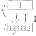
- Figure 1B shows an exemplar structure 180 used by the modulator 110 to select the AoD according to some embodiments.
- the structure 180 includes a memory 160 to store a mapping 170 between different AoDs 172 and values of the symbols 174.
- the structure also includes a processor 150 to select the AoD based on the value of the symbol.
- the mapping is received from the receiver and/or updated based on channel estimation between the receiver and the transmitter.
- the channel estimation is performed by the receiver in response to a pilot transmission performed by the transmitter.
- the receiver determines the mapping 170 based on the channel estimation and transmits the mapping 170 back to the transmitter.
- a pattern of AoA can be associated with the specific beam that causes this pattern. Hence, when this pattern is received in a future, the AoD of the specific beam that causes this pattern can be readily identified.
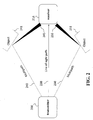
- Figure 2 shows schematic illustrating principles of propagation of the mmWaves in the mmWave channel employed by some examples.
- a signal sent from the transmitter 208 reaches the receiver 214 via few paths 230, 240 and 250. Since the wavelengths of the electro-magnetic waves in the mmWave system are likely comparable with the roughness of the object 241, 251 surfaces that bounce off the waves, the arrivals at the receiver are likely spread in the angular domain 245, 255. This feature has been confirmed in a number of reported measurement campaigns and is part of the existing standard IEEE 802.11ad for indoor mm Wave communications at 60GHz. Some examples exploit this observation to devise an enhanced channel estimation method.
- Some examples are based on recognition that the mm Waves propagating in the mmWave channel are spread upon arrivals and departures, such that the mm Waves are detected as clusters of the mm Waves at the receiver forming a pattern of AoAs.
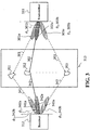
- Figure 3 shows a schematic of transmissions from a transmitter 311 to a receiver 312 through a set of scattering clusters 351, 352, 353 according to an example.
- the scattering clusters 351, 352, 353 can include walls of the buildings in the environment 313 connecting the transmitter and the receiver. In some situations, there are no direct paths connecting the transmitter to receiver due to line of sight signal (LOS) blocking by the scattering clusters. In another example, direct path with higher power is also used for communications as an additional path.
- LOS line of sight signal
- the transmitter forms directional beams, 301a, 302a, 303a through directions, 301, 302, 303 redirected from the scattering clusters 351, 352, 353.
- AoDs 301b, 302b, 303b selected based on some values of transmitted symbols.
- the received signal through the receiving directions, 341, 342, 343 can be identified by steering the corresponding receiving beams 341a, 342a, 343a with corresponding angle of arrival (AoA), 341b, 342b, 343b.
- the receiver detects the AoA of the path with the strongest gain.
- the receiver can associate the beam 302a with the AoD 302 to correspond to the AoA 342b.
- the receiver can perform the channel estimation to determine a pattern of AoAs of multiple signals resulting from the transmission of a single beam such as the beam 302a.
- the information bits can be modulated not only on the transmitted symbol, but also on the transmission directions to encode additional bits.
- N s scattering clusters for spatial scattering modulation (SSM), and M-ary constellation for symbol modulation.
- SSM spatial scattering modulation
- M-ary constellation for symbol modulation.
- the first log 2 ( N s ) bits are used to decide which direction to transmit, and the next log 2 ( M ) bits are used to decide which point in the constellation to use.
- the maximum likelihood detection can be used to decode the symbol as well as the transmission direction.
- additional bits are encoded in the direction, i.e., the first log 2 ( N s ) bits.
- the modulator causes the plurality of antennas to perform pilot transmission with transmission beams having different AoDs to enable at least one receiver to estimate a pattern of arrival impinging upon antennas of the receiver for different transmission beams.
- the pilot transmissions can be performed in the order of indexes of AoDs.
- each pilot transmission beam includes an index of the AoD.
- compressive channel estimation or beam steering may be used to estimate AoD and AoA at the transmitter and receiver.
- ⁇ is the wavelength of the propagation.
- the numbers of antenna elements at the transmitter and receiver are, respectively, given by N t and N r .
- N t and N r are large, which is valid in our architecture, we have asymptotically a t ( ⁇ l ) H a t ( ⁇ k ) ⁇ 0, ⁇ l ⁇ k, and a r ( ⁇ l ) H a r ( ⁇ k ) ⁇ 0, ⁇ l ⁇ k.
- AoA and AoD are nearly orthogonal each other.
- the antenna elements are aligned in a free-form position not in uniform linear manner to improve the spherical spatial resolution.
- the mm Waves propagating in the mm Wave channel are spread upon arrivals and departures, such that the mm Waves are detected as clusters of the mm Waves at the receiver. Due to the clustering, the statistics of the paths of mmWaves include statistics on locations of the clusters in a space of propagation of the mmWaves, and the statistics on the spread of mmWaves include statistics on a spread density of the cluster.
- Figure 4 shows a schematic of various metrics of statistics in the space of propagation of the mmWaves according to some examples.
- the space of propagation of the mm Waves can be represented as a Carterisan product of the set of possible angles of the AoDs of the mm Waves and angles of the directions of AoAs of the mm Waves.
- one domain of the space of propagation in mm Wave channel is a virtual angular domain, pictorially shown in Figure 4 in the case where, without loss of generality, both transmitter and receiver employ vertical line arrays of antennas.
- channel between each transmitter antenna element and each receiver antenna element is a flat fading channel, and thus represented via a single complex gain.
- All complex gain coefficients, corresponding to all possible pairs of transmitter and receiver antenna elements are formatted into a channel matrix H, such that (i,j) entry in H represents a channel gain between the i th antenna element on the receiver side and the j th antenna element on the transmitter side.
- H s is the virtual angular domain representation of the channel.
- the virtual angular domain can be pictorially represented as a two-dimensional grid 400, representing AoA 401 and AoD 402 along the axis.
- the virtual angular representation of a mm Wave channel shown in Figure 4 indicates that there are two paths 410 and 420 between transmitter and receiver where each transmitted and received beam has some angular spread.
- the channel estimation problem may be formulated as a problem of sparse representation of the received channel sensing signals in a redundant dictionary.
- the redundant dictionary includes atoms which depend on the transmitter and receiver manifold vectors.
- the channel can be estimated by employing one of a variety of sparse recovery methods, such as orthogonal matching pursuit (OMP) method.
- OMP orthogonal matching pursuit
- Figure 5 shows a block diagram of a sparse recovery method of the channel estimation performed by the receiver according to an example.
- the signal vector 540 can be obtained after pre-processing the test symbol received on a receiver array.
- the signal vector is represented as a product of a wide dictionary matrix 530 and a sparse channel vector 550, modified with noise 560.
- This representation can be obtained by transmitting a test symbol, e.g., a symbol with a known value one, after precoding the test symbol using a certain number of precoding vectors 510 and processing the received signal with a certain number of mixing vectors 520.
- non-zero elements of the channel vector include the coefficients of the channel state information, wherein values of the signal vector and the dictionary matrix are known from the test symbol and transmitter and receiver manifold vectors.
- the dictionary matrix and the signal vector may be determined from the precoding and mixing vectors, as well as transmitter and receiver manifold vectors, using various algebraic operations which encompass sparse recovery formulation 500.
- the precoding vectors are of size equal to the number of transmitter antenna elements and, in general, may contain random or pseudo-random complex exponentials.
- the mixing vectors are of size equal to the number of employed antenna elements and may contain random or pseudo-random complex exponentials.
- the signal vector and dictionary matrix are computed from the precoding and mixing vectors, as well as from the transmitter and receiver manifold vectors.
- the channel estimation problem then boils down to finding a sparse representation of the signal vector 540 in the redundant dictionary 530, where the coefficients of the sparse representation constitute unknown channel vector 550.
- the estimated channel vector is then mapped back to the representation in the virtual angular domain H s , which, in turn, is mapped to channel matrix H, using (1).
- Figure 6 shows exemplar architecture of a transmitter 600 according to an example.
- the transmitter includes one or several radio frequency (RF) chains 603 to convert the modulated value of the second symbol into a RF signal of a predetermined frequency and a set of phase shifters 602 to provide a controllable phase shift of transmission of the RF signal via the plurality of antennas that forms the transmission beam having the selected AoD.
- RF radio frequency
- the modulated symbols are converted to the RF signal via digital-to-analog converter (DAC), 605, and frequency converter, 604.
- DAC digital-to-analog converter
- the transmitter uses only one RF chain 603.
- the transmitter can be equipped with multiple RF chains and a set of phase shifter arrays.
- Digital beamforming requires each antenna element connected to its own RF chain, so that one main concern with the digital beamforming is the power consumption and hardware cost.
- an analog beamforming and hybrid beamforming require only a limited number of RF chains, which connect an antenna array through a phase shifter array.
- the transmitter also includes a set of power amplifiers 610 for amplifying the RF signal.
- the power amplifiers PAs
- the power amplifiers amplify the RF signal with the constant rate.
- the power amplifiers amplify the RF signal as a function of a gain of a channel formed by the transmission beam with the selected AoD.
- phase shifter array 602 that includes N T phase shifters and PAs.
- the outputs of the PAs are then passing through to an antenna array 101 that includes N T antenna elements.
- the phase shifter array 602 can also control the amplitude. This additional degree of freedom to change not only phase but also amplitude can provide even finer spatial resolution and higher antenna gains.
- Figure 7 shows exemplar architecture of the receiver 700 in communication with the transmitter of Figure 6 according to an example.
- the receiver has more available hardware resources than a transmitter.
- the receiver 700 can include one or up to N RF chains 701 and 711 each of which connects to its phase shifter array 702 and 712 that include N r phase shifters each.
- the phase shifter at the receiver can also control amplitude of the received signals 750.
- the signal from each antenna passes through the low noise amplifier (LNA) 725, and then the output signal from the LNA is split into N signals.
- LNA low noise amplifier
- signals 703a and 703b are fed into the first phase shifter in each phase shifter array702 and 712.
- Outputs from the phase shifter array 702 and 712 are fed into its connecting RF chains 701 and 711.
- ADC analog to digital converter
- the signal passes through the beamformer 720 that estimates the AoA of the received transmission beam.
- the final decoded information data 735 are obtained from the decoder 730 that decodes the second symbol modulated in the transmission beam and to decode the first symbol based on the AoA. Due to the use of an antenna array, the receiver can form a highly directional beam with a very narrow beam width. Also, due to full use of hybrid analog-digital structure and multiple RF chains, any combiners can be formed in the receiver.
- Figure 8 shows a schematic of the communication via spatial beamforming modulation exploiting three-dimensional scattering map with azimuth and altitude angles according to an example.
- a transmitter 810 exploits scattering objects placed in three-dimensional geometry 813b by using spherical directions 890, which are specified by not only azimuth angle but also altitude angle.
- This additional degree of freedom for beamforming control can further decrease interference to undesired directions. For example, even if there are two distinct objects at the same azimuth angle, the transmitter or the receiver may still be able to use two scattering objects independently by using altitude angles.
- Figure 9 shows a block diagram of exemplar implementation of a transmitter using spatial beamforming modulation according to an example.
- the sequence of symbols received from the information interface 140 is decomposed by a switch 950 into at least two sequences.
- the first sequence is passed to a beamforming direction or AoD mapper 910 and the other sequence of symbols is passed to modulation mapper 920.
- AoD mapper 910 Because there are additional degrees of freedom in the direction mapping, a part of input sequence is modulated on the available number of directions to increase the spectral efficiency. For example, four AoDs are selected based on their gains,
- 2 due to four RF chains at the receiver.
- the example first reshapes the data for QPSK modulation to information symbols.
- the example groups every log 2 ( N s ) + log 2 ( M ) bits, that is, (2+2) bits into one group, which can be possible by switch 950 as [ b 1 b 2 ] [ b 3 b 4 ] 1 0 1 0 1 0 0 0 1 0 1 0 0 1 0 1 0 1 0 1 0 1 0 1 0 1 0 1 0 1 0 1 0 1 0 1 0 1 0 1 0 1 0 1 0 1 0 1 0 1 0 1 0 1 0 1 0 1 0 1 0 1 0 1 0 1 0 1 0 1 0 1 0 1 0 1 0 1 0 1 0 1 0 1 0 1 0 1 0 1 0 1 0 1 0 1 0 1 0 1 0 1 0 1 0 1 0 1 0 1 0 1 0
- one azimuth AoD angle is determined as: [0 0] : a t ( ⁇ 1 ) , [0 1] : a t ( ⁇ 2 ), [1 0] : a t ( ⁇ 3 ), [11] : a t ( ⁇ 4 ) so that a precoding direction p ⁇ ⁇ a t ( ⁇ 1 ) , a t ( ⁇ 2 ), a t ( ⁇ 3 ) , a t ( ⁇ 4 ) ⁇ is generated by the direction mapper 910.
- next two bits [ b 3 b 4 ] is selected one of the symbols 0 0 : 1 + j 2 , 0 1 : 1 ⁇ j 2 , 1 0 : ⁇ 1 + j 2 , 1 1 : ⁇ 1 ⁇ j 2
- the modulation mapper 920 uses an information symbol mapping s ⁇ 1 + j 2 1 ⁇ j 2 ⁇ 1 + j 2 ⁇ 1 ⁇ j 2 .
- the following symbols are generated with accompanying directional angles.
- phase shifter array 602 [ b 1 b 2 ] [ b 3 b 4 ] p s ⁇ 1 0 10 a t ( ⁇ 3 ) ⁇ 1 + j 2 ⁇ 3 1 0 00 a t ( ⁇ 3 ) 1 + j 2 ⁇ 3 1 0 10 a t ( ⁇ 3 ) ⁇ 1 + j 2 ⁇ 3 01 01 a t ( ⁇ 2 ) 1 ⁇ j 2 ⁇ 2
- the receiver can infer them from the direction of transmission that represented by p at any time instance and save, e.g., two additional bits for transmissions.
- the phase shifter array 602 can be controlled to select only one directional beam 901a, 902a, 903a, or ... 904a. At each time, additional modulated symbol s is transmitted on the selected beam.
- the transmissions are accomplished as follows:
- log 2 M bits are used to determine which constellation point chosen, whereas log 2 N s bits are used to determine which scattering cluster will be chosen for communications.
- E the transmission power
- n the noise at the receiver.
- the received signal y , 750 becomes
- the receiver combines the received signal via phase shifters.
- the maximum ratio combining (MRC) may be used as the optimal combiner. This makes the receiver beam point to the scattering cluster that corresponds to the transmitted direction. Since N s ⁇ N, where N s denotes the number of selected AoD, N s transmission directions are possible to be used and one direction is selected by the transmitter, the receiver needs to detect an unknown direction used by the transmitter.
- k ⁇ and ⁇ can be detected, so that eventually transmitted information bits [ b ⁇ 1 , b ⁇ 2 ] and [ b ⁇ 3 , b ⁇ 4 ] can be inferred from k ⁇ and ⁇ , respectively.
- the above maximum-likelihood detection can be relaxed by various low-complexity methods such as minimum mean-square error and sphere decoding.
- FIG 10 shows a schematic of an adaptive transmission scheme used by some embodiments.
- the adaptive transmission scheme 901 is based on recognition that when the channel gains vary for different AoDs, the spatial beamforming for strongly fading channels can be suboptimal.
- BER bit error rate
- Examples of different types of modulations include a full spatial beamforming modulation (FSBM) 910, a partial spatial beamforming modulation (PSBM) 920, and maximum spatial beamforming modulation (MSBM) 930.
- FSBM full spatial beamforming modulation
- PSBM partial spatial beamforming modulation
- MSBM maximum spatial beamforming modulation
- the FSBM is used for four AoDs that can add additional two bits in the transmission
- the PSBM is used with two AoDs to add one additional bit per transmitted symbol
- MSBM is used with all available AoDs.
- different types of the modulation can be selected based on a number of AoDs specified in the mapping by the receiver as a result of channel estimation.
- the number of AoDs to use for modulation can be scaled to any arbitrary integer numbers, which are also a variable to adapt in accordance to the instantaneous channel state information.
- the symbol constellation and AoDs are jointly assigned to minimize BER.
- the bits and path assignments are determined to maximize the data throughput.
- This example can solve the issue that the BER performance for different bits allocated to spatial domain and constellation domain can be significantly different.
- the ATS uses throughput calculation.
- the throughput is calculated from block error rate for each bit.
- the throughput is calculated by general mutual information, which is obtained by soft-decision likelihood histogram of the demodulator output.
- the above-described embodiments of the present invention can be implemented in any of numerous ways.
- the embodiments may be implemented using hardware, software or a combination thereof.
- the software code can be executed on any suitable processor or collection of processors, whether provided in a single computer or distributed among multiple computers.
- processors may be implemented as integrated circuits, with one or more processors in an integrated circuit component.
- a processor may be implemented using circuitry in any suitable format.
- embodiments of the invention may be embodied as a method, of which an example has been provided.
- the acts performed as part of the method may be ordered in any suitable way. Accordingly, embodiments may be constructed in which acts are performed in an order different than illustrated, which may include performing some acts simultaneously, even though shown as sequential acts in illustrative embodiments.
Landscapes
- Engineering & Computer Science (AREA)
- Signal Processing (AREA)
- Computer Networks & Wireless Communication (AREA)
- Radio Transmission System (AREA)
Claims (10)
- Émetteur (100, 208, 311, 600, 810), comprenant :une pluralité d'antennes (101) configurées pour la formation de faisceaux avec différents angles de départ ;une interface d'informations (140) configurée pour recevoir une séquence de symboles comprenant un premier symbole et un second symbole ; etun modulateur (110) configuré pour amener la pluralité d'antennes (101) à former un faisceau de transmission avec un angle de départ choisi en fonction d'une valeur du premier symbole et modulé en fonction d'une valeur du second symbole ;caractérisé en ce que le modulateur (110) est en outre configuré pour amener la pluralité d'antennes (101) à effectuer une transmission pilote avec des faisceaux de transmission ayant différents angles de départ pour permettre à au moins un récepteur d'estimer un motif d'arrivée incident sur des antennes du récepteur pour différents faisceaux de transmission ;en ce que l'émetteur (100, 208, 311, 600, 810) comprend en outre une mémoire (160) configurée pour stocker un mappage (170) entre différents angles de départ et des valeurs des symboles, dans lequel le mappage (170) est reçu à partir du au moins un récepteur en réponse à la réalisation de la transmission pilote ; eten ce que le modulateur (110) est configuré pour faire varier un type de modulation sur la base d'un certain nombre d'angles de départ spécifiés dans le mappage (170).
- Émetteur de la revendication 1, dans lequel au moins plusieurs angles de départ comprennent des angles d'azimut et des angles d'altitude, dans lequel le modulateur (110) est configuré pour sélectionner un angle d'azimut et un angle d'altitude de l'angle de départ sur la base de la valeur du premier symbole.
- Émetteur de la revendication 1, comprenant en outre :une chaîne radiofréquence, RF, (603) configurée pour convertir la valeur modulée du second symbole en un signal RF de fréquence prédéterminée ; etun ensemble de déphaseurs (602) configurés pour appliquer un déphasage contrôlable à la transmission du signal RF via la pluralité d'antennes qui forment le faisceau de transmission possédant l'angle de départ choisi.
- Émetteur de la revendication 1, dans lequel une fréquence de chaque faisceau de transmission se situe dans un spectre d'ondes millimétriques.
- Récepteur (214, 312, 700) permettant de communiquer avec l'émetteur de la revendication 1, dans lequel le récepteur comprend :un ensemble d'antennes (704) configurées pour recevoir le faisceau de transmission transmis par l'émetteur en fonction de l'angle de départ choisi ;un processeur (720) configuré pour estimer un angle d'arrivée du faisceau de transmission reçu ; etun décodeur (730) configuré pour décoder le second symbole modulé dans le faisceau de transmission et décoder le premier symbole sur la base de l'angle d'arrivée ;caractérisé en ce que l'ensemble d'antennes (704) est en outre configuré pour recevoir des faisceaux de transmission pilotes transmis par un canal à ondes millimétriques, en ce que le processeur (720) est en outre configuré pour déterminer des informations d'état de canal du canal à ondes millimétriques en appliquant une inférence bayésienne sur chaque faisceau de transmission pilote selon un modèle probabiliste du canal à ondes millimétriques comprenant des statistiques sur les trajets et la distribution des ondes millimétriques se propageant dans le canal à ondes millimétriques et pour déterminer, à l'aide des informations d'état de canal, un mappage (170) entre différents angles de départ et des valeurs des symboles, et en ce que le récepteur (214, 312, 700) comporte en outre un émetteur-récepteur configuré pour transmettre le mappage (170) à l'émetteur, dans lequel le mappage (170) spécifie un certain nombre d'angles de départ.
- Procédé de transmission de symboles par un canal de communication sans fil, comprenant :la réception d'une séquence de symboles comportant un premier symbole et un second symbole ;le choix d'un angle de départ sur la base d'une valeur du premier symbole ;la modulation d'un signal RF en fonction d'une valeur du second symbole ; etl'exécution d'une opération de formation de faisceau pour transmettre le signal RF sous forme de faisceau de transmission avec l'angle de départ choisi ;caractérisé en ce que le procédé comprend en outre :l'exécution d'une opération de transmission pilote avec un récepteur avec des faisceaux de transmission ayant différents angles de départ pour permettre au récepteur d'estimer un motif d'arrivée incident sur des antennes du récepteur pour différents faisceaux de transmission ;la réception, en réponse à la transmission pilote, d'un mappage (170) entre des indices de différents angles de départ et des valeurs des symboles, de sorte que le choix s'effectue sur la base du mappage (170) ; etla variation de la modulation sur la base d'un certain nombre d'angles de départ spécifiés dans le mappage (170).
- Procédé de la revendication 6, dans lequel l'angle de départ comprend un angle d'azimut et un angle d'altitude choisis sur la base de la valeur du premier symbole.
- Procédé de la revendication 6, le procédé utilisant un processeur couplé avec une mémoire stockant un mappage entre des indices de différents angles de départ et des valeurs des symboles, dans lequel le processeur est couplé avec des instructions stockées de mise en œuvre du procédé, et dans lequel les instructions, lorsqu'exécutées par le processeur, mettant en œuvre au moins plusieurs étapes du procédé.
- Support de stockage lisible par ordinateur non transitoire comportant un programme exécutable par un processeur pour mettre en œuvre un procédé, le procédé comprenant :la réception d'une séquence de symboles comprenant un premier symbole et un second symbole ;le choix d'un angle de départ sur la base d'une valeur du premier symbole ;la modulation d'un signal RF en fonction d'une valeur du second symbole ; etl'exécution d'une opération de formation de faisceau pour transmettre le signal RF sous forme de faisceau de transmission avec l'angle de départ choisi ;caractérisé en ce que le procédé comprend en outre :l'exécution d'une opération de transmission pilote avec un récepteur avec des faisceaux de transmission ayant différents angles de départ pour permettre au récepteur d'estimer un motif d'arrivée incident sur des antennes du récepteur pour différents faisceaux de transmission ;la réception, en réponse à la transmission pilote, d'un mappage (170) entre des indices de différents angles de départ et des valeurs des symboles, de sorte que le choix s'effectue sur la base du mappage (170) ; etla variation de la modulation sur la base d'un certain nombre d'angles de départ spécifiés dans le mappage.
- Support de stockage de la revendication 9, dans lequel une fréquence de chaque faisceau de transmission se situe dans un spectre d'ondes millimétriques.
Applications Claiming Priority (2)
| Application Number | Priority Date | Filing Date | Title |
|---|---|---|---|
| US15/424,952 US9948377B1 (en) | 2017-02-06 | 2017-02-06 | System and method for spatial beamforming modulation |
| PCT/JP2017/026171 WO2018142646A1 (fr) | 2017-02-06 | 2017-07-12 | Émetteur et procédé permettant de transmettre des symboles sur un canal de communication sans fil |
Publications (2)
| Publication Number | Publication Date |
|---|---|
| EP3577776A1 EP3577776A1 (fr) | 2019-12-11 |
| EP3577776B1 true EP3577776B1 (fr) | 2021-08-25 |
Family
ID=59593136
Family Applications (1)
| Application Number | Title | Priority Date | Filing Date |
|---|---|---|---|
| EP17751856.0A Active EP3577776B1 (fr) | 2017-02-06 | 2017-07-12 | Transmetteur et procédé de transmission de symboles sur un canal de communication sans fil |
Country Status (5)
| Country | Link |
|---|---|
| US (1) | US9948377B1 (fr) |
| EP (1) | EP3577776B1 (fr) |
| JP (1) | JP2019537297A (fr) |
| CN (1) | CN110235382B (fr) |
| WO (1) | WO2018142646A1 (fr) |
Cited By (1)
| Publication number | Priority date | Publication date | Assignee | Title |
|---|---|---|---|---|
| WO2023196700A1 (fr) * | 2022-04-05 | 2023-10-12 | Qualcomm Incorporated | Sélection de faisceau à l'aide de livres de codes de formation de faisceau sur-échantillonnés et d'estimations de canal |
Families Citing this family (27)
| Publication number | Priority date | Publication date | Assignee | Title |
|---|---|---|---|---|
| FI4002724T3 (fi) | 2015-12-13 | 2025-09-30 | Gxc Llc | Häiriönpoistomenetelmiä ja -laite |
| US10257746B2 (en) * | 2016-07-16 | 2019-04-09 | GenXComm, Inc. | Interference cancellation methods and apparatus |
| US10382230B2 (en) * | 2017-03-31 | 2019-08-13 | Mitsubishi Electric Research Laboratories, Inc. | System and method for channel estimation in mmWave communications exploiting joint AoD-AoA angular spread |
| US10295647B1 (en) * | 2018-03-13 | 2019-05-21 | Cypress Semiconductor Corporation | Asset location using direction finding features |
| WO2019182987A1 (fr) * | 2018-03-19 | 2019-09-26 | Idac Holdings, Inc. | Procédé de multiplexage de liaison montante non orthogonal de types d'informations hétérogènes |
| CN110545129B (zh) * | 2018-05-29 | 2021-01-29 | 华为技术有限公司 | 波束传输方法、装置及系统 |
| US10708090B1 (en) * | 2018-12-27 | 2020-07-07 | Industrial Technology Research Institute | Millimeter wave channel estimation method |
| US11539394B2 (en) | 2019-10-29 | 2022-12-27 | GenXComm, Inc. | Self-interference mitigation in in-band full-duplex communication systems |
| US20210184744A1 (en) * | 2019-12-13 | 2021-06-17 | QUALCOMM lncornorated | User equipment feedback of multi-path channel cluster information to assist network beam management |
| US10771143B1 (en) * | 2019-12-27 | 2020-09-08 | Industrial Technology Research Institute | Switching method for multiple antenna arrays and electronic device applying the same |
| US11404797B2 (en) * | 2020-01-02 | 2022-08-02 | International Business Machines Corporation | Time-based beam switching in phased arrays |
| CN111600639B (zh) * | 2020-05-15 | 2022-01-11 | 电子科技大学 | 一种基于波束调制的毫米波物联网通信系统及方法 |
| US11796737B2 (en) | 2020-08-10 | 2023-10-24 | GenXComm, Inc. | Co-manufacturing of silicon-on-insulator waveguides and silicon nitride waveguides for hybrid photonic integrated circuits |
| WO2022045402A1 (fr) * | 2020-08-28 | 2022-03-03 | 엘지전자 주식회사 | Procédé et dispositif permettant à un terminal et une station de base d'émettre et recevoir un signal dans un système de communication sans fil |
| EP3962006A1 (fr) * | 2020-09-01 | 2022-03-02 | Vestel Elektronik Sanayi ve Ticaret A.S. | Estimation de canal pour surfaces configurables |
| US20220099783A1 (en) * | 2020-09-28 | 2022-03-31 | Shenzhen GOODIX Technology Co., Ltd. | AoA/AoD CALCULATION WITH LOW ANGLE OF INCIDENCE |
| US12001065B1 (en) | 2020-11-12 | 2024-06-04 | ORCA Computing Limited | Photonics package with tunable liquid crystal lens |
| WO2022178182A1 (fr) | 2021-02-18 | 2022-08-25 | GenXComm, Inc. | Maximisation de l'efficacité de systèmes de communication avec des sous-systèmes d'annulation d'auto-interférences |
| CN113114393B (zh) * | 2021-03-26 | 2022-04-22 | 华南理工大学 | 针对基于索引调制的环境反向散射通信在多接入信道下的低复杂度检测方法、读写器和系统 |
| EP4331120A1 (fr) | 2021-04-29 | 2024-03-06 | Genxcomm, Inc. | Sous-systèmes d'annulation d'auto-interférence pour noeuds de réseau maillé |
| EP4385153A1 (fr) | 2021-09-21 | 2024-06-19 | X Development LLC | Terminal de communication optique sans fil intégré sur puce |
| US12153324B2 (en) * | 2021-09-21 | 2024-11-26 | X Development Llc | Optical phased array architecture for wavefront sensing |
| US11838056B2 (en) | 2021-10-25 | 2023-12-05 | GenXComm, Inc. | Hybrid photonic integrated circuits for ultra-low phase noise signal generators |
| GB2630477B (en) * | 2022-02-25 | 2026-03-11 | Mitsubishi Electric Corp | Expected-power-value estimation device and expected-power-value estimation method |
| CN115065385B (zh) * | 2022-05-27 | 2024-05-28 | 南京航空航天大学 | 一种基于空间调制的去蜂窝大规模mimo系统的频谱效率性能分析方法 |
| CN119547397A (zh) * | 2022-07-25 | 2025-02-28 | 高通股份有限公司 | 针对用于信道估计的字典学习技术的信令 |
| US20240406030A1 (en) * | 2023-05-30 | 2024-12-05 | The Indian Institute Of Technology Kharagpur | System for deployment of the two-way relay network involving iterative variational bayesian inference based channel estimation and a method thereof |
Citations (2)
| Publication number | Priority date | Publication date | Assignee | Title |
|---|---|---|---|---|
| US20150124738A1 (en) * | 2013-11-01 | 2015-05-07 | Samsung Electronics Co., Ltd. | Channel estimation for data transmission parameter determination in systems employing an array-of-subarrays transceiver architecture |
| US20160134024A1 (en) * | 2014-11-11 | 2016-05-12 | Electronics And Telecommunications Research Institute | Method and apparatus for transmitting data, and method and apparatus for receiving data |
Family Cites Families (10)
| Publication number | Priority date | Publication date | Assignee | Title |
|---|---|---|---|---|
| BR9812816A (pt) * | 1997-09-15 | 2000-08-08 | Adaptive Telecom Inc | Processos para comunicação sem fio, e para eficientemente determinar na estação base um canal espacial da unidade móvel em um sistema de comunicação sem fio, e, estação base de cdma |
| US8238277B2 (en) * | 2009-04-27 | 2012-08-07 | Mitsubishi Electric Research Laboratories, Inc. | Parametric compression of rank-1 analog feedback |
| GB2478005B (en) | 2010-02-23 | 2017-06-14 | Univ Court Univ Of Edinburgh | Enhanced spatial modulation |
| US8472809B2 (en) | 2011-04-13 | 2013-06-25 | Mitsubishi Electric Research Laboratories, Inc. | Adaptive cross-polarization modulation cancellers for coherent optical communication systems |
| US9008222B2 (en) * | 2012-08-14 | 2015-04-14 | Samsung Electronics Co., Ltd. | Multi-user and single user MIMO for communication systems using hybrid beam forming |
| JP2014195159A (ja) * | 2013-03-28 | 2014-10-09 | Canon Inc | 無線通信システム、送信装置、受信装置、制御方法、及びプログラム |
| US9838125B2 (en) * | 2014-08-26 | 2017-12-05 | The Trustees Of Princeton University | Multibeam radio frequency photonic beamformer using a multi-signal slow light time delay unit |
| US9445282B2 (en) * | 2014-11-17 | 2016-09-13 | Mediatek Inc. | Transceiver architecture for multiple antenna systems |
| US20160261318A1 (en) | 2015-03-02 | 2016-09-08 | Lg Electronics Inc. | Method and apparatus for spatial modulation |
| US20170006593A1 (en) * | 2015-07-02 | 2017-01-05 | Futurewei Technologies, Inc. | Beam Detection, Beam Tracking and Random Access in MM-Wave Small Cells in Heterogeneous Network |
-
2017
- 2017-02-06 US US15/424,952 patent/US9948377B1/en active Active
- 2017-07-12 EP EP17751856.0A patent/EP3577776B1/fr active Active
- 2017-07-12 CN CN201780084147.5A patent/CN110235382B/zh not_active Expired - Fee Related
- 2017-07-12 WO PCT/JP2017/026171 patent/WO2018142646A1/fr not_active Ceased
- 2017-07-12 JP JP2019516001A patent/JP2019537297A/ja active Pending
Patent Citations (2)
| Publication number | Priority date | Publication date | Assignee | Title |
|---|---|---|---|---|
| US20150124738A1 (en) * | 2013-11-01 | 2015-05-07 | Samsung Electronics Co., Ltd. | Channel estimation for data transmission parameter determination in systems employing an array-of-subarrays transceiver architecture |
| US20160134024A1 (en) * | 2014-11-11 | 2016-05-12 | Electronics And Telecommunications Research Institute | Method and apparatus for transmitting data, and method and apparatus for receiving data |
Cited By (2)
| Publication number | Priority date | Publication date | Assignee | Title |
|---|---|---|---|---|
| WO2023196700A1 (fr) * | 2022-04-05 | 2023-10-12 | Qualcomm Incorporated | Sélection de faisceau à l'aide de livres de codes de formation de faisceau sur-échantillonnés et d'estimations de canal |
| US12562939B2 (en) | 2022-04-05 | 2026-02-24 | Qualcomm Incorporated | Beam selection using oversampled beamforming codebooks and channel estimates |
Also Published As
| Publication number | Publication date |
|---|---|
| EP3577776A1 (fr) | 2019-12-11 |
| WO2018142646A1 (fr) | 2018-08-09 |
| US9948377B1 (en) | 2018-04-17 |
| CN110235382B (zh) | 2022-07-22 |
| CN110235382A (zh) | 2019-09-13 |
| JP2019537297A (ja) | 2019-12-19 |
Similar Documents
| Publication | Publication Date | Title |
|---|---|---|
| EP3577776B1 (fr) | Transmetteur et procédé de transmission de symboles sur un canal de communication sans fil | |
| US9300383B2 (en) | Precoder selection method and apparatus for performing hybrid beamforming in wireless communication system | |
| Alkhateeb et al. | Channel estimation and hybrid precoding for millimeter wave cellular systems | |
| EP3387805B1 (fr) | Procédé et procédé mis en oeuvre par ordinateur de décodage d'un symbole transmis sur un canal à ondes millimétriques, récepteur pour recevoir et décoder des symboles transmis sur un canal à ondes millimétriques | |
| Sun et al. | Weighted sum-rate maximization for analog beamforming and combining in millimeter wave massive MIMO communications | |
| Alkhateeb et al. | Single-sided adaptive estimation of multi-path millimeter wave channels | |
| CN110266616B (zh) | 一种基于和差波束测角法的信道估计方法 | |
| CN105959044A (zh) | 联合方法的层次码本结构设计方法 | |
| CN107017933A (zh) | 一种融合智能天线的mimo数据传输方法及装置 | |
| Xu et al. | Fast beam training for FDD multi-user massive MIMO systems with finite phase shifter resolution | |
| KR102111855B1 (ko) | 그룹배열안테나 기반의 mimo 송수신 방법, mimo 송신기 및 mimo 수신기 | |
| CN107135023A (zh) | 用于毫米波通信系统的三维训练码书设计方法及波束对准方法 | |
| JP2010166316A (ja) | Mimo通信システム | |
| CN104506256A (zh) | 一种mimo多天线系统性能评估方法及多天线系统 | |
| Lu et al. | Hybrid-field beam-split pattern detection-based channel estimation for THz XL-MIMO systems | |
| Lee et al. | Efficient channel AoD/AoA estimation using widebeams for millimeter wave MIMO systems | |
| Payami | Hybrid beamforming for massive MIMO systems | |
| Eisenbeis et al. | Path based MIMO channel model for hybrid beamforming architecture analysis | |
| Bodet et al. | Impact of antenna element directivity and reflection-interference on line-of-sight multiple input multiple output terahertz systems | |
| Mahfoudi et al. | Joint range extension and localization for low‐power wide‐area network | |
| CN117060954A (zh) | 一种基于mimo通信与感知技术的通感一体化波束设计方法 | |
| Yılmaz et al. | Active beam training with hierarchical codebooks in two-dimensional phased arrays | |
| Anooz et al. | Retraction: Beam alignment techniques classifications for Mm-wave communications: A short review | |
| Yang et al. | A hierarchical beam search algorithm with betterperformance for millimeter-wave communication | |
| Saeidi | Utilization of massive MIMO for HAPS-assisted communication systems |
Legal Events
| Date | Code | Title | Description |
|---|---|---|---|
| STAA | Information on the status of an ep patent application or granted ep patent |
Free format text: STATUS: UNKNOWN |
|
| STAA | Information on the status of an ep patent application or granted ep patent |
Free format text: STATUS: THE INTERNATIONAL PUBLICATION HAS BEEN MADE |
|
| PUAI | Public reference made under article 153(3) epc to a published international application that has entered the european phase |
Free format text: ORIGINAL CODE: 0009012 |
|
| STAA | Information on the status of an ep patent application or granted ep patent |
Free format text: STATUS: REQUEST FOR EXAMINATION WAS MADE |
|
| 17P | Request for examination filed |
Effective date: 20190717 |
|
| AK | Designated contracting states |
Kind code of ref document: A1 Designated state(s): AL AT BE BG CH CY CZ DE DK EE ES FI FR GB GR HR HU IE IS IT LI LT LU LV MC MK MT NL NO PL PT RO RS SE SI SK SM TR |
|
| AX | Request for extension of the european patent |
Extension state: BA ME |
|
| STAA | Information on the status of an ep patent application or granted ep patent |
Free format text: STATUS: EXAMINATION IS IN PROGRESS |
|
| 17Q | First examination report despatched |
Effective date: 20200113 |
|
| DAV | Request for validation of the european patent (deleted) | ||
| DAX | Request for extension of the european patent (deleted) | ||
| GRAP | Despatch of communication of intention to grant a patent |
Free format text: ORIGINAL CODE: EPIDOSNIGR1 |
|
| STAA | Information on the status of an ep patent application or granted ep patent |
Free format text: STATUS: GRANT OF PATENT IS INTENDED |
|
| INTG | Intention to grant announced |
Effective date: 20210301 |
|
| GRAS | Grant fee paid |
Free format text: ORIGINAL CODE: EPIDOSNIGR3 |
|
| GRAA | (expected) grant |
Free format text: ORIGINAL CODE: 0009210 |
|
| STAA | Information on the status of an ep patent application or granted ep patent |
Free format text: STATUS: THE PATENT HAS BEEN GRANTED |
|
| AK | Designated contracting states |
Kind code of ref document: B1 Designated state(s): AL AT BE BG CH CY CZ DE DK EE ES FI FR GB GR HR HU IE IS IT LI LT LU LV MC MK MT NL NO PL PT RO RS SE SI SK SM TR |
|
| REG | Reference to a national code |
Ref country code: CH Ref legal event code: EP |
|
| REG | Reference to a national code |
Ref country code: DE Ref legal event code: R096 Ref document number: 602017044743 Country of ref document: DE |
|
| REG | Reference to a national code |
Ref country code: IE Ref legal event code: FG4D Ref country code: AT Ref legal event code: REF Ref document number: 1424865 Country of ref document: AT Kind code of ref document: T Effective date: 20210915 |
|
| REG | Reference to a national code |
Ref country code: LT Ref legal event code: MG9D |
|
| REG | Reference to a national code |
Ref country code: NL Ref legal event code: MP Effective date: 20210825 |
|
| REG | Reference to a national code |
Ref country code: AT Ref legal event code: MK05 Ref document number: 1424865 Country of ref document: AT Kind code of ref document: T Effective date: 20210825 |
|
| PG25 | Lapsed in a contracting state [announced via postgrant information from national office to epo] |
Ref country code: RS Free format text: LAPSE BECAUSE OF FAILURE TO SUBMIT A TRANSLATION OF THE DESCRIPTION OR TO PAY THE FEE WITHIN THE PRESCRIBED TIME-LIMIT Effective date: 20210825 Ref country code: SE Free format text: LAPSE BECAUSE OF FAILURE TO SUBMIT A TRANSLATION OF THE DESCRIPTION OR TO PAY THE FEE WITHIN THE PRESCRIBED TIME-LIMIT Effective date: 20210825 Ref country code: HR Free format text: LAPSE BECAUSE OF FAILURE TO SUBMIT A TRANSLATION OF THE DESCRIPTION OR TO PAY THE FEE WITHIN THE PRESCRIBED TIME-LIMIT Effective date: 20210825 Ref country code: NO Free format text: LAPSE BECAUSE OF FAILURE TO SUBMIT A TRANSLATION OF THE DESCRIPTION OR TO PAY THE FEE WITHIN THE PRESCRIBED TIME-LIMIT Effective date: 20211125 Ref country code: PT Free format text: LAPSE BECAUSE OF FAILURE TO SUBMIT A TRANSLATION OF THE DESCRIPTION OR TO PAY THE FEE WITHIN THE PRESCRIBED TIME-LIMIT Effective date: 20211227 Ref country code: FI Free format text: LAPSE BECAUSE OF FAILURE TO SUBMIT A TRANSLATION OF THE DESCRIPTION OR TO PAY THE FEE WITHIN THE PRESCRIBED TIME-LIMIT Effective date: 20210825 Ref country code: ES Free format text: LAPSE BECAUSE OF FAILURE TO SUBMIT A TRANSLATION OF THE DESCRIPTION OR TO PAY THE FEE WITHIN THE PRESCRIBED TIME-LIMIT Effective date: 20210825 Ref country code: AT Free format text: LAPSE BECAUSE OF FAILURE TO SUBMIT A TRANSLATION OF THE DESCRIPTION OR TO PAY THE FEE WITHIN THE PRESCRIBED TIME-LIMIT Effective date: 20210825 Ref country code: BG Free format text: LAPSE BECAUSE OF FAILURE TO SUBMIT A TRANSLATION OF THE DESCRIPTION OR TO PAY THE FEE WITHIN THE PRESCRIBED TIME-LIMIT Effective date: 20211125 Ref country code: LT Free format text: LAPSE BECAUSE OF FAILURE TO SUBMIT A TRANSLATION OF THE DESCRIPTION OR TO PAY THE FEE WITHIN THE PRESCRIBED TIME-LIMIT Effective date: 20210825 |
|
| PG25 | Lapsed in a contracting state [announced via postgrant information from national office to epo] |
Ref country code: PL Free format text: LAPSE BECAUSE OF FAILURE TO SUBMIT A TRANSLATION OF THE DESCRIPTION OR TO PAY THE FEE WITHIN THE PRESCRIBED TIME-LIMIT Effective date: 20210825 Ref country code: LV Free format text: LAPSE BECAUSE OF FAILURE TO SUBMIT A TRANSLATION OF THE DESCRIPTION OR TO PAY THE FEE WITHIN THE PRESCRIBED TIME-LIMIT Effective date: 20210825 Ref country code: GR Free format text: LAPSE BECAUSE OF FAILURE TO SUBMIT A TRANSLATION OF THE DESCRIPTION OR TO PAY THE FEE WITHIN THE PRESCRIBED TIME-LIMIT Effective date: 20211126 |
|
| PG25 | Lapsed in a contracting state [announced via postgrant information from national office to epo] |
Ref country code: NL Free format text: LAPSE BECAUSE OF FAILURE TO SUBMIT A TRANSLATION OF THE DESCRIPTION OR TO PAY THE FEE WITHIN THE PRESCRIBED TIME-LIMIT Effective date: 20210825 |
|
| PG25 | Lapsed in a contracting state [announced via postgrant information from national office to epo] |
Ref country code: DK Free format text: LAPSE BECAUSE OF FAILURE TO SUBMIT A TRANSLATION OF THE DESCRIPTION OR TO PAY THE FEE WITHIN THE PRESCRIBED TIME-LIMIT Effective date: 20210825 |
|
| REG | Reference to a national code |
Ref country code: DE Ref legal event code: R097 Ref document number: 602017044743 Country of ref document: DE |
|
| PG25 | Lapsed in a contracting state [announced via postgrant information from national office to epo] |
Ref country code: SM Free format text: LAPSE BECAUSE OF FAILURE TO SUBMIT A TRANSLATION OF THE DESCRIPTION OR TO PAY THE FEE WITHIN THE PRESCRIBED TIME-LIMIT Effective date: 20210825 Ref country code: SK Free format text: LAPSE BECAUSE OF FAILURE TO SUBMIT A TRANSLATION OF THE DESCRIPTION OR TO PAY THE FEE WITHIN THE PRESCRIBED TIME-LIMIT Effective date: 20210825 Ref country code: RO Free format text: LAPSE BECAUSE OF FAILURE TO SUBMIT A TRANSLATION OF THE DESCRIPTION OR TO PAY THE FEE WITHIN THE PRESCRIBED TIME-LIMIT Effective date: 20210825 Ref country code: EE Free format text: LAPSE BECAUSE OF FAILURE TO SUBMIT A TRANSLATION OF THE DESCRIPTION OR TO PAY THE FEE WITHIN THE PRESCRIBED TIME-LIMIT Effective date: 20210825 Ref country code: CZ Free format text: LAPSE BECAUSE OF FAILURE TO SUBMIT A TRANSLATION OF THE DESCRIPTION OR TO PAY THE FEE WITHIN THE PRESCRIBED TIME-LIMIT Effective date: 20210825 Ref country code: AL Free format text: LAPSE BECAUSE OF FAILURE TO SUBMIT A TRANSLATION OF THE DESCRIPTION OR TO PAY THE FEE WITHIN THE PRESCRIBED TIME-LIMIT Effective date: 20210825 |
|
| PLBE | No opposition filed within time limit |
Free format text: ORIGINAL CODE: 0009261 |
|
| STAA | Information on the status of an ep patent application or granted ep patent |
Free format text: STATUS: NO OPPOSITION FILED WITHIN TIME LIMIT |
|
| PG25 | Lapsed in a contracting state [announced via postgrant information from national office to epo] |
Ref country code: IT Free format text: LAPSE BECAUSE OF FAILURE TO SUBMIT A TRANSLATION OF THE DESCRIPTION OR TO PAY THE FEE WITHIN THE PRESCRIBED TIME-LIMIT Effective date: 20210825 |
|
| 26N | No opposition filed |
Effective date: 20220527 |
|
| PG25 | Lapsed in a contracting state [announced via postgrant information from national office to epo] |
Ref country code: SI Free format text: LAPSE BECAUSE OF FAILURE TO SUBMIT A TRANSLATION OF THE DESCRIPTION OR TO PAY THE FEE WITHIN THE PRESCRIBED TIME-LIMIT Effective date: 20210825 |
|
| PG25 | Lapsed in a contracting state [announced via postgrant information from national office to epo] |
Ref country code: MC Free format text: LAPSE BECAUSE OF FAILURE TO SUBMIT A TRANSLATION OF THE DESCRIPTION OR TO PAY THE FEE WITHIN THE PRESCRIBED TIME-LIMIT Effective date: 20210825 |
|
| REG | Reference to a national code |
Ref country code: CH Ref legal event code: PL |
|
| REG | Reference to a national code |
Ref country code: BE Ref legal event code: MM Effective date: 20220731 |
|
| PG25 | Lapsed in a contracting state [announced via postgrant information from national office to epo] |
Ref country code: LU Free format text: LAPSE BECAUSE OF NON-PAYMENT OF DUE FEES Effective date: 20220712 Ref country code: LI Free format text: LAPSE BECAUSE OF NON-PAYMENT OF DUE FEES Effective date: 20220731 Ref country code: CH Free format text: LAPSE BECAUSE OF NON-PAYMENT OF DUE FEES Effective date: 20220731 |
|
| PG25 | Lapsed in a contracting state [announced via postgrant information from national office to epo] |
Ref country code: BE Free format text: LAPSE BECAUSE OF NON-PAYMENT OF DUE FEES Effective date: 20220731 |
|
| P01 | Opt-out of the competence of the unified patent court (upc) registered |
Effective date: 20230512 |
|
| PG25 | Lapsed in a contracting state [announced via postgrant information from national office to epo] |
Ref country code: IE Free format text: LAPSE BECAUSE OF NON-PAYMENT OF DUE FEES Effective date: 20220712 |
|
| PGFP | Annual fee paid to national office [announced via postgrant information from national office to epo] |
Ref country code: FR Payment date: 20230608 Year of fee payment: 7 |
|
| PGFP | Annual fee paid to national office [announced via postgrant information from national office to epo] |
Ref country code: GB Payment date: 20230601 Year of fee payment: 7 |
|
| PGFP | Annual fee paid to national office [announced via postgrant information from national office to epo] |
Ref country code: DE Payment date: 20230531 Year of fee payment: 7 |
|
| REG | Reference to a national code |
Ref country code: DE Ref legal event code: R084 Ref document number: 602017044743 Country of ref document: DE |
|
| PG25 | Lapsed in a contracting state [announced via postgrant information from national office to epo] |
Ref country code: HU Free format text: LAPSE BECAUSE OF FAILURE TO SUBMIT A TRANSLATION OF THE DESCRIPTION OR TO PAY THE FEE WITHIN THE PRESCRIBED TIME-LIMIT; INVALID AB INITIO Effective date: 20170712 |
|
| PG25 | Lapsed in a contracting state [announced via postgrant information from national office to epo] |
Ref country code: MK Free format text: LAPSE BECAUSE OF FAILURE TO SUBMIT A TRANSLATION OF THE DESCRIPTION OR TO PAY THE FEE WITHIN THE PRESCRIBED TIME-LIMIT Effective date: 20210825 Ref country code: CY Free format text: LAPSE BECAUSE OF FAILURE TO SUBMIT A TRANSLATION OF THE DESCRIPTION OR TO PAY THE FEE WITHIN THE PRESCRIBED TIME-LIMIT Effective date: 20210825 |
|
| PG25 | Lapsed in a contracting state [announced via postgrant information from national office to epo] |
Ref country code: TR Free format text: LAPSE BECAUSE OF FAILURE TO SUBMIT A TRANSLATION OF THE DESCRIPTION OR TO PAY THE FEE WITHIN THE PRESCRIBED TIME-LIMIT Effective date: 20210825 |
|
| PG25 | Lapsed in a contracting state [announced via postgrant information from national office to epo] |
Ref country code: MT Free format text: LAPSE BECAUSE OF FAILURE TO SUBMIT A TRANSLATION OF THE DESCRIPTION OR TO PAY THE FEE WITHIN THE PRESCRIBED TIME-LIMIT Effective date: 20210825 |
|
| REG | Reference to a national code |
Ref country code: DE Ref legal event code: R119 Ref document number: 602017044743 Country of ref document: DE |
|
| GBPC | Gb: european patent ceased through non-payment of renewal fee |
Effective date: 20240712 |
|
| PG25 | Lapsed in a contracting state [announced via postgrant information from national office to epo] |
Ref country code: DE Free format text: LAPSE BECAUSE OF NON-PAYMENT OF DUE FEES Effective date: 20250201 |
|
| PG25 | Lapsed in a contracting state [announced via postgrant information from national office to epo] |
Ref country code: FR Free format text: LAPSE BECAUSE OF NON-PAYMENT OF DUE FEES Effective date: 20240731 |
|
| PG25 | Lapsed in a contracting state [announced via postgrant information from national office to epo] |
Ref country code: GB Free format text: LAPSE BECAUSE OF NON-PAYMENT OF DUE FEES Effective date: 20240712 |