EP3577951B1 - Mécanisme pour permettre un ancrage de plan utilisateur optimisé pour la réduction au minimum d'une relocalisation de plan utilisateur due à une mobilité d'équipement utilisateur - Google Patents
Mécanisme pour permettre un ancrage de plan utilisateur optimisé pour la réduction au minimum d'une relocalisation de plan utilisateur due à une mobilité d'équipement utilisateur Download PDFInfo
- Publication number
- EP3577951B1 EP3577951B1 EP18706012.4A EP18706012A EP3577951B1 EP 3577951 B1 EP3577951 B1 EP 3577951B1 EP 18706012 A EP18706012 A EP 18706012A EP 3577951 B1 EP3577951 B1 EP 3577951B1
- Authority
- EP
- European Patent Office
- Prior art keywords
- session
- user plane
- information
- amf
- smf
- Prior art date
- Legal status (The legal status is an assumption and is not a legal conclusion. Google has not performed a legal analysis and makes no representation as to the accuracy of the status listed.)
- Active
Links
Images








Classifications
-
- H—ELECTRICITY
- H04—ELECTRIC COMMUNICATION TECHNIQUE
- H04W—WIRELESS COMMUNICATION NETWORKS
- H04W8/00—Network data management
- H04W8/02—Processing of mobility data, e.g. registration information at HLR [Home Location Register] or VLR [Visitor Location Register]; Transfer of mobility data, e.g. between HLR, VLR or external networks
- H04W8/08—Mobility data transfer
-
- H—ELECTRICITY
- H04—ELECTRIC COMMUNICATION TECHNIQUE
- H04L—TRANSMISSION OF DIGITAL INFORMATION, e.g. TELEGRAPHIC COMMUNICATION
- H04L65/00—Network arrangements, protocols or services for supporting real-time applications in data packet communication
- H04L65/1066—Session management
- H04L65/1069—Session establishment or de-establishment
-
- H—ELECTRICITY
- H04—ELECTRIC COMMUNICATION TECHNIQUE
- H04L—TRANSMISSION OF DIGITAL INFORMATION, e.g. TELEGRAPHIC COMMUNICATION
- H04L65/00—Network arrangements, protocols or services for supporting real-time applications in data packet communication
- H04L65/1066—Session management
- H04L65/1073—Registration or de-registration
-
- H—ELECTRICITY
- H04—ELECTRIC COMMUNICATION TECHNIQUE
- H04L—TRANSMISSION OF DIGITAL INFORMATION, e.g. TELEGRAPHIC COMMUNICATION
- H04L67/00—Network arrangements or protocols for supporting network services or applications
- H04L67/14—Session management
- H04L67/141—Setup of application sessions
-
- H—ELECTRICITY
- H04—ELECTRIC COMMUNICATION TECHNIQUE
- H04W—WIRELESS COMMUNICATION NETWORKS
- H04W24/00—Supervisory, monitoring or testing arrangements
- H04W24/02—Arrangements for optimising operational condition
-
- H—ELECTRICITY
- H04—ELECTRIC COMMUNICATION TECHNIQUE
- H04W—WIRELESS COMMUNICATION NETWORKS
- H04W48/00—Access restriction; Network selection; Access point selection
- H04W48/17—Selecting a data network PoA [Point of Attachment]
-
- H—ELECTRICITY
- H04—ELECTRIC COMMUNICATION TECHNIQUE
- H04W—WIRELESS COMMUNICATION NETWORKS
- H04W76/00—Connection management
- H04W76/10—Connection setup
Definitions
- the following relates generally to wireless communication, and more specifically to minimization of user plane relocation due to user equipment (UE) mobility.
- UE user equipment
- Wireless communications systems are widely deployed to provide various types of communication content such as voice, video, packet data, messaging, broadcast, and so on. These systems may be capable of supporting communication with multiple users by sharing the available system resources (e.g., time, frequency, and power).
- multiple-access systems include code division multiple access (CDMA) systems, time division multiple access (TDMA) systems, frequency division multiple access (FDMA) systems, and orthogonal frequency division multiple access (OFDMA) systems, (e.g., a Long Term Evolution (LTE) system, or a New Radio (NR) system).
- CDMA code division multiple access
- TDMA time division multiple access
- FDMA frequency division multiple access
- OFDMA orthogonal frequency division multiple access
- LTE Long Term Evolution
- NR New Radio
- a wireless multiple-access communications system may include a number of base stations or access network nodes, each simultaneously supporting communication for multiple communication devices, which may be otherwise known as UEs.
- 3rd Generation Partnership Project; Technical Specification Group Services and System Aspects; Procedures for the 5G System; Stage 2", 3GPP TS 23.502, 26 January 2017 relates to Stage 2 procedures and Network Function Services for the 5G system architecture.
- 3rd Generation Partnership Project; Technical Specification Group Services and Systems Aspects; System Architecture for the 5G System; Stage 2", 3GPP TS 23.501, 26 January 2017 relates to roaming and non-roaming scenarios, including interworking between 5GS and EPS, mobility within 5GS, policy control and charging, and authentication.
- communication session and mobility management for a UE may be associated with various network nodes within the system.
- communication sessions for a UE may be managed by a number of different network nodes, where respective nodes may handle different aspects of the communication sessions between the UE and a data network (or multiple data networks).
- respective nodes may handle different aspects of the communication sessions between the UE and a data network (or multiple data networks).
- the different network nodes may not maintain updated or accurate information associated with the UE and its mobility, particularly in cases where the UE is in an idle mode while moving. Such scenarios may result in a reestablishment of communication sessions with the data network and thus introduce latency into the UE's communications.
- the described techniques relate to improved methods, systems, devices, or apparatuses that support a mechanism to enable optimized user plane anchoring for minimization of user plane relocation due to UE mobility.
- a UE may access a data network (DN) to exchange data packets using a PDU session.
- the UE and the DN may exchange PDUs via a user plane anchor, which may utilize a user plane function (UPF).
- UPF user plane function
- the UPF may have an associated area, which may be referred to as a "serving area,” where the UPF may provide connectivity services for the UE to the DN.
- Different UPFs may cover different "serving areas" within the DN.
- the DN or another function may provide the UE with a registration area for the DN.
- a registration area may be a set of locations (e.g., tracking areas (TAs), cell identifiers (or cell IDs), etc.) within which the UE may move in an idle state without informing the network of a different UE location (e.g., by performing a re-registration procedure).
- TAs tracking areas
- cell IDs cell IDs
- the UE may enter an idle state and move about within the designated registration area.
- the UE may remain connected to the DN through the same user plane anchor and corresponding UPF or may be served by a different user plane anchor and UPF (e.g., a UPF relocation is triggered, depending on the type of SSC mode). For example, while within the registration area, the UE may move out of a "serving area" associated with a UPF serving the UE PDU session. The UE may leave its idle mode and perform a service request to the DN, such as when the UE has data to transmit.
- SSC session and service continuity
- the network may allocate a new UPF (i.e., perform user plane relocation) for the service and, in some cases, may trigger the UE to establish a new PDU session anchored in a new UPF.
- a new UPF i.e., perform user plane relocation
- the allocation of the new UPF may introduce latency for the UE when sending uplink data upon performing the service request.
- the UE may initiate a PDU session establishment procedure that utilizes UE location information to select an appropriate UPF.
- one or more functions may select a registration area and a UPF based on the UE location information, SSC mode, local policies, subscription information of the UE, or any combination of these parameters.
- the one or more functions may select a UPF with a "serving area" that covers a specific registration area corresponding to the location of the UE.
- the one or more functions may designate the specific registration area to the UE.
- aspects of the disclosure are initially described in the context of a wireless communications system. Aspects of the disclosure are further illustrated by and described with reference to apparatus diagrams, system diagrams, and flowcharts that relate to minimization of user plane relocation due to user equipment mobility.
- Base stations 105 may wirelessly communicate with UEs 115 via one or more base station antennas. Each base station 105 may provide communication coverage for a respective geographic coverage area 110. Communication links 125 shown in wireless communications system 100 may include uplink transmissions from a UE 115 to a base station 105, or downlink transmissions, from a base station 105 to a UE 115. A UE 115 may communicate with the core network 135 through communication link 135. Control information and data may be multiplexed on an uplink channel or downlink according to various techniques. Control information and data may be multiplexed on a downlink channel, for example, using time division multiplexing (TDM) techniques, frequency division multiplexing (FDM) techniques, or hybrid TDM-FDM techniques. In some examples, the control information transmitted during a transmission time interval (TTI) of a downlink channel may be distributed between different control regions in a cascaded manner (e.g., between a common control region and one or more UE-specific control regions).
- TTI transmission time interval
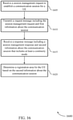
- Connectivity session manager 150 may include a connectivity session manager user plan relocation component 102, which may receive a request message including a session management request for establishing a communication session for a UE 115 and first information about the communication session, identify a continuity mode based on the received session management request, select a user plane anchor to serve the communication session for the UE 115 according to the identified continuity mode, and transmit a response message based on the selected user plane anchor, the response message including a session management response and response communication session information that includes at least an indication of the identified continuity mode.
- a connectivity session manager user plan relocation component 102 may receive a request message including a session management request for establishing a communication session for a UE 115 and first information about the communication session, identify a continuity mode based on the received session management request, select a user plane anchor to serve the communication session for the UE 115 according to the identified continuity mode, and transmit a response message based on the selected user plane anchor, the response message including a session management response and response communication session information that includes at least an indication of
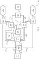
- FIG. 2 illustrates an example of a wireless communications system architecture 200 that supports a mechanism to enable optimized user plane anchoring for minimization of user plane relocation due to UE mobility in accordance with one or more aspects of the present disclosure.
- Wireless communications system architecture 200 may include UE 115-a, which may be an example of a UE 115, as described with reference to FIG. 1 .
- UE 115-a may access one or more DNs 235 (e.g., DN 235-a and DN 235-b).
- Wireless communications system architecture 200 may also include one or more devices, such as a connectivity session manager or an access and mobility manger, that may operate within the one or more DNs 235.
- UE 115-a or a DN 235 may minimize user plane relocation during UE 115-a mobility within a PDU session by utilizing a location of UE 115-a during the assignment of registration areas.
- the following management procedures may support implementation of user plane optimization within wireless communications system architecture 200.
- UE 115-a and a DN 235 may perform registration management to setup or release a signaling relation between UE 115-a and the DN 235.
- UE 115-a may register with the DN 235 to receive a specific set of services (e.g., services that require registration), enable mobility tracking, or enable reachability within the DN 235.
- UE 115-a may initiate an initial registration procedure to register to the DN 235 on an AMF 210.
- a registration timer may be associated with registration on the DN 235.
- UE 115-a may initiate a periodic registration procedure, where UE 115-a may undergo the periodic registration procedure with each expiration of the registration timer or following a predetermined time period of UE inactivity.
- UE 115-a may accordingly maintain reachability within the DN 235 based on the periodic registration procedure.
- UE 115-a may move into a new tracking area (TA) within the DN 235.
- UE 115-a may initiate a mobility registration procedure based on UE 115-a moving into the new TA.
- the DN 235 may track the location of UE 115-a and maintain reachability by registering UE 115-a in the new TA.
- UE 115-a may initiate a registration procedure with one or more DNs 235 (e.g., DNs 235-a and 235-b). UE 115-a may transmit a registration request to an access node over communication link 250, which in some cases may be an example of a (R)AN 205.
- the registration request may include an indication of the type of registration (e.g., an initial registration, a mobility registration, or a periodic registration).
- the registration request may include a subscriber permanent identifier (SUPI), a temporary user identifier (i.e., an identifier of the AMF 210 previously serving UE 115-a), security parameters, network slice selection assistance information (NSSAI), a PDU session status, or any other identifiers related to UE 115-a requesting registration in the DN 235.
- SUPI subscriber permanent identifier
- NSSAI network slice selection assistance information
- PDU session status a PDU session status
- An AMF 210 may provide registration management, connection management, reachability management, mobility management, or access authentication and authorization management for UE 115-a in the DN 235.
- the (R)AN 205 may select the AMF 210 based on the SUPI or the temporary user identifier. In other cases (e.g., if neither of these identifiers is specified or if neither indicates a valid AMF 210), the (R)AN 205 may select the AMF 210 based on the NSSAI or other policies or protocols.
- the (R)AN 205 may send the registration request to the selected AMF 210 over communication link 252.
- the (R)AN 205 may send additional parameters (e.g., location information, cell identity, radio access technology (RAT) type, etc.) to the selected AMF 210 along with the registration request.
- the selected AMF 210 may perform various procedures (e.g., as described in further detail below) based on policies, protocols, or received information.
- the selected AMF 210 may transmit a registration accept message to UE 115-a over communication link 254 via a transmitting device or via the (R)AN 205 indicating that the registration has been accepted.
- the registration accept message may include a temporary user identifier, a registration area (i.e., a TA identifier list), applicable mobility restrictions, a PDU session status, NSSAI, a periodic registration update timer, or any other identifiers related to UE 115-a registering in the DN 235.
- UE 115-a may transmit a registration complete message over communication link 254 to the selected AMF 210 to acknowledge the registration.
- the (R)AN 205 may select a different AMF 210 than the AMF 210 previously serving UE 115-a.
- the selected AMF 210 may send an information request, which may include the registration request, to the previous AMF 210 (not shown).
- the previous AMF 210 may send an information response to the selected AMF 210.
- the information response may include a SUPI for UE 115-a, a mobility management context, active PDU session information (e.g., SMF 225 identities and PDU session identities), or a combination of this information.
- the selected AMF 210 may send an information acknowledged message to the previous AMF 210 in response.
- the selected AMF 210 may not receive the SUPI (e.g., from either the previous AMF 210 or the (R)AN 205).
- the selected AMF 210 may transmit an identity request to UE 115-a, and UE 115-a may transmit an identity response back to the selected AMF 210, including the SUPI for UE 115-a.
- the selected AMF 210 may select an authentication server function (AUSF) 220 (e.g., based on the SUPI) for authentication and security functionality.
- the AUSF 220 may initiate authentication of UE 115-a and non-access stratum (NAS) security functions based on a request from the selected AMF 210 over communication link 256.
- the AUSF 220 may be based on information stored in a unified data manager (UDM) 215.
- UDM unified data manager
- the AUSF 220 may retrieve information from the UDM 215 over communication link 258. If the AUSF 220 fails, the selected AMF 210 may reject the registration request.
- the selected AMF 210 may select a UDM 215 (e.g., based on the SUPI for UE 115-a).
- the selected AMF 210 may initiate an update location procedure over communication link 260 (e.g., if the AMF 210 has changed since the previous registration procedure, if the selected AMF 210 has no valid subscription context for UE 115-a, or if UE 115-a provides an invalid SUPI to the selected AMF 210).
- the UDM 215 may initiate a cancel location procedure to the previous AMF 210.
- the previous AMF 210 may remove a mobility management context and send notifications to one or more SMFs 225 associated with the previous AMF 210.
- the selected UDM 215 may send AMF 210 related subscription data to the selected AMF 210, and the selected AMF 210 may create a mobility management context.
- the selected AMF 210 may select a policy control function (PCF) 240 (e.g., based on the SUPI for UE 115-a).
- the selected AMF 210 may send a UE context establishment request to the PCF 240 over communication link 262.
- the PCF 240 may apply operator policies for UE 115-a in the DN 235 based on the UE context establishment request, and may send a UE context establishment acknowledgment to the selected AMF 210 in response.
- the PCF 240 may have established a UE context based on a request from a previous AMF 210.
- the previous AMF 210 may send a UE context termination request to the PCF 240.
- the PCF 240 may remove the UE context for the previous AMF 210, and may send a UE context termination acknowledgment to the previous AMF 210 in response.
- an SMF 225 may initiate a user plane resource establishment based on the PDU session establishment request by the DN 235 or on a service request message.
- the AMF 210 may respond to a service request message from UE 115-a with a service response message.
- the service response message may synchronize a PDU session status between UE 115-a and a DN 235.
- the AMF 210 may respond to the service request message with a service reject message if the DN 235 does not accept the service request message from UE 115-a.
- the DN 235 may take further actions to receive the user data from UE 115-a.
- the SMF 225 may manage a PDU session, select and control a user plane anchor, such as a UPF 230 for the PDU session (e.g., using communication links 266), maintain a connection 268 (i.e., a tunnel) between the UPF 230 and a (R)AN 205 node, and provide roaming functionality to UE 115-a.
- a user plane anchor such as a UPF 230 for the PDU session (e.g., using communication links 266)
- a connection 268 i.e., a tunnel
- an SMF 225 may retrieve policy and charging control (PCC) rules from a PCF 240 over communication links 270.
- the PCC rules may be based on information the PCF 240 retrieved from an AF 245 over communication link 272.
- the SMF 225 may determine whether a request by UE 115-a is compliant with a user subscription.
- UE 115-a may establish multiple PDU sessions.
- the multiple PDU sessions may be between UE 115-a and one or more DNs 235.
- UE 115-a may establish multiple PDU sessions with a same DN 235, where the multiple PDU sessions may be served by different UPFs 230.
- Different SMFs 225 may also serve UE 115-a for the multiple PDU sessions.
- a UE 115 with multiple PDU sessions (e.g., with one or more DNNs) may use different (R)ANs 205 or UPFs 230 to interface with the one or more DNs 235.
- UE 115-a may release the PDU session and establish a new PDU session using the new UPF 230. In other cases, UE 115-a may switch to the new UPF 230 while maintaining the same PDU session.
- the DN 235 may allocate an IP address for the different connection or registration with the new UPF 230 before releasing the IP address for the previous UPF 230.
- UE 115-a may establish a new PDU session with an SSC mode that matches the identified SSC mode associated with the application.
- UE 115-a may not identify an SSC mode for the application, and may request a PDU session without providing an SSC mode. In these cases, the DN 235 may determine the SSC mode for the PDU session.
- An SMF 225 may select an SSC mode for a PDU session.
- the SMF 225 may receive a list of supported SSC modes and a default SSC mode for each DNN from a UDM 215 (e.g., within subscription information).
- the SMF 225 may receive an SSC mode from UE 115-a in a PDU session establishment request.
- the SMF 225 may select the SSC mode for the PDU session based on the received SSC mode, or the SMF 225 may modify the received SSC mode based on subscription information or local configurations.
- UE 115-a may not provide an SSC mode in the PDU session establishment request.
- the SMF 225 may select an SSC mode for the PDU session based on a default SSC mode for the DN 235, or based on local configurations and policies.
- an SMF 225 may select UPFs 230 to serve a PDU session for UE 115-a based on various information and policies.
- a UPF 230 may be located close to (R)AN 205.
- R the user plane for certain PDU sessions
- UE 115-a When UE 115-a enters an idle state in a uniform UPF serving area, UE 115-a may move within the registration area without a relocation of the UPF 230 when UE 115-a performs a service request. In this case, the entire registration area may be considered part of the UPF "serving area" for a respective DN 235.
- the network when UE 115-a enters a connected mode by performing a service request (e.g., following UE mobility in an idle mode), after having moved within the registration area, the network may trigger a relocation of the UPF 230 serving the PDU session for UE 115-a.
- the registration area may span the "serving areas" of different UPFs 230 for the DN 235.
- a delay introduced by the relocation of the UPF 230 upon performing the service request may not be acceptable, such as for some services corresponding to specific PDU sessions, and may lead to inefficient communications and a degraded user experience.
- UE 115-a may also have multiple PDU sessions to different DNs 235.
- the multiple PDU sessions may be served by different UPFs 230 with different UPF "serving areas," and the PDU sessions may have different requirements regarding the relocation of the UPF 230.
- UE 115-a may have PDU sessions through a first and second UPF 230 (e.g., UPF 230-a and UPF 230-b), but a serving area of UPF 230-a may be different than a serving area of the UPF 230-b, and the respective "serving areas" may be different sizes.
- a mechanism to prevent UE 115-a from having to establish a new or different PDU sessions may be desirable, and may result in efficient communication for UE 115-a.
- An AMF 210 and an SMF 225 may minimize user plane relocation in a PDU session by sending UE 115 and UPF 230 location information to each other.
- the AMF 210 may include a UE location indication in a session management (SM) message to the SMF 225.
- the UE location indication may be an example of a TAI, a cell identifier, a session area code value such as a PDU session area code (PSAC) value, or any other identifier associated with a position of the UE 115 (e.g., UE 115-a).
- PSAC PDU session area code
- the SMF 225 may select one or more UPFs 230 to serve UE 115-a in a PDU session.
- the SMF 225 may select the one or more UPFs 230 based on the UE location indication received from the AMF 210.
- the SMF 225 may then send PDU session information to the AMF 210.
- the PDU session information may include a UPF 230 location indication and an assigned SSC mode for the PDU session.
- the AMF 210 may assign a registration area (i.e., a TA list) to UE 115-a based on the PDU session information.
- the AMF 210 may determine a registration area based on the location of a UPF 230 (e.g., to minimize the probability of UPF relocation for UE 115-a).
- the AMF 210 may determine the registration area based on the SSC mode (e.g., if Mode 1 is assigned to the PDU session, the AMF 210 may not base the registration on mobility-based UPF relocation).
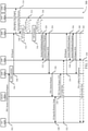
- FIG. 3 illustrates an example of a process flow 300 that supports a mechanism to enable optimized user plane anchoring for minimization of user plane relocation due to UE mobility in accordance with one or more aspects of the present disclosure.
- Process flow 300 may include (R)AN 205-a, AMF 210-a, UPF 230-c, SMF 225-c, PCF 240-a, and UDM 215-a, which may be examples of the corresponding devices as described with reference to FIG. 2 .
- Process flow 300 may also include UE 115-b, which may be an example of a UE 115 or UE 115-a, as described with reference to FIGs. 1 and 2 .
- UE 115-b implementing user plane optimization with UE and UPF location information may initiate a modified PDU session establishment procedure to establish an association with a DN.
- Process flow 300 may illustrate a PDU session establishment procedure using various options for user plane relocation minimization. For instance, in a first option, a registration area may be determined by AMF 210-a (e.g., based on UE location information) that is included in an SM request, and SMF 225-c may select a user plane anchor to match the registration area included in the SM request.
- AMF 210-a e.g., based on UE location information
- SMF 225-c may select a user plane anchor to match the registration area included in the SM request.
- the SM request (or a PDU session establishment request) includes the UE location information (e.g., a registration area, a cell identifier, a PSAC value, etc.).
- AMF 210-a thus determines a registration area for UE 115-b based on the UE location information.
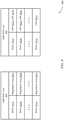
- the registration area may be selected based on an access and mobility manager session area code table, such as an AMF PSAC list, as described below.
- AMF 210-a may transmit the selected registration area to UE 115-b (e.g., via (R)AN 205-a).
- SMF 225-c may optionally send a subscription data request, including a SUPI and a DNN, to UDM 215-a. In some cases (e.g., if SMF 225-c previously retrieved SM-related subscription data for UE 115-b related to the DNN), SMF 225-c may refrain from sending this request.
- UDM 215-a may send a subscription data response to SMF 225-c.
- the subscription data response may include user subscription information, including one or more authorized PDU types, one or more authorized SSC modes, a default QoS profile, or a combination of this information.
- the user subscription information may also include a PDU session priority.
- SMF 225-c may receive the subscription data response, and may select a PDU session priority for the PDU session of the PDU session establishment request. For example, SMF 225-c may receive a PDU session priority in the SM request from AMF 210-a, in the subscription data response from UDM 215-a, or in both.
- SMF 225-c may determine a selected PDU session priority based on local policies and comparing the PDU session priority from UE 115-b with the PDU session priority from UDM 215-a. Additionally, SMF 225-c may determine whether the PDU session establishment request from UE 115-b is compliant with the user subscription information and any applicable local policies. If SMF 225-c determines that the PDU session establishment request is not compliant, SMF 225-c may transmit a NAS SM signal, including a PDU session rejection or a relevant SM rejection cause, to UE 115-b (e.g., via (R)AN 205-a).
- NAS SM signal including a PDU session rejection or a relevant SM rejection cause
- SMF 225-c may select a PCF (e.g., PCF 240-a). In some cases, at 314, SMF 225-c may establish a PDU-connectivity access network (PDU-CAN) session with PCF 240-a. Based on the PDU-CAN session, SMF 225-c may receive default PCC rules for the PDU session from PCF 240-a.
- PCF e.g., PCF 240-a
- PDU-CAN PDU-connectivity access network
- SMF 225-c selects a UPF (e.g., UPF 230-c) and an SSC mode for the PDU session.
- a UPF e.g., UPF 230-c
- SMF 225-c may allocate an IP address (and/or an IP prefix) for the PDU session.
- the selected UPF 230-c corresponds to a registration area selected by AMF 210-a and included with the SM request received at 306.
- SMF 225-c receives UE location information (e.g., included in the SM request from AMF 210-a at 306). SMF 225-c selects UPF 230-c based on the UE location information. For example, SMF 225-c may receive a session area code value (e.g., a PSAC value), and may select UPF 230-c based on a connectivity session manager session area code table, which may be an example of an SMF PSAC list (e.g., using the process described below with reference to SMF PSAC list 410 and FIG. 4 ) and the selected SSC mode. In some cases, SMF 225-c may receive UE location information from AMF 210-a in the SM request at 306, but may not select UPF 230-c based on the received UE location information.
- a session area code value e.g., a PSAC value
- SMF 225-c may receive UE location information from AMF 210-a in the SM request at 306,
- SMF 225-c may establish a PDU-CAN session with PCF 240-a. Based on the PDU-CAN session, SMF 225-c may receive default PCC rules for the PDU session from PCF 240-a. In some cases (e.g., if the PDU type is IPv4 or IPv6), SMF 225-c may initiate PDU-CAN session modification and may send the IP address for the PDU session to PCF 240-a.
- SMF 225-c may send a session establishment request to UPF 230-c.
- the session establishment request may include packet detection, enforcement, and reporting rules to be installed at UPF 230-c for the PDU session.
- SMF 225-c may allocate core network (CN) tunnel information. In these cases, SMF 225-c may also send the CN tunnel information to UPF 230-c with the session establishment request.
- CN core network
- UPF 230-c may send a session establishment response to SMF 225-c to acknowledge the reception of the session establishment request.
- UPF 230-c may allocate the CN tunnel information.
- UPF 230-c may also send the CN tunnel information to SMF 225-c with the session establishment response.
- SMF 225-c sends an SM request acknowledgment (ACK) to AMF 210-a.
- the SM request ACK may include a PDU session identifier, a QoS profile, CN tunnel information, and SM information including a PDU session establishment accept.
- the PDU session establishment accept may include one or more authorized QoS rules, the selected SSC mode, or both.
- AMF 210-a may provide the PDU session establishment accept to UE 115-b at a later time.
- the QoS profile when forwarded to (R)AN 205-a, may provide (R)AN 205-a with a map between one or more QoS parameters and one or more QoS identifiers.
- the CN tunnel information may correspond to a CN address of a tunnel associated with the PDU session.
- the SM request ACK may also include information identifying UE 115-b as the target of the SM request and which access to use towards UE 115-b.
- SMF 225-c may also send the selected PDU session priority to AMF 210-a.
- AMF 210-a may store an association between the received selected PDU session priority and an identifier of SMF 225-c.
- (R)AN 205-a may transmit the NAS message, including the PDU session establishment accept, received at 326 to UE 115-b.
- (R)AN 205-a may also use the PDU session identifier to indicate to UE 115-b an association between the (R)AN resources and the PDU session.
- (R)AN 205-a may send a PDU session request ACK, including (R)AN tunnel information, to AMF 210-a.
- the (R)AN tunnel information may correspond to an (R)AN address of the tunnel associated with the PDU session.
- UE 115-b may transmit first uplink data to the DN using UPF 230-c.
- AMF 210-a may send an SM request to SMF 225-c.
- the SM request may include the information SMF 225-c received from (R)AN 205-a at 330.
- modification of the existing session by SMF 225-c may include the selection of an additional UPF (e.g., another UPF 230, not shown) to serve the communication session.
- SMF 225-c may identify an additional SSC mode for an established session, and may select another user plane anchor for the additional SSC mode.
- UE 115-b may be concurrently served by multiple UPFs 230 (and multiple user plane anchors).
- SMF 225-c may transmit a message to AMF 210-a (and to UE 115-b) based on the additional user plane anchor selected for the session.
- UPF 230-c may send a response to SMF 225-c. For example, if UPF 230-c received a session establishment request at 336, UPF 230-c may send a session establishment response. In another example, if UPF 230-c received a session modification request at 336, UPF 230-c may send a session modification response. In some cases, UPF 230-c may modify its functionality based on the (R)AN tunnel information, the CN tunnel information, or both.
- SMF 225-c may send an SM request acknowledgment, including identifiers for the SMF and the PDU session, to AMF 210-a.
- AMF 210-a may receive the SM request acknowledgment, and may store an association of the PDU session and the SMF identifier. The association may correspond to this PDU session for UE 115-b. Based on the stored association, AMF 210-a may forward relevant events (e.g., any events associated with the PDU session, such as a change in the (R)AN tunnel information or a relocation of AMF 210-a) to SMF 225-c.
- relevant events e.g., any events associated with the PDU session, such as a change in the (R)AN tunnel information or a relocation of AMF 210-a
- AMF 210-a may send an SM request, including the PDU session establishment request within SM NAS information, to SMF 225-c.
- AMF 210-a may refrain from selecting a registration area when sending the SM request. For instance, AMF 210-a may wait to obtain information from SMF 225-c before determining a registration area.
- the SM request may not include an indication of a selected registration area in the SM request.
- SMF 225-c may send a subscription data request, including a SUPI and a DNN, to UDM 215-a. In some cases (e.g., if SMF 225-c previously retrieved SM-related subscription data for UE 115-b related to the DNN), SMF 225-c may not send this request.
- SMF 225-c may select a UPF (e.g., UPF 230-c) and an SSC mode for the PDU session.
- UPF e.g., UPF 230-c
- SMF 225-c may allocate an IP address (and/or IP prefix) for the PDU session.
- SMF 225-c may select UPF 230-c based on local policies, UE subscription information, or any other information relevant to UPF selection. That is, SMF 225-c may not receive UE location information from AMF 210-a included in the SM request at 306. In some cases, SMF 225-c may select UPF 230-c for a specific area.
- UPF 230-c may send a session establishment response to SMF 225-c to acknowledge the reception of the session establishment request.
- SMF 225-c may send an SM request acknowledgment to AMF 210-a.
- SMF 225-c may provide information regarding a serving area (e.g., associated with a user plane anchor) to AMF 210-a.
- SMF 225-c may send UPF location information, such as a PSAC value, to AMF 210-a with the SM request acknowledgment (e.g., if SMF 225-c did not receive a PSAC value from AMF 210-a, or if SMF 225-c received a PSAC value from AMF 210-a but selected a UPF that did not correspond to the PSAC value).
- the SM request ACK may include a PDU session identifier, a QoS profile, CN tunnel information, and SM information including a PDU session establishment accept.
- the PSAC value may correspond to a "serving area" of selected UPF 230-c (e.g., based on an SMF PSAC list).
- the AMF may determine a registration area 420 based on the received PSAC value 415 and SSC mode. For example, the AMF may identify registration area 420-b indicated by received PSAC value 415-b in the AMF PSAC list 405, and may determine whether indicated registration area 420-b is sufficient for the UE 115 based on the SSC mode. If the AMF does not receive a PSAC value 415 from the SMF, the AMF may determine that the SMF selected a UPF 425 based on the PSAC value 415 the AMF sent to the SMF.
- the AMF may identify a registration area 420 indicated by the PSAC value 415 the AMF sent to the SMF (e.g., if the AMF sent PSAC value 415-a to the SMF, and did not receive a PSAC value 415 back from the SMF, the AMF may identify registration area 420-a based on PSAC value 415-a).
- the AMF may transmit the identified registration area 420 to the UE 115.
- the UE 115 may register in the DN with the AMF without establishing a PDU session.
- the AMF may determine a registration area 420 for the UE 115 based on AMF policies.
- the AMF may later update the registration area 420 based on PSAC values 415 when the UE 115 initiates a PDU session.
- the AMF may determine the registration area 420 for the UE 115 based on the PDU session priority. The AMF may select the PDU session with the highest PDU session priority value, and the associated registration area 420.
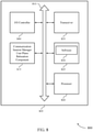
- FIG. 5 shows a block diagram 500 of a device 505 that supports a mechanism to enable optimized user plane anchoring for minimization of user plane relocation due to UE mobility in accordance with one or more aspects of the present disclosure.
- Device 505 may be an example of aspects of a connectivity session manager (e.g., an SMF) as described with reference to FIGs. 1 through 3 .
- Device 505 may include receiver 510, connectivity session manager user plane relocation component 515, and transmitter 520.
- Device 505 may also include a processor. Each of these components may be in communication with one another (e.g., via one or more buses).
- Receiver 510 may receive information such as packets, user data, or control information associated with various information channels (e.g., control channels, data channels, and information related to minimization of user plane relocation due to user equipment mobility, etc.). Information may be passed on to other components of the device.
- the receiver 510 may be an example of aspects of the transceiver 835 described with reference to FIG. 8 .
- connectivity session manager user plane relocation component 515 and/or at least some of its various sub-components may be combined with one or more other hardware components, including but not limited to an input/output (I/O) component, a transceiver, a network server, another computing device, one or more other components described in the present disclosure, or a combination thereof in accordance with one or more aspects of the present disclosure.
- I/O input/output
- FIG. 6 shows a block diagram 600 of a device 605 that supports a mechanism to enable optimized user plane anchoring for minimization of user plane relocation due to UE mobility in accordance with one or more aspects of the present disclosure.
- Device 605 may be an example of aspects of a device 505 or a connectivity session manager, such as an SMF, as described with reference to FIGs. 1 , 2 , 3 , and 5 .
- Device 605 may include receiver 610, connectivity session manager user plane relocation component 615, and transmitter 620.
- Device 605 may also include a processor. Each of these components may be in communication with one another (e.g., via one or more buses).
- Connectivity session manager session area code component 740 may determine a session area code value based on the selected user plane anchor and the identified continuity mode. In some cases, determining the session area code value includes determining, using a connectivity session manager session area code table, the session area code value corresponding to the selected user plane anchor and the identified continuity mode. Connectivity session manager priority component 745 may receive a subscribed session priority from unified data management, compare the proposed session priority with the subscribed session priority, and determine the selected session priority based on the comparison.
- Transceiver 835 may communicate bi-directionally, via one or more antennas, wired, or wireless links as described above.
- the transceiver 835 may represent a wireless transceiver and may communicate bi-directionally with another wireless transceiver.
- the transceiver 835 may also include a modem to modulate the packets and provide the modulated packets to the antennas for transmission, and to demodulate packets received from the antennas.
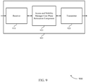
- Receiver 910 may receive information such as packets, user data, or control information associated with various information channels (e.g., control channels, data channels, and information related to minimization of user plane relocation due to user equipment mobility, etc.). Information may be passed on to other components of the device.
- the receiver 910 may be an example of aspects of the transceiver 1235 described with reference to FIG. 12 .
- Access and mobility manager user plane relocation component 915 may be an example of aspects of the access and mobility manager user plane relocation component 1215 described with reference to FIG. 12 .
- Access and mobility manager user plane relocation component 915 and/or at least some of its various sub-components may be implemented in hardware, software executed by a processor, firmware, or any combination thereof. If implemented in software executed by a processor, the functions of the access and mobility manager user plane relocation component 915 and/or at least some of its various sub-components may be executed by a general-purpose processor, a DSP, an ASIC, an FPGA or other programmable logic device, discrete gate or transistor logic, discrete hardware components, or any combination thereof designed to perform the functions described in the present disclosure.
- the access and mobility manager user plane relocation component 915 and/or at least some of its various sub-components may be physically located at various positions, including being distributed such that portions of functions are implemented at different physical locations by one or more physical devices.
- access and mobility manager user plane relocation component 915 and/or at least some of its various sub-components may be a separate and distinct component in accordance with one or more aspects of the present disclosure.
- access and mobility manager user plane relocation component 915 and/or at least some of its various sub-components may be combined with one or more other hardware components, including but not limited to an I/O component, a transceiver, a network server, another computing device, one or more other components described in the present disclosure, or a combination thereof in accordance with one or more aspects of the present disclosure.
- Transmitter 920 may transmit signals generated by other components of the device.
- the transmitter 920 may be collocated with a receiver 910 in a transceiver module.
- the transmitter 920 may be an example of aspects of the transceiver 1235 described with reference to FIG. 12 .
- the transmitter 920 may include a single antenna, or it may include a set of antennas.
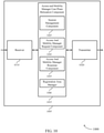
- FIG. 10 shows a block diagram 1000 of a device 1005 that supports a mechanism to enable optimized user plane anchoring for minimization of user plane relocation due to UE mobility in accordance with one or more aspects of the present disclosure.
- Device 1005 may be an example of aspects of a device 905 or an access and mobility manager (e.g., an AMF) as described with reference to FIGs. 1 , 2 , 3 , and 9 .
- Device 1005 may include receiver 1010, access and mobility manager user plane relocation component 1015, and transmitter 1020.
- Device 1005 may also include a processor. Each of these components may be in communication with one another (e.g., via one or more buses).
- Receiver 1010 may receive information such as packets, user data, or control information associated with various information channels (e.g., control channels, data channels, and information related to minimization of user plane relocation due to user equipment mobility, etc.). Information may be passed on to other components of the device.
- the receiver 1010 may be an example of aspects of the transceiver 1235 described with reference to FIG. 12 .
- Access and mobility manager user plane relocation component 1015 may be an example of aspects of the access and mobility manager user plane relocation component 1215 described with reference to FIG. 12 .
- Access and mobility manager user plane relocation component 1015 may also include session management component 1025, access and mobility manager request component 1030, access and mobility manager response component 1035, and registration area manager 1040.
- Session management component 1025 may receive a session management request to establish a communication session for a UE 115.
- Access and mobility manager request component 1030 may include the session area code value in the first information about the communication session and transmit a request message including the session management request and first information about the communication session. In some cases, the request message is transmitted to a connectivity session manager.
- Access and mobility manager response component 1035 may receive a response message including a session management response and response communication session information that includes at least a continuity mode.
- the response communication session information includes an indication of a second session area code value.
- the response communication session information includes an indication of whether the continuity mode should be considered for determining the registration area.
- the response communication session information includes a session priority associated with the communication session.
- access and mobility manager response component 1035 may receive a message for a second user plan anchor to serve the communication session for the UE.
- Registration area manager 1040 may determine a registration area for the UE 115 based on the response communication session information. In some cases, determining the registration area includes determining, using an access and mobility manager session area code table, the registration area corresponding to the first session area code value. Additionally or alternatively, determining the registration area may include determining, using the access and mobility manager session area code table, the registration area corresponding to the second session area code value. In some cases, determining the registration area includes determining the registration area based on the session priority. Registration area manager 1040 may also determine that a current registration area for the UE 115 is insufficient based on the determined registration area and the continuity mode, and transmit an updated registration area to the UE 115 based on the determination that the current registration area of the UE 115 is insufficient.
- Transmitter 1020 may transmit signals generated by other components of the device.
- the transmitter 1020 may be collocated with a receiver 1010 in a transceiver module.
- the transmitter 1020 may be an example of aspects of the transceiver 1235 described with reference to FIG. 12 .
- the transmitter 1020 may include a single antenna, or it may include a set of antennas.
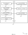
- FIG. 11 shows a block diagram 1100 of an access and mobility manager user plane relocation component 1115 that supports a mechanism to enable optimized user plane anchoring for minimization of user plane relocation due to UE mobility in accordance with one or more aspects of the present disclosure.
- the access and mobility manager user plane relocation component 1115 may be an example of aspects of an access and mobility manager user plane relocation component 1215 described with reference to FIGs. 9 , 10 , and 12 .
- the access and mobility manager user plane relocation component 1115 may include session management component 1120, access and mobility manager request component 1125, access and mobility manager response component 1130, registration area manager 1135, access and mobility manager session area code component 1140, access and mobility manager priority component 1145, and access and mobility request manager 1150. Each of these modules may communicate, directly or indirectly, with one another (e.g., via one or more buses).
- Session management component 1120 may receive a session management request to establish a communication session for a UE 115. In some cases, the session management request is received from the UE 115. Access and mobility manager request component 1125 may transmit a request message including the session management request and first information about the communication session. In some cases, the request message is transmitted to a connectivity session manager.
- Access and mobility manager response component 1130 may receive a response message including a session management response and response communication session information that includes at least a continuity mode.
- the response communication session information includes an indication of a second session area code value.
- the response communication session information includes an indication of whether the continuity mode should be considered for determining the registration area.
- the response communication session information includes a session priority associated with the communication session.
- access and mobility manager response component 1130 may receive a message for a second user plan anchor to serve the communication session for the UE.
- Access and mobility manager session area code component 1140 may determine a first session area code value associated with a location of the UE 115. In some cases, access and mobility manager session area code component 1140 may include the session area code value in the first information about the communication session. Access and mobility manager priority component 1145 may store the session priority.
- FIG. 12 shows a diagram of a system 1200 including a device 1205 that supports a mechanism to enable optimized user plane anchoring for minimization of user plane relocation due to UE mobility in accordance with one or more aspects of the present disclosure.
- Device 1205 may be an example of or include the components of access and mobility manager as described above, e.g., with reference to FIGs. 1 through 3 .
- Device 1205 may include components for bi-directional voice and data communications including components for transmitting and receiving communications, including access and mobility manager user plane relocation component 1215, processor 1220, memory 1225, software 1230, transceiver 1235, antenna 1240, and I/O controller 1245. These components may be in electronic communication via one or more busses (e.g., bus 1210).
- busses e.g., bus 1210
- FIG. 13 shows a flowchart illustrating a method 1300 for a mechanism to enable optimized user plane anchoring for minimization of user plane relocation due to UE mobility in accordance with one or more aspects of the present disclosure.
- the operations of method 1300 may be implemented by a connectivity session manager (such as an SMF) or its components as described herein.
- the operations of method 1300 may be performed by a connectivity session manager user plane relocation component as described with reference to FIGs. 5 through 8 .
- a connectivity session manager may execute a set of codes to control the functional elements of the device to perform the functions described below. Additionally or alternatively, the connectivity session manager may perform aspects of the functions described below using special-purpose hardware.
- the connectivity session manager may transmit a response message based at least in part on the selected user plane anchor, the response message comprising a session management response and response communication session information that includes at least an indication of the identified continuity mode.
- the operations of 1320 may be performed according to the methods described with reference to FIGs. 1 through 3 . In certain examples, aspects of the operations of 1320 may be performed by a connectivity session manager response component as described with reference to FIGs. 5 through 8 .
- the connectivity session manager may identify a continuity mode based at least in part on the received session management request.
- the operations of 1410 may be performed according to the methods described with reference to FIGs. 1 through 3 . In certain examples, aspects of the operations of 1410 may be performed by a connectivity session manager continuity mode component as described with reference to FIGs. 5 through 8 .
- the connectivity session manager may determine a session area code value (e.g., a PSAC value) based at least in part on the selected user plane anchor and the identified continuity mode.
- determining the session area code may include determining, using a connectivity session manager session area code table (e.g., an SMF PSAC table or list), the session area code value corresponding to the selected user plane anchor and the identified continuity mode.
- the operations of 1420 may be performed according to the methods described with reference to FIGs. 1 through 3 . In certain examples, aspects of the operations of 1420 may be performed by a connectivity session manager session area code component as described with reference to FIGs. 5 through 8 .
- the connectivity session manager may transmit, as part of the response communication session information, a selected session priority based at least in part on the proposed session priority.
- the operations of 1525 may be performed according to the methods described with reference to FIGs. 1 through 3 . In certain examples, aspects of the operations of 1525 may be performed by a connectivity session manager response component as described with reference to FIGs. 5 through 8 .
- the access and mobility manager may receive a session management request to establish a communication session for a UE 115.
- the operations of 1605 may be performed according to the methods described with reference to FIGs. 1 through 3 . In certain examples, aspects of the operations of 1605 may be performed by a session management component as described with reference to FIGs. 9 through 12 .
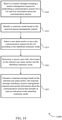
- FIG. 17 shows a flowchart illustrating a method 1700 for a mechanism to enable optimized user plane anchoring for minimization of user plane relocation due to UE mobility in accordance with one or more aspects of the present disclosure.
- the operations of method 1700 may be implemented by an access and mobility manager or its components as described herein.
- the operations of method 1700 may be performed by an access and mobility manager user plane relocation component as described with reference to FIGs. 9 through 12 .
- an access and mobility manager may execute a set of codes to control the functional elements of the device to perform the functions described below. Additionally or alternatively, the access and mobility manager may perform aspects of the functions described below using special-purpose hardware.
- the access and mobility manager may receive a session management request to establish a communication session for a UE 115.
- the operations of 1705 may be performed according to the methods described with reference to FIGs. 1 through 3 . In certain examples, aspects of the operations of 1705 may be performed by a session management component as described with reference to FIGs. 9 through 12 .
- the access and mobility manager may include the session area code value in first information about the communication session.
- the operations of 1715 may be performed according to the methods described with reference to FIGs. 1 through 3 . In certain examples, aspects of the operations of 1715 may be performed by an access and mobility manager request component as described with reference to FIGs. 9 through 12 .
- the access and mobility manager may receive a response message comprising a session management response and response communication session information that includes at least a continuity mode.
- the operations of 1725 may be performed according to the methods described with reference to FIGs. 1 through 3 . In certain examples, aspects of the operations of 1725 may be performed by an access and mobility manager response component as described with reference to FIGs. 9 through 12 .
- a CDMA system may implement a radio technology such as CDMA2000, Universal Terrestrial Radio Access (UTRA), etc.
- CDMA2000 covers IS-2000, IS-95, and IS-856 standards.
- IS-2000 Releases may be commonly referred to as CDMA2000 IX, IX, etc.
- IS-856 (TIA-856) is commonly referred to as CDMA2000 1xEV-DO, High Rate Packet Data (HRPD), etc.
- UTRA includes Wideband CDMA (WCDMA) and other variants of CDMA.
- a TDMA system may implement a radio technology such as Global System for Mobile Communications (GSM).
- GSM Global System for Mobile Communications
Landscapes
- Engineering & Computer Science (AREA)
- Computer Networks & Wireless Communication (AREA)
- Signal Processing (AREA)
- Business, Economics & Management (AREA)
- General Business, Economics & Management (AREA)
- Multimedia (AREA)
- Computer Security & Cryptography (AREA)
- Databases & Information Systems (AREA)
- Mobile Radio Communication Systems (AREA)
Claims (9)
- Procédé (1300) de communication sans fil réalisé par un gestionnaire de session de connectivité dans un réseau, le procédé comprenant les étapes consistant à :recevoir (1305) un message de demande comprenant une demande de gestion de session pour établir une session de communication pour un équipement d'utilisateur, UE, et une première information concernant la session de communication, la première information concernant la session de communication comprenant une information de localisation d'UE qui inclut une zone d'enregistrement, ladite zone d'enregistrement étant relative à une zone où peut se déplacer l'UE dans un état inactif sans avoir à effectuer de procédure de réenregistrement auprès d'un réseau ;identifier (1310) un mode de continuité sur la base, au moins en partie, de la demande de gestion de session reçue ;sélectionner (1315) un ancrage de plan d'utilisateur comportant une zone de desserte associée qui couvre la zone d'enregistrement correspondant à la localisation de l'UE pour desservir la session de communication pour l'UE selon le mode de continuité identifié ; ettransmettre (1320) un message de réponse comprenant une réponse de gestion de session et une seconde information concernant la session de communication qui inclut au moins une indication du mode de continuité identifié.
- Procédé selon la revendication 1, comprenant en outre les étapes consistant à :identifier un second mode de continuité pour la session de communication ;sélectionner un second ancrage de plan d'utilisateur pour desservir la session de communication selon le second mode de continuité identifié ; ettransmettre un message sur la base, au moins en partie, du second ancrage de plan d'utilisateur sélectionné.
- Procédé selon la revendication 1, dans lequel la sélection de l'ancrage de plan d'utilisateur comprend en outre l'étape consistant à :
déterminer l'ancrage de plan d'utilisateur sur la base, au moins en partie, d'une stratégie locale, d'un abonnement d'UE, de la première information concernant la session de communication ou d'une combinaison correspondante. - Procédé selon la revendication 1, dans lequel la première information concernant la session de communication comprend en outre une information de localisation d'UE qui inclut une identité, ID, de cellule, une valeur de code de zone de session proposée ou une combinaison correspondante.
- Procédé selon la revendication 1, dans lequel la demande de gestion de session comprend une priorité de session proposée, demandée par l'UE et associée à la session de communication, le procédé comprenant en outre l'étape consistant à :
transmettre, dans le cadre de la seconde information concernant la session de communication, une priorité de session sélectionnée sur la base, au moins en partie, de la priorité de session proposée. - Procédé selon la revendication 5, comprenant en outre l'étape consistant à :
recevoir une priorité de session abonnée en provenance d'une gestion de données unifiée. - Procédé selon la revendication 6, comprenant en outre les étapes consistant à :comparer la priorité de session proposée à la priorité de session abonnée ; etdéterminer la priorité de session sélectionnée sur la base, au moins en partie, de la comparaison.
- Procédé selon la revendication 1, dans lequel :le mode de continuité comprend une continuité de session et de service, SSC ;la session de communication comprend une session d'unité de données de protocole, PDU ;le message demandé est reçu en provenance d'un gestionnaire d'accès et de mobilité ; etle message de réponse est transmis à un gestionnaire d'accès et de mobilité.
- Gestionnaire de session de connectivité dans un réseau, le gestionnaire de session de connectivité comprenant :un moyen (625) permettant de recevoir un message de demande comprenant une demande de gestion de session pour établir une session de communication pour un équipement d'utilisateur, UE, et une première information concernant la session de communication, la première information concernant la session de communication comprenant une information de localisation d'UE qui inclut une zone d'enregistrement, ladite zone d'enregistrement étant relative à une zone où peut se déplacer l'UE dans un état inactif sans avoir à effectuer de procédure de réenregistrement auprès d'un réseau ;un moyen (630) permettant d'identifier un mode de continuité sur la base, au moins en partie, de la demande de gestion de session reçue ;un moyen (635) permettant de sélectionner un ancrage de plan d'utilisateur comportant une zone de desserte associée qui couvre la zone d'enregistrement correspondant à la localisation de l'UE pour desservir la session de communication pour l'UE selon le mode de continuité identifié ; etun moyen (640) permettant de transmettre un message de réponse comprenant une réponse de gestion de session et une seconde information concernant la session de communication qui inclut au moins une indication du mode de continuité identifié.
Applications Claiming Priority (3)
| Application Number | Priority Date | Filing Date | Title |
|---|---|---|---|
| US201762455418P | 2017-02-06 | 2017-02-06 | |
| US15/879,098 US10448239B2 (en) | 2017-02-06 | 2018-01-24 | Mechanism to enable optimized user plane anchoring for minimization of user plane relocation due to user equipment mobility |
| PCT/US2018/015192 WO2018144308A1 (fr) | 2017-02-06 | 2018-01-25 | Mécanisme pour permettre un ancrage de plan utilisateur optimisé pour la réduction au minimum d'une relocalisation de plan utilisateur due à une mobilité d'équipement utilisateur |
Publications (2)
| Publication Number | Publication Date |
|---|---|
| EP3577951A1 EP3577951A1 (fr) | 2019-12-11 |
| EP3577951B1 true EP3577951B1 (fr) | 2022-03-16 |
Family
ID=63038205
Family Applications (1)
| Application Number | Title | Priority Date | Filing Date |
|---|---|---|---|
| EP18706012.4A Active EP3577951B1 (fr) | 2017-02-06 | 2018-01-25 | Mécanisme pour permettre un ancrage de plan utilisateur optimisé pour la réduction au minimum d'une relocalisation de plan utilisateur due à une mobilité d'équipement utilisateur |
Country Status (5)
| Country | Link |
|---|---|
| US (1) | US10448239B2 (fr) |
| EP (1) | EP3577951B1 (fr) |
| CN (1) | CN110301154B (fr) |
| TW (1) | TWI701919B (fr) |
| WO (1) | WO2018144308A1 (fr) |
Families Citing this family (79)
| Publication number | Priority date | Publication date | Assignee | Title |
|---|---|---|---|---|
| CN113613293B (zh) * | 2016-07-01 | 2024-04-16 | 交互数字专利控股公司 | 用于在wtru中所使用的方法及wtru |
| EP3547769B1 (fr) | 2016-11-27 | 2021-05-12 | LG Electronics Inc. | Procédé de désenregistrement dans un système de communication sans fil et dispositif correspondant |
| US11228949B2 (en) * | 2017-01-06 | 2022-01-18 | Samsung Electronics Co., Ltd. | Intra-RAT handover for next generation system |
| JP2020057834A (ja) * | 2017-02-07 | 2020-04-09 | シャープ株式会社 | 端末装置、コアネットワーク装置、及び通信制御方法 |
| JP2020057835A (ja) * | 2017-02-07 | 2020-04-09 | シャープ株式会社 | 端末装置、コアネットワーク装置、及び通信制御方法 |
| CN112492573A (zh) * | 2017-02-21 | 2021-03-12 | 华为技术有限公司 | 一种选择会话管理功能实体的方法、装置和系统 |
| CN108512878B (zh) * | 2017-02-28 | 2021-01-29 | 华为技术有限公司 | 一种业务管理方法及其装置 |
| CN114845346B (zh) * | 2017-03-16 | 2024-04-02 | 三星电子株式会社 | 接入和移动性管理功能实体、终端及其方法 |
| CN110290471B (zh) * | 2017-03-17 | 2020-06-19 | 华为技术有限公司 | 一种会话管理功能实体及计算机可读介质 |
| RU2738262C1 (ru) * | 2017-03-18 | 2020-12-11 | Хуавэй Текнолоджиз Ко., Лтд. | Способ возобновления соединения, узел с функцией управления доступом и мобильностью и пользовательское оборудование |
| US10251147B2 (en) * | 2017-03-20 | 2019-04-02 | Samsung Electronics Co., Ltd. | Method for supporting efficient PDU session activation and deactivation in cellular networks |
| WO2018174516A1 (fr) * | 2017-03-20 | 2018-09-27 | 엘지전자(주) | Procédé de traitement de message nas dans un système de communication sans fil et appareil correspondant |
| KR102395384B1 (ko) * | 2017-03-20 | 2022-05-10 | 삼성전자 주식회사 | 셀룰러망의 효율적 pdu 세션 활성화 및 비활성화 방안 |
| AU2018240192B2 (en) * | 2017-03-20 | 2021-09-02 | Zte Corporation | Network slicing serving function |
| EP3589062B1 (fr) * | 2017-03-21 | 2021-05-12 | Huawei Technologies Co., Ltd. | Procédé et appareil de communication |
| US10575220B2 (en) | 2017-03-21 | 2020-02-25 | Electronics And Telecommunications Research Institute | Session management method based on reallocation of PDU session anchor device, and device performing the session management method |
| AU2018255075B2 (en) * | 2017-04-19 | 2020-02-06 | Lg Electronics Inc. | Method for processing PDU session establishment procedure and AMF node |
| KR102493348B1 (ko) | 2017-04-27 | 2023-01-31 | 삼성전자 주식회사 | 네트워크 슬라이스를 이용할 수 있는 지역에 대한 정보를 획득하는 방법 |
| CN113194515B (zh) * | 2017-05-05 | 2025-01-10 | 华为技术有限公司 | 一种会话管理方法、网络设备和通信系统 |
| WO2018205154A1 (fr) * | 2017-05-09 | 2018-11-15 | 华为技术有限公司 | Procédé de traitement de données, dispositif terminal et dispositif de réseau |
| CN108881356B (zh) * | 2017-05-11 | 2023-10-24 | 华为技术有限公司 | 缓存数据的方法和会话管理功能设备 |
| EP3639542B1 (fr) * | 2017-06-16 | 2023-01-04 | Telefonaktiebolaget LM Ericsson (Publ) | Réseau, noeuds de réseau, dispositifs de communication sans fil et procédé de traitement de tranches de réseau dans un réseau de communication sans fil |
| CN110771251B (zh) * | 2017-06-16 | 2023-09-22 | 艾普拉控股有限公司 | 作为通信网络中的服务的小数据传送、数据缓冲及数据管理 |
| US10171682B1 (en) * | 2017-06-30 | 2019-01-01 | Verizon Patent And Licensing Inc. | Network interface for tracking radio resource utilization |
| US11457359B2 (en) * | 2017-07-06 | 2022-09-27 | Telefonaktiebolaget Lm Ericsson (Publ) | User data transported over non-access stratum |
| CN110199513B (zh) * | 2017-07-20 | 2022-07-19 | 华为国际有限公司 | 一种会话处理方法及设备 |
| WO2019057305A1 (fr) * | 2017-09-25 | 2019-03-28 | Motorola Mobility Llc | Détermination de règles de politique dynamique dans un réseau mobile à l'aide de données d'abonnement dans un serveur d'applications |
| CN113596744B (zh) * | 2017-09-30 | 2023-11-03 | 华为技术有限公司 | 一种通信方法、装置及系统 |
| US11044773B2 (en) * | 2017-11-30 | 2021-06-22 | At&T Intellectual Property I, L.P. | Dual session packet data network connection |
| US10797894B2 (en) * | 2017-12-28 | 2020-10-06 | Ofinno, Llc | Service type and device type-based policy and charging control |
| CN110049520B (zh) * | 2018-01-15 | 2020-11-06 | 华为技术有限公司 | 通信方法和通信装置 |
| CN110120988B (zh) * | 2018-02-07 | 2021-03-30 | 华为技术有限公司 | 地址管理方法、设备及系统 |
| US12058763B2 (en) * | 2018-02-18 | 2024-08-06 | Lg Electronics Inc. | Signal transmission and reception method by SMF in wireless communication system and device therefor |
| WO2019185179A1 (fr) * | 2018-03-28 | 2019-10-03 | Telefonaktiebolaget Lm Ericsson (Publ) | Procédés et appareils permettant d'accéder à un service à l'extérieur d'un réseau de communication mobile dans une connexion par trajets multiples |
| WO2019194155A1 (fr) * | 2018-04-06 | 2019-10-10 | Nec Corporation | Procédé d'authentification pour systèmes de prochaine génération |
| US10798182B2 (en) * | 2018-05-17 | 2020-10-06 | Cisco Technology, Inc. | Application function control of IP address allocation |
| CN110830422B (zh) * | 2018-08-10 | 2022-04-01 | 中国移动通信有限公司研究院 | 一种终端行为数据处理方法及设备 |
| JP7251936B2 (ja) * | 2018-08-10 | 2023-04-04 | シャープ株式会社 | ユーザ装置、制御装置、及び通信制御方法 |
| WO2020035129A1 (fr) * | 2018-08-13 | 2020-02-20 | Huawei Technologies Co., Ltd. | Fourniture de services de multidiffusion/diffusion dans des réseaux 5g |
| KR102944291B1 (ko) | 2018-08-13 | 2026-03-26 | 삼성전자 주식회사 | 데이터 전송을 위한 PDU session 연결 관리 방법 및 장치 |
| US11115327B2 (en) * | 2018-08-24 | 2021-09-07 | Oracle International Corporation | Methods, systems, and computer readable media for providing mobile device connectivity |
| US10904827B2 (en) | 2018-09-27 | 2021-01-26 | T-Mobile Usa, Inc. | User plane system selection based on latency |
| CN110972092B (zh) * | 2018-09-30 | 2021-02-23 | 华为技术有限公司 | 本地局域网通信方法、设备及系统 |
| WO2020071888A1 (fr) * | 2018-10-05 | 2020-04-09 | Samsung Electronics Co., Ltd. | Procédé et système de dédection de serveur edge dans un réseau de télécommunication mobile |
| JP2020088472A (ja) * | 2018-11-19 | 2020-06-04 | シャープ株式会社 | ユーザ装置 |
| US20220086072A1 (en) * | 2018-12-19 | 2022-03-17 | Apple Inc. | Configuration management, performance management, and fault management to support edge computing |
| EP3909284B1 (fr) | 2019-01-08 | 2025-04-02 | Mavenir Networks, Inc. | Découverte de chemin de données de fonction de réseau optimale pour un coeur 5g |
| EP3909285B1 (fr) * | 2019-01-08 | 2025-04-02 | Mavenir Networks, Inc. | Procédé et appareil de sélection de ressource de plan utilisateur pour réseau central 5g |
| JP7274582B2 (ja) * | 2019-01-15 | 2023-05-16 | テレフオンアクチーボラゲット エルエム エリクソン(パブル) | ローカルエリアネットワーク(lan)をサポートする方法および装置 |
| WO2020167820A1 (fr) * | 2019-02-12 | 2020-08-20 | Apple Inc. | Systèmes et procédés permettant de déployer une fonction de plan d'utilisateur (upf) et des fonctions de réseau virtualisées de calcul de bord (vnf) dans des réseaux d'environnement de virtualisation de fonctions de réseau (nfv) |
| KR102704802B1 (ko) | 2019-03-04 | 2024-09-09 | 삼성전자주식회사 | 엣지 컴퓨팅 환경에서 어플리케이션 재배치를 제어하기 위한 장치 및 방법 |
| EP3963840B1 (fr) * | 2019-05-03 | 2024-10-02 | Nokia Technologies Oy | Procédé et appareil de gestion de port de passerelles ethernet |
| JP7412442B2 (ja) | 2019-05-06 | 2024-01-12 | テレフオンアクチーボラゲット エルエム エリクソン(パブル) | セッション管理のための方法及び装置 |
| CN114271016B (zh) * | 2019-06-21 | 2024-12-06 | 诺基亚技术有限公司 | 基于优先级的会话准入控制方法和装置 |
| KR102709500B1 (ko) * | 2019-09-17 | 2024-09-25 | 삼성전자주식회사 | 무선 통신 시스템에서 psa-upf 재배치를 위한 장치 및 방법 |
| WO2021063767A1 (fr) * | 2019-10-01 | 2021-04-08 | Nokia Technologies Oy | Appareil, procédé et programme informatique |
| US20220322489A1 (en) * | 2019-10-11 | 2022-10-06 | Nec Corporation | Controlling and restricting of user identities per ue |
| EP4049467B1 (fr) * | 2019-10-21 | 2024-05-15 | Lenovo (Singapore) Pte. Ltd. | Sélection du server dns en fonction de la zone de service où l'equipement utilisateur est situé |
| CN113079590B (zh) * | 2020-01-03 | 2023-01-03 | 中国移动通信有限公司研究院 | 一种服务区域切换处理方法及设备 |
| US11716308B2 (en) | 2020-03-05 | 2023-08-01 | Telefonaktiebolaget Lm Ericsson (Publ) | Application triggered setup of distributed anchor for edge computing |
| CN113473526A (zh) * | 2020-03-31 | 2021-10-01 | 华为技术有限公司 | 一种通信方法及装置 |
| JP2021175107A (ja) * | 2020-04-27 | 2021-11-01 | 日本電気株式会社 | 無線端末、センターサーバ装置、及びこれらの方法 |
| CN113873582B (zh) * | 2020-06-30 | 2023-03-28 | 华为技术有限公司 | 一种移动边缘计算处理方法以及相关设备 |
| WO2022000404A1 (fr) * | 2020-07-02 | 2022-01-06 | Qualcomm Incorporated | Techniques pour accélérer la récupération de données après une sortie du service |
| US11432350B2 (en) * | 2020-07-27 | 2022-08-30 | T-Mobile Usa, Inc. | Session management function (SMF) selection based on supported protocol type |
| US11470515B2 (en) | 2020-11-05 | 2022-10-11 | Cisco Technology, Inc. | Selection of same user plan function for user equipment movement across multiple access networks |
| US11418600B1 (en) * | 2020-12-15 | 2022-08-16 | Cisco Technology, Inc. | Session and service/flow continuity |
| AU2021420292B2 (en) * | 2021-01-14 | 2025-02-06 | Zte Corporation | Method and apparatus for survival time and communication service availability |
| WO2022179525A1 (fr) * | 2021-02-23 | 2022-09-01 | Telefonaktiebolaget Lm Ericsson (Publ) | Procédé et appareil d'authentification |
| US11716283B2 (en) | 2021-03-05 | 2023-08-01 | Oracle International Corporation | Methods, systems, and computer readable media for selecting a software defined wide area network (SD-WAN) link using network slice information |
| DE102021204143A1 (de) * | 2021-04-26 | 2022-10-27 | Volkswagen Aktiengesellschaft | Gewinnung eines Sensor-Datensatzes eines Fahrzeugs einer Fahrzeugflotte |
| US11553334B1 (en) | 2021-05-26 | 2023-01-10 | T-Mobile Innovations Llc | User equipment (UE) identification in a wireless communication network |
| CN113596957B (zh) * | 2021-07-13 | 2024-08-27 | Oppo广东移动通信有限公司 | 数据处理方法及装置、设备、存储介质 |
| CN120614573A (zh) * | 2021-08-25 | 2025-09-09 | 交互数字专利控股公司 | 对个人网络的授权、创建和管理 |
| EP4393270A4 (fr) * | 2022-01-17 | 2024-12-04 | Samsung Electronics Co., Ltd. | Procédé et appareil pour fournir des services de priorité à un ue dans un réseau sans fil |
| CN116669114A (zh) * | 2022-02-21 | 2023-08-29 | 维沃移动通信有限公司 | 信息公开的方法及通信设备 |
| CN120188462A (zh) * | 2023-03-03 | 2025-06-20 | 北京小米移动软件有限公司 | 一种算力服务调用方法、装置及存储介质 |
| KR20250024408A (ko) * | 2023-08-11 | 2025-02-18 | 삼성전자주식회사 | 펨토 기지국을 이용하는 무선 통신 시스템에서 단말의 데이터 트래픽을 전달하기 위한 네트워크를 선택하기 위한 방법 및 장치 |
| WO2025170221A1 (fr) * | 2024-02-06 | 2025-08-14 | 엘지전자 주식회사 | Communication basée sur une station de base mobile |
Family Cites Families (3)
| Publication number | Priority date | Publication date | Assignee | Title |
|---|---|---|---|---|
| CN104349374A (zh) * | 2013-08-02 | 2015-02-11 | 北京三星通信技术研究有限公司 | 异构通信系统中保持业务连续性的方法 |
| US10972552B2 (en) * | 2016-09-30 | 2021-04-06 | Huawei Technologies Co., Ltd. | Method and system for user plane path selection |
| US10531420B2 (en) * | 2017-01-05 | 2020-01-07 | Huawei Technologies Co., Ltd. | Systems and methods for application-friendly protocol data unit (PDU) session management |
-
2018
- 2018-01-24 US US15/879,098 patent/US10448239B2/en active Active
- 2018-01-25 CN CN201880009999.2A patent/CN110301154B/zh active Active
- 2018-01-25 EP EP18706012.4A patent/EP3577951B1/fr active Active
- 2018-01-25 WO PCT/US2018/015192 patent/WO2018144308A1/fr not_active Ceased
- 2018-01-25 TW TW107102686A patent/TWI701919B/zh active
Non-Patent Citations (1)
| Title |
|---|
| SAMSUNG: "Baseline description for Network Function selection", vol. SA WG2, no. Spokane, USA; 20170116 - 20170120, 16 January 2017 (2017-01-16), XP051216447, Retrieved from the Internet <URL:http://www.3gpp.org/ftp/Meetings_3GPP_SYNC/SA2/Docs/> [retrieved on 20170116] * |
Also Published As
| Publication number | Publication date |
|---|---|
| TWI701919B (zh) | 2020-08-11 |
| TW201836325A (zh) | 2018-10-01 |
| EP3577951A1 (fr) | 2019-12-11 |
| CN110301154A (zh) | 2019-10-01 |
| US20180227743A1 (en) | 2018-08-09 |
| US10448239B2 (en) | 2019-10-15 |
| WO2018144308A1 (fr) | 2018-08-09 |
| CN110301154B (zh) | 2021-07-20 |
Similar Documents
| Publication | Publication Date | Title |
|---|---|---|
| EP3577951B1 (fr) | Mécanisme pour permettre un ancrage de plan utilisateur optimisé pour la réduction au minimum d'une relocalisation de plan utilisateur due à une mobilité d'équipement utilisateur | |
| US11490436B2 (en) | User plane relocation techniques in wireless communication systems | |
| EP3471470B1 (fr) | Procédé permettant de répondre à une demande et dispositif de réseau | |
| JP7275120B2 (ja) | ネットワークスライシングと発展型パケットコア接続性との間の相互作用を可能にするためのメカニズム | |
| EP3641424B1 (fr) | Procédé d'enregistrement d'un équipement d'utilisateur avec une tranche de réseau dans un système de communication sans fil et équipement d'utilisateur pour ce procédé | |
| RU2728538C1 (ru) | Способ для выполнения связанной с регистрацией amf процедуры посредством udm в системе беспроводной связи и устройство для этого | |
| CN109964509B (zh) | 在无线通信系统中选择网络节点的方法及其设备 | |
| CN109314942B (zh) | 在无线通信系统中通过属于相同plmn的网络接入的注册方法及其设备 | |
| US10945201B2 (en) | Method for selecting PLMN of terminal in wireless communication system and apparatus for same | |
| CN109076437B (zh) | 系统信息传输方法和基站、以及系统信息接收方法和用户设备 | |
| US10470108B2 (en) | Signal transmission and reception method by remote UE in a wireless communication system and device for same | |
| US10772038B2 (en) | Method whereby terminal selects PLMN in wireless communication system, and device for same | |
| US10587656B2 (en) | Method for selecting P-CSCF and transmitting SIP message in wireless communication system and device for same | |
| EP3255929A1 (fr) | Procédé par lequel terminal sélectionne un rmtp dans un système de communication sans fil, et dispositif à cet effet | |
| CN115413059A (zh) | 用于用户设备的用于恢复小数据传输会话的装置和方法 |
Legal Events
| Date | Code | Title | Description |
|---|---|---|---|
| STAA | Information on the status of an ep patent application or granted ep patent |
Free format text: STATUS: UNKNOWN |
|
| STAA | Information on the status of an ep patent application or granted ep patent |
Free format text: STATUS: THE INTERNATIONAL PUBLICATION HAS BEEN MADE |
|
| PUAI | Public reference made under article 153(3) epc to a published international application that has entered the european phase |
Free format text: ORIGINAL CODE: 0009012 |
|
| STAA | Information on the status of an ep patent application or granted ep patent |
Free format text: STATUS: REQUEST FOR EXAMINATION WAS MADE |
|
| 17P | Request for examination filed |
Effective date: 20190627 |
|
| AK | Designated contracting states |
Kind code of ref document: A1 Designated state(s): AL AT BE BG CH CY CZ DE DK EE ES FI FR GB GR HR HU IE IS IT LI LT LU LV MC MK MT NL NO PL PT RO RS SE SI SK SM TR |
|
| AX | Request for extension of the european patent |
Extension state: BA ME |
|
| DAV | Request for validation of the european patent (deleted) | ||
| DAX | Request for extension of the european patent (deleted) | ||
| STAA | Information on the status of an ep patent application or granted ep patent |
Free format text: STATUS: EXAMINATION IS IN PROGRESS |
|
| 17Q | First examination report despatched |
Effective date: 20200826 |
|
| RIC1 | Information provided on ipc code assigned before grant |
Ipc: H04W 48/00 20090101AFI20210715BHEP Ipc: H04W 76/10 20180101ALI20210715BHEP |
|
| GRAP | Despatch of communication of intention to grant a patent |
Free format text: ORIGINAL CODE: EPIDOSNIGR1 |
|
| STAA | Information on the status of an ep patent application or granted ep patent |
Free format text: STATUS: GRANT OF PATENT IS INTENDED |
|
| INTG | Intention to grant announced |
Effective date: 20211001 |
|
| GRAS | Grant fee paid |
Free format text: ORIGINAL CODE: EPIDOSNIGR3 |
|
| GRAA | (expected) grant |
Free format text: ORIGINAL CODE: 0009210 |
|
| STAA | Information on the status of an ep patent application or granted ep patent |
Free format text: STATUS: THE PATENT HAS BEEN GRANTED |
|
| AK | Designated contracting states |
Kind code of ref document: B1 Designated state(s): AL AT BE BG CH CY CZ DE DK EE ES FI FR GB GR HR HU IE IS IT LI LT LU LV MC MK MT NL NO PL PT RO RS SE SI SK SM TR |
|
| REG | Reference to a national code |
Ref country code: GB Ref legal event code: FG4D |
|
| REG | Reference to a national code |
Ref country code: CH Ref legal event code: EP Ref country code: DE Ref legal event code: R096 Ref document number: 602018032291 Country of ref document: DE |
|
| REG | Reference to a national code |
Ref country code: IE Ref legal event code: FG4D |
|
| REG | Reference to a national code |
Ref country code: AT Ref legal event code: REF Ref document number: 1476748 Country of ref document: AT Kind code of ref document: T Effective date: 20220415 |
|
| REG | Reference to a national code |
Ref country code: LT Ref legal event code: MG9D |
|
| REG | Reference to a national code |
Ref country code: NL Ref legal event code: MP Effective date: 20220316 |
|
| PG25 | Lapsed in a contracting state [announced via postgrant information from national office to epo] |
Ref country code: SE Free format text: LAPSE BECAUSE OF FAILURE TO SUBMIT A TRANSLATION OF THE DESCRIPTION OR TO PAY THE FEE WITHIN THE PRESCRIBED TIME-LIMIT Effective date: 20220316 Ref country code: RS Free format text: LAPSE BECAUSE OF FAILURE TO SUBMIT A TRANSLATION OF THE DESCRIPTION OR TO PAY THE FEE WITHIN THE PRESCRIBED TIME-LIMIT Effective date: 20220316 Ref country code: NO Free format text: LAPSE BECAUSE OF FAILURE TO SUBMIT A TRANSLATION OF THE DESCRIPTION OR TO PAY THE FEE WITHIN THE PRESCRIBED TIME-LIMIT Effective date: 20220616 Ref country code: LT Free format text: LAPSE BECAUSE OF FAILURE TO SUBMIT A TRANSLATION OF THE DESCRIPTION OR TO PAY THE FEE WITHIN THE PRESCRIBED TIME-LIMIT Effective date: 20220316 Ref country code: HR Free format text: LAPSE BECAUSE OF FAILURE TO SUBMIT A TRANSLATION OF THE DESCRIPTION OR TO PAY THE FEE WITHIN THE PRESCRIBED TIME-LIMIT Effective date: 20220316 Ref country code: BG Free format text: LAPSE BECAUSE OF FAILURE TO SUBMIT A TRANSLATION OF THE DESCRIPTION OR TO PAY THE FEE WITHIN THE PRESCRIBED TIME-LIMIT Effective date: 20220616 |
|
| REG | Reference to a national code |
Ref country code: AT Ref legal event code: MK05 Ref document number: 1476748 Country of ref document: AT Kind code of ref document: T Effective date: 20220316 |
|
| PG25 | Lapsed in a contracting state [announced via postgrant information from national office to epo] |
Ref country code: LV Free format text: LAPSE BECAUSE OF FAILURE TO SUBMIT A TRANSLATION OF THE DESCRIPTION OR TO PAY THE FEE WITHIN THE PRESCRIBED TIME-LIMIT Effective date: 20220316 Ref country code: GR Free format text: LAPSE BECAUSE OF FAILURE TO SUBMIT A TRANSLATION OF THE DESCRIPTION OR TO PAY THE FEE WITHIN THE PRESCRIBED TIME-LIMIT Effective date: 20220617 Ref country code: FI Free format text: LAPSE BECAUSE OF FAILURE TO SUBMIT A TRANSLATION OF THE DESCRIPTION OR TO PAY THE FEE WITHIN THE PRESCRIBED TIME-LIMIT Effective date: 20220316 |
|
| PG25 | Lapsed in a contracting state [announced via postgrant information from national office to epo] |
Ref country code: NL Free format text: LAPSE BECAUSE OF FAILURE TO SUBMIT A TRANSLATION OF THE DESCRIPTION OR TO PAY THE FEE WITHIN THE PRESCRIBED TIME-LIMIT Effective date: 20220316 |
|
| PG25 | Lapsed in a contracting state [announced via postgrant information from national office to epo] |
Ref country code: SM Free format text: LAPSE BECAUSE OF FAILURE TO SUBMIT A TRANSLATION OF THE DESCRIPTION OR TO PAY THE FEE WITHIN THE PRESCRIBED TIME-LIMIT Effective date: 20220316 Ref country code: SK Free format text: LAPSE BECAUSE OF FAILURE TO SUBMIT A TRANSLATION OF THE DESCRIPTION OR TO PAY THE FEE WITHIN THE PRESCRIBED TIME-LIMIT Effective date: 20220316 Ref country code: RO Free format text: LAPSE BECAUSE OF FAILURE TO SUBMIT A TRANSLATION OF THE DESCRIPTION OR TO PAY THE FEE WITHIN THE PRESCRIBED TIME-LIMIT Effective date: 20220316 Ref country code: PT Free format text: LAPSE BECAUSE OF FAILURE TO SUBMIT A TRANSLATION OF THE DESCRIPTION OR TO PAY THE FEE WITHIN THE PRESCRIBED TIME-LIMIT Effective date: 20220718 Ref country code: ES Free format text: LAPSE BECAUSE OF FAILURE TO SUBMIT A TRANSLATION OF THE DESCRIPTION OR TO PAY THE FEE WITHIN THE PRESCRIBED TIME-LIMIT Effective date: 20220316 Ref country code: EE Free format text: LAPSE BECAUSE OF FAILURE TO SUBMIT A TRANSLATION OF THE DESCRIPTION OR TO PAY THE FEE WITHIN THE PRESCRIBED TIME-LIMIT Effective date: 20220316 Ref country code: CZ Free format text: LAPSE BECAUSE OF FAILURE TO SUBMIT A TRANSLATION OF THE DESCRIPTION OR TO PAY THE FEE WITHIN THE PRESCRIBED TIME-LIMIT Effective date: 20220316 Ref country code: AT Free format text: LAPSE BECAUSE OF FAILURE TO SUBMIT A TRANSLATION OF THE DESCRIPTION OR TO PAY THE FEE WITHIN THE PRESCRIBED TIME-LIMIT Effective date: 20220316 |
|
| PG25 | Lapsed in a contracting state [announced via postgrant information from national office to epo] |
Ref country code: PL Free format text: LAPSE BECAUSE OF FAILURE TO SUBMIT A TRANSLATION OF THE DESCRIPTION OR TO PAY THE FEE WITHIN THE PRESCRIBED TIME-LIMIT Effective date: 20220316 Ref country code: IS Free format text: LAPSE BECAUSE OF FAILURE TO SUBMIT A TRANSLATION OF THE DESCRIPTION OR TO PAY THE FEE WITHIN THE PRESCRIBED TIME-LIMIT Effective date: 20220716 Ref country code: AL Free format text: LAPSE BECAUSE OF FAILURE TO SUBMIT A TRANSLATION OF THE DESCRIPTION OR TO PAY THE FEE WITHIN THE PRESCRIBED TIME-LIMIT Effective date: 20220316 |
|
| REG | Reference to a national code |
Ref country code: DE Ref legal event code: R097 Ref document number: 602018032291 Country of ref document: DE |
|
| PLBE | No opposition filed within time limit |
Free format text: ORIGINAL CODE: 0009261 |
|
| STAA | Information on the status of an ep patent application or granted ep patent |
Free format text: STATUS: NO OPPOSITION FILED WITHIN TIME LIMIT |
|
| PG25 | Lapsed in a contracting state [announced via postgrant information from national office to epo] |
Ref country code: DK Free format text: LAPSE BECAUSE OF FAILURE TO SUBMIT A TRANSLATION OF THE DESCRIPTION OR TO PAY THE FEE WITHIN THE PRESCRIBED TIME-LIMIT Effective date: 20220316 |
|
| 26N | No opposition filed |
Effective date: 20221219 |
|
| PG25 | Lapsed in a contracting state [announced via postgrant information from national office to epo] |
Ref country code: SI Free format text: LAPSE BECAUSE OF FAILURE TO SUBMIT A TRANSLATION OF THE DESCRIPTION OR TO PAY THE FEE WITHIN THE PRESCRIBED TIME-LIMIT Effective date: 20220316 |
|
| PG25 | Lapsed in a contracting state [announced via postgrant information from national office to epo] |
Ref country code: IT Free format text: LAPSE BECAUSE OF FAILURE TO SUBMIT A TRANSLATION OF THE DESCRIPTION OR TO PAY THE FEE WITHIN THE PRESCRIBED TIME-LIMIT Effective date: 20220316 |
|
| REG | Reference to a national code |
Ref country code: CH Ref legal event code: PL |
|
| PG25 | Lapsed in a contracting state [announced via postgrant information from national office to epo] |
Ref country code: LU Free format text: LAPSE BECAUSE OF NON-PAYMENT OF DUE FEES Effective date: 20230125 |
|
| REG | Reference to a national code |
Ref country code: BE Ref legal event code: MM Effective date: 20230131 |
|
| PG25 | Lapsed in a contracting state [announced via postgrant information from national office to epo] |
Ref country code: LI Free format text: LAPSE BECAUSE OF NON-PAYMENT OF DUE FEES Effective date: 20230131 Ref country code: CH Free format text: LAPSE BECAUSE OF NON-PAYMENT OF DUE FEES Effective date: 20230131 |
|
| PG25 | Lapsed in a contracting state [announced via postgrant information from national office to epo] |
Ref country code: BE Free format text: LAPSE BECAUSE OF NON-PAYMENT OF DUE FEES Effective date: 20230131 |
|
| PG25 | Lapsed in a contracting state [announced via postgrant information from national office to epo] |
Ref country code: IE Free format text: LAPSE BECAUSE OF NON-PAYMENT OF DUE FEES Effective date: 20230125 |
|
| PG25 | Lapsed in a contracting state [announced via postgrant information from national office to epo] |
Ref country code: MC Free format text: LAPSE BECAUSE OF FAILURE TO SUBMIT A TRANSLATION OF THE DESCRIPTION OR TO PAY THE FEE WITHIN THE PRESCRIBED TIME-LIMIT Effective date: 20220316 |
|
| PG25 | Lapsed in a contracting state [announced via postgrant information from national office to epo] |
Ref country code: MC Free format text: LAPSE BECAUSE OF FAILURE TO SUBMIT A TRANSLATION OF THE DESCRIPTION OR TO PAY THE FEE WITHIN THE PRESCRIBED TIME-LIMIT Effective date: 20220316 |
|
| PG25 | Lapsed in a contracting state [announced via postgrant information from national office to epo] |
Ref country code: CY Free format text: LAPSE BECAUSE OF FAILURE TO SUBMIT A TRANSLATION OF THE DESCRIPTION OR TO PAY THE FEE WITHIN THE PRESCRIBED TIME-LIMIT; INVALID AB INITIO Effective date: 20180125 |
|
| PG25 | Lapsed in a contracting state [announced via postgrant information from national office to epo] |
Ref country code: HU Free format text: LAPSE BECAUSE OF FAILURE TO SUBMIT A TRANSLATION OF THE DESCRIPTION OR TO PAY THE FEE WITHIN THE PRESCRIBED TIME-LIMIT; INVALID AB INITIO Effective date: 20180125 |
|
| PG25 | Lapsed in a contracting state [announced via postgrant information from national office to epo] |
Ref country code: TR Free format text: LAPSE BECAUSE OF FAILURE TO SUBMIT A TRANSLATION OF THE DESCRIPTION OR TO PAY THE FEE WITHIN THE PRESCRIBED TIME-LIMIT Effective date: 20220316 |
|
| PGFP | Annual fee paid to national office [announced via postgrant information from national office to epo] |
Ref country code: GB Payment date: 20251211 Year of fee payment: 9 |
|
| PGFP | Annual fee paid to national office [announced via postgrant information from national office to epo] |
Ref country code: FR Payment date: 20251216 Year of fee payment: 9 |
|
| PGFP | Annual fee paid to national office [announced via postgrant information from national office to epo] |
Ref country code: DE Payment date: 20251222 Year of fee payment: 9 |