EP3577997B1 - Autonome uplink-übertragungstechniken mit gemeinsamem hochfrequenzspektrum - Google Patents
Autonome uplink-übertragungstechniken mit gemeinsamem hochfrequenzspektrum Download PDFInfo
- Publication number
- EP3577997B1 EP3577997B1 EP18706596.6A EP18706596A EP3577997B1 EP 3577997 B1 EP3577997 B1 EP 3577997B1 EP 18706596 A EP18706596 A EP 18706596A EP 3577997 B1 EP3577997 B1 EP 3577997B1
- Authority
- EP
- European Patent Office
- Prior art keywords
- uplink transmission
- uplink
- transmission
- radio frequency
- transmissions
- Prior art date
- Legal status (The legal status is an assumption and is not a legal conclusion. Google has not performed a legal analysis and makes no representation as to the accuracy of the status listed.)
- Active
Links
Images









Classifications
-
- H—ELECTRICITY
- H04—ELECTRIC COMMUNICATION TECHNIQUE
- H04W—WIRELESS COMMUNICATION NETWORKS
- H04W72/00—Local resource management
- H04W72/12—Wireless traffic scheduling
- H04W72/1215—Wireless traffic scheduling for collaboration of different radio technologies
-
- H—ELECTRICITY
- H04—ELECTRIC COMMUNICATION TECHNIQUE
- H04W—WIRELESS COMMUNICATION NETWORKS
- H04W74/00—Wireless channel access
- H04W74/08—Non-scheduled access, e.g. ALOHA
- H04W74/0808—Non-scheduled access, e.g. ALOHA using carrier sensing, e.g. carrier sense multiple access [CSMA]
- H04W74/0816—Non-scheduled access, e.g. ALOHA using carrier sensing, e.g. carrier sense multiple access [CSMA] with collision avoidance
-
- H—ELECTRICITY
- H04—ELECTRIC COMMUNICATION TECHNIQUE
- H04L—TRANSMISSION OF DIGITAL INFORMATION, e.g. TELEGRAPHIC COMMUNICATION
- H04L1/00—Arrangements for detecting or preventing errors in the information received
- H04L1/0001—Systems modifying transmission characteristics according to link quality, e.g. power backoff
- H04L1/0023—Systems modifying transmission characteristics according to link quality, e.g. power backoff characterised by the signalling
- H04L1/0026—Transmission of channel quality indication
-
- H—ELECTRICITY
- H04—ELECTRIC COMMUNICATION TECHNIQUE
- H04L—TRANSMISSION OF DIGITAL INFORMATION, e.g. TELEGRAPHIC COMMUNICATION
- H04L1/00—Arrangements for detecting or preventing errors in the information received
- H04L1/0001—Systems modifying transmission characteristics according to link quality, e.g. power backoff
- H04L1/0023—Systems modifying transmission characteristics according to link quality, e.g. power backoff characterised by the signalling
- H04L1/0028—Formatting
- H04L1/0031—Multiple signaling transmission
-
- H—ELECTRICITY
- H04—ELECTRIC COMMUNICATION TECHNIQUE
- H04L—TRANSMISSION OF DIGITAL INFORMATION, e.g. TELEGRAPHIC COMMUNICATION
- H04L1/00—Arrangements for detecting or preventing errors in the information received
- H04L1/004—Arrangements for detecting or preventing errors in the information received by using forward error control
- H04L1/0056—Systems characterized by the type of code used
- H04L1/0067—Rate matching
-
- H—ELECTRICITY
- H04—ELECTRIC COMMUNICATION TECHNIQUE
- H04L—TRANSMISSION OF DIGITAL INFORMATION, e.g. TELEGRAPHIC COMMUNICATION
- H04L1/00—Arrangements for detecting or preventing errors in the information received
- H04L1/12—Arrangements for detecting or preventing errors in the information received by using return channel
- H04L1/16—Arrangements for detecting or preventing errors in the information received by using return channel in which the return channel carries supervisory signals, e.g. repetition request signals
- H04L1/1607—Details of the supervisory signal
- H04L1/1614—Details of the supervisory signal using bitmaps
-
- H—ELECTRICITY
- H04—ELECTRIC COMMUNICATION TECHNIQUE
- H04L—TRANSMISSION OF DIGITAL INFORMATION, e.g. TELEGRAPHIC COMMUNICATION
- H04L1/00—Arrangements for detecting or preventing errors in the information received
- H04L1/12—Arrangements for detecting or preventing errors in the information received by using return channel
- H04L1/16—Arrangements for detecting or preventing errors in the information received by using return channel in which the return channel carries supervisory signals, e.g. repetition request signals
- H04L1/18—Automatic repetition systems, e.g. Van Duuren systems
- H04L1/1812—Hybrid protocols; Hybrid automatic repeat request [HARQ]
- H04L1/1819—Hybrid protocols; Hybrid automatic repeat request [HARQ] with retransmission of additional or different redundancy
-
- H—ELECTRICITY
- H04—ELECTRIC COMMUNICATION TECHNIQUE
- H04L—TRANSMISSION OF DIGITAL INFORMATION, e.g. TELEGRAPHIC COMMUNICATION
- H04L1/00—Arrangements for detecting or preventing errors in the information received
- H04L1/12—Arrangements for detecting or preventing errors in the information received by using return channel
- H04L1/16—Arrangements for detecting or preventing errors in the information received by using return channel in which the return channel carries supervisory signals, e.g. repetition request signals
- H04L1/18—Automatic repetition systems, e.g. Van Duuren systems
- H04L1/1822—Automatic repetition systems, e.g. Van Duuren systems involving configuration of automatic repeat request [ARQ] with parallel processes
-
- H—ELECTRICITY
- H04—ELECTRIC COMMUNICATION TECHNIQUE
- H04L—TRANSMISSION OF DIGITAL INFORMATION, e.g. TELEGRAPHIC COMMUNICATION
- H04L27/00—Modulated-carrier systems
- H04L27/26—Systems using multi-frequency codes
- H04L27/2601—Multicarrier modulation systems
- H04L27/2647—Arrangements specific to the receiver only
- H04L27/2655—Synchronisation arrangements
- H04L27/2662—Symbol synchronisation
-
- H—ELECTRICITY
- H04—ELECTRIC COMMUNICATION TECHNIQUE
- H04L—TRANSMISSION OF DIGITAL INFORMATION, e.g. TELEGRAPHIC COMMUNICATION
- H04L5/00—Arrangements affording multiple use of the transmission path
- H04L5/003—Arrangements for allocating sub-channels of the transmission path
- H04L5/0053—Allocation of signalling, i.e. of overhead other than pilot signals
- H04L5/0055—Physical resource allocation for ACK/NACK
-
- H—ELECTRICITY
- H04—ELECTRIC COMMUNICATION TECHNIQUE
- H04L—TRANSMISSION OF DIGITAL INFORMATION, e.g. TELEGRAPHIC COMMUNICATION
- H04L5/00—Arrangements affording multiple use of the transmission path
- H04L5/003—Arrangements for allocating sub-channels of the transmission path
- H04L5/0078—Timing of allocation
-
- H—ELECTRICITY
- H04—ELECTRIC COMMUNICATION TECHNIQUE
- H04L—TRANSMISSION OF DIGITAL INFORMATION, e.g. TELEGRAPHIC COMMUNICATION
- H04L5/00—Arrangements affording multiple use of the transmission path
- H04L5/0091—Signalling for the administration of the divided path, e.g. signalling of configuration information
- H04L5/0094—Indication of how sub-channels of the path are allocated
-
- H—ELECTRICITY
- H04—ELECTRIC COMMUNICATION TECHNIQUE
- H04W—WIRELESS COMMUNICATION NETWORKS
- H04W72/00—Local resource management
- H04W72/12—Wireless traffic scheduling
- H04W72/1263—Mapping of traffic onto schedule, e.g. scheduled allocation or multiplexing of flows
- H04W72/1268—Mapping of traffic onto schedule, e.g. scheduled allocation or multiplexing of flows of uplink data flows
-
- H—ELECTRICITY
- H04—ELECTRIC COMMUNICATION TECHNIQUE
- H04W—WIRELESS COMMUNICATION NETWORKS
- H04W72/00—Local resource management
- H04W72/20—Control channels or signalling for resource management
- H04W72/21—Control channels or signalling for resource management in the uplink direction of a wireless link, i.e. towards the network
-
- H—ELECTRICITY
- H04—ELECTRIC COMMUNICATION TECHNIQUE
- H04W—WIRELESS COMMUNICATION NETWORKS
- H04W74/00—Wireless channel access
- H04W74/002—Transmission of channel access control information
-
- H—ELECTRICITY
- H04—ELECTRIC COMMUNICATION TECHNIQUE
- H04W—WIRELESS COMMUNICATION NETWORKS
- H04W74/00—Wireless channel access
- H04W74/002—Transmission of channel access control information
- H04W74/004—Transmission of channel access control information in the uplink, i.e. towards network
-
- H—ELECTRICITY
- H04—ELECTRIC COMMUNICATION TECHNIQUE
- H04W—WIRELESS COMMUNICATION NETWORKS
- H04W74/00—Wireless channel access
- H04W74/002—Transmission of channel access control information
- H04W74/006—Transmission of channel access control information in the downlink, i.e. towards the terminal
-
- H—ELECTRICITY
- H04—ELECTRIC COMMUNICATION TECHNIQUE
- H04L—TRANSMISSION OF DIGITAL INFORMATION, e.g. TELEGRAPHIC COMMUNICATION
- H04L1/00—Arrangements for detecting or preventing errors in the information received
- H04L1/0001—Systems modifying transmission characteristics according to link quality, e.g. power backoff
- H04L1/0002—Systems modifying transmission characteristics according to link quality, e.g. power backoff by adapting the transmission rate
- H04L1/0003—Systems modifying transmission characteristics according to link quality, e.g. power backoff by adapting the transmission rate by switching between different modulation schemes
-
- H—ELECTRICITY
- H04—ELECTRIC COMMUNICATION TECHNIQUE
- H04L—TRANSMISSION OF DIGITAL INFORMATION, e.g. TELEGRAPHIC COMMUNICATION
- H04L1/00—Arrangements for detecting or preventing errors in the information received
- H04L1/0001—Systems modifying transmission characteristics according to link quality, e.g. power backoff
- H04L1/0009—Systems modifying transmission characteristics according to link quality, e.g. power backoff by adapting the channel coding
-
- H—ELECTRICITY
- H04—ELECTRIC COMMUNICATION TECHNIQUE
- H04L—TRANSMISSION OF DIGITAL INFORMATION, e.g. TELEGRAPHIC COMMUNICATION
- H04L5/00—Arrangements affording multiple use of the transmission path
- H04L5/003—Arrangements for allocating sub-channels of the transmission path
- H04L5/0053—Allocation of signalling, i.e. of overhead other than pilot signals
-
- H—ELECTRICITY
- H04—ELECTRIC COMMUNICATION TECHNIQUE
- H04W—WIRELESS COMMUNICATION NETWORKS
- H04W28/00—Network traffic management; Network resource management
- H04W28/02—Traffic management, e.g. flow control or congestion control
- H04W28/06—Optimizing the usage of the radio link, e.g. header compression, information sizing, discarding information
-
- H—ELECTRICITY
- H04—ELECTRIC COMMUNICATION TECHNIQUE
- H04W—WIRELESS COMMUNICATION NETWORKS
- H04W72/00—Local resource management
- H04W72/20—Control channels or signalling for resource management
- H04W72/23—Control channels or signalling for resource management in the downlink direction of a wireless link, i.e. towards a terminal
-
- H—ELECTRICITY
- H04—ELECTRIC COMMUNICATION TECHNIQUE
- H04W—WIRELESS COMMUNICATION NETWORKS
- H04W74/00—Wireless channel access
- H04W74/08—Non-scheduled access, e.g. ALOHA
- H04W74/0808—Non-scheduled access, e.g. ALOHA using carrier sensing, e.g. carrier sense multiple access [CSMA]
Definitions
- Wireless communications systems are widely deployed to provide various types of communication content such as voice, video, packet data, messaging, broadcast, and so on. These systems may be capable of supporting communication with multiple users by sharing the available system resources (e.g., time, frequency, and power).
- multiple-access systems include code division multiple access (CDMA) systems, time division multiple access (TDMA) systems, frequency division multiple access (FDMA) systems, and orthogonal frequency division multiple access (OFDMA) systems, (e.g., a Long Term Evolution (LTE) system, or a New Radio (NR) system).
- CDMA code division multiple access
- TDMA time division multiple access
- FDMA frequency division multiple access
- OFDMA orthogonal frequency division multiple access
- LTE Long Term Evolution
- NR New Radio
- a wireless multiple-access communications system may include a number of base stations or access network nodes, each simultaneously supporting communication for multiple communication devices, which may be otherwise known as user equipment (UE).
- UE user equipment
- Some wireless systems may enable communication between a base station and a UE over shared or unlicensed radio frequency spectrum bands, or over different radio frequency spectrum bands (e.g., licensed radio frequency spectrum bands and unlicensed radio frequency spectrum bands).
- transmitters e.g., UEs, base stations, or other network access devices
- may perform contention-based channel access e.g., by performing a listen before talk (LBT) procedure
- LBT listen before talk
- a base station may schedule UEs for uplink communications through an assignment or grant of resources.
- a base station may configure a UE to autonomously transmit uplink communications according to an autonomous uplink configuration. In such cases, the base station may not be aware of particular timings for uplink transmissions, due to the autonomous nature of such transmissions and due to the contention-based access to the shared radio frequency spectrum band.
- UL URLLC transmission schemes 3GPP DRAFT; R1-1612004 , describes several transmission schemes for UL URLLC transmission in wireless communication systems.
- the URLLC schemes comprise dynamic resource allocation, semi-static resource allocation, grant-free LBT-based transmission and grant-free NOMA schemes.
- the described techniques relate to improved methods, systems, devices, or apparatuses that support autonomous uplink transmissions using shared or unlicensed radio frequency spectrum.
- the described techniques provide for efficient coordination of autonomous uplink transmissions, and associated downlink transmissions through various signals, control information, waveform modification, or combinations thereof.
- unlicensed radio frequency spectrum bands may be used for Long Term Evolution (LTE) or LTE-Advanced (LTE-A) communications.
- Unlicensed radio frequency spectrum may be used in combination with, or independent from, a dedicated or licensed radio frequency spectrum band.
- the dedicated radio frequency spectrum band may include a radio frequency spectrum band licensed to particular users for particular uses.
- the unlicensed or shared radio frequency spectrum band may include a radio frequency spectrum band available for Wi-Fi use, a radio frequency spectrum band available for use by different radio access technologies, or a radio frequency spectrum band available for use by multiple mobile network operators (MNOs) in an equally shared or prioritized manner.
- MNOs mobile network operators
- FIG. 1 illustrates an example of a wireless communications system 100 in accordance with various aspects of the present disclosure.
- the wireless communications system 100 includes base stations 105, UEs 115, and a core network 130.
- the wireless communications system 100 may be a LTE (or LTE-Advanced) network, or a New Radio (NR) network.
- LTE Long Term Evolution
- NR New Radio
- wireless communications system 100 may support enhanced broadband communications, ultra-reliable (i.e. , mission critical) communications, low latency communications, and communications with low-cost and low-complexity devices.
- Wireless communications system 100 may be an example of a system that supports autonomous uplink transmissions by UEs 115.
- Base stations 105 may wirelessly communicate with UEs 115 via one or more base station antennas. Each base station 105 may provide communication coverage for a respective geographic coverage area 110.
- Communication links 125 shown in wireless communications system 100 may include uplink (UL) transmissions from a UE 115 to a base station 105, or downlink (DL) transmissions, from a base station 105 to a UE 115.
- Control information and data may be multiplexed on an uplink channel or downlink according to various techniques. Control information and data may be multiplexed on a downlink channel, for example, using time division multiplexing (TDM) techniques, frequency division multiplexing (FDM) techniques, or hybrid TDM-FDM techniques.
- TDM transmission time interval
- FDM frequency division multiplexing
- hybrid TDM-FDM techniques hybrid TDM-FDM techniques.
- the control information transmitted during a transmission time interval (TTI) of a downlink channel may be distributed between different control regions in a cascaded manner (e.g., between
- a UE 115 may also be a cellular phone, a personal digital assistant (PDA), a wireless modem, a wireless communication device, a handheld device, a tablet computer, a laptop computer, a cordless phone, a personal electronic device, a handheld device, a personal computer, a wireless local loop (WLL) station, an Internet of things (IoT) device, an Internet of Everything (IoE) device, a machine type communication (MTC) device, an appliance, an automobile, or the like.
- PDA personal digital assistant
- WLL wireless local loop
- IoT Internet of things
- IoE Internet of Everything
- MTC machine type communication
- an MTC device may operate using half-duplex (one-way) communications at a reduced peak rate. MTC devices may also be configured to enter a power saving "deep sleep" mode when not engaging in active communications. In some cases, MTC or IoT devices may be designed to support mission critical functions and wireless communications system may be configured to provide ultra-reliable communications for these functions.
- Base stations 105 may communicate with the core network 130 and with one another. For example, base stations 105 may interface with the core network 130 through backhaul links 132 (e.g. , S1, etc. ) . Base stations 105 may communicate with one another over backhaul links 134 ( e.g. , X2, etc. ) either directly or indirectly ( e.g. , through core network 130). Base stations 105 may perform radio configuration and scheduling for communication with UEs 115, or may operate under the control of a base station controller (not shown). In some examples, base stations 105 may be macro cells, small cells, hot spots, or the like. Base stations 105 may also be referred to as eNodeBs (eNBs) 105.
- eNodeBs eNodeBs
- UE 115 and base station 105 may operate in a shared radio frequency spectrum band, which may include licensed RF spectrum, unlicensed RF spectrum, or a combination of licensed and unlicensed RF spectrum.
- wireless communications system 100 may employ LTE License Assisted Access (LTE-LAA) or LTE Unlicensed (LTE U) radio access technology or NR technology in an unlicensed band such as the 5 GHz Industrial, Scientific, and Medical (ISM) band.
- LTE-LAA LTE License Assisted Access
- LTE U LTE Unlicensed
- NR technology such as the 5 GHz Industrial, Scientific, and Medical (ISM) band.
- ISM 5 GHz Industrial, Scientific, and Medical
- UEs 115 or base stations 105 may traditionally perform a medium-sensing procedure to contend for access to the frequency spectrum.
- UE 115 or base station 105 may perform an LBT procedure such as a clear channel assessment (CCA) prior to communicating in order to determine whether the shared channel is available.
- CCA clear channel assessment
- AUL transmissions may follow similar LBT rules as used for grant-based uplink transmissions, such as category 4 LBT rules.
- a CCA may include an energy detection or energy sensing procedure to determine whether there are any other active transmissions. For example, each UE 115 may randomly choose a backoff counter (with may be a certain duration or a number of symbols) and listen to a channel including resources the UEs 115 are contending for until the counter decrements to zero. If the counter reaches zero for a certain UE 115 and no other transmissions are detected, the UE 115 may start transmitting. If the counter does not reach zero before another signal is detected, the UE 115 has lost contention for resource and refrains from transmitting.
- a backoff counter with may be a certain duration or a number of symbols
- a UE 115 may infer that a change in a received signal strength indicator (RSSI) of a power meter indicates that a channel is occupied. Specifically, signal power that is concentrated in a certain bandwidth and exceeds a predetermined noise floor may indicate another wireless transmitter.
- a CCA also may include detection of specific sequences that indicate use of the channel. For example, another device may transmit a specific preamble prior to transmitting a data sequence.
- an LBT procedure may include a wireless node adjusting its own backoff window based on the amount of energy detected on a channel and/or the acknowledge/negative-acknowledge (ACK/NACK) feedback for its own transmitted packets as a proxy for collisions.
- ACK/NACK acknowledge/negative-acknowledge
- Base stations 105 may wirelessly communicate with UEs 115 via one or more base station antennas. Each base station 105 may provide communication coverage for a respective geographic coverage area 110. Communication links 125 shown in wireless communications system 100 may include uplink transmissions from a UE 115 to a base station 105, or downlink transmissions, from a base station 105 to a UE 115. UEs 115 may be dispersed throughout the wireless communications system 100, and each UE 115 may be stationary or mobile. Although a base station 105 may generally refer to aspects of wireless wide area networks (WWANs) and an AP may generally refer to aspects of WLANs, base station and AP may be used interchangeably. As discussed below, a base station 105 may identify conditions (e.g ., number of hidden nodes) of a UE 115, and the core network 130, via base station 105, may configure the UE 115 accordingly.
- WWANs wireless wide area networks
- AP may generally refer to aspects of WLANs
- UEs 115 and base stations 105 may employ a hybrid automatic repeat request (HARQ) feedback mechanism, which may be a method of ensuring that data is received correctly over a communication link 125.
- HARQ may include a combination of error detection (e.g . , using a cyclic redundancy check (CRC), forward error correction (FEC), and retransmission (e.g., automatic repeat request (ARQ)).
- HARQ may improve throughput at the media access control (MAC) layer in poor radio conditions (e.g., signal-to-noise conditions).
- MAC media access control
- Incremental Redundancy HARQ incorrectly received data may be stored in a buffer and combined with subsequent transmissions to improve the overall likelihood of successfully decoding the data.
- Bidirectional communications may use frequency division duplexing (FDD) (e.g. , using paired spectrum resources) or time division duplexing (TDD) operation (e.g., using unpaired spectrum resources).
- FDD frequency division duplexing
- TDD time division duplexing
- Frame structures for FDD e.g. , frame structure type 1
- TDD time division duplexing
- Frame structures for FDD e.g. , frame structure type 1
- TDD e.g. , frame structure type 2
- special subframes may be used to switch between downlink and uplink transmission.
- Allocation of uplink and downlink subframes within radio frames may be symmetric or asymmetric and may be statically determined or may be reconfigured semi-statically.
- Special subframes may carry downlink or uplink traffic and may include a guard period (GP) between downlink and uplink traffic.
- GP guard period
- Switching from uplink to downlink traffic may be achieved by setting a timing advance at the UE 115 without the use of special subframes or a guard period.
- Uplink-downlink configurations with switch-point periodicity equal to the frame period ( e.g. , 10 ms) or half of the frame period ( e.g. , 5 ms) may also be supported.
- TDD frames may include one or more special frames, and the period between special frames may determine the TDD DL-to-UL switch-point periodicity for the frame.
- Use of TDD offers flexible deployments without requiring paired UL-DL spectrum resources.
- interference may be caused between uplink and downlink communications (e.g ., interference between uplink and downlink communication from different base stations, interference between uplink and downlink communications from base stations and UEs, etc. ) .
- a UE 115 attempting to receive and decode a downlink transmission from a serving base station 105 may experience interference from uplink transmissions from other, proximately located UEs 115.
- a UE 115 may be detectable by a central base station 105 (or AP), but not by other UEs 115 in the coverage area 110 of the central base station 105.
- one UE 115 may be at one end of the coverage area 110 of the central base station 105 while another UE 115 may be at the other end ( e.g. , a hidden node).
- both UEs 115 may communicate with the base station 105, but may not receive the transmissions of the other. This may result in colliding transmissions for the two UEs 115 in a contention based environment (e.g., carrier sense multiple access with collision avoidance (CSMA/CA)) because the UEs 115 may not refrain from transmitting on top of each other.
- CSMA/CA carrier sense multiple access with collision avoidance
- the base station 105 may have a misaligned TDD configuration and frame start-timing, which may result in a collision between the transmissions from the two UEs 115.
- a base station may enable or disable AUL transmissions at a UE 115 to reduce the likelihood of interference between multiple AUL transmissions, as will be discussed in further detail below.
- SFN system frame number
- Each frame may include ten 1 ms subframes numbered from 0 to 9.
- a subframe may be further divided into two 0.5 ms slots, each of which contains 6 or 7 modulation symbol periods (depending on the length of the cyclic prefix prepended to each symbol). Excluding the cyclic prefix, each symbol may contain 2048 sample periods.
- symbols within wireless communications system 100 may also have different durations.
- the subframe may be the smallest scheduling unit, also known as a TTI.
- a TTI may be shorter than a subframe or may be dynamically selected (e.g. , in short TTI bursts or in selected component carriers using short TTIs).
- Each frame may include ten 1 ms subframes numbered from 0 to 9; other frame structures may also be employed, as discussed below.
- a subframe may be further divided into two .5ms slots, each of which contains 6 or 7 modulation symbol periods (depending on the length of the cyclic prefix prepended to each symbol).
- a resource element may consist of one symbol period and one subcarrier (a 15 KHz frequency range).
- a resource block may contain 12 consecutive subcarriers in the frequency domain and, for a normal cyclic prefix in each orthogonal frequency division multiplexing (OFDM) symbol, 7 consecutive OFDM symbols in the time domain (1 slot), or 84 resource elements.
- OFDM orthogonal frequency division multiplexing
- wireless communications system 100 may be organized by transmission opportunities (TxOPs), which may be organized according to the frame structure described above and which a may be separated by periods of time during which the wireless medium may be unavailable for devices (e.g ., UEs 115 or base stations 105) within wireless communications system 100.
- TxOPs transmission opportunities
- wireless communications system 100 may utilize enhanced component carriers (eCCs).
- eCC may be characterized by one or more features including: wider bandwidth, shorter symbol duration, shorter transmission time interval (TTIs), and modified control channel configuration.
- an eCC may be associated with a carrier aggregation configuration or a dual connectivity configuration (e.g ., when multiple serving cells have a suboptimal or non-ideal backhaul link).
- An eCC may also be configured for use in unlicensed spectrum or shared spectrum (where more than one operator is allowed to use the spectrum).
- An eCC characterized by wide bandwidth may include one or more segments that may be utilized by UEs 115 that are not capable of monitoring the whole bandwidth or prefer to use a limited bandwidth ( e.g ., to conserve power).
- an eCC may utilize a different symbol duration than other CCs, which may include use of a reduced symbol duration as compared with symbol durations of the other CCs.
- a shorter symbol duration may be associated with increased subcarrier spacing.
- a TTI in an eCC may consist of one or multiple symbols. In some cases, the TTI duration (that is, the number of symbols in a TTI) may be variable.
- a device such as a UE 115 or base station 105, utilizing eCCs may transmit wideband signals ( e.g. , 20, 40, 60, 80 MHz, etc. ) at reduced symbol durations ( e.g. , 16.67 microseconds).
- a TTI in eCC may consist of one or multiple symbols. In some cases, the TTI duration (that is, the number of symbols in a TTI) may be variable.
- wireless communications system 100 may support different uplink transmission configurations for different UEs 115 (e.g. , mixed mode scheduling). That is, a first UE 115 may operate using AUL transmissions (which may be used in addition to scheduled uplink transmissions) and other UEs 115 may use scheduled uplink transmissions.
- mixed-mode scheduling may be associated with enhanced communications performance within the system, and a base station 105 may enable or disable AUL transmissions at different UEs 115 to provide such mixed-mode scheduling.
- configurations for UEs 115 that may operate using unscheduled and/or scheduled uplink transmissions may be determined by a serving base station 105.
- a UE 115 configured for AUL may, in some examples, perform channel contention and gain access to a shared radio frequency spectrum band, according to an AUL configuration that may be provided to the UE 115 by a base station 105.
- the UE 115 may modify an uplink waveform or provide an indication to the base station 105 of one or more channel resources that may be available for base station 150 transmissions, in order to more fully utilize shared radio frequency spectrum band resources within a MCOT.
- a CRC of a DCI may be scrambled with an identification that indicates whether AUL transmissions are activated or deactivated at a particular UE 115.
- the UE 115 and base station 105 may exchange various other control information to provide relatively efficient autonomous uplink transmissions and use of the shared radio frequency spectrum band resources, as discussed herein.
- the AUL transmissions 220 and associated control information may be transmitted between base station 105-a and UE 115-a in a manner that provides enhanced efficiency shared resources such as resources of a shared radio frequency spectrum band.
- UE 115-a may have data that is to be transmitted using an AUL transmission 220, and may determine that data to be transmitted in the AUL transmission spans less than a total duration of the transmission opportunity (TxOP) acquired by the UE 115-a as part of the channel contention process.
- the UE 115-a may signal to the base station 105-a a number of subframes of the TxOP that are unused, and that may then be used by the base station 105-a.
- both the UE 115-a and the base station 105-a may more efficiently use the shared resources and increase system throughput and efficiency.
- the AUL transmission 220 may occupy the entire TxOP or nearly the entire TxOP, and the UE 115-a may modify a waveform of the AUL transmission in order to provide a gap during which the base station 105-a may perform an LBT procedure.
- FIG. 3 illustrates an example of shared channel resources 300 that support autonomous uplink transmission techniques using shared radio frequency spectrum in accordance with various aspects of the present disclosure.
- Shared channel resources 300 may be utilized by base stations 105 and UEs 115 as described with reference to FIGs. 1 and 2 .
- regulations associated with shared channel contention procedures may specify a maximum gap between transmissions between a UE and a base station.
- ETSI regulations specify a maximum gap of 25 ⁇ s between base station and UE transmissions, and in some cases a base station may transmit a cell-specific reference signal (CRS) in a first symbol of a downlink transmission that the UE may use to detect transmission from the base station.
- CRS cell-specific reference signal
- the UE may perform a CCA 305 and gain access to the shared channel resources 300, and may transmit AUL transmission 310. Synchronized timing in the system may provide that a downlink transmission starts in a first downlink subframe 320 that is subsequent to a last uplink subframe 325. As indicated above, the UE may leave a gap 315 between the last uplink subframe 325 and the first downlink subframe 320 during which the base station may perform channel contention. Further, a maximum time period (e.g. , X ⁇ s) may be specified in certain cases.
- a maximum time period e.g. , X ⁇ s
- the UE may apply a timing advance (TA) when transmitting uplink transmissions, so as to provide uplink transmissions that arrive at the base station and provide system synchronization.
- TA may be used to compensate for propagation delay of the AUL transmission 310 between the UE and the base station, and may be determined by the UE according to established techniques for determining TA.
- a UE may modify the uplink transmission waveform, or provide signaling to a base station, that provides the gap 315 and also complies with any specified maximum time gap.
- the UE may generate an uplink waveform that spans the entire duration of the AUL transmission 310, and then puncture the last (X - TA) ⁇ s of the AUL transmission 310 in the last symbol of the last downlink subframe 325.
- the UE may generate an uplink waveform that spans a time that is one symbol less than the entire duration of the AUL transmission 310, and may cyclically extend sample of the last symbol of the waveform (X - TA) ⁇ s before the boundary of the first downlink subframe 320.
- the base station may performs the channel contention procedure and transmit a reservation signal for TA ⁇ s until the boundary of the first downlink subframe 320.
- autonomous uplink control information A-UCI
- A-UCI autonomous uplink control information
- A-PUCCH physical channel carrying A-UCI
- the base station may then perform a X ⁇ s CCA to start the downlink transmission at the first downlink subframe 320.
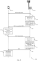
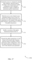
- the base station 105-b may determine an AUL configuration for the UE 115-b, and may transmit the AUL configuration 405 in a downlink transmission to the UE 115-b.
- the AUL configuration 405 may be transmitted using RRC signaling.
- the UE 115-b may identify the AUL configuration and, based on the AUL configuration, may identify that data is to be transmitted to the base station 105-b using one or more AUL transmissions.
- the AUL configuration includes a time period during which the UE 115-b may transmit AUL transmissions, and provide various parameters (e.g., MCS, uplink power control parameters, etc. ) .
- the AUL configuration includes information on a type of channel contention procedure that may be performed by the UE 115-b, such as a Cat-4 or a Cat-2 LBT, for example.
- the UE 115-b performs an LBT procedure in accordance with the AUL configuration.
- the UE 115-b may perform a CCA in order to confirm that a channel of a shared radio frequency spectrum band is unoccupied by another transmitter, in a manner similarly as discussed above.
- the UE 115-b gains channel access and identifies a MCOT associated with the AUL transmissions.
- the AUL configuration may provide that the UE 115-b acquires the channel of the shared radio frequency spectrum band according to a MCOT acquired by the base station 105-b.
- the AUL configuration may provide that the UE 115-b may acquire its own MCOT as part of the LBT procedure 415.
- the timing for starting the LBT may be up to UE 115-b implementation, and the MCOT may be determined by the UE 115-b.
- the UE 115-b may decide the LBT priority class, and where MCOT is acquired by the UE 115-b a portion of the MCOT may be shared with the base station 105-b.
- the UE 115-b determines an uplink transmission duration and may determine a TA for the AUL transmission.
- the uplink transmission duration may be determined, for example, based on an amount of data to be transmitted in the AUL transmission, a time period available for the AUL transmission, a MCS for AUL transmissions, or any combination thereof.
- the TA may be identified based on a propagation delay for a signal transmitted between the UE 115-b and the base station 105-b, according to established TA determination techniques.
- the UE 115-b determines channel access parameters associated with the AUL transmission, and transmits AUL transmission 430, including the access parameters, to the base station 105-b.
- the channel access parameters include an indication that the base station 105-b may share the MCOT.
- LBT priority class as part of the channel access parameters, and the base station 105-b may use portions of the MCOT that are unused by the UE 115-b.
- the base station may not be able to autonomously estimate the exact duration of AUL transmission 430, such as due to burst interference at reception for example, and thus signaling LBT priority class as part of the channel access parameters may not allow the base station 105-b to reliably estimate available resources that may be used for downlink transmissions.
- the channel access parameters may include a number of subframes that can be used by the base station 105-b within the UE 115-b acquired TxOP.
- the channel access parameters may be signaled to the base station 105-b in uplink control information (A-UCI) provided in the AUL transmission 430.
- A-UCI uplink control information
- the channel access parameters may include an indication associated with the gap between uplink transmissions and a subframe boundary of a subsequent downlink transmission, which may allow the base station 105-b to, for example, initiate a LBT procedure during the gap.
- the base station 105-b may transmit downlink transmissions within the UE-acquired TxOP, but may not share the UE-acquired TxOP with other UEs in the system.
- the base station 105-b may identify subframes available for a subsequent downlink transmission. Such a determination may be made according to the channel access parameters provided by the UE 115-b, for example, as discussed above. The base station 105-b may then transmit one or more downlink transmissions 440 to the UE 115-b.
- FIG. 5 illustrates an example of another process flow 500 that supports autonomous uplink transmission techniques using shared radio frequency spectrum in accordance with various aspects of the present disclosure.
- Process flow 500 may include a UE 115-c and base station 105-c, which may be respective examples of a UE 115 and a base station 105 as described herein with reference to FIGs. 1-2 .
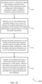
- Process flow 500 may be an example of the use of different autonomous uplink transmission techniques, where UE 115-c may be configured to enable/disable AUL transmissions based on DCI.
- the base station 105-c may determine to enable the UE 115-b to for AUL transmissions. Such a determination may be made, for example, on an amount of information present at the UE 115-c for transmission (e.g., as reported in a buffer status report (BSR)), one or more other UEs that may be configured for AUL transmissions, channel conditions, network traffic conditions, one or more other parameters, or any combination thereof.
- BSR buffer status report
- the base station 105-c may scramble a DCI CRC with a UE identifier that enables AUL transmissions.
- the UE identifier may be a AUL radio network temporary identifier (AUL-RNTI) that enables AUL transmissions from the UE 115-c.
- AUL-RNTI AUL radio network temporary identifier
- a CRC for the DCI may be generated, and then scrambled with the AUL-RNTI. The base station 105-c may then transmit the DCI 520 with scrambled CRC.
- the UE 115-c may receive the DCI and perform an autonomous uplink LBT procedure.
- the UE 115-c may perform a blind decode of the scrambled DCI according, and determine that AUL transmissions have been activated when the blind decode according to the AUL-RNTI scrambled CRC is successful in decoding the CRC of the DCI.
- the DCI may provide semi-persistent scheduling (SPS) for the UE 115-c, which may be used for AUL transmissions. Based on a successful channel contention procedure, the UE 115-c may then transmit AUL transmission 530. The UE 115-c may continue channel contention procedures and AUL transmissions according to the SPS, in some examples.
- SPS semi-persistent scheduling
- the base station 105-c may determine to disable AUL transmissions at the UE 115-c. Such a determination may be made in a similar manner as discussed above for determining to enable AUL transmissions, and be based on one or more of the same parameters.
- the base station 105-c may scramble a DCI CRC with a UE identifier that disables AUL transmissions.
- the DCI CRC may simply be transmitted without scrambling, which may indicate to the UE 115-c that AUL transmission are disabled.
- a different RNTI may optionally be used to scramble the CRC, which may indicate to the UE 115-c that AUL transmissions are disabled.
- the base station 105-c may transmit DCI 545 to the UE 115-c.
- the UE 115-c may receive the DCI 545, and discontinue unscheduled AUL transmissions. In some examples, the UE 115-c may make a determination to discontinue AUL transmissions based on whether the CRC of the DCI is scrambled or not, or based on an identifier used to scramble the CRC.
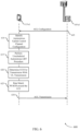
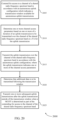
- FIG. 6 illustrates an example of another process flow 600 that supports autonomous uplink transmission techniques using shared radio frequency spectrum in accordance with various aspects of the present disclosure.
- Process flow 600 may include a UE 115-d and base station 105-d, which may be respective examples of a UE 115 and a base station 105 as described herein with reference to FIGs. 1-2 .
- the UE 115-d may identify the AUL configuration and, based on the AUL configuration, may identify that data is to be transmitted to the base station 105-d using one or more AUL transmissions.
- the AUL configuration may include a time period during which the UE 115-d may transmit AUL transmissions, and provide various parameters ( e.g. , MCS, uplink power control parameters, etc. ) .
- the UE 115-d may rate match the UCI and PUSCH information within uplink resources.
- the UE 115-d may embed the A-UCI information by PUSCH rate matching in a similar manner as periodic CSI and ACK/NACK is carried on PUSCH in legacy LTE systems.
- the base station 105-d may signal a number of resources used for rate matching.
- the UCI payload may be a fixed size, and additionally or alternatively may be independent of the actual number of subframes that can be addressed by A-UCI (e.g. payload is budgeted for 4 subframe transmission).
- the UE 115-d may transmit AUL transmission 630 to the base station 105-d.
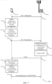
- the UE 115-e may identify the AUL configuration and, based on the AUL configuration, may identify that data is to be transmitted to the base station 105-e using one or more AUL transmissions.
- the AUL configuration may include a time period during which the UE 115-e may transmit AUL transmissions, and provide various parameters ( e.g. , MCS, uplink power control parameters, etc. ) .
- the UE 115-e may perform an LBT procedure in accordance with the AUL configuration.
- the UE 115-e may perform a CCA in order to confirm that a channel of a shared radio frequency spectrum band is unoccupied by another transmitter, in a manner similarly as discussed above.
- the LBT procedure may be successful and the UE 115-e may gain channel access and transmit AUL transmission 720.
- the UE 115-e may perform another LBT procedure in accordance with the AUL configuration. Upon successful LBT and gaining channel access, the UE 115-e may transmit a subsequent AUL transmission 750.
- the AUL transmission 750 may be transmitted according to one or more transmission parameters included in A-DCI 735, and may include an ACK/NACK indication of whether the MAC-CE was successfully received.
- UE autonomous uplink manager 815 and/or at least some of its various sub-components may be implemented in hardware, software executed by a processor, firmware, or any combination thereof. If implemented in software executed by a processor, the functions of the UE autonomous uplink manager 815 and/or at least some of its various sub-components may be executed by a general-purpose processor, a digital signal processor (DSP), an application-specific integrated circuit (ASIC), an field-programmable gate array (FPGA) or other programmable logic device, discrete gate or transistor logic, discrete hardware components, or any combination thereof designed to perform the functions described in the present disclosure.
- DSP digital signal processor
- ASIC application-specific integrated circuit
- FPGA field-programmable gate array
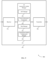
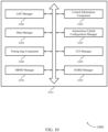
- UE autonomous uplink manager 915 may be an example of aspects of the UE autonomous uplink manager 1115 described with reference to FIG. 11 .
- UE autonomous uplink manager 915 may also include listen-before-talk (LBT) manager 925, control information component 930, data manager 935, and autonomous uplink configuration manager 940.
- LBT listen-before-talk
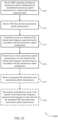
- LBT manager 925 may contend for access to a channel of a shared radio frequency spectrum band in accordance with an autonomous uplink configuration.
- the UAL configuration may indicate a transmission window available for autonomous uplink transmissions and LBT manager 925 may contend for access to a channel of the shared radio frequency spectrum band in accordance with the autonomous uplink configuration.
- control information component 930 may receive A-DCI associated with one or more autonomous uplink transmissions.
- control information may include a CQI or a MCS indicator that is transmitted in a MAC-CE over a shared channel transmission, and an acknowledgment that the CQI or MCS are received may be provided.
- the A-DCI includes a bitmap of feedback information associated with one or more feedback processes associated with one or more autonomous uplink transmission.
- the A-DCI and/or MAC-CE includes uplink power control information for one or more autonomous uplink transmission.
- LBT manager 1020 may contend for access to a channel of a shared radio frequency spectrum band in accordance with an autonomous uplink configuration which indicates a transmission window available for autonomous uplink.
- the control information component 1025 may receive A-DCI associated with one or more autonomous uplink transmissions.
- a CQI or a MCS indicator may be provided in a MAC-CE transmitted over a shared channel, and an acknowledgment that the CQI or MCS are received may be provided.
- the A-DCI includes a bitmap of feedback information associated with one or more feedback processes associated with one or more autonomous uplink transmission.
- the A-DCI and/or MAC-CE includes uplink power control information for one or more autonomous uplink transmission.
- the difference between a MCOT and the duration of the uplink transmission is indicated in the channel access parameters as a number of subframes available for use by one or more other transmitters.
- the DCI includes a CRC field scrambled with an identifier, and a value of the identifier indicates that the DCI is associated with autonomous uplink transmissions.
- the one or more channel access parameters may include a MCOT for the uplink transmission, and a time difference between the MCOT and the duration of the uplink transmission.
- a payload size of uplink control information may be a fixed size configured in the autonomous uplink configuration. In some cases, the payload size is independent of a number of subframes of the uplink transmission. In some cases, the resources used for the uplink control information and rate matching of the shared channel information is configured in the autonomous uplink configuration.
- Data manager 1030 may manage uplink transmissions. In some cases, data manager 1030 may modify a waveform of the uplink transmission based on the TA, and transmit the uplink transmission over a channel of the shared radio frequency spectrum band in accordance with the autonomous uplink configuration, where the uplink transmission indicates one or more of the channel access parameters. In some cases, data manager 1030 may determine that additional data is to be transmitted following a transmission window for AUL transmissions, and transmit one or more subsequent uplink transmissions after the uplink transmission outside of the transmission window when a MCOT is determined as part of the contending for access to the channel of the shared radio frequency spectrum band.
- data manager 1030 may determine that AUL transmissions are activated, transmit one or more autonomous uplink transmissions over the channel of the shared radio frequency spectrum band in accordance with the autonomous uplink configuration, and discontinue contending for access to the channel of the shared radio frequency spectrum band responsive to the receiving a DCI that deactivates autonomous uplink transmissions. In some cases, data manager 1030 may rate match uplink shared channel information around the uplink control information in the uplink transmission.
- Autonomous uplink configuration manager 1035 may receive RRC signaling including an autonomous uplink configuration for unscheduled autonomous uplink transmissions in a shared radio frequency spectrum band and identify an autonomous uplink configuration for unscheduled uplink transmissions in a shared radio frequency spectrum band.
- Timing gap component 1040 may identify a time for starting a subsequent downlink transmission following the uplink transmission, format the uplink transmission to occupy the channel of the shared radio frequency spectrum band until the time for starting the subsequent downlink transmission.
- a transmitter of the subsequent downlink transmission performs a CCA to occupy a maximum time gap between the uplink transmission and the subsequent downlink transmission.
- timing gap component 1040 may transmit a time difference between a MCOT and a duration of the uplink transmission to a base station, where the base station may transmit one or more transmissions during the time difference. In some cases, one or more other UEs may be precluded from transmitting during the time difference.
- a AUL waveform may be modified by formatting data to be transmitted into the uplink transmission, identifying a timing for starting a subsequent downlink transmission following the uplink transmission and a maximum time gap between the uplink transmission and the subsequent downlink transmission, determining a difference between the maximum time gap and the TA, and puncturing a last symbol of the uplink transmission for a duration of the difference between the maximum time gap and the TA.
- the waveform may be modified by formatting data to be transmitted into the uplink transmission, identifying a timing for starting a subsequent downlink transmission following the uplink transmission and a maximum time gap between the uplink transmission and the subsequent downlink transmission, determining a time difference between an end of a last symbol of the uplink transmission and the maximum time gap, and cyclically extending samples of the last symbol of the uplink transmission to extend for a duration of the difference between the maximum time gap and the TA.
- the determining one or more channel access parameters further includes determining that the TA exceeds a maximum time gap between the uplink transmission and a subsequent downlink transmission, and where the TA is indicated in the uplink transmission to allow another transmitter to transmit a reservation signal for at least a portion of the TA.
- UCI manager 1045 may identify UCI associated with the uplink transmission and transmit the UCI in a symbol of the uplink transmission before a last symbol of the uplink transmission.
- a first subframe of a first subsequent uplink transmission of the one or more subsequent uplink transmissions includes control channel information that provides information on the one or more subsequent uplink transmissions.
- UCI may include a burst length of the uplink transmission, a MCOT, a RV indication, a NDI, or an AUL-RNTI.
- MIMO manager 1050 may enable autonomous uplink transmissions on one or more transmit antennas according to a MIMO configuration.
- HARQ manager 1055 may provide one or more of a HARQ identification and provide HARQ processing.
- the HARQ feedback information includes one or more ACK/NACK indications for one or more HARQ processes.
- the bits from two or more feedback processes are bundled.
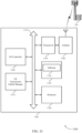
- FIG. 11 shows a diagram of a system 1100 including a device 1105 that supports autonomous uplink transmission techniques using shared radio frequency spectrum in accordance with various aspects of the present disclosure.
- Device 1105 may be an example of or include the components of wireless device 805, wireless device 905, or a UE 115 as described above, e.g., with reference to FIGs. 1 , 8 and 9 .
- Device 1105 may include components for bi-directional voice and data communications including components for transmitting and receiving communications, including UE autonomous uplink manager 1115, processor 1120, memory 1125, software 1130, transceiver 1135, antenna 1140, and I/O controller 1145. These components may be in electronic communication via one or more busses (e.g., bus 1110).
- Device 1105 may communicate wirelessly with one or more base stations 105.
- Processor 1120 may include an intelligent hardware device, (e.g. , a general-purpose processor, a DSP, a central processing unit (CPU), a microcontroller, an ASIC, an FPGA, a programmable logic device, a discrete gate or transistor logic component, a discrete hardware component, or any combination thereof).
- processor 1120 may be configured to operate a memory array using a memory controller.
- a memory controller may be integrated into processor 1120.
- Processor 1120 may be configured to execute computer-readable instructions stored in a memory to perform various functions (e.g ., functions or tasks supporting autonomous uplink transmission techniques using shared radio frequency spectrum).
- Memory 1125 may include random access memory (RAM) and read only memory (ROM).
- RAM random access memory
- ROM read only memory
- the memory 1125 may store computer-readable, computer-executable software 1130 including instructions that, when executed, cause the processor to perform various functions described herein.
- the memory 1125 may contain, among other things, a basic input/output system (BIOS) which may control basic hardware and/or software operation such as the interaction with peripheral components or devices.
- BIOS basic input/output system
- Software 1130 may include code to implement aspects of the present disclosure, including code to support autonomous uplink transmission techniques using shared radio frequency spectrum.
- Software 1130 may be stored in a non-transitory computer-readable medium such as system memory or other memory. In some cases, the software 1130 may not be directly executable by the processor but may cause a computer ( e.g ., when compiled and executed) to perform functions described herein.
- Transceiver 1135 may communicate bi-directionally, via one or more antennas, wired, or wireless links as described above.
- the transceiver 1135 may represent a wireless transceiver and may communicate bi-directionally with another wireless transceiver.
- the transceiver 1135 may also include a modem to modulate the packets and provide the modulated packets to the antennas for transmission, and to demodulate packets received from the antennas.
- the wireless device may include a single antenna 1140. However, in some cases the device may have more than one antenna 1140, which may be capable of concurrently transmitting or receiving multiple wireless transmissions.
- I/O controller 1145 may manage input and output signals for device 1105. I/O controller 1145 may also manage peripherals not integrated into device 1105. In some cases, I/O controller 1145 may represent a physical connection or port to an external peripheral. In some cases, I/O controller 1145 may utilize an operating system such as iOS ® , ANDROID ® , MS-DOS ® , MS-WINDOWS ® , OS/2 ® , UNIX ® , LINUX ® , or another known operating system. In other cases, I/O controller 1145 may represent or interact with a modem, a keyboard, a mouse, a touchscreen, or a similar device. In some cases, I/O controller 1145 may be implemented as part of a processor. In some cases, a user may interact with device 1105 via I/O controller 1145 or via hardware components controlled by I/O controller 1145.
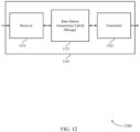
- FIG. 12 shows a block diagram 1200 of a wireless device 1205 that supports autonomous uplink transmission techniques using shared radio frequency spectrum in accordance with various aspects of the present disclosure.
- Wireless device 1205 may be an example of aspects of a base station 105 as described with reference to FIG. 1 .
- Wireless device 1205 may include receiver 1210, base station autonomous uplink manager 1215, and transmitter 1220.
- Wireless device 1205 may also include a processor. Each of these components may be in communication with one another ( e.g ., via one or more buses).
- Receiver 1210 may receive information such as packets, user data, or control information associated with various information channels (e.g ., control channels, data channels, and information related to autonomous uplink transmission techniques using shared radio frequency spectrum, etc. ) . Information may be passed on to other components of the device.
- the receiver 1210 may be an example of aspects of the transceiver 1535 described with reference to FIG. 15 .
- Receiver 1210 may receive one or more autonomous uplink transmissions over the channel of the shared radio frequency spectrum band in accordance with the autonomous uplink configuration.
- Base station autonomous uplink manager 1215 may be an example of aspects of the base station autonomous uplink manager 1515 described with reference to FIG. 15 .
- Base station autonomous uplink manager 1215 and/or at least some of its various sub-components may be implemented in hardware, software executed by a processor, firmware, or any combination thereof. If implemented in software executed by a processor, the functions of the base station autonomous uplink manager 1215 and/or at least some of its various sub-components may be executed by a general-purpose processor, a DSP, an ASIC, an FPGA or other programmable logic device, discrete gate or transistor logic, discrete hardware components, or any combination thereof designed to perform the functions described in the present disclosure.
- the base station autonomous uplink manager 1215 and/or at least some of its various sub-components may be physically located at various positions, including being distributed such that portions of functions are implemented at different physical locations by one or more physical devices.
- base station autonomous uplink manager 1215 and/or at least some of its various sub-components may be a separate and distinct component in accordance with various aspects of the present disclosure.
- base station autonomous uplink manager 1215 and/or at least some of its various sub-components may be combined with one or more other hardware components, including but not limited to an I/O component, a transceiver, a network server, another computing device, one or more other components described in the present disclosure, or a combination thereof in accordance with various aspects of the present disclosure.
- Base station autonomous uplink manager 1215 may configure a UE for autonomous uplink transmissions in a shared radio frequency spectrum band, receive an autonomous uplink transmission from the UE over the shared radio frequency spectrum band, the autonomous uplink transmission including one or more channel access parameters, and transmit a downlink transmission over the shared radio frequency spectrum band in accordance with one or more of the channel access parameters.
- the base station autonomous uplink manager 1215 may also transmit RRC signaling to a UE that includes an autonomous uplink configuration for unscheduled autonomous uplink transmissions in a shared radio frequency spectrum band, determine that the autonomous uplink transmissions should be activated for the UE, transmit DCI that activates autonomous uplink transmissions responsive to determining that the autonomous uplink transmissions should be activated for the UE, determine that that the autonomous uplink transmissions should be deactivated for the UE, and transmit DCI that deactivates the autonomous uplink transmissions responsive to determining that the autonomous uplink transmissions should be deactivated for the UE.
- Transmitter 1220 may transmit signals generated by other components of the device.
- the transmitter 1220 may be collocated with a receiver 1210 in a transceiver module.
- the transmitter 1220 may be an example of aspects of the transceiver 1535 described with reference to FIG. 15 .
- the transmitter 1220 may include a single antenna, or it may include a set of antennas.
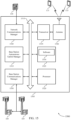
- FIG. 13 shows a block diagram 1300 of a wireless device 1305 that supports autonomous uplink transmission techniques using shared radio frequency spectrum in accordance with various aspects of the present disclosure.
- Wireless device 1305 may be an example of aspects of a wireless device 1205 or a base station 105 as described with reference to FIGs. 1 and 12 .
- Wireless device 1305 may include receiver 1310, base station autonomous uplink manager 1315, and transmitter 1320.
- Wireless device 1305 may also include a processor. Each of these components may be in communication with one another ( e.g. , via one or more buses).
- Receiver 1310 may receive information such as packets, user data, or control information associated with various information channels (e.g ., control channels, data channels, and information related to autonomous uplink transmission techniques using shared radio frequency spectrum, etc. ) . Information may be passed on to other components of the device.
- the receiver 1310 may be an example of aspects of the transceiver 1535 described with reference to FIG. 15 .
- Base station autonomous uplink manager 1315 may be an example of aspects of the base station autonomous uplink manager 1515 described with reference to FIG. 15 .
- Base station autonomous uplink manager 1315 may also include autonomous uplink configuration manager 1325, AUL channel access manager 1330, data manager 1335, AUL activation component 1340, and control information component 1345.
- Autonomous uplink configuration manager 1325 may configure a UE for autonomous uplink transmissions in a shared radio frequency spectrum band and transmit RRC signaling to a UE that includes an autonomous uplink configuration for unscheduled autonomous uplink transmissions in a shared radio frequency spectrum band.
Landscapes
- Engineering & Computer Science (AREA)
- Signal Processing (AREA)
- Computer Networks & Wireless Communication (AREA)
- Quality & Reliability (AREA)
- Mobile Radio Communication Systems (AREA)
Claims (13)
- Ein Verfahren für eine drahtlose Kommunikation durch ein Benutzergerät (User Equipment bzw. UE), aufweisend:Konkurrieren (415) um einen Zugang zu einem Kanal eines gemeinsamen Hochfrequenzspektralbands gemäß einer Autonome-Aufwärtsstrecke-Konfiguration, die ein für autonome Aufwärtsstrecke-Sendungen verfügbares Sendefenster angibt,Erhalten eines Kanalzugangs und Identifizieren einer maximalen Kanalbesetzungszeit (Maximum Channel Occupancy Time bzw. MCOT), die mit autonomen Aufwärtsstrecke-Sendungen assoziiert ist,Bestimmen (420) einer Dauer einer Aufwärtsstrecke-Sendung, die über den Kanal des gemeinsamen Hochfrequenzspektralbands zu senden ist,Bestimmen (425) eines oder mehrerer Kanalzugangsparameter für die Verwendung durch eines oder mehrere andere Sendegeräte, die verschieden von dem UE sind, basierend wenigstens teilweise auf der Dauer der Aufwärtsstrecke-Sendung, wobei das Bestimmen (425) eines oder mehrerer Kanalzugangsparameter das Bestimmen einer Differenz zwischen der MCOT und der Dauer der Aufwärtsstrecke-Sendung aufweist, wobei die Kanalzugangsparameter wenigstens die Differenz zwischen der MCOT und der Dauer der Aufwärtsstrecke-Sendung, die in den Kanalzugangsparametern für die Verwendung durch die eine oder die mehreren anderen Sendegeräte angegeben sind, als eine Anzahl von Subrahmen, die für die Verwendung durch das eine oder die mehreren anderen Sendegeräte verfügbar sind, aufweisen,Senden (430) der Aufwärtsstrecke-Sendung über den Kanal des gemeinsamen Hochfrequenz-Spektralbands gemäß der Autonome-Aufwärtsstrecke-Konfiguration, wobei die Aufwärtsstrecke-Sendung den einen oder die mehreren Kanalzugangsparameter für die Verwendung durch das eine oder die mehreren anderen Sendegeräte einschließlich wenigstens der Differenz zwischen der MCOT und der Dauer der Aufwärtsstrecke-Sendung angibt.
- Verfahren nach Anspruch 1, wobei die autonomen Aufwärtsstrecke (Autonomous Uplink bzw. AUL)-Sendungen ungeplante Aufwärtsstrecke-Sendungen in dem gemeinsamen Hochfrequenzspektralband sind.
- Verfahren nach Anspruch 1, das weiterhin aufweist:Bestimmen des einen oder der mehreren Kanalzugangsparameter für die Verwendung durch das eine oder die mehreren anderen Sendegeräte basierend wenigstens teilweise auf einem Timing-Advance (TA) für die Aufwärtsstrecke-Sendung, undModifizieren einer Wellenform der Aufwärtsstrecke-Sendung basierend wenigstens teilweise auf dem TA.
- Verfahren nach Anspruch 3, wobei das Modifizieren der Wellenform aufweist:Formatieren von zu sendenden Daten zu der Aufwärtsstrecke-Sendung,Identifizieren eines Zeitpunkts für das Starten einer folgenden Abwärtsstrecke-Sendung, die auf die Aufwärtsstrecke-Sendung folgt, und eines maximalen Zeitabstands zwischen der Aufwärtsstrecke-Sendung und der folgenden Abwärtsstrecke-Sendung,Bestimmen einer Differenz zwischen dem maximalen Zeitabstand und dem TA, undPunktieren eines letzten Symbols der Aufwärtsstrecke-Sendung für die Dauer der Differenz zwischen dem maximalen Zeitabstand und dem TA.
- Verfahren nach Anspruch 3, wobei das Modifizieren der Wellenform aufweist:Formatieren von zu sendenden Daten zu der Aufwärtsstrecke-Sendung,Identifizieren eines Zeitpunkts für das Starten einer folgenden Abwärtsstrecke-Sendung, die auf die Aufwärtsstrecke-Sendung folgt, und eines maximalen Zeitabstands zwischen der Aufwärtsstrecke-Sendung und der folgenden Abwärtsstrecke-Sendung,Bestimmen einer Zeitdifferenz zwischen einem Ende eines letzten Symbols der Aufwärtsstrecke-Sendung und dem maximalen Zeitabstand, undzyklisches Erweitern von Proben des letzten Symbols der Aufwärtsstrecke-Sendung für eine Erweiterung für die Dauer der Differenz zwischen dem maximalen Zeitabstand und dem TA.
- Verfahren nach Anspruch 1, wobei das Bestimmen eines oder mehrerer Kanalzugangsparameter weiterhin aufweist:
Bestimmen, dass ein Timing-Advance (TA) für die Aufwärtsstrecke-sendung einen maximalen Zeitabstand zwischen der Aufwärtsstrecke-Sendung und einer folgenden Abwärtsstrecke-Sendung überschreitet, wobei das TA in der Aufwärtsstrecke-Sendung angegeben wird, um zu erlauben, dass ein anderer Sender ein Reservierungssignal für wenigstens einen Teil des TA sendet. - Verfahren nach Anspruch 1, das weiterhin aufweist:Identifizieren von Aufwärtsstrecke-Steuerinformationen (Uplink Control Information bzw. UCI), die mit der Aufwärtsstrecke-Sendung assoziiert sind, undSenden der UCI in einem Symbol der Aufwärtsstrecke-Sendung vor einem letzten Symbol der Aufwärtsstrecke-Sendung.
- Verfahren nach Anspruch 1, das weiterhin aufweist:Identifizieren eines Zeitpunkts für das Starten einer folgenden Abwärtsstrecke-Sendung, die auf die Aufwärtsstrecke-Sendung folgt, undFormatieren der Aufwärtsstrecke-Sendung für ein Einnehmen des Kanals des gemeinsamen Hochfrequenzspektralbands bis zu dem Zeitpunkt für das Starten der folgenden Abwärtsstrecke-Sendung, wobei ein Sender der folgenden Abwärtsstrecke-Sendung eine Freier-Kanal-Bestimmung (Clear Channel Assessment bzw. CCA) für das Einnehmen eines maximalen Zeitabstands zwischen der Aufwärtsstrecke-Sendung und der folgenden Abwärtsstrecke-Sendung durchführt.
- Verfahren nach Anspruch 1, das weiterhin aufweist:
Senden einer Zeitdifferenz zwischen einer maximalen Kanalbesetzungszeit (Maximum Channel Occupancy Time bzw. MCOT) und der Dauer der Aufwärtsstrecke-Sendung an eine Basisstation, wobei die Basisstation eine oder mehrere Sendungen während der Zeitdifferenz senden kann oder ein Senden durch einen oder mehrere andere Sender während der Zeitdifferenz ausgeschlossen wird. - Verfahren nach Anspruch 1, das weiterhin aufweist:Bestimmen, dass zusätzliche Daten auf das Sendefenster folgend zu senden sind, undSenden einer oder mehrerer folgender Aufwärtsstrecke-Sendungen nach der Aufwärtsstrecke-Sendung außerhalb des Sendefensters, wenn eine maximale Kanalbesetzungszeit (Maximum Channel Occupancy Time bzw. MCOT) als Teil des Konkurrierens um einen Zugang zu dem Kanal des gemeinsamen Hochfrequenzspektralbands bestimmt wird.
- Verfahren nach Anspruch 10, wobei ein erster Subrahmen einer ersten folgenden Aufwärtsstrecke-Sendung der einen oder der mehreren folgenden Aufwärtsstrecke-Sendungen Steuerkanalinformationen enthält, die Informationen zu der einen oder den mehreren folgenden Aufwärtsstrecke-Sendungen vorsehen.
- Ein Benutzergerät (User Equipment bzw. UE), das Mittel zum Ausführen aller Verfahrensschritte der Ansprüche 1 bis 11 aufweist.
- Ein nicht-transitorisches, computerlesbares Medium, das einen computerausführbaren Code speichert, der bei einer Ausführung durch einen Prozessor das Verfahren gemäß einem der Ansprüche 1 bis 11 ausführt.
Priority Applications (1)
| Application Number | Priority Date | Filing Date | Title |
|---|---|---|---|
| EP25173517.1A EP4576915A1 (de) | 2017-02-06 | 2018-02-05 | Autonome uplink-übertragungstechniken mit gemeinsamem funkfrequenzspektrum |
Applications Claiming Priority (3)
| Application Number | Priority Date | Filing Date | Title |
|---|---|---|---|
| US201762455469P | 2017-02-06 | 2017-02-06 | |
| US15/887,277 US10772113B2 (en) | 2017-02-06 | 2018-02-02 | Autonomous uplink transmission techniques using shared radio frequency spectrum |
| PCT/US2018/016807 WO2018144976A2 (en) | 2017-02-06 | 2018-02-05 | Autonomous uplink transmission techniques using shared radio frequency spectrum |
Related Child Applications (2)
| Application Number | Title | Priority Date | Filing Date |
|---|---|---|---|
| EP25173517.1A Division-Into EP4576915A1 (de) | 2017-02-06 | 2018-02-05 | Autonome uplink-übertragungstechniken mit gemeinsamem funkfrequenzspektrum |
| EP25173517.1A Division EP4576915A1 (de) | 2017-02-06 | 2018-02-05 | Autonome uplink-übertragungstechniken mit gemeinsamem funkfrequenzspektrum |
Publications (3)
| Publication Number | Publication Date |
|---|---|
| EP3577997A2 EP3577997A2 (de) | 2019-12-11 |
| EP3577997B1 true EP3577997B1 (de) | 2025-07-02 |
| EP3577997C0 EP3577997C0 (de) | 2025-07-02 |
Family
ID=63038192
Family Applications (2)
| Application Number | Title | Priority Date | Filing Date |
|---|---|---|---|
| EP18706596.6A Active EP3577997B1 (de) | 2017-02-06 | 2018-02-05 | Autonome uplink-übertragungstechniken mit gemeinsamem hochfrequenzspektrum |
| EP25173517.1A Pending EP4576915A1 (de) | 2017-02-06 | 2018-02-05 | Autonome uplink-übertragungstechniken mit gemeinsamem funkfrequenzspektrum |
Family Applications After (1)
| Application Number | Title | Priority Date | Filing Date |
|---|---|---|---|
| EP25173517.1A Pending EP4576915A1 (de) | 2017-02-06 | 2018-02-05 | Autonome uplink-übertragungstechniken mit gemeinsamem funkfrequenzspektrum |
Country Status (5)
| Country | Link |
|---|---|
| US (3) | US10772113B2 (de) |
| EP (2) | EP3577997B1 (de) |
| CN (2) | CN110249701B (de) |
| TW (1) | TWI758405B (de) |
| WO (1) | WO2018144976A2 (de) |
Families Citing this family (79)
| Publication number | Priority date | Publication date | Assignee | Title |
|---|---|---|---|---|
| US10517021B2 (en) | 2016-06-30 | 2019-12-24 | Evolve Cellular Inc. | Long term evolution-primary WiFi (LTE-PW) |
| CN116015567B (zh) | 2016-08-10 | 2025-03-11 | 交互数字专利控股公司 | 降低等待时间的系统中的定时提前和处理能力 |
| WO2018059311A1 (en) * | 2016-09-30 | 2018-04-05 | Qualcomm Incorporated | Multefire autonomous uplink channel clearance signaling |
| US10772113B2 (en) | 2017-02-06 | 2020-09-08 | Qualcomm Incorporated | Autonomous uplink transmission techniques using shared radio frequency spectrum |
| WO2018174613A1 (en) | 2017-03-24 | 2018-09-27 | Samsung Electronics Co., Ltd. | Method for wireless communication and user equipment |
| MX2019011203A (es) * | 2017-03-24 | 2019-11-05 | Ericsson Telefon Ab L M | Retroalimentacion de harq-ack de enlace ascendente para mtc. |
| WO2018173004A1 (en) * | 2017-03-24 | 2018-09-27 | Telefonaktiebolaget L M Ericsson (Publ) | Multiple starting and ending positions for scheduled downlink transmission on unlicensed spectrum |
| US11310813B2 (en) * | 2017-03-31 | 2022-04-19 | Apple Inc. | Maximum channel occupancy time sharing and co-existence |
| US11483810B2 (en) * | 2017-04-03 | 2022-10-25 | Huawei Technologies Co., Ltd. | Methods and systems for resource configuration of wireless communication systems |
| US20210144757A1 (en) | 2017-06-23 | 2021-05-13 | Idac Holdings, Inc. | Transmission with restrictions in unlicensed spectrum |
| US11140705B2 (en) * | 2017-07-14 | 2021-10-05 | Apple Inc. | Configuration of grant-less uplink transmissions for a user equipment |
| CN109309923A (zh) * | 2017-07-26 | 2019-02-05 | 索尼公司 | 电子装置、信息处理设备和信息处理方法 |
| JP6915064B2 (ja) | 2017-08-04 | 2021-08-04 | エルジー エレクトロニクス インコーポレイティド | 非免許帯域を支援する無線通信システムにおいて端末が上りリンク信号を送信する方法及びそれを支援する装置 |
| AU2018315141B2 (en) * | 2017-08-11 | 2021-10-21 | Telefonaktiebolaget Lm Ericsson (Publ) | Autonomous transmission of uplink control information |
| US10536859B2 (en) | 2017-08-15 | 2020-01-14 | Charter Communications Operating, Llc | Methods and apparatus for dynamic control and utilization of quasi-licensed wireless spectrum |
| US11051175B2 (en) | 2017-08-18 | 2021-06-29 | Qualcomm Incorporated | Uplink transmission techniques in shared spectrum wireless communications |
| EP3673705A1 (de) | 2017-08-22 | 2020-07-01 | Telefonaktiebolaget LM Ericsson (publ) | Steuerung von autonomen ul-übertragungen bei koexistenz mit geplanten ues |
| US10362593B2 (en) * | 2017-09-01 | 2019-07-23 | Huawei Technologies Co., Ltd. | Grant-free uplink transmission in unlicensed spectrum |
| WO2019056370A1 (zh) * | 2017-09-25 | 2019-03-28 | 华为技术有限公司 | 一种通信方法和装置 |
| WO2019097301A1 (en) * | 2017-11-16 | 2019-05-23 | Lenovo (Singapore) Pte. Ltd. | Determining transport block generation timing of an uplink transmission |
| JP7002657B2 (ja) * | 2017-12-28 | 2022-01-20 | 北京小米移動軟件有限公司 | 伝送方向情報を確定する方法及び装置 |
| US11212051B2 (en) * | 2018-03-06 | 2021-12-28 | Qualcomm Incorporated | Beam management for autonomous uplink with analog beams |
| CN110366248B (zh) * | 2018-04-04 | 2024-04-30 | 中兴通讯股份有限公司 | 上行传输、通信方法、装置及基站、终端、存储介质 |
| CN110475353B (zh) * | 2018-05-11 | 2022-06-28 | 华为技术有限公司 | 链路恢复的方法和装置 |
| US11129196B2 (en) * | 2018-05-11 | 2021-09-21 | Qualcomm Incorporated | Shared channel design around reserved resources |
| US20210298007A1 (en) * | 2018-07-06 | 2021-09-23 | Nec Corporation | Methods, devices and computer readable media for aul transmission and reception |
| MX2021001873A (es) | 2018-08-17 | 2021-04-19 | Guangdong Oppo Mobile Telecommunications Corp Ltd | Metodo de transmision de se?al, dispositivo terminal y dispositivo de red. |
| WO2020047020A1 (en) * | 2018-08-28 | 2020-03-05 | Intel Corporation | Apparatus and method for multefire industry release (mfir) |
| KR102385929B1 (ko) * | 2018-09-07 | 2022-04-14 | 주식회사 케이티 | 비면허 대역에서 무선 통신을 수행하는 방법 및 장치 |
| JP7381588B2 (ja) * | 2018-09-14 | 2023-11-15 | オッポ広東移動通信有限公司 | リソース決定及び設定方法、装置、端末、ネットワーク装置 |
| GB2577506A (en) * | 2018-09-26 | 2020-04-01 | Tcl Communication Ltd | Transmission medium sharing in a wireless communications network |
| EP3629662A1 (de) * | 2018-09-27 | 2020-04-01 | Panasonic Intellectual Property Corporation of America | Benutzergerät und basisstation mit übertragung von uplink-steuerdaten |
| US11711842B2 (en) * | 2018-11-02 | 2023-07-25 | Qualcomm Incorporated | Aggregation factor associations in uplink and downlink transmissions |
| US10659112B1 (en) | 2018-11-05 | 2020-05-19 | XCOM Labs, Inc. | User equipment assisted multiple-input multiple-output downlink configuration |
| US10812216B2 (en) | 2018-11-05 | 2020-10-20 | XCOM Labs, Inc. | Cooperative multiple-input multiple-output downlink scheduling |
| US10432272B1 (en) | 2018-11-05 | 2019-10-01 | XCOM Labs, Inc. | Variable multiple-input multiple-output downlink user equipment |
| US10756860B2 (en) | 2018-11-05 | 2020-08-25 | XCOM Labs, Inc. | Distributed multiple-input multiple-output downlink configuration |
| KR20210087089A (ko) | 2018-11-27 | 2021-07-09 | 엑스콤 랩스 인코퍼레이티드 | 넌-코히어런트 협력 다중 입출력 통신 |
| EP3892047A4 (de) * | 2018-12-03 | 2022-08-03 | Telefonaktiebolaget LM Ericsson (publ.) | Uplink-übertragung unter verwendung eines unlizenzierten frequenzspektrums |
| CN111294972B (zh) * | 2018-12-10 | 2021-12-24 | 上海朗帛通信技术有限公司 | 一种被用于无线通信的用户设备、基站中的方法和装置 |
| US10756795B2 (en) | 2018-12-18 | 2020-08-25 | XCOM Labs, Inc. | User equipment with cellular link and peer-to-peer link |
| US11063645B2 (en) | 2018-12-18 | 2021-07-13 | XCOM Labs, Inc. | Methods of wirelessly communicating with a group of devices |
| US11330612B2 (en) * | 2019-01-14 | 2022-05-10 | Qualcomm Incorporated | Autonomous uplink for wideband new radio-unlicensed |
| US11330649B2 (en) | 2019-01-25 | 2022-05-10 | XCOM Labs, Inc. | Methods and systems of multi-link peer-to-peer communications |
| US10756767B1 (en) | 2019-02-05 | 2020-08-25 | XCOM Labs, Inc. | User equipment for wirelessly communicating cellular signal with another user equipment |
| US11388604B2 (en) * | 2019-02-07 | 2022-07-12 | Qualcomm Incorporated | Methods and apparatus for an autonomous downlink transmission |
| CN111107637B (zh) * | 2019-03-25 | 2022-04-01 | 维沃移动通信有限公司 | 共享信道占用时间的方法和设备 |
| US11516842B2 (en) | 2019-03-27 | 2022-11-29 | Qualcomm Incorporated | Channel occupancy time (COT) structure indication |
| US11032841B2 (en) | 2019-04-26 | 2021-06-08 | XCOM Labs, Inc. | Downlink active set management for multiple-input multiple-output communications |
| US10756782B1 (en) | 2019-04-26 | 2020-08-25 | XCOM Labs, Inc. | Uplink active set management for multiple-input multiple-output communications |
| US10686502B1 (en) | 2019-04-29 | 2020-06-16 | XCOM Labs, Inc. | Downlink user equipment selection |
| US10735057B1 (en) | 2019-04-29 | 2020-08-04 | XCOM Labs, Inc. | Uplink user equipment selection |
| US11457474B2 (en) | 2019-05-02 | 2022-09-27 | Apple, Inc. | Channel sensing indication when COT sharing in NR systems operating in unlicensed spectrum |
| US11438771B2 (en) | 2019-07-11 | 2022-09-06 | Charter Communications Operating, Llc | Apparatus and methods for heterogeneous coverage and use cases in a quasi-licensed wireless system |
| US11411778B2 (en) | 2019-07-12 | 2022-08-09 | XCOM Labs, Inc. | Time-division duplex multiple input multiple output calibration |
| US11849481B2 (en) * | 2019-08-08 | 2023-12-19 | Qualcomm Incorporated | Techniques for configuring multiple-SCS and multi-beam direction communications |
| US20220272754A1 (en) * | 2019-08-09 | 2022-08-25 | Lenovo (Beijing) Limited | Method and Apparatus for Sharing Channel Occupancy Time |
| CN114208079B (zh) * | 2019-08-15 | 2024-05-07 | 富士通株式会社 | 数据传输的方法及其装置、通信系统 |
| US11606811B2 (en) * | 2019-08-26 | 2023-03-14 | Qualcomm Incorporated | Techniques for determining resources for communicating over an acquired channel |
| US11026205B2 (en) * | 2019-10-23 | 2021-06-01 | Charter Communications Operating, Llc | Methods and apparatus for device registration in a quasi-licensed wireless system |
| EP4021135A4 (de) | 2019-11-04 | 2022-08-10 | Guangdong Oppo Mobile Telecommunications Corp., Ltd. | Verfahren zur verwendung der belegungszeit eines gemeinsam genutzten listen-before-talk-kanals kategorie 1 und zugehörige vorrichtung |
| PH12022550970A1 (en) | 2019-11-08 | 2023-09-25 | Qualcomm Inc | Configured grant channel occupancy time sharing procedure |
| EP4025001B1 (de) * | 2019-12-31 | 2025-02-26 | Guangdong Oppo Mobile Telecommunications Corp., Ltd. | Drahtloskommunikationsverfahren und vorrichtung sowie kommunikationsvorrichtung |
| WO2021189340A1 (en) | 2020-03-26 | 2021-09-30 | Qualcomm Incorporated | Continuous transmission for new radio-unlicensed (nr-u) uplink |
| WO2021189499A1 (zh) * | 2020-03-27 | 2021-09-30 | 华为技术有限公司 | 通信方法及相关产品 |
| US11411779B2 (en) | 2020-03-31 | 2022-08-09 | XCOM Labs, Inc. | Reference signal channel estimation |
| BR112022020191A2 (pt) * | 2020-04-10 | 2022-11-22 | Nokia Technologies Oy | Ajuste para avanço de tempo |
| US12088499B2 (en) | 2020-04-15 | 2024-09-10 | Virewirx, Inc. | System and method for reducing data packet processing false alarms |
| KR20230015932A (ko) | 2020-05-26 | 2023-01-31 | 엑스콤 랩스 인코퍼레이티드 | 간섭-인식 빔포밍 |
| US11611991B2 (en) * | 2020-09-02 | 2023-03-21 | Qualcomm Incorporated | Frequency resource reservation for sidelink communication |
| WO2022047750A1 (zh) * | 2020-09-04 | 2022-03-10 | Oppo广东移动通信有限公司 | Lbt参数的确定方法、装置、设备及介质 |
| CA3195885A1 (en) | 2020-10-19 | 2022-04-28 | XCOM Labs, Inc. | Reference signal for wireless communication systems |
| WO2022093988A1 (en) | 2020-10-30 | 2022-05-05 | XCOM Labs, Inc. | Clustering and/or rate selection in multiple-input multiple-output communication systems |
| US11564104B2 (en) | 2020-11-25 | 2023-01-24 | Charter Communications Operating, Llc | Apparatus and methods for spectrum scheduling in heterogeneous wireless networks |
| US11716732B2 (en) * | 2020-12-09 | 2023-08-01 | Qualcomm Incorporated | Feedback configuration for uplink control messages |
| CN116648867A (zh) | 2020-12-16 | 2023-08-25 | 艾斯康实验室公司 | 具有准全向波束和定向波束的无线通信 |
| WO2022241436A1 (en) | 2021-05-14 | 2022-11-17 | XCOM Labs, Inc. | Scrambling identifiers for wireless communication systems |
| CN116133147A (zh) * | 2021-11-12 | 2023-05-16 | 华为技术有限公司 | 数据传输方法及装置、存储介质、程序产品 |
| GB2643728A (en) * | 2024-08-29 | 2026-03-04 | Nokia Technologies Oy | Handling transmission on shared resource |
Citations (1)
| Publication number | Priority date | Publication date | Assignee | Title |
|---|---|---|---|---|
| EP3529930B1 (de) * | 2016-10-21 | 2021-12-08 | Telefonaktiebolaget LM Ericsson (publ) | Harq-feedback für ungeplantes uplink |
Family Cites Families (31)
| Publication number | Priority date | Publication date | Assignee | Title |
|---|---|---|---|---|
| CN101166055B (zh) * | 2006-10-18 | 2011-06-01 | 华为技术有限公司 | 多跳中继方法和多跳中继系统 |
| US20100271970A1 (en) * | 2009-04-22 | 2010-10-28 | Interdigital Patent Holdings, Inc. | Method and apparatus for transmitting uplink control information for carrier aggregated spectrums |
| CN102892206B (zh) * | 2011-07-20 | 2014-12-31 | 上海交通大学 | 认知无线传感器网络中基于网络特性的单天线mac传输方法 |
| CN102932947B (zh) * | 2011-08-12 | 2016-03-30 | 上海贝尔股份有限公司 | 用于控制用户设备在从小区上的自主的上行传输的方法 |
| US9094999B2 (en) * | 2012-04-02 | 2015-07-28 | Intel Deutschland Gmbh | Radio communication device and method for operating a radio communication device |
| US9717071B2 (en) * | 2013-08-16 | 2017-07-25 | Qualcomm Incorporated | Uplink procedures for LTE/LTE-A communication systems with unlicensed spectrum |
| US9491752B2 (en) * | 2014-02-24 | 2016-11-08 | Qualcomm Incorporated | Techniques for enabling asynchronous time division duplexing transmissions in an unlicensed radio frequency spectrum band |
| CN105101388B (zh) * | 2014-05-08 | 2019-08-23 | 上海诺基亚贝尔股份有限公司 | 在新配置参数的使用上同步UE和SeNB的方法和装置 |
| US10194424B2 (en) * | 2014-05-20 | 2019-01-29 | Qualcomm Incorporated | Techniques for managing resources for uplink transmissions in a shared radio frequency spectrum band |
| US9867187B2 (en) * | 2014-08-04 | 2018-01-09 | Qualcomm Incorporated | Techniques for configuring uplink channel transmissions using shared radio frequency spectrum band |
| US11057921B2 (en) | 2014-10-01 | 2021-07-06 | Samsung Electronics Co., Ltd. | System and method for improving spectral efficiency and coverage for user equipments |
| US9872313B2 (en) | 2014-10-02 | 2018-01-16 | Qualcomm Incorporated | Contention based uplink transmissions for latency reduction |
| US10637619B2 (en) * | 2014-11-03 | 2020-04-28 | Samsung Electronics Co., Ltd. | Method and apparatus for channel access for LTE on unlicensed spectrum |
| EP3217702A4 (de) * | 2014-11-07 | 2017-11-01 | Ntt Docomo, Inc. | Benutzervorrichtung, basisstation und uplink-trägeraggregationskommunikationsverfahren |
| US10772021B2 (en) * | 2014-12-05 | 2020-09-08 | Qualcomm Incorporated | Low latency and/or enhanced component carrier discovery for services and handover |
| CN107409370B (zh) * | 2014-12-23 | 2020-08-21 | Idac控股公司 | 通过wtru执行的用于传达数据的方法及wtru |
| EP3240346B1 (de) * | 2014-12-25 | 2021-09-01 | Nec Corporation | Drahtloses endgerät, drahtlose station und davon ausgeführten verfahren, programm und system |
| KR102586204B1 (ko) * | 2015-01-30 | 2023-10-10 | 한국전자통신연구원 | 비면허 대역을 이용한 셀룰러 시스템의 신호 송신 방법 및 장치 |
| US10524236B2 (en) * | 2015-03-23 | 2019-12-31 | Qualcomm Incorporated | Uplink transmission control with clear channel assessment |
| EP3275256B1 (de) * | 2015-03-23 | 2019-06-05 | Telefonaktiebolaget LM Ericsson (publ) | Selektive verwendung von geplanten und ungeplanten übertragungen für offload eines mobilfunknetzes |
| US20160295624A1 (en) * | 2015-04-02 | 2016-10-06 | Samsung Electronics Co., Ltd | Methods and apparatus for resource pool design for vehicular communications |
| US10159089B2 (en) | 2015-04-20 | 2018-12-18 | Qualcomm Incorporated | Uplink listen before talk operation |
| US10477527B2 (en) * | 2015-07-14 | 2019-11-12 | Qualcomm Incorporated | Semi-persistent scheduling mechanisms for vehicle-to-vehicle communication |
| CN106658742B (zh) * | 2015-11-03 | 2020-07-03 | 中兴通讯股份有限公司 | 数据调度及传输的方法、装置及系统 |
| JP6822418B2 (ja) * | 2016-01-25 | 2021-01-27 | 日本電気株式会社 | ネットワーク装置、無線端末、及びこれらの方法 |
| AU2016390529B2 (en) * | 2016-01-29 | 2020-11-26 | Panasonic Intellectual Property Corporation Of America | eNodeB, user equipment and wireless communication method |
| US10812982B2 (en) | 2016-02-05 | 2020-10-20 | Qualcomm Incorporated | Autonomous uplink transmission in unlicensed spectrum |
| CN116347614B (zh) * | 2016-04-01 | 2025-11-04 | 松下电器(美国)知识产权公司 | 车辆移动装置和无线电基站 |
| EP3451774B1 (de) * | 2016-05-13 | 2020-11-04 | Huawei Technologies Co., Ltd. | Dienstdatenübertragungsverfahren und benutzergerät |
| US11109400B2 (en) * | 2016-10-17 | 2021-08-31 | Qualcomm Incorporated | Semi-autonomous transmissions |
| US10772113B2 (en) | 2017-02-06 | 2020-09-08 | Qualcomm Incorporated | Autonomous uplink transmission techniques using shared radio frequency spectrum |
-
2018
- 2018-02-02 US US15/887,277 patent/US10772113B2/en active Active
- 2018-02-05 CN CN201880010061.2A patent/CN110249701B/zh active Active
- 2018-02-05 CN CN202310091924.6A patent/CN116074978B/zh active Active
- 2018-02-05 EP EP18706596.6A patent/EP3577997B1/de active Active
- 2018-02-05 EP EP25173517.1A patent/EP4576915A1/de active Pending
- 2018-02-05 TW TW107103959A patent/TWI758405B/zh active
- 2018-02-05 WO PCT/US2018/016807 patent/WO2018144976A2/en not_active Ceased
-
2020
- 2020-08-07 US US16/988,543 patent/US11647496B2/en active Active
-
2023
- 2023-04-03 US US18/194,962 patent/US12200683B2/en active Active
Patent Citations (1)
| Publication number | Priority date | Publication date | Assignee | Title |
|---|---|---|---|---|
| EP3529930B1 (de) * | 2016-10-21 | 2021-12-08 | Telefonaktiebolaget LM Ericsson (publ) | Harq-feedback für ungeplantes uplink |
Also Published As
| Publication number | Publication date |
|---|---|
| US11647496B2 (en) | 2023-05-09 |
| US20230345453A1 (en) | 2023-10-26 |
| TW201836375A (zh) | 2018-10-01 |
| EP3577997A2 (de) | 2019-12-11 |
| US20180227936A1 (en) | 2018-08-09 |
| CN110249701A (zh) | 2019-09-17 |
| CN110249701B (zh) | 2023-03-24 |
| CN116074978A (zh) | 2023-05-05 |
| EP4576915A1 (de) | 2025-06-25 |
| WO2018144976A2 (en) | 2018-08-09 |
| WO2018144976A3 (en) | 2018-10-04 |
| CN116074978B (zh) | 2025-11-11 |
| TWI758405B (zh) | 2022-03-21 |
| US12200683B2 (en) | 2025-01-14 |
| US20200374897A1 (en) | 2020-11-26 |
| US10772113B2 (en) | 2020-09-08 |
| EP3577997C0 (de) | 2025-07-02 |
Similar Documents
| Publication | Publication Date | Title |
|---|---|---|
| US12200683B2 (en) | Autonomous uplink transmission techniques using shared radio frequency spectrum | |
| EP3552445B1 (de) | Steuerkanalkonfiguration und taktung für autonome aufwärtsstrecke | |
| EP3412106B1 (de) | Autonome aufwärtsstreckenübertragung in einem unlizenzierten frequenzspektrum | |
| CA3051127C (en) | Signaling for multiplexing of low latency communication and sidelink communications | |
| EP3556153B1 (de) | Leistungsadaptive sidelink-datenübertragungen | |
| EP4247093A2 (de) | Periodische berechtigungen für zeitintervallkonfigurationen für mehrere übertragungen | |
| WO2018175051A1 (en) | Cross-carrier scheduling for wireless devices | |
| WO2018175519A1 (en) | Partial subframe transmission techniques in shared radio frequency spectrum | |
| EP3577817B1 (de) | Rückkopplungstaktungsverwaltung für kommunikation mit niedriger latenz | |
| WO2018059528A1 (en) | Autonomous uplink in multefire | |
| WO2018058527A1 (en) | Autonomous uplink benefit identification |
Legal Events
| Date | Code | Title | Description |
|---|---|---|---|
| STAA | Information on the status of an ep patent application or granted ep patent |
Free format text: STATUS: UNKNOWN |
|
| STAA | Information on the status of an ep patent application or granted ep patent |
Free format text: STATUS: THE INTERNATIONAL PUBLICATION HAS BEEN MADE |
|
| PUAI | Public reference made under article 153(3) epc to a published international application that has entered the european phase |
Free format text: ORIGINAL CODE: 0009012 |
|
| STAA | Information on the status of an ep patent application or granted ep patent |
Free format text: STATUS: REQUEST FOR EXAMINATION WAS MADE |
|
| 17P | Request for examination filed |
Effective date: 20190628 |
|
| AK | Designated contracting states |
Kind code of ref document: A2 Designated state(s): AL AT BE BG CH CY CZ DE DK EE ES FI FR GB GR HR HU IE IS IT LI LT LU LV MC MK MT NL NO PL PT RO RS SE SI SK SM TR |
|
| AX | Request for extension of the european patent |
Extension state: BA ME |
|
| DAV | Request for validation of the european patent (deleted) | ||
| DAX | Request for extension of the european patent (deleted) | ||
| STAA | Information on the status of an ep patent application or granted ep patent |
Free format text: STATUS: EXAMINATION IS IN PROGRESS |
|
| 17Q | First examination report despatched |
Effective date: 20210112 |
|
| REG | Reference to a national code |
Ref country code: DE Ref legal event code: R079 Ref country code: DE Ref legal event code: R079 Ref document number: 602018083150 Country of ref document: DE Free format text: PREVIOUS MAIN CLASS: H04W0074080000 Ipc: H04W0074081600 |
|
| GRAP | Despatch of communication of intention to grant a patent |
Free format text: ORIGINAL CODE: EPIDOSNIGR1 |
|
| STAA | Information on the status of an ep patent application or granted ep patent |
Free format text: STATUS: GRANT OF PATENT IS INTENDED |
|
| RIC1 | Information provided on ipc code assigned before grant |
Ipc: H04W 74/0808 20240101ALN20250129BHEP Ipc: H04L 1/1812 20230101ALI20250129BHEP Ipc: H04L 1/1822 20230101ALI20250129BHEP Ipc: H04L 1/1607 20230101ALI20250129BHEP Ipc: H04L 1/00 20060101ALI20250129BHEP Ipc: H04L 5/00 20060101ALI20250129BHEP Ipc: H04W 72/23 20230101ALI20250129BHEP Ipc: H04W 74/00 20090101ALI20250129BHEP Ipc: H04W 74/0816 20240101AFI20250129BHEP |
|
| INTG | Intention to grant announced |
Effective date: 20250206 |
|
| GRAS | Grant fee paid |
Free format text: ORIGINAL CODE: EPIDOSNIGR3 |
|
| GRAA | (expected) grant |
Free format text: ORIGINAL CODE: 0009210 |
|
| STAA | Information on the status of an ep patent application or granted ep patent |
Free format text: STATUS: THE PATENT HAS BEEN GRANTED |
|
| AK | Designated contracting states |
Kind code of ref document: B1 Designated state(s): AL AT BE BG CH CY CZ DE DK EE ES FI FR GB GR HR HU IE IS IT LI LT LU LV MC MK MT NL NO PL PT RO RS SE SI SK SM TR |
|
| REG | Reference to a national code |
Ref country code: GB Ref legal event code: FG4D |
|
| REG | Reference to a national code |
Ref country code: CH Ref legal event code: EP |
|
| REG | Reference to a national code |
Ref country code: DE Ref legal event code: R096 Ref document number: 602018083150 Country of ref document: DE |
|
| REG | Reference to a national code |
Ref country code: IE Ref legal event code: FG4D |
|
| U01 | Request for unitary effect filed |
Effective date: 20250716 |
|
| U07 | Unitary effect registered |
Designated state(s): AT BE BG DE DK EE FI FR IT LT LU LV MT NL PT RO SE SI Effective date: 20250723 |
|
| PG25 | Lapsed in a contracting state [announced via postgrant information from national office to epo] |
Ref country code: IS Free format text: LAPSE BECAUSE OF FAILURE TO SUBMIT A TRANSLATION OF THE DESCRIPTION OR TO PAY THE FEE WITHIN THE PRESCRIBED TIME-LIMIT Effective date: 20251102 |
|
| PG25 | Lapsed in a contracting state [announced via postgrant information from national office to epo] |
Ref country code: NO Free format text: LAPSE BECAUSE OF FAILURE TO SUBMIT A TRANSLATION OF THE DESCRIPTION OR TO PAY THE FEE WITHIN THE PRESCRIBED TIME-LIMIT Effective date: 20251002 |
|
| PG25 | Lapsed in a contracting state [announced via postgrant information from national office to epo] |
Ref country code: HR Free format text: LAPSE BECAUSE OF FAILURE TO SUBMIT A TRANSLATION OF THE DESCRIPTION OR TO PAY THE FEE WITHIN THE PRESCRIBED TIME-LIMIT Effective date: 20250702 |
|
| PG25 | Lapsed in a contracting state [announced via postgrant information from national office to epo] |
Ref country code: GR Free format text: LAPSE BECAUSE OF FAILURE TO SUBMIT A TRANSLATION OF THE DESCRIPTION OR TO PAY THE FEE WITHIN THE PRESCRIBED TIME-LIMIT Effective date: 20251003 |
|
| PG25 | Lapsed in a contracting state [announced via postgrant information from national office to epo] |
Ref country code: CZ Free format text: LAPSE BECAUSE OF FAILURE TO SUBMIT A TRANSLATION OF THE DESCRIPTION OR TO PAY THE FEE WITHIN THE PRESCRIBED TIME-LIMIT Effective date: 20250702 |
|
| PG25 | Lapsed in a contracting state [announced via postgrant information from national office to epo] |
Ref country code: PL Free format text: LAPSE BECAUSE OF FAILURE TO SUBMIT A TRANSLATION OF THE DESCRIPTION OR TO PAY THE FEE WITHIN THE PRESCRIBED TIME-LIMIT Effective date: 20250702 |
|
| PG25 | Lapsed in a contracting state [announced via postgrant information from national office to epo] |
Ref country code: RS Free format text: LAPSE BECAUSE OF FAILURE TO SUBMIT A TRANSLATION OF THE DESCRIPTION OR TO PAY THE FEE WITHIN THE PRESCRIBED TIME-LIMIT Effective date: 20251002 |
|
| PG25 | Lapsed in a contracting state [announced via postgrant information from national office to epo] |
Ref country code: ES Free format text: LAPSE BECAUSE OF FAILURE TO SUBMIT A TRANSLATION OF THE DESCRIPTION OR TO PAY THE FEE WITHIN THE PRESCRIBED TIME-LIMIT Effective date: 20250702 |
|
| U20 | Renewal fee for the european patent with unitary effect paid |
Year of fee payment: 9 Effective date: 20260112 |
|
| PG25 | Lapsed in a contracting state [announced via postgrant information from national office to epo] |
Ref country code: SM Free format text: LAPSE BECAUSE OF FAILURE TO SUBMIT A TRANSLATION OF THE DESCRIPTION OR TO PAY THE FEE WITHIN THE PRESCRIBED TIME-LIMIT Effective date: 20250702 |
|
| PGFP | Annual fee paid to national office [announced via postgrant information from national office to epo] |
Ref country code: GB Payment date: 20260113 Year of fee payment: 9 |
|
| PGFP | Annual fee paid to national office [announced via postgrant information from national office to epo] |
Ref country code: IE Payment date: 20260109 Year of fee payment: 9 |
|
| PG25 | Lapsed in a contracting state [announced via postgrant information from national office to epo] |
Ref country code: SK Free format text: LAPSE BECAUSE OF FAILURE TO SUBMIT A TRANSLATION OF THE DESCRIPTION OR TO PAY THE FEE WITHIN THE PRESCRIBED TIME-LIMIT Effective date: 20250702 |