EP3578048A1 - Four à cuire à passage continu pour le mode de cuisson continu - Google Patents
Four à cuire à passage continu pour le mode de cuisson continu Download PDFInfo
- Publication number
- EP3578048A1 EP3578048A1 EP19176659.1A EP19176659A EP3578048A1 EP 3578048 A1 EP3578048 A1 EP 3578048A1 EP 19176659 A EP19176659 A EP 19176659A EP 3578048 A1 EP3578048 A1 EP 3578048A1
- Authority
- EP
- European Patent Office
- Prior art keywords
- oven
- baking
- modules
- continuous
- fan
- Prior art date
- Legal status (The legal status is an assumption and is not a legal conclusion. Google has not performed a legal analysis and makes no representation as to the accuracy of the status listed.)
- Granted
Links
Images


Classifications
-
- A—HUMAN NECESSITIES
- A21—BAKING; EDIBLE DOUGHS
- A21B—BAKERS' OVENS; MACHINES OR EQUIPMENT FOR BAKING
- A21B1/00—Bakers' ovens
- A21B1/02—Bakers' ovens characterised by the heating arrangements
- A21B1/06—Ovens heated by radiators
- A21B1/10—Ovens heated by radiators by radiators heated by fluids other than steam
-
- A—HUMAN NECESSITIES
- A21—BAKING; EDIBLE DOUGHS
- A21B—BAKERS' OVENS; MACHINES OR EQUIPMENT FOR BAKING
- A21B1/00—Bakers' ovens
- A21B1/02—Bakers' ovens characterised by the heating arrangements
- A21B1/06—Ovens heated by radiators
- A21B1/14—Arrangement of radiators
- A21B1/145—Radiators consisting of tubes
-
- A—HUMAN NECESSITIES
- A21—BAKING; EDIBLE DOUGHS
- A21B—BAKERS' OVENS; MACHINES OR EQUIPMENT FOR BAKING
- A21B1/00—Bakers' ovens
- A21B1/02—Bakers' ovens characterised by the heating arrangements
- A21B1/24—Ovens heated by media flowing therethrough
- A21B1/26—Ovens heated by media flowing therethrough by hot air
-
- A—HUMAN NECESSITIES
- A21—BAKING; EDIBLE DOUGHS
- A21B—BAKERS' OVENS; MACHINES OR EQUIPMENT FOR BAKING
- A21B1/00—Bakers' ovens
- A21B1/42—Bakers' ovens characterised by the baking surfaces moving during the baking
- A21B1/48—Bakers' ovens characterised by the baking surfaces moving during the baking with surfaces in the form of an endless band
-
- A—HUMAN NECESSITIES
- A21—BAKING; EDIBLE DOUGHS
- A21B—BAKERS' OVENS; MACHINES OR EQUIPMENT FOR BAKING
- A21B3/00—Parts or accessories of ovens
- A21B3/04—Air-treatment devices for ovens, e.g. regulating humidity
-
- A—HUMAN NECESSITIES
- A21—BAKING; EDIBLE DOUGHS
- A21B—BAKERS' OVENS; MACHINES OR EQUIPMENT FOR BAKING
- A21B3/00—Parts or accessories of ovens
- A21B3/07—Charging or discharging ovens
-
- A—HUMAN NECESSITIES
- A21—BAKING; EDIBLE DOUGHS
- A21B—BAKERS' OVENS; MACHINES OR EQUIPMENT FOR BAKING
- A21B7/00—Baking plants
Definitions
- the invention relates to a continuous oven for continuous baking operation.
- Such a continuous oven is known from the DE 1 095 223 A , of the DE 26 29 716 A1 and the US 1,832,374 ,
- the DE 198 20 061 A1 describes an oven with a plurality of successively arranged furnace modules, each having a plurality of superposed hearth.
- a combination of a multi-storey, a modular design and a thermal oil heater leads to a special advantages continuous oven for continuous baking operation.
- all of the flow-through baking chambers of the continuous oven or else only selected or one continuous baking chamber can be operated.
- the module design makes it possible to flexibly adapt the respective continuous baking chamber to the particular baking requirements that are present and, if necessary, also to the space requirements.
- a thermal oil heater is particularly energy efficient operate.
- the flow-through baking chambers are heated by direct radiant heat from the thermal oil heat exchangers.
- the thermal oil heat exchangers are directly assigned to the respective continuous baking chamber.
- An oven module of the continuous oven may comprise a thermal oil heat exchanger for generating top heat and / or a thermal oil heat exchanger for generating bottom heat.
- the thermal oil heat exchangers can be designed as a tube heat exchanger.
- a modular design according to claim 2 is particularly inexpensive to manufacture.
- a baking space heating can be combined via a radiation output from the thermal oil heat exchanger with the advantages of a convective heat transfer due to the air circulation device.
- one of the heat transfer mechanisms "radiant heat” or "heat transfer to circulating air” dominate.
- a circulation air duct can be realized, with a flow through at least one thermal oil heat exchanger assigned to the respective baking chamber being part of this circulation air duct. In the respective baking chamber, the air is set in motion due to the recirculation device, which in addition to the radiant heat, starting from the thermal oil heat exchangers, still generates an energy input to the product by the convective heat transfer.
- An embodiment of the furnace modules and the air conditioning device according to claim 4 allows a flexible adapted to baking requirements interpretation of the air conditioning device.
- the shots for the fans can be in opposite Side walls of the oven modules may be arranged, which extend laterally of the baking chambers along the baked goods conveying direction. Not all furnace modules need to be equipped with a fan of the recirculation device. It may be sufficient if, for example, only half or even an even smaller proportion of the furnace modules has a fan.
- An embodiment according to claim 5 allows a particularly flexible operation of the air circulation device. Depending on the back request, for example, all or selected fans can be operated in a predefined manner along the respective pass-through baking chamber.
- the fans can be operated in such a way that air flows from bottom to top or from top to bottom in the respective baking chamber.
- An arrangement of the fans according to claim 6 offers advantages in terms of supply and / or maintenance of the fan.
- An alternating arrangement according to claim 7 makes it possible to even out a baking result over a whole oven width.
- Some or all of the oven modules may also be aligned with two fans on both sides.
- the fan can be on the successive ovens of the oven modules one of the flow-back rooms a concurrent flow direction through the back rooms, ie each example from bottom to top or each from top to bottom reach, or an alternating air flow, the passage of the dough pieces through a sweep-backspace "from bottom to top” once or several times can switch to "from top to bottom".
- Fig. 1 shows an overall side view of running as a tunnel oven continuous oven 1, can be produced with the example as long-pastries in the form of soft biscuits, hard biscuits or lye pastry. Other baked goods, such as toast, can be processed in the oven. With the oven 1 is also a roasting and as a special application also a drying or sterilizing possible.
- Fig. 1 are a total of eight oven modules 2 1 to 2 8 , which belong to an upper flow-baking space, and underneath eight oven modules 3 1 to 3 8 shown belonging to a lower flow-back space of the continuous oven 1.
- the oven modules are thus arranged two-storey in the continuous oven 1.
- the furnace modules 2 1 to 2 8 and 3 1 to 3 8 each have the same basic structure, in particular as regards a support frame design and recordings for attachments and built-in parts.
- the furnace modules 2 1 to 2 8 and 3 1 to 3 8 have the same dimensions, so have regard to height, width and depth, in each case basically the same space requirements.
- the furnace modules 2 1 to 2 8 and 3 1 to 3 8 initially exist as separate modules and are connected to each other during assembly of the oven 1. In each of the oven modules 2 1 to 2 8 and 3 1 to 3 8 heated circulating air is circulated in each case via heat exchanger described below.
- the upper furnace modules 2 1 to 2 8 are supported by the lower furnace modules 3 1 to 3 8 .
- the lower furnace modules 3 1 to 3 8 are supported by a machine floor.
- a feed module 4 for the dough which in turn is designed two-storey and communicates with the two flow-baking chambers.
- an output module 5 of the continuous oven 1 for taking over the baked dough pieces from the pass-back rooms and for dispensing this arranged, which is also designed two-storey and in turn communicates with the two pass-back rooms.
- the charging module 4, on the one hand, and the dispensing module 5, on the other hand, complete the circulating air circulation at the beginning and at the end of the pass-through baking chambers.
- the number N of the furnace modules 2 i , 3 i can vary in practice, for example, between 5 and 20.
- To be baked dough occurs on the feed module 4 in the respective flow-baking chamber 7, 8, ie in the respective leading initial oven module 2 1 , 3 1 , passes through the respective flow-baking chamber 7, 8 along the dough-conveying direction 9 and occurs via the output module 5 after passing through the respective last finishing oven modules 2 i , 3 i from the pass-back rooms 7, 8 finished baked again.
- a cleaning opening 6 a in each case an inspection opening 6 b and in each case a steam opening 6 c.
- About the respective damage opening 6c is a loading / Entschwaden the respective baking chamber of the oven module 2 i , 3 i possible.
- Fig. 2 shows a section through two superimposed oven modules 2 i , 3 i .
- the conveying direction 9 is perpendicular to the cutting or drawing plane of the Fig. 2
- Fig. 3 shows the example of one of the furnace modules 2 i this more in detail.
- the furnace modules 3 i are also constructed so that it is sufficient, in the detail representation after Fig. 3 to show an example of the furnace modules 2 i .
- the Fig. 2 can not be inferred, is so far on the Fig. 3 directed.
- the oven modules 2 i , 3 i each have a baking chamber 10, which is heated on the one hand directly via the circulating air and on the other hand via radiant heat generated by heat exchangers in the form of two coil tube heat exchangers 11, 12.
- the baking chambers 10 are each part of the two arranged on the one hand by the upper furnace modules 2 i and on the other hand of the lower furnace modules 3 i .
- the above the respective baking chamber 10 arranged tube heat exchanger 11 thereby generates top heat for the baking chamber 10.
- the arranged below the baking chamber tube heat exchanger 12 generates bottom heat for the baking chamber 10th
- thermal oil As a heat transfer fluid, which flows through the tube heat exchanger 11, 12, thermal oil is used.
- the upper tube heat exchanger 11 is supported by a holding frame 13, which is mounted on lateral frame cheeks 14, 15 of the oven module 2 i , 3 i . Together with an upper holding plate 16 and a lower holding plate 17, the two frame cheeks 14, 15 form a back space module 18 in which, inter alia, the two tube heat exchangers 11, 12 of the oven module 2 i , 3 i are housed. Between the upper holding plate 16 and the upper tube heat exchanger 11 is an air guide plate 18 a arranged. The latter serves to even out a circulating air flow in the oven 10. The air guide plate 18a can also absorb heat energy from the tube heat exchanger 11 and deliver it to the circulating air, so it can serve as an additional indirect heat exchanger component. A corresponding air guide plate 18 a is arranged between the lower tube heat exchanger 12 and the lower holding plate 17.
- the continuous oven 1 has according to its two-storey structure, two endless conveyor belts 20, namely an upper endless conveyor belt 20 for the oven modules 2 i and a constructed in the same way lower endless conveyor belt 20 for the lower oven modules 3 i . It is therefore sufficient to describe one of these conveyor belts below.
- the conveyor belt 20 has a plurality of belt members 21, of which in the Fig. 2 an upper band member 21 o and a lower band member 21 u can be seen.
- the upper band member 21 o is in its current operating position part of the upper conveyor run 19 and is arranged in the baking chamber 10.
- the lower belt member 21 u is part of a lower belt run 22, which runs below the baking chamber 10 and the lower tube heat exchanger 11 by a return conveyor belt space 23 against the conveying direction 9 as part of the endless conveyor belt 20.
- an upper recirculating air channel 24 is arranged between the upper holding plate 16 of the back room module 18 and an upper module plate 23a of the oven module 2 i , 3 i .
- an upper recirculating air channel 24 is arranged between the lower holding plate 17 of the back room module 18 and a lower module plate 25 .
- a lower recirculating air channel 26 is arranged between the lower holding plate 17 of the back room module 18 and a lower module plate 25 .
- the two circulating air channels 24, 26 extend over the entire width of the oven module 2 i , 3 i .
- inlet and outlet air channels 27, 28, 29, 30 are the two circulating air channels 24, 26 with two optional axial / radial fans 31, 32 (see. Fig. 3 ) in fluid communication. Overall, this results in each case a circulation circuit of the respective furnace module 2 i , 3 i .
- the baking chamber 10 of the respective oven module 2 i , 3 i is part of this circulating air circulation.
- the two fans 31, 32 and the supply air and exhaust air ducts 27 to 30 are, if present, mounted on lateral, vertically extending frame plates 33, 34 of the oven module 2 i , 3 i .
- furnace module 2 i , 3 i exactly two axial / radial fan 31, 32
- the recording provided for this purpose is closed by a blanking plate.
- An air flow through the respective baking chamber 10 may be depending on the design of the oven module 2 i to 3 i from bottom to top or from top to bottom. As far as the air flow is not generated by the fans 31, 32, but by convection, the air flow through the respective baking chamber 10 is directed from bottom to top.
- the one in the Fig. 3 Left fan 31 that the circulating air flows through the supply air duct 27 first into the lower recirculating air duct 26.
- right fan 32 ensures that the circulating air flows through the right supply air duct 28 in the lower recirculating air duct 26. Due to the pressure in the lower recirculation 26 then resulting overpressure, the circulating air flows from the lower recirculation channel 26 up and between adjacent pipe sections of the lower tube heat exchanger 12 therethrough. Subsequently, the circulating air flows through the upper conveyor run 19 of the endless conveyor belt 20 and then flows around the hereupon conveyed dough pieces through the baking chamber 10.
- the circulating air then flows through the passages between pipe sections of the upper tube heat exchanger 11 and then flows into the upper circulating air channel 24, from where the Convection air is then sucked off again via the fans 31, 32 and the exhaust air ducts 29, 30 to complete the respective circulating air circulation.
- An overpressure in the circulating air circuit can be controlled by a flap-controlled exhaust pipe 35 (cf. Fig. 3 ) escape.
- the flow direction of the circulating air through the baking chamber 10 can be predetermined by appropriate control of the respective fan 31, 32 from bottom to top or from top to bottom.
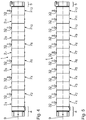
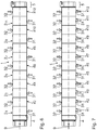
- the Fig. 4 to 7 show examples of corresponding arrangements of the fans 31, 32. These arrangements are shown by way of example for an embodiment of the continuous oven 1 with twelve oven modules 2 1 to 2 12 , 3 1 , 3 12 shown. Visible in the Fig. 4 to 7 in each case the upper furnace modules 2 1 to 2 12 , for which the fan variants are described below.
- Fig. 4 shows an arrangement in which seen in the conveying direction 9 fans 32 are arranged on each side of the furnace modules 2 i , in the illustrated embodiment, fan 32 to each of, as seen in the conveying direction 9 left side of the baking chambers 10 of the oven modules 2 i .
- the fans 32 are arranged on each second of the furnace modules 2 2 , 2 4 , 2 6 , 2 8 , 2 10 and 2 12 .
- the others, in the arrangement order in the conveying direction odd-numbered furnace modules have no fan 31/32 on.
- Fig. 4 can also have two or more consecutive furnace modules 2 i / 3 i no fan.
- Fig. 5 shows a variant of the one-sided arrangement again using the example of the one-sided arrangement again using the example of the arrangement of the fan 32, in which all the oven modules 2 i are each equipped with exactly one fan 32.
- Fig. 6 shows an arrangement in which the fans 31, 32 are arranged alternately on the one and on the other side of the baking chambers of the oven modules 2 i .
- Each second furnace module 2 i thus has a fan 31, arranged in the baking direction 9 on the right side of the baking chambers 10, respectively, and the other oven modules 2 i have an oppositely arranged fan 32.
- An alternate fan assembly according to those after Fig. 6 can also be designed so that a plurality of successive furnace modules 2 i / 3 i have the fan on the same side and, for example, after two or more such furnace modules 2 i / 3 i a change of an arrangement side of the fan towards the other side.
- each of the furnace modules 2 i has two opposing fans 31, 32.
- the continuous oven 1 is designed for continuous baking operation. It is therefore possible to bake the dough in a continuous flow between the feed module 4 and the output module 5. Depending on the required baking product throughput while both pass-back rooms 7, 8 or it may optionally only one of the two Passage back rooms 7 or 8 are used. According to the continuous passage through the passage-back rooms 7, 8 is a continuous feeding of the passage-back rooms 7, 8 with the feed module 4 and a continuous output from the passage-baking chambers 7, 9 via the output module 5 instead.
- This central control device can also be a selection of the fan to be controlled.
- the above in connection with the 4 to 6 described fan assemblies can also by appropriate selection of active fan in the complete assembly after Fig. 7 will be realized.
- the central control device can also be a conveyor of the thermal oil heater, which is not shown, are controlled.
Landscapes
- Life Sciences & Earth Sciences (AREA)
- Engineering & Computer Science (AREA)
- Food Science & Technology (AREA)
- Baking, Grill, Roasting (AREA)
- Commercial Cooking Devices (AREA)
- Tunnel Furnaces (AREA)
Priority Applications (1)
| Application Number | Priority Date | Filing Date | Title |
|---|---|---|---|
| PL19176659T PL3578048T3 (pl) | 2018-06-06 | 2019-05-27 | Przelotowy piec piekarniczy do pieczenia ciągłego |
Applications Claiming Priority (1)
| Application Number | Priority Date | Filing Date | Title |
|---|---|---|---|
| DE102018208959.0A DE102018208959A1 (de) | 2018-06-06 | 2018-06-06 | Durchlauf-Backofen für den kontinuierlichen Backbetrieb |
Publications (2)
| Publication Number | Publication Date |
|---|---|
| EP3578048A1 true EP3578048A1 (fr) | 2019-12-11 |
| EP3578048B1 EP3578048B1 (fr) | 2021-10-06 |
Family
ID=66655190
Family Applications (1)
| Application Number | Title | Priority Date | Filing Date |
|---|---|---|---|
| EP19176659.1A Active EP3578048B1 (fr) | 2018-06-06 | 2019-05-27 | Four à cuire à passage continu pour le mode de cuisson continu |
Country Status (7)
| Country | Link |
|---|---|
| US (1) | US20190373899A1 (fr) |
| EP (1) | EP3578048B1 (fr) |
| BR (1) | BR102019011645A2 (fr) |
| DE (1) | DE102018208959A1 (fr) |
| ES (1) | ES2896876T3 (fr) |
| PL (1) | PL3578048T3 (fr) |
| RU (1) | RU2019115312A (fr) |
Families Citing this family (2)
| Publication number | Priority date | Publication date | Assignee | Title |
|---|---|---|---|---|
| DE102020208674A1 (de) | 2020-07-10 | 2022-01-13 | Werner & Pfleiderer Industrielle Backtechnik Gmbh | Durchlauf-Backofen für den kontinuierlichen Backbetrieb |
| DE102021204166B4 (de) | 2021-04-27 | 2025-03-13 | Heuft Thermo-Oel GmbH & Co. KG | Tunnelofen |
Citations (7)
| Publication number | Priority date | Publication date | Assignee | Title |
|---|---|---|---|---|
| US1832374A (en) | 1927-06-20 | 1931-11-17 | Forby Theodore | Baker's apparatus |
| DE1095223B (de) | 1957-04-17 | 1960-12-22 | Vyzk Ustav Strojuu Chladicich | Durchlauf-Backofen mit mehreren uebereinander angeordneten, gegenseitig umlaufenden endlosen Foerderbandsystemen und an jeder Richtungsumkehrstelle angeordneten UEberleitorganen |
| DE2629716A1 (de) | 1975-07-10 | 1977-01-20 | Rene Voegtlin | Mehrgeschossiger bandtunnelofen zum backen von baeckerei- und konditoreierzeugnissen |
| US5826496A (en) * | 1996-07-23 | 1998-10-27 | Stein, Inc. | Cooking oven |
| DE19820061A1 (de) | 1997-06-09 | 1998-12-10 | Werner & Pfleiderer Lebensmitt | Backofen |
| EP1293127A2 (fr) * | 2001-09-14 | 2003-03-19 | FMC Technologies, Inc. | Four de cuisson avec échangeur de chaleur cintré |
| DE102016201767A1 (de) * | 2016-02-05 | 2017-08-10 | Daub Backtechnik Gmbh | Modularer Durchlaufwagenofen |
Family Cites Families (11)
| Publication number | Priority date | Publication date | Assignee | Title |
|---|---|---|---|---|
| US4245613A (en) * | 1978-11-01 | 1981-01-20 | Black Body Corporation | Tunnel oven |
| US4965435A (en) * | 1985-10-15 | 1990-10-23 | Donald P. Smith | Forced convection tunnel oven |
| FR2726433B1 (fr) * | 1994-11-07 | 1996-12-13 | Mecatherm Sa | Four a cuisson continue de produits de boulangerie, viennoiserie, patisserie et analogue |
| EP0859199B1 (fr) * | 1997-01-04 | 2004-10-20 | Heat and Control, Inc. | Four à air circulé |
| ATE249742T1 (de) * | 1997-06-09 | 2003-10-15 | Werner & Pfleiderer Lebensmitt | Backofen |
| US6526961B1 (en) * | 2000-07-10 | 2003-03-04 | Lincoln Foodservice Products, Inc | Conveyor oven |
| US6576874B2 (en) * | 2001-09-06 | 2003-06-10 | Bakers Pride | Modular heating element for a conveyor oven |
| DE102006043287B4 (de) * | 2006-09-14 | 2011-07-21 | MIWE Michael Wenz GmbH, 97450 | Thermoöl-Backofensystem |
| US20090001068A1 (en) * | 2007-06-28 | 2009-01-01 | Bramhall Marcus E | Apparatus and methods for cooling an oven conveyor motor |
| DE102015219267A1 (de) * | 2015-10-06 | 2017-04-06 | Kuchenmeister Gmbh | Backofen mit kombinierter Wärmeübertragung |
| WO2017147473A1 (fr) * | 2016-02-26 | 2017-08-31 | Provisur Technologies, Inc. | Dispositifs de cuisson et leurs procédés d'utilisation |
-
2018
- 2018-06-06 DE DE102018208959.0A patent/DE102018208959A1/de not_active Ceased
-
2019
- 2019-05-20 RU RU2019115312A patent/RU2019115312A/ru unknown
- 2019-05-27 PL PL19176659T patent/PL3578048T3/pl unknown
- 2019-05-27 ES ES19176659T patent/ES2896876T3/es active Active
- 2019-05-27 EP EP19176659.1A patent/EP3578048B1/fr active Active
- 2019-06-04 BR BR102019011645A patent/BR102019011645A2/pt not_active Application Discontinuation
- 2019-06-05 US US16/432,061 patent/US20190373899A1/en not_active Abandoned
Patent Citations (7)
| Publication number | Priority date | Publication date | Assignee | Title |
|---|---|---|---|---|
| US1832374A (en) | 1927-06-20 | 1931-11-17 | Forby Theodore | Baker's apparatus |
| DE1095223B (de) | 1957-04-17 | 1960-12-22 | Vyzk Ustav Strojuu Chladicich | Durchlauf-Backofen mit mehreren uebereinander angeordneten, gegenseitig umlaufenden endlosen Foerderbandsystemen und an jeder Richtungsumkehrstelle angeordneten UEberleitorganen |
| DE2629716A1 (de) | 1975-07-10 | 1977-01-20 | Rene Voegtlin | Mehrgeschossiger bandtunnelofen zum backen von baeckerei- und konditoreierzeugnissen |
| US5826496A (en) * | 1996-07-23 | 1998-10-27 | Stein, Inc. | Cooking oven |
| DE19820061A1 (de) | 1997-06-09 | 1998-12-10 | Werner & Pfleiderer Lebensmitt | Backofen |
| EP1293127A2 (fr) * | 2001-09-14 | 2003-03-19 | FMC Technologies, Inc. | Four de cuisson avec échangeur de chaleur cintré |
| DE102016201767A1 (de) * | 2016-02-05 | 2017-08-10 | Daub Backtechnik Gmbh | Modularer Durchlaufwagenofen |
Also Published As
| Publication number | Publication date |
|---|---|
| RU2019115312A (ru) | 2020-11-20 |
| DE102018208959A1 (de) | 2019-12-12 |
| ES2896876T3 (es) | 2022-02-28 |
| US20190373899A1 (en) | 2019-12-12 |
| BR102019011645A2 (pt) | 2019-12-24 |
| PL3578048T3 (pl) | 2022-05-30 |
| EP3578048B1 (fr) | 2021-10-06 |
Similar Documents
| Publication | Publication Date | Title |
|---|---|---|
| EP0883994B1 (fr) | Four de cuisson | |
| EP3358957B1 (fr) | Four à transfert de chaleur combiné | |
| EP1729584B1 (fr) | Four de cuisson | |
| EP3578048B1 (fr) | Four à cuire à passage continu pour le mode de cuisson continu | |
| AT399083B (de) | Durchlaufofen für backwaren | |
| EP4082343A1 (fr) | Four tunnel | |
| CH548161A (de) | Backofen. | |
| DE19820061A1 (de) | Backofen | |
| DE2435138A1 (de) | Backofen | |
| EP3578911B1 (fr) | Échangeur de chaleur tubulaire pour un four de cuisson | |
| EP1197148A2 (fr) | Four à chariots | |
| DE19539856C2 (de) | Dampfbackofen für Backwaren | |
| EP4021188B1 (fr) | Four de cuisson à passage unique pour une opération de cuisson continue | |
| EP0334001A1 (fr) | Four de passage continu pour produits de boulangerie | |
| AT376106B (de) | Backofen | |
| EP3578049B1 (fr) | Bande transporteuse continue pour un four à cuire à passage continu | |
| EP3949737B1 (fr) | Four à cuire à passage continu pour le mode de cuisson continu | |
| EP1103182A2 (fr) | Four de cuisson | |
| DE102016223041B4 (de) | Backofen | |
| DE3106833A1 (de) | Indirekt beheizter mehrzonen-durchlauf-backofen | |
| DE102024113888B3 (de) | Temperierungsanlage für die Wärmebehandlung von zu beschichtenden Werkstücken | |
| DE19922430A1 (de) | Vorrichtung zum Trocknen und Fixieren einer breitgeführten textilen Warenbahn | |
| EP0392150B1 (fr) | Four de boulangerie à circulation de gaz de chauffage | |
| DE7424900U (de) | Backofen | |
| EP2870876A1 (fr) | Four de cuisson et complément d'équipement pour fours de cuisson |
Legal Events
| Date | Code | Title | Description |
|---|---|---|---|
| PUAI | Public reference made under article 153(3) epc to a published international application that has entered the european phase |
Free format text: ORIGINAL CODE: 0009012 |
|
| STAA | Information on the status of an ep patent application or granted ep patent |
Free format text: STATUS: THE APPLICATION HAS BEEN PUBLISHED |
|
| AK | Designated contracting states |
Kind code of ref document: A1 Designated state(s): AL AT BE BG CH CY CZ DE DK EE ES FI FR GB GR HR HU IE IS IT LI LT LU LV MC MK MT NL NO PL PT RO RS SE SI SK SM TR |
|
| AX | Request for extension of the european patent |
Extension state: BA ME |
|
| STAA | Information on the status of an ep patent application or granted ep patent |
Free format text: STATUS: REQUEST FOR EXAMINATION WAS MADE |
|
| 17P | Request for examination filed |
Effective date: 20200603 |
|
| RBV | Designated contracting states (corrected) |
Designated state(s): AL AT BE BG CH CY CZ DE DK EE ES FI FR GB GR HR HU IE IS IT LI LT LU LV MC MK MT NL NO PL PT RO RS SE SI SK SM TR |
|
| STAA | Information on the status of an ep patent application or granted ep patent |
Free format text: STATUS: EXAMINATION IS IN PROGRESS |
|
| 17Q | First examination report despatched |
Effective date: 20201028 |
|
| GRAP | Despatch of communication of intention to grant a patent |
Free format text: ORIGINAL CODE: EPIDOSNIGR1 |
|
| STAA | Information on the status of an ep patent application or granted ep patent |
Free format text: STATUS: GRANT OF PATENT IS INTENDED |
|
| INTG | Intention to grant announced |
Effective date: 20210430 |
|
| GRAS | Grant fee paid |
Free format text: ORIGINAL CODE: EPIDOSNIGR3 |
|
| GRAA | (expected) grant |
Free format text: ORIGINAL CODE: 0009210 |
|
| STAA | Information on the status of an ep patent application or granted ep patent |
Free format text: STATUS: THE PATENT HAS BEEN GRANTED |
|
| AK | Designated contracting states |
Kind code of ref document: B1 Designated state(s): AL AT BE BG CH CY CZ DE DK EE ES FI FR GB GR HR HU IE IS IT LI LT LU LV MC MK MT NL NO PL PT RO RS SE SI SK SM TR |
|
| REG | Reference to a national code |
Ref country code: GB Ref legal event code: FG4D Free format text: NOT ENGLISH |
|
| REG | Reference to a national code |
Ref country code: CH Ref legal event code: EP Ref country code: AT Ref legal event code: REF Ref document number: 1435430 Country of ref document: AT Kind code of ref document: T Effective date: 20211015 |
|
| REG | Reference to a national code |
Ref country code: IE Ref legal event code: FG4D Free format text: LANGUAGE OF EP DOCUMENT: GERMAN |
|
| REG | Reference to a national code |
Ref country code: DE Ref legal event code: R096 Ref document number: 502019002424 Country of ref document: DE |
|
| REG | Reference to a national code |
Ref country code: SE Ref legal event code: TRGR |
|
| REG | Reference to a national code |
Ref country code: NL Ref legal event code: FP |
|
| REG | Reference to a national code |
Ref country code: LT Ref legal event code: MG9D |
|
| REG | Reference to a national code |
Ref country code: ES Ref legal event code: FG2A Ref document number: 2896876 Country of ref document: ES Kind code of ref document: T3 Effective date: 20220228 |
|
| PG25 | Lapsed in a contracting state [announced via postgrant information from national office to epo] |
Ref country code: RS Free format text: LAPSE BECAUSE OF FAILURE TO SUBMIT A TRANSLATION OF THE DESCRIPTION OR TO PAY THE FEE WITHIN THE PRESCRIBED TIME-LIMIT Effective date: 20211006 Ref country code: LT Free format text: LAPSE BECAUSE OF FAILURE TO SUBMIT A TRANSLATION OF THE DESCRIPTION OR TO PAY THE FEE WITHIN THE PRESCRIBED TIME-LIMIT Effective date: 20211006 Ref country code: FI Free format text: LAPSE BECAUSE OF FAILURE TO SUBMIT A TRANSLATION OF THE DESCRIPTION OR TO PAY THE FEE WITHIN THE PRESCRIBED TIME-LIMIT Effective date: 20211006 Ref country code: BG Free format text: LAPSE BECAUSE OF FAILURE TO SUBMIT A TRANSLATION OF THE DESCRIPTION OR TO PAY THE FEE WITHIN THE PRESCRIBED TIME-LIMIT Effective date: 20220106 |
|
| PG25 | Lapsed in a contracting state [announced via postgrant information from national office to epo] |
Ref country code: IS Free format text: LAPSE BECAUSE OF FAILURE TO SUBMIT A TRANSLATION OF THE DESCRIPTION OR TO PAY THE FEE WITHIN THE PRESCRIBED TIME-LIMIT Effective date: 20220206 Ref country code: PT Free format text: LAPSE BECAUSE OF FAILURE TO SUBMIT A TRANSLATION OF THE DESCRIPTION OR TO PAY THE FEE WITHIN THE PRESCRIBED TIME-LIMIT Effective date: 20220207 Ref country code: NO Free format text: LAPSE BECAUSE OF FAILURE TO SUBMIT A TRANSLATION OF THE DESCRIPTION OR TO PAY THE FEE WITHIN THE PRESCRIBED TIME-LIMIT Effective date: 20220106 Ref country code: LV Free format text: LAPSE BECAUSE OF FAILURE TO SUBMIT A TRANSLATION OF THE DESCRIPTION OR TO PAY THE FEE WITHIN THE PRESCRIBED TIME-LIMIT Effective date: 20211006 Ref country code: HR Free format text: LAPSE BECAUSE OF FAILURE TO SUBMIT A TRANSLATION OF THE DESCRIPTION OR TO PAY THE FEE WITHIN THE PRESCRIBED TIME-LIMIT Effective date: 20211006 |
|
| REG | Reference to a national code |
Ref country code: DE Ref legal event code: R097 Ref document number: 502019002424 Country of ref document: DE |
|
| PG25 | Lapsed in a contracting state [announced via postgrant information from national office to epo] |
Ref country code: SM Free format text: LAPSE BECAUSE OF FAILURE TO SUBMIT A TRANSLATION OF THE DESCRIPTION OR TO PAY THE FEE WITHIN THE PRESCRIBED TIME-LIMIT Effective date: 20211006 Ref country code: SK Free format text: LAPSE BECAUSE OF FAILURE TO SUBMIT A TRANSLATION OF THE DESCRIPTION OR TO PAY THE FEE WITHIN THE PRESCRIBED TIME-LIMIT Effective date: 20211006 Ref country code: RO Free format text: LAPSE BECAUSE OF FAILURE TO SUBMIT A TRANSLATION OF THE DESCRIPTION OR TO PAY THE FEE WITHIN THE PRESCRIBED TIME-LIMIT Effective date: 20211006 Ref country code: EE Free format text: LAPSE BECAUSE OF FAILURE TO SUBMIT A TRANSLATION OF THE DESCRIPTION OR TO PAY THE FEE WITHIN THE PRESCRIBED TIME-LIMIT Effective date: 20211006 Ref country code: DK Free format text: LAPSE BECAUSE OF FAILURE TO SUBMIT A TRANSLATION OF THE DESCRIPTION OR TO PAY THE FEE WITHIN THE PRESCRIBED TIME-LIMIT Effective date: 20211006 |
|
| PLBE | No opposition filed within time limit |
Free format text: ORIGINAL CODE: 0009261 |
|
| STAA | Information on the status of an ep patent application or granted ep patent |
Free format text: STATUS: NO OPPOSITION FILED WITHIN TIME LIMIT |
|
| 26N | No opposition filed |
Effective date: 20220707 |
|
| PG25 | Lapsed in a contracting state [announced via postgrant information from national office to epo] |
Ref country code: AL Free format text: LAPSE BECAUSE OF FAILURE TO SUBMIT A TRANSLATION OF THE DESCRIPTION OR TO PAY THE FEE WITHIN THE PRESCRIBED TIME-LIMIT Effective date: 20211006 |
|
| PG25 | Lapsed in a contracting state [announced via postgrant information from national office to epo] |
Ref country code: SI Free format text: LAPSE BECAUSE OF FAILURE TO SUBMIT A TRANSLATION OF THE DESCRIPTION OR TO PAY THE FEE WITHIN THE PRESCRIBED TIME-LIMIT Effective date: 20211006 |
|
| PG25 | Lapsed in a contracting state [announced via postgrant information from national office to epo] |
Ref country code: MC Free format text: LAPSE BECAUSE OF FAILURE TO SUBMIT A TRANSLATION OF THE DESCRIPTION OR TO PAY THE FEE WITHIN THE PRESCRIBED TIME-LIMIT Effective date: 20211006 Ref country code: LU Free format text: LAPSE BECAUSE OF NON-PAYMENT OF DUE FEES Effective date: 20220527 |
|
| PG25 | Lapsed in a contracting state [announced via postgrant information from national office to epo] |
Ref country code: IE Free format text: LAPSE BECAUSE OF NON-PAYMENT OF DUE FEES Effective date: 20220527 |
|
| GBPC | Gb: european patent ceased through non-payment of renewal fee |
Effective date: 20230527 |
|
| PG25 | Lapsed in a contracting state [announced via postgrant information from national office to epo] |
Ref country code: MK Free format text: LAPSE BECAUSE OF FAILURE TO SUBMIT A TRANSLATION OF THE DESCRIPTION OR TO PAY THE FEE WITHIN THE PRESCRIBED TIME-LIMIT Effective date: 20211006 Ref country code: CY Free format text: LAPSE BECAUSE OF FAILURE TO SUBMIT A TRANSLATION OF THE DESCRIPTION OR TO PAY THE FEE WITHIN THE PRESCRIBED TIME-LIMIT Effective date: 20211006 Ref country code: GB Free format text: LAPSE BECAUSE OF NON-PAYMENT OF DUE FEES Effective date: 20230527 |
|
| PG25 | Lapsed in a contracting state [announced via postgrant information from national office to epo] |
Ref country code: HU Free format text: LAPSE BECAUSE OF FAILURE TO SUBMIT A TRANSLATION OF THE DESCRIPTION OR TO PAY THE FEE WITHIN THE PRESCRIBED TIME-LIMIT; INVALID AB INITIO Effective date: 20190527 |
|
| PG25 | Lapsed in a contracting state [announced via postgrant information from national office to epo] |
Ref country code: MT Free format text: LAPSE BECAUSE OF FAILURE TO SUBMIT A TRANSLATION OF THE DESCRIPTION OR TO PAY THE FEE WITHIN THE PRESCRIBED TIME-LIMIT Effective date: 20211006 |
|
| PG25 | Lapsed in a contracting state [announced via postgrant information from national office to epo] |
Ref country code: GR Free format text: LAPSE BECAUSE OF NON-PAYMENT OF DUE FEES Effective date: 20211006 |
|
| PG25 | Lapsed in a contracting state [announced via postgrant information from national office to epo] |
Ref country code: GR Free format text: LAPSE BECAUSE OF NON-PAYMENT OF DUE FEES Effective date: 20211006 |
|
| PGFP | Annual fee paid to national office [announced via postgrant information from national office to epo] |
Ref country code: NL Payment date: 20250522 Year of fee payment: 7 |
|
| PGFP | Annual fee paid to national office [announced via postgrant information from national office to epo] |
Ref country code: PL Payment date: 20250508 Year of fee payment: 7 |
|
| PGFP | Annual fee paid to national office [announced via postgrant information from national office to epo] |
Ref country code: ES Payment date: 20250616 Year of fee payment: 7 |
|
| PGFP | Annual fee paid to national office [announced via postgrant information from national office to epo] |
Ref country code: BE Payment date: 20250520 Year of fee payment: 7 Ref country code: IT Payment date: 20250530 Year of fee payment: 7 |
|
| PGFP | Annual fee paid to national office [announced via postgrant information from national office to epo] |
Ref country code: FR Payment date: 20250521 Year of fee payment: 7 |
|
| PGFP | Annual fee paid to national office [announced via postgrant information from national office to epo] |
Ref country code: CH Payment date: 20250601 Year of fee payment: 7 |
|
| PGFP | Annual fee paid to national office [announced via postgrant information from national office to epo] |
Ref country code: AT Payment date: 20250509 Year of fee payment: 7 |
|
| PGFP | Annual fee paid to national office [announced via postgrant information from national office to epo] |
Ref country code: TR Payment date: 20250520 Year of fee payment: 7 |
|
| PGFP | Annual fee paid to national office [announced via postgrant information from national office to epo] |
Ref country code: CZ Payment date: 20250514 Year of fee payment: 7 |
|
| PGFP | Annual fee paid to national office [announced via postgrant information from national office to epo] |
Ref country code: SE Payment date: 20250522 Year of fee payment: 7 |
|
| PGFP | Annual fee paid to national office [announced via postgrant information from national office to epo] |
Ref country code: DE Payment date: 20250725 Year of fee payment: 7 |