EP3578079B1 - Gehäuse für ein kosmetikprodukt, insbesondere für ein pulveriges kosmetikprodukt - Google Patents
Gehäuse für ein kosmetikprodukt, insbesondere für ein pulveriges kosmetikprodukt Download PDFInfo
- Publication number
- EP3578079B1 EP3578079B1 EP19176188.1A EP19176188A EP3578079B1 EP 3578079 B1 EP3578079 B1 EP 3578079B1 EP 19176188 A EP19176188 A EP 19176188A EP 3578079 B1 EP3578079 B1 EP 3578079B1
- Authority
- EP
- European Patent Office
- Prior art keywords
- cosmetic product
- locking
- dispensing device
- control member
- dispensing
- Prior art date
- Legal status (The legal status is an assumption and is not a legal conclusion. Google has not performed a legal analysis and makes no representation as to the accuracy of the status listed.)
- Active
Links
Images


Classifications
-
- A—HUMAN NECESSITIES
- A45—HAND OR TRAVELLING ARTICLES
- A45D—HAIRDRESSING OR SHAVING EQUIPMENT; EQUIPMENT FOR COSMETICS OR COSMETIC TREATMENTS, e.g. FOR MANICURING OR PEDICURING
- A45D33/00—Containers or accessories specially adapted for handling powdery toiletry or cosmetic substances
- A45D33/02—Containers or accessories specially adapted for handling powdery toiletry or cosmetic substances with dispensing means, e.g. sprinkling means
- A45D33/025—Containers or accessories specially adapted for handling powdery toiletry or cosmetic substances with dispensing means, e.g. sprinkling means for compacts, vanity boxes or cases
-
- A—HUMAN NECESSITIES
- A45—HAND OR TRAVELLING ARTICLES
- A45D—HAIRDRESSING OR SHAVING EQUIPMENT; EQUIPMENT FOR COSMETICS OR COSMETIC TREATMENTS, e.g. FOR MANICURING OR PEDICURING
- A45D33/00—Containers or accessories specially adapted for handling powdery toiletry or cosmetic substances
- A45D33/003—Powder boxes
-
- A—HUMAN NECESSITIES
- A45—HAND OR TRAVELLING ARTICLES
- A45D—HAIRDRESSING OR SHAVING EQUIPMENT; EQUIPMENT FOR COSMETICS OR COSMETIC TREATMENTS, e.g. FOR MANICURING OR PEDICURING
- A45D33/00—Containers or accessories specially adapted for handling powdery toiletry or cosmetic substances
- A45D33/006—Vanity boxes or cases, compacts, i.e. containing a powder receptacle and a puff or applicator
- A45D33/008—Vanity boxes or cases, compacts, i.e. containing a powder receptacle and a puff or applicator comprising a mirror
-
- A—HUMAN NECESSITIES
- A45—HAND OR TRAVELLING ARTICLES
- A45D—HAIRDRESSING OR SHAVING EQUIPMENT; EQUIPMENT FOR COSMETICS OR COSMETIC TREATMENTS, e.g. FOR MANICURING OR PEDICURING
- A45D33/00—Containers or accessories specially adapted for handling powdery toiletry or cosmetic substances
- A45D33/22—Containers with lids or covers at the top and the bottom
-
- A—HUMAN NECESSITIES
- A45—HAND OR TRAVELLING ARTICLES
- A45D—HAIRDRESSING OR SHAVING EQUIPMENT; EQUIPMENT FOR COSMETICS OR COSMETIC TREATMENTS, e.g. FOR MANICURING OR PEDICURING
- A45D2200/00—Details not otherwise provided for in A45D
- A45D2200/05—Details of containers
- A45D2200/053—Transparent containers
Definitions
- the invention relates to a case for a cosmetic product, in particular a powder cosmetic product.
- a cosmetic product case Numerous examples of a cosmetic product case are known from the state of the art, in particular but not exclusively for packaging a powder cosmetic product, such as powder or other similar products used for applying makeup.
- the housing for cosmetic product comprises a cover which is mounted to be movable in rotation relative to a base by means of articulation means such as a hinge, respectively between a closed position and at least one open position. of the housing.
- Such a design has the advantage of offering a housing whose cover is permanently connected to the base so as to form a unitary assembly.
- the cover contains a mirror, it allows the wearer to apply makeup using this mirror, without needing to hold the cover.
- Such a case generally comprises locking means which are configured to lock the cover in the closed position in order in particular to prevent any unexpected opening, in particular during transport.
- the mechanical type locking means are controlled manually, that is to say that the unlocking of the cover is selectively obtained by actuating a button to control the opening of the housing.
- a dispensing device comprising dispensing means, for example a grid or a sieve, through which said cosmetic product is distributed.
- the known dispensing means have various drawbacks, one of which is the fact of not being able to selectively control the dispensing and also of not precisely controlling the dispensed quantity of cosmetic product.
- the applicator which is directly in contact with the cosmetic product delivered is then impregnated in an uncontrolled manner.
- the document FR 723 214 A describes a dispenser for pulverulent or pasty products.
- the aim of the invention is in particular to propose a new housing design comprising a dispensing device making it possible to resolve at least some of the drawbacks of the state of the art, while having a housing further having simple gestures, a pleasing aesthetics and precise and reliable dispensing of the cosmetic product.
- the housing comprises a single control member, said to be multifunction, for selectively controlling the unlocking of the first locking means of the cover and the unlocking of the second locking means of the dispensing device as well as the dispensing of the cosmetic product.
- the aesthetic appearance (or design) of the housing which is advantageously more refined, is improved, in particular by comparison with a housing which would include a button for each of the different functions.
- the use of the box is also simplified with an actuation gesture on a single control member.
- the case has good ergonomics when the unlocking function and the cosmetic product dispensing function are separated.
- each of the functions, respectively unlocking and distribution, is selectively controlled.
- the application of a first force on the control member causes the unlocking of the first locking means of the cover and of the second locking means of the dispensing device, preferably simultaneously, while the application of a second effort, greater than the first effort, causes distribution of the cosmetic product.
- the application of the first force thus corresponds to a first stroke of the control member while the second force corresponds to a second stroke of the control member, greater in distance than the first stroke.
- the unlocking of the first locking means of the cover and of the second locking means of the dispensing device is obtained by applying to the control member a determined force at least equal to the first effort.
- handling the opening of the casing is therefore not systematically accompanied by dispensing of cosmetic product, which is the reason why the unlocking and dispensing functions are said to be separate, selectively controlled.
- the case can be closed by a simple gesture, without actuating the control member.
- control in particular by applying sufficient force to the cover to fold it down in the closing direction in order to automatically cause the locking fingers to retract by cooperation of technical forms.
- the dispensing of the cosmetic product is controlled independently of the double unlocking.
- the application on the control member of a force at least equal to the second force is carried out only when a distribution of cosmetic product is desired.
- dispensing of cosmetic product can also be carried out subsequently in a completely free manner, independently of the position of said first and second means. lock.
- the user is free to be able to actuate the control member again, one or more times, to obtain an additional delivery of cosmetic product, for example when almost all of the cosmetic product previously dispensed into the cavity has been used.
- the unlocking of the first locking means of the cover and the unlocking of the second locking means of the dispensing device are carried out simultaneously or substantially simultaneously.
- the dispensing device is configured to deliver a determined dose of cosmetic product so that the quantity of cosmetic product is dispensed with precision, in a perfectly controlled manner.
- the dose of cosmetic product is not delivered directly to the applicator but in a cavity of the base in which the user then withdraws the desired amount of cosmetic product using said applicator.
- the housing comprises a space arranged between the cover and the dispensing device for storing the applicator, in particular in the closed position of the housing, by virtue of which the applicator is advantageously separated, isolated from the powder cosmetic product.
- the housing comprises at least one mirror housed inside the cover.
- the mirror and / or the applicator are arranged in an upper part of the housing which is completely separated from a lower part formed by the cavity of the base in which the cosmetic product delivered by the dispensing device is received.
- the mirror and / or the applicator are thus protected from the risk of soiling by the cosmetic product.
- the housing has better cleanliness for the user due to this separation, with the isolation of the cosmetic product in the cavity.
- the longitudinal and transverse orientations are determined in a fixed manner with respect to the base of the housing so that the open or closed position of the cover of the housing has no effect on said longitudinal and transverse orientations.
- front and rear are used with reference to the longitudinal orientation of the trihedron (L, V, T), the housing opening by rotating the cover from front to rear. around an axis O of rotation arranged at the rear of the housing.
- upstream and downstream are used with reference to the flow of the cosmetic product which takes place from upstream to downstream.
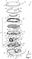
- housing 10 for a cosmetic product according to one embodiment of the invention given by way of non-limiting example.
- the cosmetic product is a pulverulent cosmetic product P, for example powder, which has been represented by a set of points in the figures.
- the housing 10 has, without limitation, a generally cylindrical shape.
- the housing 10 could have another shape, in particular a parallelepiped, in particular a square or rectangular shape.
- the housing 10 comprises a cover 12 and a base 14 which are of complementary shape.
- the cover 12 of the housing 10 is mounted to be movable in rotation relative to the base 14 about an axis O of rotation, respectively between at least one closed position ( figure 3 ) and an open position ( figures 5 , 7 or 9 ).
- the cover 12 has a wall 16 and a circumferential edge 18.
- the wall 16 is flat, said wall 16 extending horizontally either in a plane (L, T) of the trihedron when the cover 12 is in the closed position, and the edge 18 extending vertically downwards.
- the wall 16 of the cover 12 comprises an outer face 19 and an inner face 20 respectively.
- the cover 12 comprises at least one mirror 22 which is fixed inside said cover 12, against the internal face 20, by means of fixing means 24.
- the means 24 for fixing the mirror 22 are for example formed by two strips of double-sided adhesive, ie fixing by gluing, as a variant by any other equivalent fixing means.
- the mirror 22 has a reflecting face 26 intended to allow the user to see herself, in particular with the aim of applying makeup with the cosmetic product P.
- the housing 10 comprises at least one applicator 28 intended to be used for applying make-up with said cosmetic product P.
- the applicator 28 here consists of a sponge, for example made of foam, at least one side of which is used for the application of the cosmetic product P.
- the applicator 28 consists of a brush or any other equivalent means intended for the application of a cosmetic product.
- the base 14 has at least one internal cavity 30.
- the cavity 30 has a volume which is here delimited by a bottom 32 and a circumferential edge 34 of the base 14.
- the bottom 32 of the base 14 comprises an internal face 31 which is generally flat and an external face 33.
- the edge 34 of the base 14 has an opening 36 located at the front and, longitudinally on the opposite side, an opening 38 located at the rear.
- the front opening 36 and the rear opening 38 each generally have a "U" shape, open vertically upwards.
- the housing 10 comprises a dispensing device 40 which is arranged between the cover 12 and the base 14.
- the dispensing device 40 is rotatably mounted between a lowered position ( figure 3 ) and at least one raised position ( figures 5 , 7 or 9 ).
- the cover 12 is mounted so as to be able to rotate relative to the base 14 by means of first articulation means which are configured to form a hinge.
- Said first articulation means of the cover 12 comprise at least a first part 42 of the hinge which is integral with the cover 12 and a second part 44 of the hinge which is integral with the base 14.
- the second hinge part 44 comprises two respectively left and right cheeks which are connected to the edge 34, said cheeks transversely defining the rear opening 38 in which the first hinge part 42 is housed.
- first part 42 of the hinge and the second part 44 of the hinge are connected together by at least one journal, here by two journals 46 respectively left and right.
- the first part 42 of the hinge comprises at least one bore 43 and the second part 44 of the hinge comprises at least one bore 45 which, here passing through each cheek, extends until it emerges into the outer surface of the edge 34 of the base 14 in order to allow the introduction from the outside of each of the pins 46.
- the two journals 46 determine said axis O of rotation of the cover 12, which axis O of rotation is of transverse orientation.
- the dispensing device 40 is mounted to be movable in rotation relative to the base 14 by means of second articulation means configured to form a hinge.
- the second articulation means of the dispensing device 40 comprise a first part 48 of the hinge.
- the first part 48 of the hinge is connected to the base 14 by the journals 46 of the first articulation means of the cover 12.
- the first hinge part 48 has at least one hole 49 for the journals 46.
- the second hinge part 44 of the first hinge means of the cover 12 forms for the second hinge means of the dispensing device 40 a second hinge part to which the first hinge part 48 of the second hinge means is connected by pins 46.
- the first hinge part 48 of the second articulation means of the dispensing device 40 is configured to interlock with the first hinge part 42 of the first articulation means of the cover 12.
- first articulation means of the cover 12 and the second articulation means of the dispensing device 40 have the same axis O of rotation, a common axis of rotation which is here determined by the journals 46.
- the dispensing device 40 comprises a control member 50 which is intended to be actuated manually to control dispensing of the cosmetic product.
- control member 50 is a button or push button intended to be actuated manually, in particular by at least one finger.
- control member 50 is essentially housed in the front opening 36 made in the edge 34 of the base 14 so as to be accessible from the outside when the cover 12 of the housing 10 is in the closed position.
- the dispensing device 40 is configured to selectively dispense a determined dose of cosmetic product P.
- the dose of cosmetic product P is delivered into the cavity 30 that the base 14 comprises when a determined force, here pushing, is applied to the control member 50 as will be explained in more detail later.
- the cosmetic product P is received in the cavity 30 which is here formed directly by the base 14.
- the dispensing device 40 being arranged above the base 14, the flow from upstream to downstream of the cosmetic product P is advantageously carried out by gravity up to the cavity 30.
- the base 14 comprises a bottom 32 whose internal surface 31 comprises at least one concave portion to form a recess, preferably centrally positioned, and / or the base 14 comprises a bottom 32 provided with at least one wall. annular extending vertically upwards, projecting from the internal surface 31, to form a barrier intended to maintain the cosmetic product P at the center of the cavity 30.
- the base 14 comprises means 52 of protection intended to limit the risks of dispersion outside the casing 10 of the pulverulent cosmetic product P likely to be present in the cavity 30.
- the cosmetic product P possibly present in the cavity 30 is free and therefore liable to spread. out of the cavity 30, in particular during transport in a bag during which the housing 10 can be in any position.
- the means 52 of protection are preferably arranged at the level of the rear opening 38 to limit the risks of dispersion of the cosmetic product P in powder form at the level of the hinge.
- the means 52 of protection comprise for example a rim 54 which, from the lower end of the cheeks forming the second part 44 of the hinge, extends horizontally towards the inside of the cavity 30 so as to shield the passage of the hinge. cosmetic product P.
- the rim 54 is provided at its free end with a lip 56 intended to cooperate with the dispensing device 40 occupying the lowered position which is illustrated in the figures. figures 3 and 4 .
- the housing 10 does not include such means of protection at the level of the opening 36 before the base 14 since the control member 50 forms a screen on the passage of the cosmetic product P from the cavity 30 towards the exterior of housing 10.
- the cavity 30 belongs to an additional part, such as a cup, mounted inside the base 14 so as to receive the pulverulent cosmetic product P distributed by the dispensing device 40.
- the cup is mounted movably between at least a low position and a high position.
- the low position corresponds to a position in which an upper edge of the cup cooperates with the dispensing device occupying said lowered position, while the high position corresponds to a position towards which the cup is urged by elastic return means when the device distributor occupies the raised position.
- the elastic return means are for example arranged between the cup and the bottom of the base.
- the cup is configured so that, in the low position, an upper edge of the cup cooperates with an adjacent lower face of the dispensing device.
- the upper edge of the cup comprises sealing means such as a gasket capable of deforming.
- the protection means 52 described above are advantageously omitted.
- a preferred embodiment of such a dispensing device 40 configured to selectively deliver a dose of powder cosmetic product P will be described below.
- the dispensing device 40 comprises a reservoir 60 intended to contain said powdered cosmetic product P.
- the dispensing device 40 comprises a cup 58 at least partially delimiting said reservoir 60 which is closed by a cover 62.
- the bucket 58 has a wall 64 the periphery of which is delimited by an edge 66 which extends vertically on either side of the wall 64.
- the edge 66 has a stepped profile, a lower part of the edge 66 being connected to an upper part by a shoulder 68 which is intended to cooperate with the cover 62.
- the wall 64 of the cup 58 has a lower face 65 and an upper face 67.
- the wall 64 of the cup 58 comprises a supply network 70 formed by orifices 72 which are in communication with the reservoir 60 and therefore the cosmetic product P.
- the reservoir 60 is made in two parts which, respectively formed by the cup 58 and the cover 62, are assembled by means of first fixing means.
- the first means for fixing the bucket 58 and the cover 62 are configured to achieve fixing by elastic interlocking.
- the first fixing means comprise, on the one hand, notches 74 formed in the upper part of the edge 66 of the cup 58 in which lugs 76 carried by an edge 78 of the cover 62 engage.
- the cover 62 is fixed to the cup 58 in a non-removable manner.
- the cover 62 is fixed to the cup 58 in a removable manner, the removable cover 62 then allowing the reservoir 60 to be recharged with cosmetic product P.
- the reservoir 60 is made in one piece.
- the cover 62 comprises a housing 80 configured to receive all or part of the applicator 28 for said cosmetic product P.
- the housing 80 of the applicator 28 is provided in the upper part of the cover 62.
- the housing 80 is delimited at the bottom by a wall 82 of the cover 62 and on the periphery by an upper part of the edge 78.
- the wall 82 of the cover 62 has an upper face 81 and a lower face 83, here respectively flat.
- the housing 80 of the cover 62 accommodates only a part of the applicator 28, the other part being received inside the cover 12 provided with the mirror 22 so that the housing 10 has a small overall size.
- the mirror 22 and / or the applicator 28 are arranged in the upper part of the housing 10, between the cover 12 and the dispensing device 40, so that the mirror 22 and / or the applicator 28 are isolated from the product.
- cosmetic P which is present in particular in the cavity 30 of the base 14, i.e. in the lower part of the housing 10.
- Such a design of the housing 10 makes it possible to preserve the mirror 22 and / or the applicator 28 from the risk of soiling by the cosmetic product P, thanks to which the housing 10 presents good cleanliness or hygiene for the user.
- the cover 62 comprises at least one region, preferably transparent, made in the wall 82 so as to be able to visually examine through said zone the quantity of cosmetic product P present in the reservoir 60 of the dispensing device 40.
- the dispensing device 40 comprises a screen 84 comprising a flat wall 86, the periphery of which is delimited by an edge 88.
- the screen 84 comprises a distribution network 90 formed by orifices 92 in communication with the cavity 30 which the base 14 comprises.
- the orifices 92 of the screen 84 which is located downstream are offset with respect to the orifices 72 of the cup 58 which is located upstream so as to prevent a direct flow of the cosmetic product P from the reservoir 60 towards said cavity 30.
- the cup 58 and the screen 84 are assembled by means of second fastening means, preferably similar to the first fastening means of the cover 62, that is to say fastening means by elastic interlocking.
- the second fastening means comprise notches 94 formed in the edge 88 of the screen 84 and in which lugs 96 are received, which lugs 96 are carried by the lower part of the edge 66 of the cup 58 and arranged inside the latter. this.
- the wall 86 of the screen 84 respectively comprises an upper face 98 and a lower face 99.
- the dispensing device 40 comprises a metering plate 100 to which said control member 50 is integral.
- control member 50 is made in one piece, integrally, with the metering plate 100.
- the metering plate 100 comprises a metering network 102 formed by through orifices 104 intended to transfer a dose of cosmetic product P from the reservoir 60 to the cavity 30.
- the metering plate 100 is arranged between the cup 58 and the screen 84 and free to move relative to the cup 58 and the screen 84 which are fixed together.
- the dispensing device 40 forms a unitary assembly which is movably mounted around the axis O of rotation between at least the lowered position and a raised position.
- the cup 58 and the cover 62 delimiting the reservoir 60 are fixed together by the first fixing means 74, 76 while the cup 58 is also fixed to the screen 84 by the second fixing means 94, 96 , whereby said unitary assembly comprising the reservoir 60 and distribution means comprising the cup 58, the metering plate 100 and the sieve 84.
- the metering plate 100 is mounted to move in translation along the longitudinal orientation between at least one metering position and a dispensing position.
- the dosage position of the plate 100 corresponds to a position in which the orifices 104 of the dosing network 102 of the plate 100 are aligned with the orifices 72 of the supply network 70 of the cup 58 to receive a dose of cosmetic product P from tank 60.
- the dispensing position of the plate 100 corresponds to a position in which the orifices 104 of the dosage network 102 of the plate 100 are aligned with the orifices 92 of the distribution network 90 in order to dispense said dose of cosmetic product P in the cavity 30.
- the orifices 104 of the metering network 102 of the metering plate 100 are closed by the upper face 98 of the screen 84.
- the orifices 104 of the metering network 102 of the metering plate 100 are closed off by the lower face 65 of the cup 58.
- the dispensing device 40 comprises means for guiding in translation the metering plate 100.
- the means for guiding the metering plate 100 comprise for example at least one rib 106 configured to cooperate with at least one slot 108.
- the metering plate 100 comprises at least one rib 106, here two left and right ribs, which protrude from a lower face 105 of the plate 100, the two ribs 106 extending parallel in the longitudinal orientation. .
- the screen 84 comprises at least one guide slot 108, here two left and right slots 108 which extend parallel in the longitudinal direction.
- the metering plate 100 is guided longitudinally in translation between said metering and dispensing positions.
- the movement of the metering plate 100 from the metering position to the dispensing position is selectively controlled by actuating said control member 50.
- the metering plate 100 is automatically returned to the metering position by elastic return means 110.
- the means 110 for elastic return of the metering plate 100 to the metering position are formed by two elastically deformable arms 112.
- the arms 112 are made in a single piece, integrally, with said metering plate 100.
- the arms 112 are arranged longitudinally at the rear of the metering plate 100 and rest against the edge 88 of the screen 84.
- the housing 10 for cosmetic product comprises first locking means 114 configured to lock the cover 12 in the closed position, said closed position being illustrated on the figures. figures 3 and 4 .
- the case 10 for a cosmetic product comprises second locking means 116 configured to lock the dispensing device 40 in the lowered position, said lowered position being more particularly illustrated on the figure. figure 4 .
- the first means 114 for locking the cover 12 and the second means 116 for locking the dispensing device 40 are of the controlled type, that is to say that at least their unlocking is controlled by acting manually on a control member.
- the first locking means 114 and the second locking means 116 are respectively mounted to move between a locked position and an unlocked position.
- control member 50 of the dispensing device 40 controls the unlocking of the first means 114 for locking the cover 12 and unlocking the second locking means 116 for the dispensing device 40.
- control member 50 is a multifunction member which, on the one hand, controls a double unlocking and, on the other hand, a distribution of the cosmetic product P.
- At least part of the first means 114 for locking the cover 12 and a part of the second means 116 for locking the dispensing device 40 are integral with the control member 50.
- the first locking means 114 comprise at least one so-called upper locking finger 118 which is carried by an upper part of said control member 50 and protrudes forward.
- the upper locking finger 118 is mounted movable in translation with the control member 50 (integral with the metering plate 100), respectively between the locked position and the unlocked position of the first locking means 114.
- the upper locking finger 118 cooperates with at least one complementary notch 120 of the cover 12, here provided inside the edge 18 of the cover 12 from which the notch 120 protrudes rearwardly.
- the upper locking finger 118 is automatically returned to the locked position, urged forward by the elastic return means 110 of the metering plate 100.
- the second locking means 116 comprise at least one so-called lower locking finger 122 which is carried by said control member 50 and protrudes forward.
- the lower locking finger 122 is mounted to move in translation with the control member 50 (integral with the metering plate 100), respectively between the locked position and the unlocked position of the second locking means 116.
- the lower locking finger 122 cooperates with at least one complementary notch 124 of the base 14, here formed at the level of the front opening 36, inside the edge 34 of the base 14 from which the notch 124 protrudes rearwardly.
- the lower locking finger 122 is automatically returned to the locked position, urged forward by the elastic return means 110 of the metering plate 100.
- the return means towards the locked position of the first locking means 114 and of the second locking means 116 are formed by the elastic return means 110 of the metering plate 100 of the dispensing device 40.
- first locking means 114 and the second locking means 116 are of identical configuration so that the actuation of the control member 50 simultaneously causes their respective unlocking.
- first locking means 114 and / or the second locking means 116 are configured to allow automatic locking during a closing manipulation of the housing 10, without manual actuation of the control member 50.
- the upper locking finger 118 comprises a frustoconical surface 126 and / or the associated notch 120 of the cover 12 comprises a frustoconical surface 128.
- the lower locking finger 122 comprises a frustoconical surface 130 and / or the associated notch 124 of the base 14 comprises a frustoconical surface 132.
- the dispensing device 40 comprises stop means which intervene, at the end of the travel, when the metering plate 100 reaches the dispensing position.
- the stop means are integral with the control member 50 which comprises a first stop face 134 and / or a second stop face 136.
- control member 50 comprises a first stop face 134 and a second stop face 136 which, extending vertically, are arranged at the rear of said control member 50, on the side opposite to the fingers 118 and 122 of locking.
- the first stop face 134 comes into contact with a part of the edge 78 of the cover 62, alternatively with a part of the edge 66 of the cup 58 according to the design of the reservoir 60, and the second stop face 136 comes into contact with a part of the screen 84 which is located at the front and in which the edge 88 is interrupted.
- the elastic return means 110 are preserved against the application of an excessive force on the control member 50.
- control member 50 comprises a flange 138 which, projecting longitudinally rearwardly from its upper part, is configured here to cover the cover 62 in order to hide the play present between the member 50 of control and the dispensing device 40, so as to conceal it to preserve the aesthetics of the housing 10.
- the unlocking of the first locking means 114 and of the second locking means 116 is preferably obtained simultaneously when the control member 50 is actuated manually, ie a double unlocking.
- the unlocking and dispensing of a dose of cosmetic product are advantageously separate, that is to say in particular that the actuation of the control member 50 to control the unlocking does not systematically cause a dispensing of cosmetic product. P.
- the distribution device 40 is configured so that the application of a first force F1, called unlocking force, on said control member 50 causes an unlocking of the first locking means 114 and of the second locking means 116.
- the application on the control member 50 of a second force F2, said to be distribution, greater than said first unlocking force F1, causes the distribution of a dose of cosmetic product P, thanks to which the distribution of the cosmetic product P is dissociated from the handling of opening and closing of the housing.
- control member 50 is a pusher so that said control member 50 is actuated by manually applying a thrust force to it, oriented longitudinally and directed from front to rear.
- the housing 10 is closed, in particular capable of being then easily transported, the housing 10 forming a nomadic object offering "all in one", namely at least one mirror 22, an applicator 28 and the powdered cosmetic product P selectively delivered, on demand, by the dispensing device 40 completely integrated into the housing 10.
- the cover 12 of the housing 10 occupies the closed position, the first locking means 114 being in the locked position, while the dispensing device 40 occupies the lowered position, the second locking means 116 being in the locked position.
- a force at least equal to the first unlocking force F1 is applied to the control member 50, which simultaneously causes the unlocking of the first locking means 114 and the unlocking of the second locking means 116.
- the cover 12 of the housing 10 then occupies a first open position, called a pre-opening position, the first locking means 114 being in the unlocked position, while the dispensing device 40 occupies a first raised position, the second locking means 116 also being in the unlocked position.
- the figure 6 illustrates the dosing plate 100 in the dosing position in which the orifices 104 of the dosing network 102 of the plate 100 are advantageously aligned with the orifices 72 of the supply network 70 of the cup 58 to receive a dose of cosmetic product P from the reservoir 60.
- the application of a force at least equal to the first force F1 on the control member 50 causes the front-to-rear sliding of the metering plate 100 along a first stroke, called the unlocking stroke.
- the metering plate 100 then occupies an intermediate position between the metering position and the dispensing position.
- first locking means 114 and the second locking means 116 are configured so that the first unlocking stroke is reduced, preferably short.
- the distribution device 40 comprises a network 102 for dosing the plate 100 and a distribution network 90 for the sieve 84 which are configured so as not to be in communication when the dosing plate 100 occupies said intermediate position which is reached after the first unlocking stroke.
- the application of a force at least equal to the first force F1 but less than the second distribution force F2 corresponds for example to the actuation which will be carried out by the user wishing to use the mirror 22 housed in the inside of the housing cover 12 10.
- the cover 12 is manually raised to be driven in rotation about the axis O from the first pre-opening position to at least one other open position such as the second open position, called maximum opening, illustrated on the figures 7 and 8 .
- the dispensing device 40 is maintained in said first raised position previously occupied on the figures 5 and 6 , in particular so as not to obscure the mirror 22.
- the delivery of at least one dose can then be selectively controlled by applying an appropriate pushing force. on the control member 50, that is to say a force greater than or equal to said second distribution force F2.
- such a force at least equal to said second distribution force F2 may or may not be applied in the continuity of the initial force at least equal to the first force F1 which caused the double unlocking.
- unlocking and distribution functions are advantageously separate and each controlled selectively, independently of one another.
- the application of the initial force can for example be voluntarily interrupted after obtaining the double unlocking to use the mirror 22 or else to examine the contents of the cavity 30.
- the dispensing device 40 is then raised in order to determine whether or not a cosmetic product dispensing is necessary.
- the cavity 30 may include a residual quantity of cosmetic product P which would not have been completely used so that the distribution of a new dose is not necessary, in particular if the user wishes to carry out a simple touch-up. of makeup.
- control of the dispensing of a dose of cosmetic product P is independent of the position of the first locking means 114 and of the second locking means 116, which are automatically returned to the locked position by the elastic return means 110 of the 100 dosing plate.
- the distribution is controlled when the distribution device 40 is in the first raised position illustrated on the figures. figures 6 and 8 so that the dose of cosmetic product P delivered falls into the cavity 30 which the base 14 comprises.
- the manual application on the control member 50 of a thrust force greater than or equal to said second distribution force F2 causes the distribution of a dose of cosmetic product P.
- the application on the member 50 of this force at least equal to the second force F2 causes the sliding of the metering plate 100, longitudinally from front to rear, from the metering position to the dispensing position.
- the application of said second force F2 is made particularly simple for the user because no precise dosage of the force is necessary, the force being able to be applied without restraint.
- the user can push technically on the control member 50 without worrying about the risk of applying too great a force, thanks to the end-of-travel stop means formed by the stop faces 134, 136.
- a comparison between figures 6 and 8 advantageously makes it possible to visualize the cancellation of the play initially present between the rear of the control member 50 and the dispensing device 40 and the abutment of said faces 134 and 136.
- the application on the control member 50 of a thrust force at least equal to said second distribution force F2 causes the metering plate 100 to slide to the distribution position.
- the orifices 104 of the dosing network 102 of the plate 100 are advantageously aligned with the orifices 92 of the distribution network 90 of the sieve 84, the dose of cosmetic product P then flows by gravity towards the cavity 30.
- control of the dispensing of a dose of cosmetic product P can be carried out once but also repeated depending on the quantity of cosmetic product P desired.
- the abutment of said faces 134 and 136 of the control member 50 informs the user that the distribution of the dose has been obtained, that consequently the application of the force can cease.
- the metering plate 100 is automatically returned by the elastic return means 110 to the metering position.
- the orifices 104 of the metering network 102 will automatically fill with cosmetic product P, which then flows due to their alignment from the orifices 72 of the network 70 of feeding the bucket 58 in communication with the reservoir 60.
- the dispensing device 40 is then again ready to deliver a dose of cosmetic product P.
- the user can take hold of the applicator 28 and manually raise the dispensing device 40 to access the cosmetic product P contained in the cavity 30. .
- the dispensing device 40 is driven around the axis O of rotation from the first raised position previously occupied to a second raised position such as that illustrated in the figures. figures 9 and 10 .
- the dispensing device 40 can, if necessary, be lowered, in particular with a view to using the mirror 22.
- the closing manipulation is advantageously obtained with a simplified gesture, without actuation of the control member 50, by folding the cover 12 from an open position to the closed position.
- Closing of the housing 10 is for example obtained by pressing on the cover 12 or by tightening it with the base 14 in a clamping movement.
- the frustoconical surfaces 126 and 128 forming ramps will cooperate together to cause the upper locking finger 118 to retract, preferably by a retraction of the metering plate 100 towards the unlocked position. against the elastic return means 110.
- the retraction of the upper locking finger 118 is obtained by an elastic deformation, in particular of the upper part of the control member 50 comprising said upper locking finger 118.
- the retraction of the upper locking finger 118 may result from a combination of a retreat of the plate 100 and an elastic deformation.
- the lower locking finger 122 comprises a frustoconical surface 130 and the associated notch 124 of the base 14 comprises a frustoconical surface 132.
- the upper locking finger 118 and the lower locking finger 122 each comprise a technical form, such as a frustoconical surface, configured to obtain automatic locking without actuation of said control member 50.
- said frustoconical surfaces 130 and 132 of the lower locking finger 122 will cooperate together during the closing manipulation of the housing 10 to automatically cause the retraction of the lower locking finger 122.
- the retraction results from a retreat of the metering plate 100 towards the unlocked position against the elastic return means 110 which ensure automatic return of said lower locking finger 122.
- the retraction of the lower locking finger 122 is obtained by an elastic deformation, or even a combination of a retreat of the metering plate 100 and an elastic deformation.
- At least one of the locking fingers 118, 122 and / or at least one of the associated notches 120, 124 is provided with a technical form, such that at least one frustoconical surface, preferably each of said fingers 118, 122 of locking and said notches 120, 124 associated.
- first locking means and the second locking means are configured so that the double unlocking and the dispensing of cosmetic product are carried out simultaneously and no longer successively, in a separate manner.
- each opening manipulation by manual actuation of the control member consequently causes a distribution of cosmetic product in the cavity.
- the gestures of use are however further simplified when there is only one determined force to be applied to cause a single unlocking stroke which is then the same as the stroke. distribution carried out by the metering plate between the metering position and the dispensing position.
- the dispensing device is advantageously configured to deliver a determined dose of cosmetic product.
- the dispensing device could be simplified by having only two parts (and not three), a first part fixed and a second movable part, relative to the first part, between an inactive position in which the cosmetic product is not dispensed and an active position in which the cosmetic product is dispensed.
- the quantity of cosmetic product is however not controlled in a precise manner since the flow of the cosmetic product in the active position is only interrupted when one stops applying a force allowing the second movable part to be advantageously automatically recalled to the inactive position by associated return means.
Landscapes
- Closures For Containers (AREA)
- Containers And Packaging Bodies Having A Special Means To Remove Contents (AREA)
Claims (15)
- Behälter (10) für ein Kosmetikprodukt (P), insbesondere ein pulverförmiges Kosmetikprodukt, der mindestens umfasst:- einen Deckel (12), der in Bezug auf eine Basis (14) zwischen mindestens einer geschlossenen Stellung und einer offenen Stellung des Behälters drehbeweglich angebracht ist,- erste Verriegelungsmittel (114), um den Deckel (12) in geschlossener Stellung zu verriegeln,- eine Ausgabevorrichtung (40), die, zwischen dem Deckel (12) und der Basis (14) angeordnet, in Bezug auf die Basis (14) zwischen mindestens einer abgesenkten Stellung und einer angehobenen Stellung drehbeweglich angebracht ist, wobei die Ausgabevorrichtung (40) ein Bedienelement (50) umfasst, das dazu bestimmt ist, betätigt zu werden, um eine Ausgabe des Kosmetikprodukts zu steuern,- zweite Verriegelungsmittel (116), um die Ausgabevorrichtung (40) in der abgesenkten Stellung zu verriegeln,
wobei das Bedienelement (50) der Ausgabevorrichtung (40) dafür konfiguriert ist, das Entriegeln der ersten Verriegelungsmittel (114) des Deckels (12) und das Entriegeln der zweiten Verriegelungsmittel (116) der Ausgabevorrichtung (40) zu steuern. - Behälter nach Anspruch 1, dadurch gekennzeichnet, dass die Ausgabevorrichtung (40) ein Reservoir (60) umfasst, das dazu bestimmt ist, Kosmetikprodukt (P) zu enthalten.
- Behälter nach Anspruch 1 oder 2, dadurch gekennzeichnet, dass die Basis (14) einen Hohlraum (30) umfasst, der dazu bestimmt ist, das von der Ausgabevorrichtung (40) ausgegebene Kosmetikprodukt (P) aufzunehmen.
- Behälter nach einem der Ansprüche 1 bis 3, dadurch gekennzeichnet, dass die Ausgabevorrichtung (40) dafür konfiguriert ist, selektiv eine bestimmte Dosis Kosmetikprodukt (P) auszugeben.
- Behälter nach einem der Ansprüche 1 bis 4, dadurch gekennzeichnet, dass der Deckel (12) mittels ersten Gelenkmitteln (42, 44, 46) in Bezug auf die Basis (14) drehbeweglich angebracht ist, und die Ausgabevorrichtung (40) mittels zweiten Gelenkmitteln (48, 44, 46) in Bezug auf die Basis (14) drehbeweglich angebracht ist, wobei die ersten Gelenkmittel (42, 44, 46) und zweiten Gelenkmittel (48, 44, 46) ein und dieselbe Drehachse (O) aufweisen.
- Behälter nach Anspruch 1 in Kombination mit den Ansprüchen 2 bis 4, dadurch gekennzeichnet, dass die Ausgabevorrichtung (40) mindestens umfasst:- eine Schale (58), die mindestens zum Teil das Reservoir (60) begrenzt, das, dazu bestimmt, das Kosmetikprodukt (P) zu enthalten, von einer Abdeckung (62) verschlossen wird, wobei die Schale (58) ein Zuführnetz (70) umfasst, das von Öffnungen (72) gebildet wird, die mit dem Reservoir (60) in Kommunikation stehen,- ein Sieb (84), das ein Ausgabenetz (90) umfasst, das von Öffnungen (92) gebildet wird, die mit einem Hohlraum (30), den die Basis (14) umfasst, in Kommunikation stehen, wobei die Öffnungen (92) des Siebs (84) in Bezug auf die Öffnungen (70) der Schale (58) versetzt sind, um ein direktes Auslaufen des Kosmetikprodukts (P) aus dem Reservoir (60) in den Hohlraum (30), den die Basis (14) umfasst, zu verhindern, und- eine Dosierplatte (100), die, fest mit dem Bedienelement (50) verbunden, ein Dosiernetz (102) umfasst, das von durchgehenden Öffnungen (104) gebildet wird, wobei die Dosierplatte (100) zwischen der Schale (58) und dem Sieb (84) angeordnet und verschiebebeweglich angebracht ist zwischen mindestens:• einer Dosierstellung, in der die Öffnungen (104) des Dosiernetzes (102) der Platte (100) zu den Öffnungen (72) des Zuführnetzes (70) der Schale (58) ausgerichtet sind, um eine aus dem Reservoir (60) stammende Dosis Kosmetikprodukt (P) aufzunehmen, und• einer Ausgabestellung, in der die Öffnungen (104) des Dosiernetzes (102) der Platte (100) zu den Öffnungen (92) des Ausgabenetzes (90) ausgerichtet sind, um die Dosis Kosmetikprodukt (P) in den Hohlraum (30) auszugeben.
- Behälter nach Anspruch 6, dadurch gekennzeichnet, dass die Ausgabevorrichtung (40) Mittel (106, 108) zum Führen der Dosierplatte (100) in der Verschiebebewegung umfasst.
- Behälter nach Anspruch 6 oder 7, dadurch gekennzeichnet, dass die Dosierplatte (100) in der Bewegung von der Dosierstellung zur Ausgabestellung gesteuert wird, indem das Bedienelement (50) betätigt wird.
- Behälter nach einem der Ansprüche 6 bis 8, dadurch gekennzeichnet, dass die Dosierplatte (100) von elastischen Rückstellmitteln (110) automatisch zur Dosierstellung zurückgestellt wird.
- Behälter nach Anspruch 9, dadurch gekennzeichnet, dass die ersten Verriegelungsmittel (114) und die zweiten Verriegelungsmittel (116) von einer verriegelten Stellung zu einer entriegelten Stellung gesteuert werden, indem das Bedienelement (50) betätigt wird, und dadurch, dass die ersten Verriegelungsmittel (114) und die zweiten Verriegelungsmittel (116) von den elastischen Rückstellmitteln (110) der Dosierplatte (100) automatisch in die verriegelte Stellung zurückgestellt werden.
- Behälter nach einem der Ansprüche 1 bis 10, dadurch gekennzeichnet, dass die ersten Verriegelungsmittel (114) und/oder die zweiten Verriegelungsmittel (116) dafür konfiguriert sind, sich bei einem Schließvorgang des Behälters automatisch, ohne manuelles Betätigen des Bedienelements (50), zu verriegeln.
- Behälter nach einem der Ansprüche 6 bis 11, dadurch gekennzeichnet, dass die Abdeckung (62) eine Aufnahme (80) umfasst, die dafür konfiguriert ist, einen ganzen oder einen Teil mindestens eines Applikators (28) für das Kosmetikprodukt (P) aufzunehmen.
- Behälter nach einem der Ansprüche 6 bis 12, dadurch gekennzeichnet, dass die Abdeckung (62) mindestens einen transparenten Bereich umfasst, um durch den Bereich hindurch die Menge an Kosmetikprodukt (P), die im Reservoir (60) der Ausgabevorrichtung (40) vorhanden ist, visuell überprüfen zu können.
- Behälter nach einem der Ansprüche 1 bis 13, dadurch gekennzeichnet, dass die Ausgabevorrichtung (40) so konfiguriert ist, dass das Aufbringen einer ersten, sogenannten Entriegelungskraft (F1) auf das Bedienelement (50) ein Entriegeln der ersten Verriegelungsmittel (114) und ein Entriegeln der zweiten Verriegelungsmittel (116) bewirkt, und das Aufbringen einer zweiten, sogenannten Ausgabekraft (F2) auf das Bedienelement (50), die größer ist als die erste Entriegelungskraft (F1), die Ausgabe des Kosmetikprodukts (P) bewirkt.
- Behälter nach Anspruch 14, dadurch gekennzeichnet, dass das Aufbringen der ersten Entriegelungskraft (F1) auf das Bedienelement (50) gleichzeitig das Entriegeln der ersten Verriegelungsmittel (114) und der zweiten Verriegelungsmittel (116) bewirkt.
Applications Claiming Priority (1)
| Application Number | Priority Date | Filing Date | Title |
|---|---|---|---|
| FR1854854A FR3081689B1 (fr) | 2018-06-05 | 2018-06-05 | Boitier pour produit cosmetique, notamment un produit cosmetique pulverulent |
Publications (2)
| Publication Number | Publication Date |
|---|---|
| EP3578079A1 EP3578079A1 (de) | 2019-12-11 |
| EP3578079B1 true EP3578079B1 (de) | 2020-08-26 |
Family
ID=63080136
Family Applications (1)
| Application Number | Title | Priority Date | Filing Date |
|---|---|---|---|
| EP19176188.1A Active EP3578079B1 (de) | 2018-06-05 | 2019-05-23 | Gehäuse für ein kosmetikprodukt, insbesondere für ein pulveriges kosmetikprodukt |
Country Status (4)
| Country | Link |
|---|---|
| US (1) | US11375795B2 (de) |
| EP (1) | EP3578079B1 (de) |
| CN (1) | CN110558705B (de) |
| FR (1) | FR3081689B1 (de) |
Families Citing this family (2)
| Publication number | Priority date | Publication date | Assignee | Title |
|---|---|---|---|---|
| FR3086850B1 (fr) * | 2018-10-09 | 2020-09-25 | Albea Services | Boitier pour produit cosmetique pulverulent comportant un dispositif d'ouverture-fermeture perfectionne |
| FR3128857B1 (fr) * | 2021-11-09 | 2023-09-29 | Albea Services | Boîtier autonettoyant pour produit cosmetique pulverulent |
Family Cites Families (9)
| Publication number | Priority date | Publication date | Assignee | Title |
|---|---|---|---|---|
| FR723214A (fr) * | 1931-09-22 | 1932-04-05 | Distributeur pour produits pulvérulents ou pâteux | |
| GB9828332D0 (en) * | 1998-12-23 | 1999-02-17 | Crown Cork & Seal Tech Corp | Cosmetic compact |
| US8181828B2 (en) * | 2008-10-22 | 2012-05-22 | David M. Deans and Jerilyne T. Deans | System and method for storing and dispensing a powder |
| US8235059B2 (en) * | 2009-08-26 | 2012-08-07 | Zen Design Solutions Limited | Container for powder products and scraper therefor |
| FR2954056B1 (fr) * | 2009-12-23 | 2014-07-25 | Rexam Simandre | Systeme d'application d'un produit pulverulent |
| US8839803B2 (en) * | 2010-01-28 | 2014-09-23 | Thomas F. Holloway | Rotationally controlled cosmetic powder dose dispenser |
| US8387627B2 (en) * | 2010-08-25 | 2013-03-05 | Elcos America, Inc. | Compact powder case |
| KR101209874B1 (ko) * | 2011-06-08 | 2012-12-18 | (주) 이루팩 | 회전형 화장품 케이스 |
| FR3043897B1 (fr) * | 2015-11-24 | 2019-05-24 | Albea Services | Boitier pour produit cosmetique |
-
2018
- 2018-06-05 FR FR1854854A patent/FR3081689B1/fr active Active
-
2019
- 2019-05-23 EP EP19176188.1A patent/EP3578079B1/de active Active
- 2019-06-04 CN CN201910481811.0A patent/CN110558705B/zh active Active
- 2019-06-05 US US16/432,884 patent/US11375795B2/en active Active
Non-Patent Citations (1)
| Title |
|---|
| None * |
Also Published As
| Publication number | Publication date |
|---|---|
| US20190365073A1 (en) | 2019-12-05 |
| CN110558705B (zh) | 2024-05-10 |
| FR3081689B1 (fr) | 2021-09-17 |
| EP3578079A1 (de) | 2019-12-11 |
| CN110558705A (zh) | 2019-12-13 |
| US11375795B2 (en) | 2022-07-05 |
| FR3081689A1 (fr) | 2019-12-06 |
Similar Documents
| Publication | Publication Date | Title |
|---|---|---|
| EP2091836B1 (de) | Flüssigproduktspender | |
| EP2500277B1 (de) | Abfüllvorrichtung für einen Flakon | |
| EP1743546B1 (de) | Produktverpackung und -ausgabevorrichtung mit mehreren Behältern und Schminkverfahren unter Verwendung einer derartigen Vorrichtung | |
| EP2935037B1 (de) | Zurückziehbares deckelsystem und mit einem solchen system ausgestattete verpackungseinheit zum aufbewahren und auftragen eines produktes | |
| FR2923810A1 (fr) | Tete de distribution du type a declenchement par gachette. | |
| FR2629988A1 (fr) | Distributeur rechargeable comportant un piston translatable | |
| EP2916964A1 (de) | Flüssigproduktspender | |
| EP3490407B1 (de) | Vorrichtung zum verpacken eines kosmetikproduktes | |
| WO2015055931A1 (fr) | Dispositif de conditionnement d'un distributeur de produit fluide | |
| FR2923811A1 (fr) | Recipient equipe d'un dispositif de securite. | |
| EP3578079B1 (de) | Gehäuse für ein kosmetikprodukt, insbesondere für ein pulveriges kosmetikprodukt | |
| EP4005430B1 (de) | Mechanismus für ein kosmetikprodukt, insbesondere für eine kleine menge an lippenstift, und behälter, der einen solchen mechanismus umfasst | |
| FR3058031B1 (fr) | Dispositif pour la distribution d'un produit | |
| FR3136936A1 (fr) | Récipient pour produits cosmétiques | |
| WO2009147350A2 (fr) | Dispositif de distribution de produit fluide | |
| FR2976163A1 (fr) | Ensemble de conditionnement et de distribution d'un produit cosmetique | |
| FR3042959A1 (fr) | Dispositif de conditionnement pour un produit a distribuer, notamment pour un parfum | |
| FR2954056A1 (fr) | Systeme d'application d'un produit pulverulent | |
| EP1482283A1 (de) | Schubladendosierer | |
| FR3005558A1 (fr) | Dispositif de conditionnement d'un produit cosmetique | |
| FR2620314A1 (fr) | Brosse a dents avec alimentation automatique en pate dentifrice | |
| FR3067953A1 (fr) | Dispositif de distribution de produit provenant d'un recipient | |
| WO2023111155A1 (fr) | Dispositif d'application d'un produit cosmétique rechargeable | |
| WO2015124864A1 (fr) | Dispositif pour l'application d'un produit cosmétique | |
| FR3005557A1 (fr) | Dispositif de conditionnement d'un produit cosmetique |
Legal Events
| Date | Code | Title | Description |
|---|---|---|---|
| PUAI | Public reference made under article 153(3) epc to a published international application that has entered the european phase |
Free format text: ORIGINAL CODE: 0009012 |
|
| STAA | Information on the status of an ep patent application or granted ep patent |
Free format text: STATUS: THE APPLICATION HAS BEEN PUBLISHED |
|
| AK | Designated contracting states |
Kind code of ref document: A1 Designated state(s): AL AT BE BG CH CY CZ DE DK EE ES FI FR GB GR HR HU IE IS IT LI LT LU LV MC MK MT NL NO PL PT RO RS SE SI SK SM TR |
|
| AX | Request for extension of the european patent |
Extension state: BA ME |
|
| STAA | Information on the status of an ep patent application or granted ep patent |
Free format text: STATUS: REQUEST FOR EXAMINATION WAS MADE |
|
| 17P | Request for examination filed |
Effective date: 20200117 |
|
| RBV | Designated contracting states (corrected) |
Designated state(s): AL AT BE BG CH CY CZ DE DK EE ES FI FR GB GR HR HU IE IS IT LI LT LU LV MC MK MT NL NO PL PT RO RS SE SI SK SM TR |
|
| RIC1 | Information provided on ipc code assigned before grant |
Ipc: A45D 33/00 20060101ALI20200130BHEP Ipc: A45D 33/02 20060101AFI20200130BHEP |
|
| GRAP | Despatch of communication of intention to grant a patent |
Free format text: ORIGINAL CODE: EPIDOSNIGR1 |
|
| STAA | Information on the status of an ep patent application or granted ep patent |
Free format text: STATUS: GRANT OF PATENT IS INTENDED |
|
| INTG | Intention to grant announced |
Effective date: 20200326 |
|
| GRAS | Grant fee paid |
Free format text: ORIGINAL CODE: EPIDOSNIGR3 |
|
| GRAA | (expected) grant |
Free format text: ORIGINAL CODE: 0009210 |
|
| STAA | Information on the status of an ep patent application or granted ep patent |
Free format text: STATUS: THE PATENT HAS BEEN GRANTED |
|
| AK | Designated contracting states |
Kind code of ref document: B1 Designated state(s): AL AT BE BG CH CY CZ DE DK EE ES FI FR GB GR HR HU IE IS IT LI LT LU LV MC MK MT NL NO PL PT RO RS SE SI SK SM TR |
|
| REG | Reference to a national code |
Ref country code: GB Ref legal event code: FG4D Free format text: NOT ENGLISH |
|
| REG | Reference to a national code |
Ref country code: CH Ref legal event code: EP |
|
| REG | Reference to a national code |
Ref country code: AT Ref legal event code: REF Ref document number: 1305523 Country of ref document: AT Kind code of ref document: T Effective date: 20200915 |
|
| REG | Reference to a national code |
Ref country code: IE Ref legal event code: FG4D Free format text: LANGUAGE OF EP DOCUMENT: FRENCH |
|
| REG | Reference to a national code |
Ref country code: DE Ref legal event code: R096 Ref document number: 602019000548 Country of ref document: DE |
|
| REG | Reference to a national code |
Ref country code: LT Ref legal event code: MG4D |
|
| PG25 | Lapsed in a contracting state [announced via postgrant information from national office to epo] |
Ref country code: LT Free format text: LAPSE BECAUSE OF FAILURE TO SUBMIT A TRANSLATION OF THE DESCRIPTION OR TO PAY THE FEE WITHIN THE PRESCRIBED TIME-LIMIT Effective date: 20200826 Ref country code: HR Free format text: LAPSE BECAUSE OF FAILURE TO SUBMIT A TRANSLATION OF THE DESCRIPTION OR TO PAY THE FEE WITHIN THE PRESCRIBED TIME-LIMIT Effective date: 20200826 Ref country code: NO Free format text: LAPSE BECAUSE OF FAILURE TO SUBMIT A TRANSLATION OF THE DESCRIPTION OR TO PAY THE FEE WITHIN THE PRESCRIBED TIME-LIMIT Effective date: 20201126 Ref country code: GR Free format text: LAPSE BECAUSE OF FAILURE TO SUBMIT A TRANSLATION OF THE DESCRIPTION OR TO PAY THE FEE WITHIN THE PRESCRIBED TIME-LIMIT Effective date: 20201127 Ref country code: SE Free format text: LAPSE BECAUSE OF FAILURE TO SUBMIT A TRANSLATION OF THE DESCRIPTION OR TO PAY THE FEE WITHIN THE PRESCRIBED TIME-LIMIT Effective date: 20200826 Ref country code: FI Free format text: LAPSE BECAUSE OF FAILURE TO SUBMIT A TRANSLATION OF THE DESCRIPTION OR TO PAY THE FEE WITHIN THE PRESCRIBED TIME-LIMIT Effective date: 20200826 Ref country code: PT Free format text: LAPSE BECAUSE OF FAILURE TO SUBMIT A TRANSLATION OF THE DESCRIPTION OR TO PAY THE FEE WITHIN THE PRESCRIBED TIME-LIMIT Effective date: 20201228 Ref country code: BG Free format text: LAPSE BECAUSE OF FAILURE TO SUBMIT A TRANSLATION OF THE DESCRIPTION OR TO PAY THE FEE WITHIN THE PRESCRIBED TIME-LIMIT Effective date: 20201126 |
|
| REG | Reference to a national code |
Ref country code: NL Ref legal event code: MP Effective date: 20200826 |
|
| REG | Reference to a national code |
Ref country code: AT Ref legal event code: MK05 Ref document number: 1305523 Country of ref document: AT Kind code of ref document: T Effective date: 20200826 |
|
| PG25 | Lapsed in a contracting state [announced via postgrant information from national office to epo] |
Ref country code: RS Free format text: LAPSE BECAUSE OF FAILURE TO SUBMIT A TRANSLATION OF THE DESCRIPTION OR TO PAY THE FEE WITHIN THE PRESCRIBED TIME-LIMIT Effective date: 20200826 Ref country code: NL Free format text: LAPSE BECAUSE OF FAILURE TO SUBMIT A TRANSLATION OF THE DESCRIPTION OR TO PAY THE FEE WITHIN THE PRESCRIBED TIME-LIMIT Effective date: 20200826 Ref country code: LV Free format text: LAPSE BECAUSE OF FAILURE TO SUBMIT A TRANSLATION OF THE DESCRIPTION OR TO PAY THE FEE WITHIN THE PRESCRIBED TIME-LIMIT Effective date: 20200826 Ref country code: PL Free format text: LAPSE BECAUSE OF FAILURE TO SUBMIT A TRANSLATION OF THE DESCRIPTION OR TO PAY THE FEE WITHIN THE PRESCRIBED TIME-LIMIT Effective date: 20200826 Ref country code: IS Free format text: LAPSE BECAUSE OF FAILURE TO SUBMIT A TRANSLATION OF THE DESCRIPTION OR TO PAY THE FEE WITHIN THE PRESCRIBED TIME-LIMIT Effective date: 20201226 |
|
| PG25 | Lapsed in a contracting state [announced via postgrant information from national office to epo] |
Ref country code: RO Free format text: LAPSE BECAUSE OF FAILURE TO SUBMIT A TRANSLATION OF THE DESCRIPTION OR TO PAY THE FEE WITHIN THE PRESCRIBED TIME-LIMIT Effective date: 20200826 Ref country code: DK Free format text: LAPSE BECAUSE OF FAILURE TO SUBMIT A TRANSLATION OF THE DESCRIPTION OR TO PAY THE FEE WITHIN THE PRESCRIBED TIME-LIMIT Effective date: 20200826 Ref country code: CZ Free format text: LAPSE BECAUSE OF FAILURE TO SUBMIT A TRANSLATION OF THE DESCRIPTION OR TO PAY THE FEE WITHIN THE PRESCRIBED TIME-LIMIT Effective date: 20200826 Ref country code: EE Free format text: LAPSE BECAUSE OF FAILURE TO SUBMIT A TRANSLATION OF THE DESCRIPTION OR TO PAY THE FEE WITHIN THE PRESCRIBED TIME-LIMIT Effective date: 20200826 Ref country code: SM Free format text: LAPSE BECAUSE OF FAILURE TO SUBMIT A TRANSLATION OF THE DESCRIPTION OR TO PAY THE FEE WITHIN THE PRESCRIBED TIME-LIMIT Effective date: 20200826 |
|
| REG | Reference to a national code |
Ref country code: DE Ref legal event code: R097 Ref document number: 602019000548 Country of ref document: DE |
|
| PG25 | Lapsed in a contracting state [announced via postgrant information from national office to epo] |
Ref country code: AL Free format text: LAPSE BECAUSE OF FAILURE TO SUBMIT A TRANSLATION OF THE DESCRIPTION OR TO PAY THE FEE WITHIN THE PRESCRIBED TIME-LIMIT Effective date: 20200826 Ref country code: AT Free format text: LAPSE BECAUSE OF FAILURE TO SUBMIT A TRANSLATION OF THE DESCRIPTION OR TO PAY THE FEE WITHIN THE PRESCRIBED TIME-LIMIT Effective date: 20200826 Ref country code: ES Free format text: LAPSE BECAUSE OF FAILURE TO SUBMIT A TRANSLATION OF THE DESCRIPTION OR TO PAY THE FEE WITHIN THE PRESCRIBED TIME-LIMIT Effective date: 20200826 |
|
| PG25 | Lapsed in a contracting state [announced via postgrant information from national office to epo] |
Ref country code: SK Free format text: LAPSE BECAUSE OF FAILURE TO SUBMIT A TRANSLATION OF THE DESCRIPTION OR TO PAY THE FEE WITHIN THE PRESCRIBED TIME-LIMIT Effective date: 20200826 |
|
| PLBE | No opposition filed within time limit |
Free format text: ORIGINAL CODE: 0009261 |
|
| STAA | Information on the status of an ep patent application or granted ep patent |
Free format text: STATUS: NO OPPOSITION FILED WITHIN TIME LIMIT |
|
| PG25 | Lapsed in a contracting state [announced via postgrant information from national office to epo] |
Ref country code: IT Free format text: LAPSE BECAUSE OF FAILURE TO SUBMIT A TRANSLATION OF THE DESCRIPTION OR TO PAY THE FEE WITHIN THE PRESCRIBED TIME-LIMIT Effective date: 20200826 |
|
| 26N | No opposition filed |
Effective date: 20210527 |
|
| REG | Reference to a national code |
Ref country code: DE Ref legal event code: R119 Ref document number: 602019000548 Country of ref document: DE |
|
| PG25 | Lapsed in a contracting state [announced via postgrant information from national office to epo] |
Ref country code: LU Free format text: LAPSE BECAUSE OF NON-PAYMENT OF DUE FEES Effective date: 20210523 Ref country code: MC Free format text: LAPSE BECAUSE OF FAILURE TO SUBMIT A TRANSLATION OF THE DESCRIPTION OR TO PAY THE FEE WITHIN THE PRESCRIBED TIME-LIMIT Effective date: 20200826 |
|
| REG | Reference to a national code |
Ref country code: BE Ref legal event code: MM Effective date: 20210531 |
|
| PG25 | Lapsed in a contracting state [announced via postgrant information from national office to epo] |
Ref country code: IE Free format text: LAPSE BECAUSE OF NON-PAYMENT OF DUE FEES Effective date: 20210523 Ref country code: DE Free format text: LAPSE BECAUSE OF NON-PAYMENT OF DUE FEES Effective date: 20211201 |
|
| PG25 | Lapsed in a contracting state [announced via postgrant information from national office to epo] |
Ref country code: BE Free format text: LAPSE BECAUSE OF NON-PAYMENT OF DUE FEES Effective date: 20210531 |
|
| REG | Reference to a national code |
Ref country code: CH Ref legal event code: PL |
|
| PG25 | Lapsed in a contracting state [announced via postgrant information from national office to epo] |
Ref country code: LI Free format text: LAPSE BECAUSE OF NON-PAYMENT OF DUE FEES Effective date: 20220531 Ref country code: CH Free format text: LAPSE BECAUSE OF NON-PAYMENT OF DUE FEES Effective date: 20220531 |
|
| P01 | Opt-out of the competence of the unified patent court (upc) registered |
Effective date: 20230417 |
|
| PG25 | Lapsed in a contracting state [announced via postgrant information from national office to epo] |
Ref country code: CY Free format text: LAPSE BECAUSE OF FAILURE TO SUBMIT A TRANSLATION OF THE DESCRIPTION OR TO PAY THE FEE WITHIN THE PRESCRIBED TIME-LIMIT Effective date: 20200826 |
|
| PG25 | Lapsed in a contracting state [announced via postgrant information from national office to epo] |
Ref country code: HU Free format text: LAPSE BECAUSE OF FAILURE TO SUBMIT A TRANSLATION OF THE DESCRIPTION OR TO PAY THE FEE WITHIN THE PRESCRIBED TIME-LIMIT; INVALID AB INITIO Effective date: 20190523 |
|
| PG25 | Lapsed in a contracting state [announced via postgrant information from national office to epo] |
Ref country code: SI Free format text: LAPSE BECAUSE OF FAILURE TO SUBMIT A TRANSLATION OF THE DESCRIPTION OR TO PAY THE FEE WITHIN THE PRESCRIBED TIME-LIMIT Effective date: 20200826 |
|
| GBPC | Gb: european patent ceased through non-payment of renewal fee |
Effective date: 20230523 |
|
| PG25 | Lapsed in a contracting state [announced via postgrant information from national office to epo] |
Ref country code: MK Free format text: LAPSE BECAUSE OF FAILURE TO SUBMIT A TRANSLATION OF THE DESCRIPTION OR TO PAY THE FEE WITHIN THE PRESCRIBED TIME-LIMIT Effective date: 20200826 Ref country code: GB Free format text: LAPSE BECAUSE OF NON-PAYMENT OF DUE FEES Effective date: 20230523 |
|
| PG25 | Lapsed in a contracting state [announced via postgrant information from national office to epo] |
Ref country code: MT Free format text: LAPSE BECAUSE OF FAILURE TO SUBMIT A TRANSLATION OF THE DESCRIPTION OR TO PAY THE FEE WITHIN THE PRESCRIBED TIME-LIMIT Effective date: 20200826 |
|
| PGFP | Annual fee paid to national office [announced via postgrant information from national office to epo] |
Ref country code: FR Payment date: 20250530 Year of fee payment: 7 |
|
| PG25 | Lapsed in a contracting state [announced via postgrant information from national office to epo] |
Ref country code: TR Free format text: LAPSE BECAUSE OF FAILURE TO SUBMIT A TRANSLATION OF THE DESCRIPTION OR TO PAY THE FEE WITHIN THE PRESCRIBED TIME-LIMIT Effective date: 20200826 |