EP3578090A1 - Sanitäreimer mit giess- und sedimentsammelvorrichtungen - Google Patents
Sanitäreimer mit giess- und sedimentsammelvorrichtungen Download PDFInfo
- Publication number
- EP3578090A1 EP3578090A1 EP19178120.2A EP19178120A EP3578090A1 EP 3578090 A1 EP3578090 A1 EP 3578090A1 EP 19178120 A EP19178120 A EP 19178120A EP 3578090 A1 EP3578090 A1 EP 3578090A1
- Authority
- EP
- European Patent Office
- Prior art keywords
- wall
- sanitation
- pail
- walls
- series
- Prior art date
- Legal status (The legal status is an assumption and is not a legal conclusion. Google has not performed a legal analysis and makes no representation as to the accuracy of the status listed.)
- Pending
Links
Images



Classifications
-
- A—HUMAN NECESSITIES
- A47—FURNITURE; DOMESTIC ARTICLES OR APPLIANCES; COFFEE MILLS; SPICE MILLS; SUCTION CLEANERS IN GENERAL
- A47J—KITCHEN EQUIPMENT; COFFEE MILLS; SPICE MILLS; APPARATUS FOR MAKING BEVERAGES
- A47J47/00—Kitchen containers, stands or the like, not provided for in other groups of this subclass; Cutting-boards, e.g. for bread
- A47J47/18—Pails for kitchen use
-
- A—HUMAN NECESSITIES
- A47—FURNITURE; DOMESTIC ARTICLES OR APPLIANCES; COFFEE MILLS; SPICE MILLS; SUCTION CLEANERS IN GENERAL
- A47L—DOMESTIC WASHING OR CLEANING; SUCTION CLEANERS IN GENERAL
- A47L13/00—Implements for cleaning floors, carpets, furniture, walls, or wall coverings
- A47L13/10—Scrubbing; Scouring; Cleaning; Polishing
- A47L13/50—Auxiliary implements
- A47L13/51—Storing of cleaning tools, e.g. containers therefor
-
- B—PERFORMING OPERATIONS; TRANSPORTING
- B65—CONVEYING; PACKING; STORING; HANDLING THIN OR FILAMENTARY MATERIAL
- B65D—CONTAINERS FOR STORAGE OR TRANSPORT OF ARTICLES OR MATERIALS, e.g. BAGS, BARRELS, BOTTLES, BOXES, CANS, CARTONS, CRATES, DRUMS, JARS, TANKS, HOPPERS, FORWARDING CONTAINERS; ACCESSORIES, CLOSURES, OR FITTINGS THEREFOR; PACKAGING ELEMENTS; PACKAGES
- B65D21/00—Nestable, stackable or joinable containers; Containers of variable capacity
- B65D21/02—Containers specially shaped, or provided with fittings or attachments, to facilitate nesting, stacking, or joining together
- B65D21/0233—Nestable containers
-
- B—PERFORMING OPERATIONS; TRANSPORTING
- B65—CONVEYING; PACKING; STORING; HANDLING THIN OR FILAMENTARY MATERIAL
- B65D—CONTAINERS FOR STORAGE OR TRANSPORT OF ARTICLES OR MATERIALS, e.g. BAGS, BARRELS, BOTTLES, BOXES, CANS, CARTONS, CRATES, DRUMS, JARS, TANKS, HOPPERS, FORWARDING CONTAINERS; ACCESSORIES, CLOSURES, OR FITTINGS THEREFOR; PACKAGING ELEMENTS; PACKAGES
- B65D25/00—Details of other kinds or types of rigid or semi-rigid containers
- B65D25/28—Handles
- B65D25/2882—Integral handles
- B65D25/2888—Integral handles provided near to or at the upper edge or rim
-
- B—PERFORMING OPERATIONS; TRANSPORTING
- B65—CONVEYING; PACKING; STORING; HANDLING THIN OR FILAMENTARY MATERIAL
- B65D—CONTAINERS FOR STORAGE OR TRANSPORT OF ARTICLES OR MATERIALS, e.g. BAGS, BARRELS, BOTTLES, BOXES, CANS, CARTONS, CRATES, DRUMS, JARS, TANKS, HOPPERS, FORWARDING CONTAINERS; ACCESSORIES, CLOSURES, OR FITTINGS THEREFOR; PACKAGING ELEMENTS; PACKAGES
- B65D25/00—Details of other kinds or types of rigid or semi-rigid containers
- B65D25/28—Handles
- B65D25/32—Bail handles, i.e. pivoted rigid handles of generally semi-circular shape with pivot points on two opposed sides or wall parts of the conainter
Definitions
- This invention relates generally to a pail and, more particularly, to a stackable pail that includes opposing side walls with inwardly extending arcuate portions and a contoured inner bottom surface that is well suited for use as a sanitation or wash pail.
- Sanitation pails are well known in the art as being useful in cleaning and sanitizing activities in various industries and applications including the food service industry, such as in kitchens and restaurants for example.
- Sanitation pails are commonly configured to retain a volume of liquid and a cleaning device, such as a sponge or cloth, within a reservoir.
- a cleaning device such as a sponge or cloth
- Such pails commonly includes a bail or handle that is pivotably or hingedly affixed to opposing sides of the pail and allow a user to grasp the bail of the pail for pouring and/or transport activities. That arrangement also facilitates pouring out liquid from the pail by grasping the bail in one hand and rotating the pail upwards while grasping the outer bottom surface of the pail.
- Sanitation pails are provided in a variety of sizes, shapes, and configurations that are commonly configured for suitability during its intended use and/or storage. Additionally, sanitation pails are often color coded and/or printed with visual indicia, commonly in compliance with HACCP guidelines, to aid in eliminating confusion and/or contamination between cleaning and sanitizing solutions, containers, and/or cleaning and/or sanitizing devices such as cloths or the like.
- Some sanitation pail configurations can present significant issues with respect to the ability to accurately pour liquid from the pail. That is, during use, a pail with four generally perpendicular side walls does not present a geometry that constricts liquid into a specified flow path, thereby rendering precise emptying of the pail difficult to attain. This is particularly true of larger volume cleaning and sanitation pails, which can hold a significant weight or volume of liquid therein and may become difficult or unwieldy for some individuals to lift and/or empty. In an effort to remedy this shortcoming, some pails incorporate spouts that are commonly formed in an upper lip of the pail.
- pails it is also periodically desirable to grasp, hold or transport the pail without the use of the bail style handle.
- Such instances can include activities associated with shorter users dumping of the contents of the pail after use in utility or slop sinks or the like with elevated edges and/or instances wherein adjacent structures inhibit the user's interaction with the bail in a desired manner.
- many pails, even those lacking integrated handles, are poorly suited for such tasks as they provide no location aside from an upper lip and bottom of the respective pail for an individual to securely grasp the pail and effectuate the desired pouring action.
- some pails incorporate opposing handles that project outwardly from opposing sides of the upper lip of the pail.
- such handle configurations also unduly increases the footprint of the pail which increases the space required for storage and shipping of such pails. Accordingly, there is a further need for a sanitation pail having one or more handles that are ergonomically constructed and oriented, provide a plurality of two-handed grip interactions with the pail, and do not unduly increase the overall spatial requirements of the pail.
- conventional sanitation pails often include a substantially flat inner bottom surface.
- such pails are susceptible to allowing cleaning and/or sanitizing devices, such as a cleaning or sanitizing cloths or wipes, to rest within the solution contained within the pail and frequently on the inner bottom surface of the pail when the cleaning device is not in use and/or during transport of the cleaning and/or sanitation pail.
- cleaning and/or sanitizing devices such as a cleaning or sanitizing cloths or wipes
- a sanitation pail that can accommodate storage of cleaning devices within the confines of the pail but in a manner wherein the cleaning device can be at least partially isolated from the solution within the container when the device is not in use.
- a sanitation pail that is constructed to encourage separation and mitigate suspension of previously collected particulate matter and/or debris within the liquid treatment solution during use and/or transport of the sanitation pail.
- the present invention discloses a sanitation pail that resolves one or more of the shortcomings disclosed above.
- a sanitation pail system that includes a body having a bottom and a series of walls that extend upwardly from the bottom to form a fluid cavity.
- the bottom of the body includes a first side portion, a second side portion, and a raised portion positioned between the first and second side portions.
- the series of walls includes a first wall and a second wall that is generally opposite the first wall.
- a medial portion of the first wall and a medial portion of the second wall are each formed by a respective first and second radially inwardly extending arcuate portion such that the medial arcuate portions of the respective first and second walls are disposed radially inboard of a respective imaginary line that is tangential to opposing end portions of the respective first wall and second wall associated with an open end of the fluid cavity.
- Another aspect of the present invention usable or combinable with one or more of the above aspects discloses third and fourth substantially planar walls that extend between opposing ends of the first and second walls and include respective bail attachment points disposed on the radially outer surfaces of the third and fourth walls proximate the open end of the body.
- Another aspect of the present invention usable or combinable with one or more of the aspects disclosed above includes a sanitation pail system wherein the series of side walls have a substantially hourglass lateral cross-sectional shape.
- Still another aspect of the present invention usable or combinable with one or more of the aspects disclosed above includes a series of baffles located along the fluid cavity facing surface of one or more of the first side portion and the second side portion of the bottom of the body.
- Another aspect of the present invention usable or combinable with one or more of the above aspects discloses one or more carrying handles that extend radially outward from a respective medial portion of a respective one of the first wall and the second wall proximate the open end of the body.
- one of more of the carrying handles lies radially inboard of the outermost portion of the adjacent corners of the respective one of the series of walls.
- Another aspect of the present invention that is usable or combinable with one or more of the aspects disclosed above includes shaping the bottom of the body such that an underside of the raised portion of the bottom defines a handle for use in tipping or pivoting the body about the bail attachment points during pouring of fluid from a respective corner of the body.
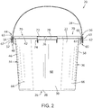
- sanitary pail system 20 includes a pail, body portion, or a body 22 and a bail handle or bail 24 that preferably rotatably and removably cooperates with body 22.
- Body 22 is generally defined by a bottom or base 26 that is defined by a perimeter 28 that extends about the outer edge of the base 26.
- a front wall 30 of body 22 extends in a generally upward direction from a first edge of the perimeter 28 generally perpendicular to the base 26.
- Figs. 6 and 7 are respective top and bottom plan views of body 22, it should be appreciated that the upstanding walls that extend from base 26, or discrete portions thereof, can be oriented to extend in a perpendicular direction from an imaginary plane associated with base 26 or, more preferably, the sidewalls of body 22 extend in a slightly canted of crossing direction relative to a perpendicular direction associated with the imaginary plane defined by base 26 such that base 26 of body 22 has a smaller cross-sectional geometric footprint than a geometric footprint defined by the open or upper end of body 22.
- Figs. 6 and 7 wherein portions of the circumferential sidewalls of body 22 are visible when body 22 is viewed from orientations normal to, either directly above or directly below, body 22.
- body 22 includes a rear wall 32 that is generally opposite front wall 30.
- Rear wall 32 extends from an opposite edge of the perimeter 28 of the base 26 relative to front wall 30 and a first side wall 34 and a second side wall 36 extend upwardly from the base 26 between the front wall 30 and rear wall 32.
- Front wall 30, rear wall 32, and side walls 34, 36 are generally circumferentially continuous and cooperate with base 26 such that body 22 has a substantially continuous and uninterrupted shape.
- base 26 and walls 30, 32, 34, 36 of body 22 form an interior void, fluid cavity, blind opening, or cavity 38 having an open end or open top 40.
- body 22 of sanitation pail system 20 is preferably fluid tight and facilitates the storage and transportation of liquids, such as cleaning and sanitizing liquids or solutions within cavity 38. It should be appreciated that pail system 20 may be used for various objectives associated with cleaning and sanitization objectives associated with placement of a solution in the form of a fluid media, or diluted solution associated therewith, within the fluid cavity defined by body 22.
- Open top 40 of body 22 is defined by a lip 42 that extends preferably continuously in a circumferential manner about an upward directed or upper oriented edge of each of walls 30, 32, 34, 36.
- the lip 42 may be rounded or outwardly curled as to provide a smooth surface that aids in pouring liquids from the cavity 38 when the sanitation pail system 20 is emptied, as will be described in further detail below.
- lip 42 is shown as being oriented entirely within a common imaginary plane, it is appreciated with lip 42 could be shaped such that discrete portions of lip 42 are oriented at elevated or lowered positions relative to other portions of lip.
- the interior facing latitudinal cross section shape of body 22 of the sanitation pail system 20 is approximately hourglass shaped, as indicated by the general shape of the lip 42 ( Figs. 1 and 6 ) and will be described in further detail below.
- the hourglass lateral cross section shape defined by body 22 extends from lip 42 toward base 26 in a manner wherein the area associated with the discrete cross sections decreases as indicted by the inclined walls 30, 32, 34, 36 of body 22.
- Sidewalls 30, 32, and more specifically the radially inward curved portions thereof, define a constriction of the hourglass shape between the inward facing surfaces of sidewalls 30, 32.
- walls 30, 32, 34, 36 extend generally upwardly from the base 26, walls 30, 32, 34, 36 may flair slightly in an outward radial direction as they extend between base 26 towards lip 42.
- Such a consideration provides a construction wherein the outer perimeter of the body 22 is larger at the lip 42 than the perimeter 28 of the base 26 but is maintains the generally hourglass shaped cross section along the height of body 22 between base 26 and lip 42.
- the sanitation pail system 20 is particularly well suited for nesting or stacking with the body 22 of one exemplary sanitation pail system 20 being received within the cavity 38 of an adjacent underlying sanitation pail system 20, which may be repeated for a series of sanitation pail systems 20.
- the body 22 of the sanitation pail system 20 is preferably formed of a molded or thermoformed plastic material. It is appreciated that body 22 of the sanitation pail system 20 may be provided in any number of colors and sizes. In one embodiment of the present invention, body 22 of the sanitation pail system 20 is formed of a color-coded material wherein the color of body 22 distinguishes respective intended uses associated with a discrete pail. For example, a sanitation pail system 20 that is intended for use with a soap and/or cleaning solutions or operations may be formed of one color, such as green, while a sanitation pail system 20 that is intended for use of sanitizing operations and/or to contain sanitizing solutions, may be formed of another color, such as red.
- an outer surface of one or more of the walls 30, 32, 34, 36 of body 22 may include printed or molded additional instructions, warnings, labels or indicia that further identify the intended use or intended contents associated with a given discrete sanitation pail system 20.
- a first boss or bail attachment point 44 extends radially outward from an outer surface 46 of the first side wall 34.
- the first bail attachment point 44 is preferably located proximate or adjacent the lip 42 at approximately a midpoint along the length of the first side wall 34, which is to say equidistance from the front wall 30 and rear wall 32.
- the first bail attachment point 44 includes a bail receiving portion 48, such as a bar or post, about which a first end 52 of the bail 24 can be rotatably attached.
- a bail retaining portion 54 which preferably has a larger cross sectional area than the bail receiving portion 48, thereby preventing the first end 52 of the bail 24 from sliding off or otherwise disengaging the bail receiving portion 48 which allowing bail 24 to rotate uninhibited about pail receiving portion 48.
- the opposing second side wall of the sanitation pail system 20 includes a similar second boss or bail attachment point 56, which extends radially outward from an outer surface 58 of the second side wall 36, which is shown in Figs 1 and 4 .
- the second bail attachment point 56 is preferably located proximate or adjacent the lip 42 at approximately a midpoint along the length of the second side wall 36, which is to say preferably equidistance from the front wall 30 and rear wall 32.
- the second bail attachment point 56 includes a bail receiving portion 60, such as a bar or post, about which a second end 62 of the bail 24 is rotatably attached.
- a bail retaining portion 63 which preferably has a larger cross sectional area than the bail receiving portion 60, thereby preventing the second end 62 of the bail 24 from sliding off or otherwise disengaging the bail receiving portion 60 during usage or pail system 10 for cleaning and sanitation processes and during the customary rotation of bail 24 relative to body 22.
- bail 24 are constructed to be selectively but conveniently removed from discrete bail bosses 44, 46 if desired - such as for cleaning or the like of sanitation pail system 10.
- various entities such as the National Sanitation Foundation (NSF), evaluate equipment intended for commercial applications and provide certifications or status indicators associated with commercial use of the same.
- NSF National Sanitation Foundation
- a view oriented transverse to the axis of rotation of bail 24 relative to body 22 it can be observed that the generally opposite lateral ends 65, 67 of discrete bail bosses 44, 46 which extend between body 22 and the respective bail retaining portions 54, 63 are oriented at different elevations relative to one another.
- respective end 65 associated with bosses 44, 46 are oriented nearer base 26 of body 22 than respective end 67 and whereas respective end 67 is oriented nearer lip 42 than respective end 65 associated with each of bosses or bail attachment points 44, 56.
- an indicia line 69 is preferably provided across the radially outward oriented face of one or more of first and second bail retaining portions 54, 63 and provides a visual indication as to the respective elevations associated with respective ends 65, 67 associated with discrete first and second bail attachment points.
- bail 24 to be conveniently removed from body 22 of sanitation pail system 10 when bail 24 is rotated relative to body 22 to a location below lip 42 and generally aligned with the incline associated with indicia line 69. Subsequent lateral translation of the respective ends 52, 62 of bail 24 relative to their respective bail attachment points 44, 46 in a slightly upward and crossing lateral direction relative to the axis between bail attachment points 44, 56 and relative to body 22 provides disengagement of the respective ends 52, 62 of bail 24 from body 22.
- the inclined crossing orientation between bail 24 and body 22 to effectuate the desired separation therebetween mitigates unintended or undesired separation of bail 24 from body 22 but allows convenient separation therebetween when cleaning or sanitation of the bail 24 and body 22 is desired. Further, the radially outward orientation associated with respective indicia lines 69 allows the user to quickly and conveniently re-associate bail 24 with body 22 for subsequent use of the same.
- an axis defined by a line passing through bail attachment points 44, 56 defines the axis of rotation associate with the rotational association of bail 24 relative to body 22 and is oriented in a crossing directions relative to the pour locations defined by respective corners 64, 66, 80, 82 as disclosed further below.
- front wall 30 of body 22 includes a first corner 64 that is positioned adjacent the first side wall 34 and an opposing second corner 66 that is positioned adjacent the second side wall 36.
- Front wall 30 includes a medial portion 68 that is disposed between the first corner 64 and second corner 66.
- the first corner 64 and second corner 66 are preferably rounded or radially curved along the longitudinal axis of sanitation pail system 20 as shown in Fig. 1 , with the perimeter 28 of the base 26 and the upper lip 42 having a similar curvature.
- the curvature of the first corner 64 and second corner 66 define restricted fluid paths or channels 70 associated with cavity 38 and though which liquid may be poured out of the sanitation pail system 20 in an easily controlled fashion.
- Medial portion 68 of the first wall 30 preferably includes a radially inward directed curvature or bias 72.
- the bias 72 of the medial portion 68 of the first wall 30 is defined by an inwardly projecting arcuate portion. That is to say that the medial portion 68 of the first wall 30 includes a curvature along a longitudinal axis of sanitation pail system 20 that is generally opposite in direction to the curvature of the first corner 64 and second corner 66 associated with first wall 30.
- the bias 72 of the medial portion 68 of the first wall 30 need not be limited to such an arcuate curvature as illustrated in Fig.
- the portion of the perimeter 28 of the base 26 and the upper lip 42 that correspond to the medial portion 68 of the first wall 30 include a generally similar curvature or bias 72. That is to say that medial portion 68 exhibits an inwardly projecting bias 72 from its bottom edge, which is defined by a portion of the perimeter 28 of the base 26, to its upper edge, which is defined by a portion of the upper lip 42.
- a first handle or handle portion 74 extends in a radially outward direction from upper lip 42 of the body 22 of the sanitation pail system 20 at the medial portion 68 of the first wall 30. That is to say that an outwardly extending first handle portion 74 is preferably congruent with the upper lip 42 at the medial portion 68, between the first corner 64 and second corner 66 of the body 22. As shown in Fig. 1 , the first handle portion 74 extends from the upper lip 42 in a cantilevered manner to an outer side wall 76 thereof. A top side 78 of handle portion 74 extends, generally in line with or flush with the upper lip 42, from the upper lip 42 to the outer side wall 76.
- the side wall 76 lies in an imaginary plane defined by line A-A as shown in Figs. 1 and 6 , wherein the outer most edge of the first corner 64 and the second corner 66 are also disposed within the imaginary plane defined by line A-A. That is to say that the outer side wall 76 of the first handle portion 74 does not extend radially outboard of the outer most portion of the first corner 64 and second corner 66 of body 22.
- the outer most portion of the first corner 64 and second corner 66 are defined by a corresponding portion of the upper lip 42; however, it should be understood that the present invention is not so limited.
- the side wall 76 of the first handle may be positioned inboard of the imaginary plane that is defined by the outermost portion of the first corner 64 and second corner 66. That is to say, as a result of the general curvature or bias 72 of medial portion 68 of the first wall 30, the entire first handle portion 74 may not extend to or radially outboard, past an outer most portion or edge of body 22 as defined by an imaginary line A-A that is tangent to the of the first corner 64 and second corner 66.
- opposing rear wall 32 is generally symmetrical with the proceeding discussion of the front wall 30.
- Rear wall 32 defines a third corner 80 of body 22 that is positioned adjacent the second side wall 36 and an opposing fourth corner 82 of body 22 that is adjacent the first side wall 34.
- Rear wall 32 includes a medial portion 84 that is disposed between the third corner 80 and fourth corner 82.
- the third corner 80 and fourth corner 82 are preferably rounded or radially curved along the longitudinal axis of sanitation pail system 20 as shown in Fig. 1 , with the perimeter 28 of the base 26 and the upper lip 42 including a similar curvature to one another and the first corner 64 and second corner 66.
- the curvature of the third corner 80 and fourth corner 82 define restricted fluid paths or channels 86 in the cavity 38 though which liquid may be poured out of the sanitation pail system 20 in an easily controlled fashion.
- the medial portion 84 of rear wall 32 preferably includes an inward curvature or bias 88.
- the bias 88 of the medial portion 84 of the rear wall 32 is defined by an inwardly projecting arcuate portion, similar and opposite to the curvature or bias 72 of the medial portion 68 of the front wall 30. That is to say that the medial portion 84 of the rear wall 32 includes a curvature that is oriented along the longitudinal axis of sanitation pail system 20 that is generally opposite in direction to the curvature of the third corner 80 and fourth corner 82 of the rear wall 32.
- the bias 88 of the medial portion 84 of the rear wall 32 need not be limited to such an arcuate curvature as illustrated in Fig. 1 , and that other curvatures and/or geometries of inwardly projecting medial portion 84 are considered within the scope of the present invention.
- the portion of the perimeter 28 of the base 26 and the portion of upper lip 42 that correspond to the respective medial portions 68, 84 of front wall 30 and rear wall 32 include generally similar curvatures or biases 72, 88. That is to say that the medial portion 84 exhibits an inwardly projecting bias 88 from its bottom edge, which is defined by a portion of the perimeter 28 of the base 26, to its upper edge, which is defined by a portion of the upper lip 42.
- Body 22 of sanitation pail system 20 includes a second handle or handle portion 90 that extends in an outward radial direction from medial portion 84 of body 22 proximate lip 42 associated with rear wall 32.
- Outwardly extending second handle portion 90 is preferably congruent with the upper lip 42 at the medial portion 84, between the third corner 80 and fourth corner 82 of the body 22.
- the second handle portion 90 extends from medial portion 84 proximate upper lip 42 in a generally cantilevered manner and terminates at a free end defined by an outer side wall 92 of second handle portion 90.
- a top side 94 of second handle portion 90 extends generally in-line with or flush with the upper surface of lip 42 to the outer side wall 76.
- side wall 92 is disposed radially inboard of an imaginary line B-B that tangentially intersects each of third corner 80 and the fourth corner 82. That is to say that the outer side wall 92 defined by second handle portion 90 does not extend radially outboard of the outer most portion of the third corner 80 and fourth corner 82.
- the outer most portion of the third corner 80 and fourth corner 82 are defined by a corresponding portion of the upper lip 42; however, it should be understood that the present invention is not so limited.
- the side wall 92 of the second handle portion 90 may be positioned radially inboard of an imaginary plane that is tangential to the outermost portion of the third corner 80 and fourth corner 82 of body 22. That is to say, as a result of the general curvature or bias 88 of medial portion 84 of the rear wall 32, the entire second handle portion 90 may not extend outwardly, past an outer most portion of the third corner 80 and fourth corner 82.
- the body 22 of the sanitation pail system 20 is generally defined by a bottom or base 26 that is defined by a perimeter 28 that extends about the outer edge of the base 26, as is partially shown in Fig. 1 .
- the base 26 of the body 22 is shown in more detail from a top plan view of the sanitation pail system 20.
- the base 26 includes a raised portion 96 that is preferably centrally located relative to the plan view of base 26, a first side portion 98 that is located between the raised portion 96 and the front wall 30, and a second side portion 100 that is located on the opposite the first side portion 98, between the raised portion 96 and the rear wall 32.
- Raised portion 96 associated with base 26 defines a rest associated with supporting a cleaning device or implement in a raised orientation relative to the flanking respective side portions 98, 100 defined by base 26.
- the raised portion 96 includes a cavity facing surface or top surface 104 that is raised relative to at least one of the height or cavity facing or the top surface 106 of the first side portion 98 and the cavity facing or top surface 108 of the second side portion 100, respectively. That is to say that the upper most surface of the raised portion 96 of the body 22 is higher or nearer lip 42 of body 22 than upper most surfaces of the laterally adjacent side portion 98, 100.
- a first side wall 110 extends between the upper surface 106 of the first side portion 98 to the upper surface 104 of the raised portion 96, while a second side wall 112 extends between the upper surface 108 of the second side portion 100 and the upper surface 104 of the raised portion 96, on the side opposite the first side wall 110.
- first and second side walls 110, 112 may be curved to prevent the debris or small solid waste from becoming entrapped along the edge; however, it should be understood that the present invention is in no way so limited and other transitional contours are considered within the scope of the present invention.
- a series of baffles 114 may extend over the top surfaces 106, 108 of the respective first side portion 98 and second side portion 100, between the corresponding front or rear wall 30, 32 to the raised portion 96.
- the spaced apart baffles 114 are positioned along the top surface 106, 108 of the base 26 of the body 22, and define individual wells 116 that are separated by adjacent baffles 114.
- the raised height of the baffles 114, relative to the portion of the corresponding top surface 106, 108 that form the wells 116 inhibits water of fluid movement within the discrete wells 116. Resultantly, debris or sediment that has collected in the sanitation pail system 20 settles toward the corresponding top surface 106, 108 via gravity, and is received in the wells 116 where its movement will be restricted by contacting the bordering baffles 114, side walls 110, 112 and or wall 30, 32. Such restricted movement of the debris or sediment within the wells 116 inhibits its potential for resuspension in the washing fluid, or contact with the washcloth, sponge, or other cleaning device or implement.
- the top surface 104 of the raised portion 96 of the bottom or base 26, as well as the top most edge of the series of baffles 114 provides a relatively higher surface for the washcloth or rag to rest upon, as compared to the corresponding cavity facing or top surface 106, 108 defined the wells 116. That is to say in use, as smaller debris or sediment that has collected in the sanitation pail system 20 is pulled down into the wells 116 via gravity, the washcloth or rag will remain relative higher as it is pulled down to rest upon the top surface 104 of the raised portion 96.
- the washcloth or rag rests on a surface that is not occupied by debris or sediment, thereby preventing such debris or sediment from being pulled back out of the sanitation pail system 20 during rinsing or removal of the cleaning device from pail system 20.
- the top surface 104 of the central portion may also be crowned or angled, which will further facilitate separation of debris or sediment from the treatment solution and direct the same into the adjacent wells 116.
- the raised portion 96 of the bottom 26 has a generally diamond shape, in which the side walls 110, 112 are not linear, but rather each include an obtuse angle 118 defined by side walls 110, 112 generally at a midline portion of each side wall 110, 112. That is to say each of the side walls 110, 112 are divided by a relatively centrally located angle 118, which separates each of the two side walls 110, 112 into two wall segments 120 of approximately equal length. As shown in Fig.
- each of the respective linear wall segments 120 is angled approximately between 30° and 60° to a corresponding side wall 34, 36 of the body 22, which is to say that each respective linear wall segment 120 is angled approximately perpendicular to a corresponding corner 64, 66, 80, 82.
- the underside of an opposing linear wall segments 120 may be grasped by a user to facilitate tipping the sanitation pail system 20 when fluid is being poured from a given corner 64, 66, 80, 82.
- Figs. 8 and 9 illustrate one configuration in which the sanitation pail system 20 has been tilted such that a fluid may be poured from the restricted fluid paths or channel 70 formed at corner 64. As shown in Figs.
- the opposing linear wall segment 120 is positioned at a height greater than the height of corner 64, facilitated by a user (not shown) grasping and raising the opposing linear wall segments 120 with one hand while grasping the bail 24 in the other hand, about which the body 22 rotates.
- Figs. 7-9 the underside of the base 26 of the body 22 is shown, where the bottom surface 122 of the raised portion 96 of base 26 is shown recessed relative to the bottom surface 124 of the first side portion 96 and the bottom surface 126 of the second side portion 100, consistent with the preceding discussion.
- the underside of the linear wall segments 120 of the side walls 110, 112 are further shown relative to the corresponding corners 64, 66, 80, 82 of the body 22, where they may define handles used for tipping and emptying the sanitation pail system 20, as described above.
- pail system 10 is configured to mitigate overreaching or extending associated with transport and pouring activities and is constructed to provide a more comfortable user interaction therewith and in a manner that can accommodate discrete preferences of discrete users of sanitation pail system 10.
- the bottom surface 124 of the first side portion 96 and the bottom surface 126 of the second side portion 100 also defining raised feet 128 upon which the sanitation pail system 20 may be placed on a support surface, with the opposing lateral feet 128 being separated from one another by a recess 130 that extends from side wall 34 to side wall 36 along the bottom surface 124 of the central portion 96, as well as the convenient removability associated with the rotational interaction of bail 24 with body 22, provides a sanitation pail system 10 whose own sanitation can be conveniently and expeditiously maintained.
- sanitation pail system 20 may vary greatly to accommodate the various volumes of the cavity 38 within the body 22 of the respective sanitation pail system 20. That is to say that the sanitation pail system 20, described above and shown in Figs. 1-9 may be provided with a volume or cavity 38 that is sufficient to retain approximately between 1 fluid quart and 25 fluid quarts, and more preferably between approximately between 3 fluid quarts and 15 fluid quarts, all of which are considered will within the scope of the present invention.
Landscapes
- Engineering & Computer Science (AREA)
- Mechanical Engineering (AREA)
- Food Science & Technology (AREA)
- Details Of Rigid Or Semi-Rigid Containers (AREA)
Applications Claiming Priority (1)
| Application Number | Priority Date | Filing Date | Title |
|---|---|---|---|
| US15/997,088 US10932624B2 (en) | 2018-06-04 | 2018-06-04 | Sanitation pail with pour and sediment collection features |
Publications (1)
| Publication Number | Publication Date |
|---|---|
| EP3578090A1 true EP3578090A1 (de) | 2019-12-11 |
Family
ID=66998058
Family Applications (1)
| Application Number | Title | Priority Date | Filing Date |
|---|---|---|---|
| EP19178120.2A Pending EP3578090A1 (de) | 2018-06-04 | 2019-06-04 | Sanitäreimer mit giess- und sedimentsammelvorrichtungen |
Country Status (4)
| Country | Link |
|---|---|
| US (1) | US10932624B2 (de) |
| EP (1) | EP3578090A1 (de) |
| CA (1) | CA3044990A1 (de) |
| MX (1) | MX2019006507A (de) |
Families Citing this family (3)
| Publication number | Priority date | Publication date | Assignee | Title |
|---|---|---|---|---|
| USD927815S1 (en) * | 2020-03-02 | 2021-08-10 | Swimc Llc | Coating material container |
| USD1118074S1 (en) * | 2023-02-16 | 2026-03-10 | Fiskars Finland Oy Ab | Caddy |
| USD1110638S1 (en) | 2023-05-16 | 2026-01-27 | Swimc Llc | Coating material container |
Citations (5)
| Publication number | Priority date | Publication date | Assignee | Title |
|---|---|---|---|---|
| US2896809A (en) * | 1956-11-01 | 1959-07-28 | Parke H Metzger | Nesting pail |
| US5971199A (en) * | 1998-01-12 | 1999-10-26 | Amway Corporation | Soil separation apparatus |
| US20110000046A1 (en) * | 2009-07-01 | 2011-01-06 | Chen Yung-Hua | Non-stepping wringer bucket |
| WO2014022888A1 (en) * | 2012-08-08 | 2014-02-13 | E.D. Oates Pty Ltd | Mop bucket |
| EP2774526A2 (de) * | 2013-03-08 | 2014-09-10 | Vale Mill (Rochdale) Limited | Schrubber-Eimer-System |
Family Cites Families (31)
| Publication number | Priority date | Publication date | Assignee | Title |
|---|---|---|---|---|
| US1517164A (en) | 1922-03-30 | 1924-11-25 | Melchor F Lear | Scrubbing pail |
| US2671239A (en) | 1948-10-28 | 1954-03-09 | John A Wisner | Combined rinsing and detergent container |
| US2712668A (en) | 1951-06-18 | 1955-07-12 | Hazel L Thiele | Scrub bucket |
| US3338468A (en) | 1965-05-24 | 1967-08-29 | Banner Metals Inc | Receptacle |
| US3384263A (en) * | 1966-12-22 | 1968-05-21 | Bernstein Daniel | Container and cover assembly |
| US3829926A (en) | 1972-10-05 | 1974-08-20 | Action Inc | Paint bucket |
| US4941586A (en) * | 1989-01-18 | 1990-07-17 | Sarvis Oy | Container |
| GB2229987B (en) | 1989-03-21 | 1992-12-16 | Crown Berger Europ | Containers for liquids |
| US5119571A (en) | 1990-08-01 | 1992-06-09 | Richard Beasley | Dehydration apparatus and process of dehydration |
| US5412818A (en) | 1994-07-19 | 1995-05-09 | Chen; Kai-Jung | Washing-up sink with a washplate |
| US6095333A (en) * | 1995-02-23 | 2000-08-01 | Ritvik Holdings Inc. | Child safety bucket |
| NL1000422C2 (nl) * | 1995-05-23 | 1996-11-25 | Wavin Bv | Rechthoekige bak met deksel. |
| USD386866S (en) * | 1996-04-17 | 1997-11-25 | Rubbermaid Incorporated | Refuse container base |
| USD387530S (en) * | 1996-04-26 | 1997-12-09 | Rubbermaid Incorporated | Receptacle container |
| US5715968A (en) * | 1996-09-27 | 1998-02-10 | Fink; Stacey M. | Hand carried shopping basket |
| US5813567A (en) * | 1996-11-12 | 1998-09-29 | Mangano; Joy | Mop bucket having integral mop stabilizing structure |
| US6105813A (en) | 1997-06-25 | 2000-08-22 | Roller Coater, Inc. | Multi purpose paint bucket |
| US6062389A (en) | 1998-06-10 | 2000-05-16 | Kenmont, Llc | Dual bucket assembly |
| US6138863A (en) | 1999-01-29 | 2000-10-31 | Rehrig Pacific Company | Multipurpose container |
| US6293692B1 (en) | 1999-11-05 | 2001-09-25 | M. William Bowsher | Multipurpose container structure |
| US6761271B1 (en) | 2001-06-25 | 2004-07-13 | Lynn J. Cresswell | Rinse screen for a water bucket |
| USD489286S1 (en) * | 2003-01-08 | 2004-05-04 | Mark A. Rogers | Plant pot |
| MXPA06012795A (es) * | 2004-05-05 | 2007-02-15 | Rubbermaid Commercial Products | Almohadillas de trapeador codificadas por color y metodo para codificar por color las mismas. |
| US7410074B1 (en) | 2004-09-02 | 2008-08-12 | Robert Brunning | Paint bucket |
| US20070119854A1 (en) | 2005-11-28 | 2007-05-31 | Rittmann Jean V | Paint bucket |
| US7938286B2 (en) * | 2007-02-13 | 2011-05-10 | Gateway Plastics, Inc. | Container system |
| DE102009043686B4 (de) | 2009-10-01 | 2013-10-10 | Carl Freudenberg Kg | Wischeimer |
| AU2010340293A1 (en) * | 2010-01-06 | 2012-08-02 | Spin Free L.L.C. | Method and apparatus for stabilizing a mixing bucket |
| US9957078B2 (en) * | 2013-05-22 | 2018-05-01 | Macro Plastics, Inc. | Shipping container |
| US10077138B2 (en) * | 2015-02-18 | 2018-09-18 | San Jamar, Inc. | Handled container |
| USD778519S1 (en) | 2015-03-26 | 2017-02-07 | Bway Corporation | Container with integrated handles |
-
2018
- 2018-06-04 US US15/997,088 patent/US10932624B2/en active Active
-
2019
- 2019-06-03 CA CA3044990A patent/CA3044990A1/en active Pending
- 2019-06-04 MX MX2019006507A patent/MX2019006507A/es unknown
- 2019-06-04 EP EP19178120.2A patent/EP3578090A1/de active Pending
Patent Citations (5)
| Publication number | Priority date | Publication date | Assignee | Title |
|---|---|---|---|---|
| US2896809A (en) * | 1956-11-01 | 1959-07-28 | Parke H Metzger | Nesting pail |
| US5971199A (en) * | 1998-01-12 | 1999-10-26 | Amway Corporation | Soil separation apparatus |
| US20110000046A1 (en) * | 2009-07-01 | 2011-01-06 | Chen Yung-Hua | Non-stepping wringer bucket |
| WO2014022888A1 (en) * | 2012-08-08 | 2014-02-13 | E.D. Oates Pty Ltd | Mop bucket |
| EP2774526A2 (de) * | 2013-03-08 | 2014-09-10 | Vale Mill (Rochdale) Limited | Schrubber-Eimer-System |
Also Published As
| Publication number | Publication date |
|---|---|
| US10932624B2 (en) | 2021-03-02 |
| CA3044990A1 (en) | 2019-12-04 |
| MX2019006507A (es) | 2020-01-13 |
| US20190365159A1 (en) | 2019-12-05 |
Similar Documents
| Publication | Publication Date | Title |
|---|---|---|
| US10077138B2 (en) | Handled container | |
| EP3578090A1 (de) | Sanitäreimer mit giess- und sedimentsammelvorrichtungen | |
| US5419454A (en) | Mixing bowl | |
| CN1226007C (zh) | 复合碗 | |
| US6062389A (en) | Dual bucket assembly | |
| US6739363B2 (en) | Funnel set | |
| EP0759280A2 (de) | Behälter zum Handmischen | |
| US5615447A (en) | Portable cleaning container having foot activated drain | |
| US8636171B1 (en) | Dripless container | |
| KR0155209B1 (ko) | 싱크대 주변 용기 | |
| CN107529933B (zh) | 拖把桶 | |
| AU2001266995A1 (en) | Composite bowl | |
| AU2016348623B2 (en) | Bucket | |
| GB2606430A (en) | Nesting paint tray and paint bucket system, paint tray, and paint tray liner | |
| US20140251890A1 (en) | Colander-bowl assembly | |
| WO2013163548A1 (en) | Ice handling container | |
| US7267308B1 (en) | Kitchen utensil and pot lid holder | |
| WO2007141775A2 (en) | Mop bucket | |
| US20070295723A1 (en) | Vessel with indicia and caddy | |
| US7121415B1 (en) | Utensil receptacle | |
| GB2491253A (en) | A domestic washing bowl with magnetic means of holding a drainage closure open or shut. | |
| US20050211707A1 (en) | Vessel with indicia and caddy | |
| US6827224B2 (en) | Food liquid strainer for cooking | |
| WO2008007154A1 (en) | Bowl | |
| CA2676631A1 (en) | Multi-handled jerry can |
Legal Events
| Date | Code | Title | Description |
|---|---|---|---|
| PUAI | Public reference made under article 153(3) epc to a published international application that has entered the european phase |
Free format text: ORIGINAL CODE: 0009012 |
|
| STAA | Information on the status of an ep patent application or granted ep patent |
Free format text: STATUS: THE APPLICATION HAS BEEN PUBLISHED |
|
| AK | Designated contracting states |
Kind code of ref document: A1 Designated state(s): AL AT BE BG CH CY CZ DE DK EE ES FI FR GB GR HR HU IE IS IT LI LT LU LV MC MK MT NL NO PL PT RO RS SE SI SK SM TR |
|
| AX | Request for extension of the european patent |
Extension state: BA ME |
|
| STAA | Information on the status of an ep patent application or granted ep patent |
Free format text: STATUS: REQUEST FOR EXAMINATION WAS MADE |
|
| 17P | Request for examination filed |
Effective date: 20200609 |
|
| RBV | Designated contracting states (corrected) |
Designated state(s): AL AT BE BG CH CY CZ DE DK EE ES FI FR GB GR HR HU IE IS IT LI LT LU LV MC MK MT NL NO PL PT RO RS SE SI SK SM TR |
|
| STAA | Information on the status of an ep patent application or granted ep patent |
Free format text: STATUS: EXAMINATION IS IN PROGRESS |
|
| 17Q | First examination report despatched |
Effective date: 20210406 |
|
| GRAP | Despatch of communication of intention to grant a patent |
Free format text: ORIGINAL CODE: EPIDOSNIGR1 |
|
| STAA | Information on the status of an ep patent application or granted ep patent |
Free format text: STATUS: GRANT OF PATENT IS INTENDED |
|
| RIC1 | Information provided on ipc code assigned before grant |
Ipc: A47J 47/18 20060101AFI20250808BHEP Ipc: B65D 21/02 20060101ALN20250808BHEP Ipc: B65D 25/28 20060101ALN20250808BHEP Ipc: B65D 25/32 20060101ALN20250808BHEP |
|
| INTG | Intention to grant announced |
Effective date: 20250902 |
|
| STAA | Information on the status of an ep patent application or granted ep patent |
Free format text: STATUS: THE APPLICATION IS DEEMED TO BE WITHDRAWN |