EP3578149A1 - Dispositif de guidage d'un appareil de production d'articles sanitaires pour appliquer un fil et procédé associé - Google Patents
Dispositif de guidage d'un appareil de production d'articles sanitaires pour appliquer un fil et procédé associé Download PDFInfo
- Publication number
- EP3578149A1 EP3578149A1 EP19177850.5A EP19177850A EP3578149A1 EP 3578149 A1 EP3578149 A1 EP 3578149A1 EP 19177850 A EP19177850 A EP 19177850A EP 3578149 A1 EP3578149 A1 EP 3578149A1
- Authority
- EP
- European Patent Office
- Prior art keywords
- thread
- linear direction
- along
- guiding device
- magnetic field
- Prior art date
- Legal status (The legal status is an assumption and is not a legal conclusion. Google has not performed a legal analysis and makes no representation as to the accuracy of the status listed.)
- Withdrawn
Links
- 238000000034 method Methods 0.000 title claims abstract description 21
- 239000000758 substrate Substances 0.000 claims abstract description 28
- 230000005291 magnetic effect Effects 0.000 claims description 100
- 125000006850 spacer group Chemical group 0.000 claims description 49
- 238000001816 cooling Methods 0.000 claims description 9
- 239000012809 cooling fluid Substances 0.000 claims description 6
- 230000005674 electromagnetic induction Effects 0.000 claims description 3
- 238000011109 contamination Methods 0.000 abstract description 6
- 238000005265 energy consumption Methods 0.000 abstract description 2
- 230000009471 action Effects 0.000 description 13
- 239000000463 material Substances 0.000 description 7
- 230000001133 acceleration Effects 0.000 description 5
- 239000000356 contaminant Substances 0.000 description 5
- 238000004804 winding Methods 0.000 description 5
- XEEYBQQBJWHFJM-UHFFFAOYSA-N Iron Chemical compound [Fe] XEEYBQQBJWHFJM-UHFFFAOYSA-N 0.000 description 4
- 238000012423 maintenance Methods 0.000 description 4
- 238000005461 lubrication Methods 0.000 description 3
- 230000008901 benefit Effects 0.000 description 2
- 239000002131 composite material Substances 0.000 description 2
- 239000013013 elastic material Substances 0.000 description 2
- 239000004744 fabric Substances 0.000 description 2
- 229910052742 iron Inorganic materials 0.000 description 2
- 239000000314 lubricant Substances 0.000 description 2
- 238000004519 manufacturing process Methods 0.000 description 2
- 239000004745 nonwoven fabric Substances 0.000 description 2
- 230000009467 reduction Effects 0.000 description 2
- 230000000717 retained effect Effects 0.000 description 2
- ZOXJGFHDIHLPTG-UHFFFAOYSA-N Boron Chemical compound [B] ZOXJGFHDIHLPTG-UHFFFAOYSA-N 0.000 description 1
- 229920003043 Cellulose fiber Polymers 0.000 description 1
- 229920001780 ECTFE Polymers 0.000 description 1
- 239000004593 Epoxy Substances 0.000 description 1
- 206010021639 Incontinence Diseases 0.000 description 1
- 229910052779 Neodymium Inorganic materials 0.000 description 1
- 239000003831 antifriction material Substances 0.000 description 1
- 230000004888 barrier function Effects 0.000 description 1
- 210000001124 body fluid Anatomy 0.000 description 1
- 239000010839 body fluid Substances 0.000 description 1
- 229910052796 boron Inorganic materials 0.000 description 1
- 229920002678 cellulose Polymers 0.000 description 1
- 239000001913 cellulose Substances 0.000 description 1
- 230000001419 dependent effect Effects 0.000 description 1
- 238000013461 design Methods 0.000 description 1
- 238000009826 distribution Methods 0.000 description 1
- 239000000428 dust Substances 0.000 description 1
- 230000000694 effects Effects 0.000 description 1
- 230000005294 ferromagnetic effect Effects 0.000 description 1
- 239000012530 fluid Substances 0.000 description 1
- 239000011521 glass Substances 0.000 description 1
- 239000003292 glue Substances 0.000 description 1
- 230000001939 inductive effect Effects 0.000 description 1
- 239000011810 insulating material Substances 0.000 description 1
- 230000003993 interaction Effects 0.000 description 1
- 230000001050 lubricating effect Effects 0.000 description 1
- 238000012986 modification Methods 0.000 description 1
- 230000004048 modification Effects 0.000 description 1
- QEFYFXOXNSNQGX-UHFFFAOYSA-N neodymium atom Chemical compound [Nd] QEFYFXOXNSNQGX-UHFFFAOYSA-N 0.000 description 1
- 230000036316 preload Effects 0.000 description 1
- 238000005096 rolling process Methods 0.000 description 1
- 238000000926 separation method Methods 0.000 description 1
- 230000006641 stabilisation Effects 0.000 description 1
- 238000011105 stabilization Methods 0.000 description 1
- 230000002195 synergetic effect Effects 0.000 description 1
- 238000012546 transfer Methods 0.000 description 1
- 238000013519 translation Methods 0.000 description 1
- 238000003466 welding Methods 0.000 description 1
Images
Classifications
-
- A—HUMAN NECESSITIES
- A61—MEDICAL OR VETERINARY SCIENCE; HYGIENE
- A61F—FILTERS IMPLANTABLE INTO BLOOD VESSELS; PROSTHESES; DEVICES PROVIDING PATENCY TO, OR PREVENTING COLLAPSING OF, TUBULAR STRUCTURES OF THE BODY, e.g. STENTS; ORTHOPAEDIC, NURSING OR CONTRACEPTIVE DEVICES; FOMENTATION; TREATMENT OR PROTECTION OF EYES OR EARS; BANDAGES, DRESSINGS OR ABSORBENT PADS; FIRST-AID KITS
- A61F13/00—Bandages or dressings; Absorbent pads
- A61F13/15—Absorbent pads, e.g. sanitary towels, swabs or tampons for external or internal application to the body; Supporting or fastening means therefor; Tampon applicators
- A61F13/15577—Apparatus or processes for manufacturing
- A61F13/15585—Apparatus or processes for manufacturing of babies' napkins, e.g. diapers
- A61F13/15593—Apparatus or processes for manufacturing of babies' napkins, e.g. diapers having elastic ribbons fixed thereto; Devices for applying the ribbons
-
- A—HUMAN NECESSITIES
- A61—MEDICAL OR VETERINARY SCIENCE; HYGIENE
- A61F—FILTERS IMPLANTABLE INTO BLOOD VESSELS; PROSTHESES; DEVICES PROVIDING PATENCY TO, OR PREVENTING COLLAPSING OF, TUBULAR STRUCTURES OF THE BODY, e.g. STENTS; ORTHOPAEDIC, NURSING OR CONTRACEPTIVE DEVICES; FOMENTATION; TREATMENT OR PROTECTION OF EYES OR EARS; BANDAGES, DRESSINGS OR ABSORBENT PADS; FIRST-AID KITS
- A61F13/00—Bandages or dressings; Absorbent pads
- A61F13/15—Absorbent pads, e.g. sanitary towels, swabs or tampons for external or internal application to the body; Supporting or fastening means therefor; Tampon applicators
- A61F13/15577—Apparatus or processes for manufacturing
- A61F13/15772—Control
-
- A—HUMAN NECESSITIES
- A61—MEDICAL OR VETERINARY SCIENCE; HYGIENE
- A61F—FILTERS IMPLANTABLE INTO BLOOD VESSELS; PROSTHESES; DEVICES PROVIDING PATENCY TO, OR PREVENTING COLLAPSING OF, TUBULAR STRUCTURES OF THE BODY, e.g. STENTS; ORTHOPAEDIC, NURSING OR CONTRACEPTIVE DEVICES; FOMENTATION; TREATMENT OR PROTECTION OF EYES OR EARS; BANDAGES, DRESSINGS OR ABSORBENT PADS; FIRST-AID KITS
- A61F13/00—Bandages or dressings; Absorbent pads
- A61F13/15—Absorbent pads, e.g. sanitary towels, swabs or tampons for external or internal application to the body; Supporting or fastening means therefor; Tampon applicators
- A61F13/15577—Apparatus or processes for manufacturing
- A61F13/15617—Making absorbent pads from fibres or pulverulent material with or without treatment of the fibres
- A61F13/1565—Making absorbent pads from fibres or pulverulent material with or without treatment of the fibres by depositing continuous layers of fibrous material between webs, e.g. wrapping layers of fibrous material
-
- B—PERFORMING OPERATIONS; TRANSPORTING
- B65—CONVEYING; PACKING; STORING; HANDLING THIN OR FILAMENTARY MATERIAL
- B65H—HANDLING THIN OR FILAMENTARY MATERIAL, e.g. SHEETS, WEBS, CABLES
- B65H57/00—Guides for filamentary materials; Supports therefor
- B65H57/28—Reciprocating or oscillating guides
Definitions
- Embodiments of the present invention relate to a guiding device of an apparatus for producing sanitary articles for applying a thread onto a substrate intended for producing these sanitary articles such as, for example, diapers, pull-ups, incontinence pads, sanitary napkins, or other articles designed to absorb body fluids.
- Embodiments of the present invention relate to a guiding device of an apparatus for producing sanitary articles configured to apply elastic threads onto a substrate such as, for example, a continuous web material, a continuous composite sheet, or a discrete component.
- Embodiments of the present invention also relate to a method utilizing one or more guiding devices of an apparatus for producing sanitary articles for applying threads onto a substrate intended for producing sanitary articles.
- sanitary articles made with non-elastic materials which, in relation to the specific articles to be made and to the desired wearability to be achieved, can be rendered elastic, for example, by trapping elastic threads between them.
- a typical example of applying elastic threads to a diaper is that of the waist band, or of the leg cuffs, in which pleated regions are made by means of these elastic threads, which provide a certain extensibility to the material.
- Entrapment of pre-tensioned elastic threads between two sheets of non-elastic materials for example a non-woven fabric is known by locally fixing the sheets together and/or the elastic threads tensioned to the sheets so as to locally constrain the elastic threads along a pattern of entrapment.
- the elastic thread is guided along a specific path adjusting the feeding speed during its application onto the substrate.
- Some guiding devices comprise a linear guide defining a linear direction and a carriage provided with a thread-carrying tool which is configured to move on the linear guide in relation to the specific entrapment pattern to be achieved.
- the carriage makes multiple changes of direction that significantly wear out both the wheels, or balls, of the carriage, and the surface of the linear guide, requiring frequent maintenance and/or lubrication.
- the thread is typically supplied to the substrate incorrectly, making the resulting sanitary articles non-conformant to the required specifications.
- EP-A-1.148.016 (EP'016) describes an apparatus for winding a thread onto a reel, in which the apparatus consists of a carriage movable on a magnetic guide and is configured to reach speeds from 2 m/s to 6 m/s.
- Document EP'016 describes and addresses the problem of changing direction of the movable carriage and, in particular, proposes the use of a control unit configured for controlling the speed of the movable carriage during the inversion.
- the apparatuses for winding thread on reels envisage that the movable carriage can perform repeated movements along a linear direction between two fixed and spaced-apart end positions of a limited length.
- the thread-guiding devices In the field of apparatuses for producing sanitary articles, it is known that the thread-guiding devices must convey the threads so as to produce various and different entrapment patterns quickly in order to produce different formats of sanitary articles.
- the movable carriage In the field of sanitary articles, it is required that the movable carriage is moved with a linear stroke even greater than 30 cm and with speeds and accelerations equal to if not greater than those of the field of apparatus for producing reels.
- Document DE-A-10.2013.225653 (DE'653) describes an apparatus for winding a thread onto a reel consisting of a movable carriage coupled to a magnetic beam.
- the movable carriage is kept spaced apart from the magnetic beam by means of a permanent magnetic field obtained by the interaction between a plurality of permanent magnets arranged on the movable carriage and the magnetic beam itself.
- the apparatus described in DE'653 also comprises aerostatic brakes placed at the ends of the magnetic beam and oriented towards the movable carriage. These aerostatic brakes are configured to slow down the movable carriage when the carriage reaches the ends so that it does not hit against the ends.
- DE'653 also describes the possibility of using aerostatic brakes as a means of moving the movable carriage which, under the thrusting action of compressed air jets from the aerostatic brakes, can move along the magnetic beam.
- the rotating element of WO'663 is positioned spaced apart from a plane and is moved by means of a magnetic movement assembly.
- the rotating element is provided with an inductive circuit which, when powered, couples with the magnetic field generated by magnets installed on the plane.
- this known solution has the further problem that the end that guides the thread towards the reel follows a curvilinear path and, even if the rotating element is spaced apart from the plane, it can bend towards the plane in relation to the direction of the thread and its elasticity.
- the known solutions cannot be used in apparatuses for producing sanitary articles that require speeds of up to 10 m/s, with accelerations at full speed even higher than 230 m/s 2 and with strokes even greater than 30 cm.
- the need has arisen to provide a guiding device of an apparatus for producing sanitary articles which, in addition to ensuring high standards of stability, precision and performance, is able to overcome the problems connected to contamination and those related to wear of the sliding parts.
- One object of the present invention is to provide a guiding device capable of overcoming the problems related to wear, which does not require frequent maintenance and lubrication, and which - at the same time - allows the thread to be supplied on the substrate in a reproducible and precise manner.
- Another object of the present invention is to provide a guiding device capable of supplying the thread in a stable, controlled and high-speed manner.
- Another object of the present invention is to provide a guiding device capable of overcoming the problems related to contamination, while eliminating the problems relating to wear and lubrication.
- the present invention relates to a guiding device of an apparatus for producing sanitary articles for applying at least one thread onto a substrate intended to produce these sanitary articles, which comprises a first body movable along a linear direction and configured to guide the thread, and at least one second body fixed with respect to the first body.
- the substrate may comprise a continuous web or other material.
- the guiding device also comprises a magnetic movement assembly associated with the first body, and with the at least one second body, for moving the first body along the linear direction by means of a magnetic force. Thanks to the action of a spacer assembly, a gap is formed between the first body and the at least one second body, also considering any elements associated with them.
- the magnetic movement assembly comprises a plurality of magnets, placed on the first body, and means for generating a variable magnetic field, placed on the at least one second body, in which the variable magnetic field is such as to cooperate, in use, with at least part of the magnets to move the first body along the linear direction by magnetic force.
- the guiding device comprises a spacer assembly configured to space the first body apart from the at least one second body to form a gap between them by means of an air cushion.
- this solution hinders the access of the cellulose fibers and/or other contaminants into the gap, as well as their deposit on the surfaces defining the gap.
- This solution does not require the use of lubricants and, furthermore, significantly reduces the wear of the moving parts, since there are no rolling elements such as, for example, balls, rollers, or other elements, in contact with the first body and/or with the at least one second body.
- the presence of the air cushion also makes it possible to further speed up the movement of the first body along the linear direction, while at the same time ensuring high stability and precision to apply the thread onto the substrate correctly.
- the spacer assembly may comprise a plurality of aerostatic spacer elements each configured to generate a respective air cushion in order to locally distance the first body from the at least one second body.
- the aerostatic spacer elements can be placed on the at least one second body on the sides of the magnetic movement unit.
- the spacer assembly may comprise at least one magnetic spacer element configured to locally distance the first body from the at least one second body by means of another magnetic force.
- the guiding device may comprise at least two second bodies between which the first body is interposed, wherein each of the at least two second bodies is provided with respective means for generating a respective variable magnetic field.
- the ratio between the respective lengths along the linear direction of the first body and of the second body can be greater than 1.
- the guiding device may comprise at least one management and control unit configured to modulate the variable magnetic field generated by the means, by means of a control signal sent by the management and control unit to the means.
- the guiding device may comprise at least two management and control units, each configured to modulate the respective variable magnetic field generated by the respective means of the at least two second bodies, by means of a respective control signal sent by the management and control unit to the respective means.
- the guiding device may comprise a support member connected to the first body and configured to connect a tool to carry the thread, in which the support member extends, at least in part, out of the at least a second body.
- the guiding device may comprise a cooling unit configured to cool at least the first body by means of a cooling fluid.
- the present invention also relates to a method for applying a thread onto a substrate intended to produce sanitary articles.
- the method envisages: associating the thread with a first body movable along a linear direction; spacing the first body apart from the at least one second body fixed with respect to the first body by means of an air cushion; and moving the first body along the linear direction by a magnetic force so as to guide the thread to apply it on the substrate.
- the movement of the first body is obtained by means of a magnetic movement assembly comprising a plurality of magnets, placed on the first body, and means for generating a variable magnetic field, placed on the at least one second body.
- the method may envisage generating electrical energy by electromagnetic induction, while the first body decelerates, and feeding an apparatus with said generated electric energy.
- the method may envisage setting a desired timetable defining the position of the first body along the linear direction in relation to time, and for moving the first body according to the set timetable.
- the method may envisage modulating the movement of the first body in relation to the elasticity of the thread and to the instantaneous position of the first body along the linear direction.
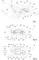
- Embodiments described herein, with reference to the figures, refer to a guiding device 10 of an apparatus for producing sanitary articles for applying at least one thread 11 onto a substrate 12 intended to produce these sanitary articles.
- the substrate 12 can be a continuous web, a discrete element, or another component of a sanitary article.
- the guiding device 10 allows application of an elastic thread 11 between two substrates 12 of flexible but not elastic fabric and to trap it between them so as to render the composite fabric elastic.
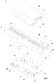
- the guiding device 10 comprises a first body 13 movable along a linear direction X and configured to guide the thread 11, and at least one second body 14 fixed with respect to the first body 13.
- the first body 13 is configured to carry a thread 11 supplied thereto, which is guided towards the substrate 12 by moving the first body 13 itself.
- the guiding device 10 also comprises a magnetic movement assembly 15 associated with the first body and with the at least one second body for moving the first body along the linear direction by means of a magnetic force.
- the guiding device 10 comprises a spacer assembly 16 configured to space the first body 13 apart from the at least one second body 14 by means of an air cushion.
- a gap 17 is formed between the first body 13 and the at least one second body 14, also considering any elements associated with them.
- the possible elements associated with the first body 13 and/or with the at least one second body 14 may comprise magnets 18, means 19 for generating a variable magnetic field, the aerostatic spacer elements 27, 127, or other elements.
- the minimum width of the gap 17 can be between 1 ⁇ m and 20 ⁇ m. According to possible embodiments, the minimum width of the gap 17 can be between 5 ⁇ m and 15 ⁇ m.
- the magnetic drive assembly 15 may comprise a plurality of magnets 18 and means 19 for generating a variable magnetic field so as to cooperate, in use, with at least part of the magnets 18 to move the first body 13 along the linear direction X.
- This embodiment makes it possible to control the movement of the first body 13 through the means 19 for generating a variable magnetic field without the need to also intervene directly on the magnets 18, whether the magnets are configured to generate a variable magnetic field, or if they are electromagnets.
- the magnetic movement assembly 15 may comprise a plurality of magnets 18, placed on the first body 13, and means 19 for generating a variable magnetic field, placed on the at least one second body 14.
- the guiding device 10 may comprise at least one management and control unit 31 configured to modulate the variable magnetic field generated by the means 19, by means of a control signal sent by said management and control unit 31 to the means 19.
- the management and control unit 31 it is possible to make the guiding device 10 flexible, in other words able to move the first body 13 in accordance with the specific production requirements. This allows entrapment patterns of the threads 11 to be created in the substrates 12 and therefore enables production of various and different types of sanitary articles.
- the first body 13 By modulating the variable magnetic field in the desired manner, the first body 13 performs various movements in relation to the sanitary article to be produced.
- the possibility of also being able to modify the movement of the first body 13 during feeding of the thread 11 makes it possible to manage the pull of the thread in relation to the elasticity of the thread 11 and to the instantaneous position of the first body 13 along the linear direction X.
- modulating the variable magnetic field to modify - in real time - the movement of the first body 13 to compensate for the pulling effects of the thread 11 can be determined once the linear direction X has been defined with respect to the application point of the thread 11 on the substrate 12.
- the magnets 18 can be permanent magnets such as, for example, magnets comprising iron, or other magnetic elements.
- the magnets 18 may comprise neodymium, iron and boron which, when combined, exhibit high energy densities and operating temperatures.
- the means 19 for generating a variable magnetic field may comprise one or more reels possibly coupled to ferromagnetic cores which allow generation of a variable magnetic field in relation to the electric current that is supplied to them.
- These reels can be spatially positioned so as to generate - each time - a magnetic field having the desired distribution of intensity and direction.
- the means 19 for generating a variable magnetic field can be magnetic actuators.
- the first body 13 is moved along the linear direction X.
- the plurality of magnets 18 can be placed on the first body 13 and the means 19 for generating a variable magnetic field can be placed on the at least one second body 14.
- This aspect makes it possible to position the means 19 - which require a connection to power supply sources - on the at least one second fixed body 14, while the magnets 18, which do not require connections to further elements, are positioned on the first movable body 13.
- the magnets 18 can be placed in succession along the extension of the first body 13 which extends along the linear direction X.
- the means 19 for generating a variable magnetic field can be placed on the at least one second body 14 so that they face the plurality of magnets 18.
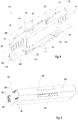
- the first body 13 can be a profiled bar having an L-shaped cross-section defined by a long side 20 and a short side 21.
- this conformation of the first body 13 allows the position of the first body to be stabilized with respect to that of the at least one second body 14 along both directions perpendicular with respect to the linear direction X.
- the magnets 18 can be placed on the long side 20 of the profiled bar.
- the magnets 18 can be placed in the central area of the long side 20 that extends along the linear direction X.
- the short side 21 is not affected by the action of the means 19 on the magnets 18 and can advantageously be used to connect a thread-carrying tool, also referred to below as a support member 24.
- the guiding device 10 may comprise one or more insulating elements 22 associated with the magnets 18 and/or the means 19 for generating a variable magnetic field, so as to thermally isolate the first body 13 and the at least one second body 14 from the heat generated by the magnets 18 and/or by the means 19.
- the insulating elements 22 may comprise epoxy glass or other heat-insulating materials.
- the insulating element 22 can be placed between the magnets 18 and the first body 13 along the linear direction X and/or also between the means 19 and the second body 14.
- the guiding device 10 may comprise a cooling unit 23 configured to cool at least the first body 13 by means of a cooling fluid.
- the guiding device 10 may comprise a cooling unit 23 configured to cool at least the second body 14 by means of a cooling fluid.
- the cooling unit 23 may comprise cooling ducts integrated or coupled to the second body 14 and fluidly connected to a cooling source which supplies a cooling fluid.
- the cooling unit 23 may comprise one or more fans configured to circulate air along the linear direction X.
- the fans are configured to generate an air flow that circulates along the linear direction X and exits through the opening from which the support member 24 protrudes.
- the means 19 for generating a variable magnetic field can be coupled to a cooling unit 23 configured to cool the means 19 and/or the at least one second body 14 to bring and maintain the temperature within the operating values.
- the guiding device 10 may comprise at least two second bodies 14 between which the first body 13 is interposed, wherein each of the at least two second bodies 14 is provided with respective means for generating a respective variable magnetic field.
- This aspect is particularly advantageous in that the combined action of the two second bodies 14 between which the first body 13 is interposed provides greater stability and uniformity of thrust to the first body 13.
- the two second bodies 14 facing towards the first body 13 allow the balance of the attraction force and, furthermore, significant containment of the load on the aerostatic spacers 27, since the attraction force between the second bodies 14 and the first body 13 produces a pre-load useful for optimizing the action of aerostatic spacers 27.
- the guiding device 10 may comprise a single management and control unit 31 configured to modulate both variable magnetic fields generated by the respective means 19 of the at least two second bodies 14, by means of a control signal sent by the management and control unit 31 to the means 19.
- the guiding device 10 may comprise at least two management and control units 31, each configured to modulate the respective variable magnetic field generated by the respective means 19 of the at least two second bodies 14, by means of a respective control signal sent by the management and control unit 31 to the respective means 19.
- the magnets 18 are placed on both sides of the long side 20 of the first body 13 along the linear direction X, while the means 19 are placed on the two second bodies 14 facing towards a respective face of the long side 20 of the first body 13.
- the combined action of the means 19 for generating a magnetic field on the magnets 18 allows the first body 13 to be maintained in the correct position, significantly reducing the load supported by the spacer assembly 16.
- This solution allows the movement of the first body 13 to be sped up even more and, furthermore, allows reduction of the load on the second bodies 14 considered individually with the same thrust obtained with a single second body 14 provided with means 19 for generating a variable magnetic field.
- the guiding device 10 of an apparatus for producing sanitary articles according to the present invention can reach speeds of movement of the first body 13 of up to 12 m/s with accelerations at full speed even higher than 230 m/s 2 and with strokes even greater than 30 cm.
- the present invention has the considerable advantage that it allows generation of high energy which can be used to supply the guiding device 10 itself and/or other devices.
- the combined and synergic action of the spacer assembly 16 and of the magnetic movement assembly 15 allow accelerations and decelerations of up to 250-350 m/s 2 to be reached.
- the variations in reciprocal speed of the magnets 18 with respect to the means 19 and, in particular, the deceleration step allows generation of an electric current in the means 19 which can be conveyed towards the network and/or other components according to the specific requirements.
- the electrical energy generated during the deceleration step of the first body 13 on which the magnets 18 are arranged can be used to supply the spacer assembly 16 and/or the magnetic power supply assembly 15. This makes it possible to make the guiding device 10 at least partly self-powered.
- the ratio between the respective lengths along the linear direction X of the first body 13 and of the second body 14 can be greater than or equal to 1.
- the ratio between the respective lengths along the linear direction X of the first body 13 and of the second body 14 can be from 1 to 3.
- the ratio between the respective lengths along the linear direction X of the first body 13 and of the second body 14 can be from 1.5 to 2.5.
- the area of action of the means 19 on the at least one second body 14 faces, for its greater part, or for its totality, towards the area of the first body 13 where the magnets 18 are arranged.
- the guiding device 10 may comprise a support member 24 connected to the first body 13 and configured to connect a tool to carry the thread 11, in which the support member extends, at least in part, out of the at least one second body 14.
- This aspect makes it possible to position and guide the thread 11 in a region which is far from both the magnetic movement unit 15 and the spacer assembly 16. This is advantageous in that the thread 11, the tool and the support member 24 are not affected by the magnetic field or by the action of the spacer assembly 16.
- the support member 24 and/or the tool can simultaneously carry and guide a plurality of threads 11.
- the support member 24 can be fixed to the short side 21 of the first body 13 by means of suitable fastening elements such as, for example, pegs, welding joints, or the like. According to possible embodiments, the support member 24 can be made in a single piece with the first body 13.
- the guiding device 10 may comprise a casing 25 configured to contain the first body 13, the at least one second body 14, the spacer assembly 16 and the magnetic movement assembly 15.
- the casing 25 is provided with a slot 26 along which at least part of the support member 24 comes out and slides.
- the casing 25 may comprise a plurality of shells which can be connected to each other in a removable manner.
- the connectors 30 assigned to the electrical connection or to the fluid connection can be it air, or with any other gas, as well as with a cooling fluid, can be arranged on the side faces of the casing 25 placed transversely with respect to the linear direction X.
- the spacer assembly may comprise a plurality of aerostatic spacer elements 27, 127 each configured to generate a respective air cushion in order to locally distance the first body 13 from the at least one second body 14.
- This aspect allows distancing the first body 13 away from the at least one second body 14 in a desired manner and when required, also diversified, making the guiding device 10 flexible for use in multiple conditions and settings.
- the guiding device 10 may comprise a first body 13 and a single second body 14.
- the first body 13 can be a profiled bar, or a profiled bar having an inverted-U-shaped cross-section.
- the magnetic attraction force between the means 19 and the magnets 18 allows the first body 13 to be retained in the correct position.
- the magnetic attraction force between the means 19 and the magnets 18 allows the first body 13 to be retained in the correct position, avoiding that, above all in the step of actuating the aerostatic spacer elements 27, the first body 13 is excessively distanced from the second body 14.
- the spacer assembly 16 may comprise at least one aerostatic spacer element 27 which acts to space the first body 13 apart from the respective second body 14 along a first direction perpendicular with respect to the linear direction X and at least one other aerostatic spacer element 127 which acts to space the first body 13 away from the respective second body 14 along a second direction perpendicular to the linear direction X.
- the first and the second perpendicular direction are perpendicular to each other.
- the spacer assembly 16 may comprise at least one pair of aerostatic spacer elements 27 configured to space apart the long side 20 from the two second bodies 14 along a first direction perpendicular to the surface 32 of the first body 13 affected by the magnetic movement assembly 15, or the surface 32 facing the means 19 for generating the variable magnetic field, or rather the surface 32 on which the magnets are arranged 18.
- the spacer assembly 16 may comprise a pair of aerostatic spacer elements 127 configured to space apart the short side 21 from the second bodies 14 along a second direction perpendicular to the first perpendicular direction.
- This aspect allows the first body 13 to be stabilized and kept at a distance from the second bodies 14 along both directions perpendicular to the linear direction X.
- the aerostatic spacer elements 27 can be placed on the at least one second body 14 at the sides of the magnetic movement assembly 15.
- the aerostatic spacer elements 27 can face towards the side portions 28 of the first body 13 between which the magnets 18 are arranged.
- This aspect allows both stabilization of the positioning of the first body 13 with respect to the at least one second body 14, and separation of the area of action of the magnetic movement assembly 15 with respect to the areas of action of the aerostatic spacer elements 27.
- the presence of the aerostatic spacer elements 27 on the at least one second body 14 at the sides of the magnetic movement assembly 15 allows positioning of the first body 13 on a stable and defined plane of arrangement, while ensuring continuity of operation without undesired interference between the spacer assembly 16 and the magnetic drive assembly 15.
- the side portions 28 can be provided with tracks comprising anti-friction material configured to reduce the friction between the first body 13 on the at least one second body 14 if there is contact between the first body and the second body.
- the track may include a material called Turcite®, or other similar materials.
- the spacer assembly 16 may comprise at least one magnetic spacer element configured to locally distance the first body 13 from the at least one second body 14 by means of another magnetic force.
- the magnetic spacer elements may comprise magnets and/or means for generating a magnetic field and are located on the sides of the magnetic movement assembly 15 so as not to hinder the action of its movement.
- the magnetic spacer elements can be substantially configured in a manner analogous to the magnetic movement assembly 15, but with the object of distancing the first body 13 from the at least one second body 14 instead of moving the first body 13 with respect to the at least one second body 14.
- the magnetic spacer elements can be located either on the long side 20, or on the short side 21.
- This aspect allows reduction of the energy consumption to generate the air cushion, since part of the energy necessary to distance the first body 13 from the at least one second body 14 is supplied by one or more magnetic spacer elements, also passively, or rather, by permanent magnets.
- the present invention also relates to a method using a guiding device 10 of an apparatus for producing sanitary articles as described in any one of the embodiments described for applying a thread 11 onto a substrate 12 intended for producing sanitary articles.
- the method envisages: associating the thread 11 with a first body 13 movable along a linear direction X; spacing the first body 13 apart from the at least one second body 14 that is fixed with respect to the first body 13, by means of an air cushion; and moving the first body 13 along the linear direction X by a magnetic force so as to guide the thread 11 in order to apply it onto the substrate 12.
- the movement of the first body 13 can be obtained by means of a magnetic movement assembly 15 comprising a plurality of magnets 18, placed on the first body 13, and means 19 for generating a variable magnetic field, placed on the at least one second body 14.
- the method envisages generating electrical energy by electromagnetic induction, while the first body 13 decelerates, and feeding an apparatus with the generated electric energy.
- This aspect makes it possible to generate electrical energy that can be used to supply parts of the guiding device 10 such as, for example, the spacer assembly 16, and/or other devices and/or apparatuses.
- the method may envisage setting a desired timetable defining the position of the first body 13 along the linear direction X in relation to time, and for moving the first body 13 according to the set timetable.
- the method may envisage modulating the movement of the first body 13 in relation to the elasticity of the thread 11 and to the instantaneous position of the first body 13 along the linear direction X.
Landscapes
- Health & Medical Sciences (AREA)
- Engineering & Computer Science (AREA)
- Animal Behavior & Ethology (AREA)
- General Health & Medical Sciences (AREA)
- Biomedical Technology (AREA)
- Heart & Thoracic Surgery (AREA)
- Vascular Medicine (AREA)
- Life Sciences & Earth Sciences (AREA)
- Manufacturing & Machinery (AREA)
- Epidemiology (AREA)
- Public Health (AREA)
- Veterinary Medicine (AREA)
- Absorbent Articles And Supports Therefor (AREA)
- Electrical Discharge Machining, Electrochemical Machining, And Combined Machining (AREA)
- Media Introduction/Drainage Providing Device (AREA)
- Coating With Molten Metal (AREA)
- Woven Fabrics (AREA)
Applications Claiming Priority (1)
| Application Number | Priority Date | Filing Date | Title |
|---|---|---|---|
| IT201800006019A IT201800006019A1 (it) | 2018-06-08 | 2018-06-08 | Dispositivo di guida per l'applicazione di un filo e procedimento |
Publications (1)
| Publication Number | Publication Date |
|---|---|
| EP3578149A1 true EP3578149A1 (fr) | 2019-12-11 |
Family
ID=63684236
Family Applications (1)
| Application Number | Title | Priority Date | Filing Date |
|---|---|---|---|
| EP19177850.5A Withdrawn EP3578149A1 (fr) | 2018-06-08 | 2019-06-03 | Dispositif de guidage d'un appareil de production d'articles sanitaires pour appliquer un fil et procédé associé |
Country Status (5)
| Country | Link |
|---|---|
| US (1) | US20190374393A1 (fr) |
| EP (1) | EP3578149A1 (fr) |
| JP (1) | JP3222683U (fr) |
| CN (1) | CN210932233U (fr) |
| IT (1) | IT201800006019A1 (fr) |
Citations (6)
| Publication number | Priority date | Publication date | Assignee | Title |
|---|---|---|---|---|
| US4801345A (en) * | 1980-09-15 | 1989-01-31 | Boussac Saint Freres B.S.F. | Process for manufacturing disposable diapers and diaper briefs, and disposable diapers and diaper briefs obtained by application of this process |
| US5525175A (en) * | 1994-05-27 | 1996-06-11 | Kimberly-Clark Corporation | Apparatus and method for applying a curved elastic to a moving web |
| WO2000024663A1 (fr) | 1998-10-28 | 2000-05-04 | Maschinenfabrik Rieter Ag | Va-et-vient de fil |
| EP1148016A2 (fr) | 2000-04-20 | 2001-10-24 | Berger Lahr GmbH & Co. KG | Dispositif pour enrouler un fil sur une bobine |
| WO2003002443A1 (fr) * | 2001-06-27 | 2003-01-09 | Rieter Icbt | Mecanisme de va et vient pour le bobinage de fils |
| DE102013225653A1 (de) | 2013-12-11 | 2015-06-11 | Schaeffler Technologies AG & Co. KG | Fadentraversiervorrichtung und Verfahren zum Betrieb einer Fadentraversiervorrichtung |
-
2018
- 2018-06-08 IT IT201800006019A patent/IT201800006019A1/it unknown
-
2019
- 2019-06-03 EP EP19177850.5A patent/EP3578149A1/fr not_active Withdrawn
- 2019-06-07 US US16/434,221 patent/US20190374393A1/en not_active Abandoned
- 2019-06-07 JP JP2019002058U patent/JP3222683U/ja active Active
- 2019-06-10 CN CN201920861039.0U patent/CN210932233U/zh active Active
Patent Citations (6)
| Publication number | Priority date | Publication date | Assignee | Title |
|---|---|---|---|---|
| US4801345A (en) * | 1980-09-15 | 1989-01-31 | Boussac Saint Freres B.S.F. | Process for manufacturing disposable diapers and diaper briefs, and disposable diapers and diaper briefs obtained by application of this process |
| US5525175A (en) * | 1994-05-27 | 1996-06-11 | Kimberly-Clark Corporation | Apparatus and method for applying a curved elastic to a moving web |
| WO2000024663A1 (fr) | 1998-10-28 | 2000-05-04 | Maschinenfabrik Rieter Ag | Va-et-vient de fil |
| EP1148016A2 (fr) | 2000-04-20 | 2001-10-24 | Berger Lahr GmbH & Co. KG | Dispositif pour enrouler un fil sur une bobine |
| WO2003002443A1 (fr) * | 2001-06-27 | 2003-01-09 | Rieter Icbt | Mecanisme de va et vient pour le bobinage de fils |
| DE102013225653A1 (de) | 2013-12-11 | 2015-06-11 | Schaeffler Technologies AG & Co. KG | Fadentraversiervorrichtung und Verfahren zum Betrieb einer Fadentraversiervorrichtung |
Also Published As
| Publication number | Publication date |
|---|---|
| IT201800006019A1 (it) | 2019-12-08 |
| CN210932233U (zh) | 2020-07-07 |
| US20190374393A1 (en) | 2019-12-12 |
| JP3222683U (ja) | 2019-08-15 |
Similar Documents
| Publication | Publication Date | Title |
|---|---|---|
| US8100253B2 (en) | Methods and apparatuses for transferring discrete articles between carriers | |
| AU778739B2 (en) | Transverse flux induction heating device with magnetic circuit of variable width | |
| EP1260203B1 (fr) | Procédé et dispositif de production de vêtements | |
| US10106339B2 (en) | XY table for a linear transport system | |
| US20200223646A1 (en) | Method for operating a transport apparatus in the form of a long stator linear motor | |
| DE102014003882B4 (de) | Transportvorrichtung zum Bewegen und/oder Positionieren von Objekten | |
| CN106348022B (zh) | 结构合理、可靠的自驱式磁悬浮曲直复合循环型传送单元 | |
| US6024005A (en) | Formation stabilizing guide for braider | |
| CN112606432B (zh) | 一种用于复合材料预浸带成型制造的铺带装置 | |
| JP7337160B2 (ja) | 平坦材料のプレス処理のための装置 | |
| CN109217622B (zh) | 长定子直线电机形式的运输设备 | |
| CN102505394A (zh) | 一种用于拉幅定型机中的低能耗无电机驱动式传送装置 | |
| US20190374393A1 (en) | Guiding device of an apparatus for producing sanitary articles for applying a thread, and relative method | |
| CN110300821B (zh) | 用于制造编织物的编织机和方法 | |
| CN101091940A (zh) | 为经过的织物施加液体的装置 | |
| US11234869B2 (en) | Guiding device of an apparatus for producing sanitary articles for applying a thread, and relative method | |
| EP3770311A1 (fr) | Métier à tisser circulaire à trajectoire périphérique | |
| US7332836B2 (en) | Guide bar drive in a knitting machine | |
| CN115397693B (zh) | 非接触式电力传输及其动力装置 | |
| JP2023045058A (ja) | キャリア及び編組機 | |
| CN220844526U (zh) | 一种电磁滑块装置 | |
| CN112896961A (zh) | 一种传输机构 | |
| CN109929973A (zh) | 淬火电源移动滑台 | |
| CN103485108B (zh) | 导向系统结构合理的磁悬浮拉幅定型传送系统 | |
| WO2019092655A1 (fr) | Machine à tisser à projectiles présentant une circulation continue de projectiles, à rendement amélioré |
Legal Events
| Date | Code | Title | Description |
|---|---|---|---|
| PUAI | Public reference made under article 153(3) epc to a published international application that has entered the european phase |
Free format text: ORIGINAL CODE: 0009012 |
|
| AK | Designated contracting states |
Kind code of ref document: A1 Designated state(s): AL AT BE BG CH CY CZ DE DK EE ES FI FR GB GR HR HU IE IS IT LI LT LU LV MC MK MT NL NO PL PT RO RS SE SI SK SM TR |
|
| AX | Request for extension of the european patent |
Extension state: BA ME |
|
| 17P | Request for examination filed |
Effective date: 20200115 |
|
| RBV | Designated contracting states (corrected) |
Designated state(s): AL AT BE BG CH CY CZ DE DK EE ES FI FR GB GR HR HU IE IS IT LI LT LU LV MC MK MT NL NO PL PT RO RS SE SI SK SM TR |
|
| 17Q | First examination report despatched |
Effective date: 20200415 |
|
| RAP1 | Party data changed (applicant data changed or rights of an application transferred) |
Owner name: FAMECCANICA.DATA S.P.A. |
|
| STAA | Information on the status of an ep patent application or granted ep patent |
Free format text: STATUS: THE APPLICATION IS DEEMED TO BE WITHDRAWN |
|
| 18D | Application deemed to be withdrawn |
Effective date: 20200826 |