EP3578253A1 - Ausgabevorrichtung eines mehrphasigen gemischs in einen behälter, der ein verflüssigtes milieu enthält - Google Patents
Ausgabevorrichtung eines mehrphasigen gemischs in einen behälter, der ein verflüssigtes milieu enthält Download PDFInfo
- Publication number
- EP3578253A1 EP3578253A1 EP19175753.3A EP19175753A EP3578253A1 EP 3578253 A1 EP3578253 A1 EP 3578253A1 EP 19175753 A EP19175753 A EP 19175753A EP 3578253 A1 EP3578253 A1 EP 3578253A1
- Authority
- EP
- European Patent Office
- Prior art keywords
- windows
- branch
- reaction chamber
- pipe
- dispensing device
- Prior art date
- Legal status (The legal status is an assumption and is not a legal conclusion. Google has not performed a legal analysis and makes no representation as to the accuracy of the status listed.)
- Withdrawn
Links
Images



Classifications
-
- B—PERFORMING OPERATIONS; TRANSPORTING
- B01—PHYSICAL OR CHEMICAL PROCESSES OR APPARATUS IN GENERAL
- B01J—CHEMICAL OR PHYSICAL PROCESSES, e.g. CATALYSIS OR COLLOID CHEMISTRY; THEIR RELEVANT APPARATUS
- B01J4/00—Feed or outlet devices; Feed or outlet control devices
- B01J4/001—Feed or outlet devices as such, e.g. feeding tubes
- B01J4/002—Nozzle-type elements
-
- B—PERFORMING OPERATIONS; TRANSPORTING
- B01—PHYSICAL OR CHEMICAL PROCESSES OR APPARATUS IN GENERAL
- B01J—CHEMICAL OR PHYSICAL PROCESSES, e.g. CATALYSIS OR COLLOID CHEMISTRY; THEIR RELEVANT APPARATUS
- B01J8/00—Chemical or physical processes in general, conducted in the presence of fluids and solid particles; Apparatus for such processes
- B01J8/18—Chemical or physical processes in general, conducted in the presence of fluids and solid particles; Apparatus for such processes with fluidised particles
- B01J8/1872—Details of the fluidised bed reactor
-
- B—PERFORMING OPERATIONS; TRANSPORTING
- B01—PHYSICAL OR CHEMICAL PROCESSES OR APPARATUS IN GENERAL
- B01J—CHEMICAL OR PHYSICAL PROCESSES, e.g. CATALYSIS OR COLLOID CHEMISTRY; THEIR RELEVANT APPARATUS
- B01J8/00—Chemical or physical processes in general, conducted in the presence of fluids and solid particles; Apparatus for such processes
- B01J8/0015—Feeding of the particles in the reactor; Evacuation of the particles out of the reactor
- B01J8/004—Feeding of the particles in the reactor; Evacuation of the particles out of the reactor by means of a nozzle
-
- B—PERFORMING OPERATIONS; TRANSPORTING
- B01—PHYSICAL OR CHEMICAL PROCESSES OR APPARATUS IN GENERAL
- B01J—CHEMICAL OR PHYSICAL PROCESSES, e.g. CATALYSIS OR COLLOID CHEMISTRY; THEIR RELEVANT APPARATUS
- B01J8/00—Chemical or physical processes in general, conducted in the presence of fluids and solid particles; Apparatus for such processes
- B01J8/08—Chemical or physical processes in general, conducted in the presence of fluids and solid particles; Apparatus for such processes with moving particles
- B01J8/085—Feeding reactive fluids
-
- B—PERFORMING OPERATIONS; TRANSPORTING
- B01—PHYSICAL OR CHEMICAL PROCESSES OR APPARATUS IN GENERAL
- B01J—CHEMICAL OR PHYSICAL PROCESSES, e.g. CATALYSIS OR COLLOID CHEMISTRY; THEIR RELEVANT APPARATUS
- B01J8/00—Chemical or physical processes in general, conducted in the presence of fluids and solid particles; Apparatus for such processes
- B01J8/08—Chemical or physical processes in general, conducted in the presence of fluids and solid particles; Apparatus for such processes with moving particles
- B01J8/12—Chemical or physical processes in general, conducted in the presence of fluids and solid particles; Apparatus for such processes with moving particles moved by gravity in a downward flow
- B01J8/125—Chemical or physical processes in general, conducted in the presence of fluids and solid particles; Apparatus for such processes with moving particles moved by gravity in a downward flow with multiple sections one above the other separated by distribution aids, e.g. reaction and regeneration sections
-
- B—PERFORMING OPERATIONS; TRANSPORTING
- B01—PHYSICAL OR CHEMICAL PROCESSES OR APPARATUS IN GENERAL
- B01J—CHEMICAL OR PHYSICAL PROCESSES, e.g. CATALYSIS OR COLLOID CHEMISTRY; THEIR RELEVANT APPARATUS
- B01J8/00—Chemical or physical processes in general, conducted in the presence of fluids and solid particles; Apparatus for such processes
- B01J8/18—Chemical or physical processes in general, conducted in the presence of fluids and solid particles; Apparatus for such processes with fluidised particles
- B01J8/1818—Feeding of the fluidising gas
-
- B—PERFORMING OPERATIONS; TRANSPORTING
- B01—PHYSICAL OR CHEMICAL PROCESSES OR APPARATUS IN GENERAL
- B01J—CHEMICAL OR PHYSICAL PROCESSES, e.g. CATALYSIS OR COLLOID CHEMISTRY; THEIR RELEVANT APPARATUS
- B01J8/00—Chemical or physical processes in general, conducted in the presence of fluids and solid particles; Apparatus for such processes
- B01J8/18—Chemical or physical processes in general, conducted in the presence of fluids and solid particles; Apparatus for such processes with fluidised particles
- B01J8/1818—Feeding of the fluidising gas
- B01J8/1827—Feeding of the fluidising gas the fluidising gas being a reactant
-
- B—PERFORMING OPERATIONS; TRANSPORTING
- B01—PHYSICAL OR CHEMICAL PROCESSES OR APPARATUS IN GENERAL
- B01J—CHEMICAL OR PHYSICAL PROCESSES, e.g. CATALYSIS OR COLLOID CHEMISTRY; THEIR RELEVANT APPARATUS
- B01J8/00—Chemical or physical processes in general, conducted in the presence of fluids and solid particles; Apparatus for such processes
- B01J8/18—Chemical or physical processes in general, conducted in the presence of fluids and solid particles; Apparatus for such processes with fluidised particles
- B01J8/20—Chemical or physical processes in general, conducted in the presence of fluids and solid particles; Apparatus for such processes with fluidised particles with liquid as a fluidising medium
- B01J8/22—Chemical or physical processes in general, conducted in the presence of fluids and solid particles; Apparatus for such processes with fluidised particles with liquid as a fluidising medium gas being introduced into the liquid
-
- B—PERFORMING OPERATIONS; TRANSPORTING
- B01—PHYSICAL OR CHEMICAL PROCESSES OR APPARATUS IN GENERAL
- B01J—CHEMICAL OR PHYSICAL PROCESSES, e.g. CATALYSIS OR COLLOID CHEMISTRY; THEIR RELEVANT APPARATUS
- B01J8/00—Chemical or physical processes in general, conducted in the presence of fluids and solid particles; Apparatus for such processes
- B01J8/18—Chemical or physical processes in general, conducted in the presence of fluids and solid particles; Apparatus for such processes with fluidised particles
- B01J8/24—Chemical or physical processes in general, conducted in the presence of fluids and solid particles; Apparatus for such processes with fluidised particles according to "fluidised-bed" technique
-
- B—PERFORMING OPERATIONS; TRANSPORTING
- B01—PHYSICAL OR CHEMICAL PROCESSES OR APPARATUS IN GENERAL
- B01J—CHEMICAL OR PHYSICAL PROCESSES, e.g. CATALYSIS OR COLLOID CHEMISTRY; THEIR RELEVANT APPARATUS
- B01J8/00—Chemical or physical processes in general, conducted in the presence of fluids and solid particles; Apparatus for such processes
- B01J8/18—Chemical or physical processes in general, conducted in the presence of fluids and solid particles; Apparatus for such processes with fluidised particles
- B01J8/24—Chemical or physical processes in general, conducted in the presence of fluids and solid particles; Apparatus for such processes with fluidised particles according to "fluidised-bed" technique
- B01J8/26—Chemical or physical processes in general, conducted in the presence of fluids and solid particles; Apparatus for such processes with fluidised particles according to "fluidised-bed" technique with two or more fluidised beds, e.g. reactor and regeneration installations
-
- B—PERFORMING OPERATIONS; TRANSPORTING
- B01—PHYSICAL OR CHEMICAL PROCESSES OR APPARATUS IN GENERAL
- B01J—CHEMICAL OR PHYSICAL PROCESSES, e.g. CATALYSIS OR COLLOID CHEMISTRY; THEIR RELEVANT APPARATUS
- B01J8/00—Chemical or physical processes in general, conducted in the presence of fluids and solid particles; Apparatus for such processes
- B01J8/18—Chemical or physical processes in general, conducted in the presence of fluids and solid particles; Apparatus for such processes with fluidised particles
- B01J8/24—Chemical or physical processes in general, conducted in the presence of fluids and solid particles; Apparatus for such processes with fluidised particles according to "fluidised-bed" technique
- B01J8/44—Fluidisation grids
-
- C—CHEMISTRY; METALLURGY
- C10—PETROLEUM, GAS OR COKE INDUSTRIES; TECHNICAL GASES CONTAINING CARBON MONOXIDE; FUELS; LUBRICANTS; PEAT
- C10G—CRACKING HYDROCARBON OILS; PRODUCTION OF LIQUID HYDROCARBON MIXTURES, e.g. BY DESTRUCTIVE HYDROGENATION, OLIGOMERISATION, POLYMERISATION; RECOVERY OF HYDROCARBON OILS FROM OIL-SHALE, OIL-SAND, OR GASES; REFINING MIXTURES MAINLY CONSISTING OF HYDROCARBONS; REFORMING OF NAPHTHA; MINERAL WAXES
- C10G47/00—Cracking of hydrocarbon oils, in the presence of hydrogen or hydrogen- generating compounds, to obtain lower boiling fractions
- C10G47/24—Cracking of hydrocarbon oils, in the presence of hydrogen or hydrogen- generating compounds, to obtain lower boiling fractions with moving solid particles
- C10G47/30—Cracking of hydrocarbon oils, in the presence of hydrogen or hydrogen- generating compounds, to obtain lower boiling fractions with moving solid particles according to the "fluidised-bed" technique
-
- C—CHEMISTRY; METALLURGY
- C10—PETROLEUM, GAS OR COKE INDUSTRIES; TECHNICAL GASES CONTAINING CARBON MONOXIDE; FUELS; LUBRICANTS; PEAT
- C10G—CRACKING HYDROCARBON OILS; PRODUCTION OF LIQUID HYDROCARBON MIXTURES, e.g. BY DESTRUCTIVE HYDROGENATION, OLIGOMERISATION, POLYMERISATION; RECOVERY OF HYDROCARBON OILS FROM OIL-SHALE, OIL-SAND, OR GASES; REFINING MIXTURES MAINLY CONSISTING OF HYDROCARBONS; REFORMING OF NAPHTHA; MINERAL WAXES
- C10G49/00—Treatment of hydrocarbon oils, in the presence of hydrogen or hydrogen-generating compounds, not provided for in a single one of groups C10G45/02, C10G45/32, C10G45/44, C10G45/58 or C10G47/00
- C10G49/10—Treatment of hydrocarbon oils, in the presence of hydrogen or hydrogen-generating compounds, not provided for in a single one of groups C10G45/02, C10G45/32, C10G45/44, C10G45/58 or C10G47/00 with moving solid particles
- C10G49/16—Treatment of hydrocarbon oils, in the presence of hydrogen or hydrogen-generating compounds, not provided for in a single one of groups C10G45/02, C10G45/32, C10G45/44, C10G45/58 or C10G47/00 with moving solid particles according to the "fluidised-bed" technique
-
- B—PERFORMING OPERATIONS; TRANSPORTING
- B01—PHYSICAL OR CHEMICAL PROCESSES OR APPARATUS IN GENERAL
- B01J—CHEMICAL OR PHYSICAL PROCESSES, e.g. CATALYSIS OR COLLOID CHEMISTRY; THEIR RELEVANT APPARATUS
- B01J2208/00—Processes carried out in the presence of solid particles; Reactors therefor
- B01J2208/00796—Details of the reactor or of the particulate material
- B01J2208/00893—Feeding means for the reactants
-
- B—PERFORMING OPERATIONS; TRANSPORTING
- B01—PHYSICAL OR CHEMICAL PROCESSES OR APPARATUS IN GENERAL
- B01J—CHEMICAL OR PHYSICAL PROCESSES, e.g. CATALYSIS OR COLLOID CHEMISTRY; THEIR RELEVANT APPARATUS
- B01J2208/00—Processes carried out in the presence of solid particles; Reactors therefor
- B01J2208/00796—Details of the reactor or of the particulate material
- B01J2208/00893—Feeding means for the reactants
- B01J2208/00911—Sparger-type feeding elements
-
- B—PERFORMING OPERATIONS; TRANSPORTING
- B01—PHYSICAL OR CHEMICAL PROCESSES OR APPARATUS IN GENERAL
- B01J—CHEMICAL OR PHYSICAL PROCESSES, e.g. CATALYSIS OR COLLOID CHEMISTRY; THEIR RELEVANT APPARATUS
- B01J2208/00—Processes carried out in the presence of solid particles; Reactors therefor
- B01J2208/00796—Details of the reactor or of the particulate material
- B01J2208/00938—Flow distribution elements
Definitions
- the present description is part of the improvement of the design of the distributors for the distribution of a fluid phase, generally light, in a reaction chamber containing a fluid phase, generally dense.
- the light fluid phase is a gas, gas-solid, gas-liquid, liquid or liquid-solid phase
- the dense fluid phase is the fluidized bed itself, that is, the suspension of solid particles dispersed in gas and / or liquid.
- the reaction chamber is a fluidized bed, which contains a solid phase (catalytic or not), maintained in suspension in the pseudo-fluid state by the passage of a gaseous fluid, liquid, a mixture of gas and liquid fluids, or a pseudo-fluid consisting of gas or liquid containing particles in suspension
- the essential role of the distribution is to maintain the fluidization of the solid in the reaction chamber while ensuring a good mixing of the all phases thus making it possible to have good homogeneity of the products within the fluidized bed.
- the patent US5571482 discloses a gas distributor disposed at the top of a fluidized bed reactor with gas-solid upward co-current ("riser” in the English terminology) in a regenerator, comprising a mushroom-shaped lid provided with orifices and including notches on the rim of the lid.
- the patent FR3006607 discloses a light phase distributor in a dense phase comprising a deflection means disposed on the outer surface of the lid.
- the patent US5156817 discloses a dispenser having a plurality of triangular section dispensing arms and whose lower edges are serrated.
- the patent US6221318 discloses a dispenser having a plurality of dispensing arms having different endings.
- a first object of the present invention is to provide dispensing devices for a better distribution of a first fluid phase (ie, light phase) in a reaction chamber containing a second fluid phase ( ie, heavy phase ) having a density greater than the light fluid phase to be dispensed.
- This difference in density may be due to either a volume fraction of solid or a volume fraction of liquid of the injected phase lower than that of the phase contained in the capacity where the phases must be mixed.
- a second object of the present invention is to provide dispensing devices for better mixing between phases and better reaction performance.
- the first windows are adapted so that a first portion of the light fluid phase distributed on the periphery of the reaction chamber exits through the first windows with a first speed
- the second windows are adapted from so that a second portion of the light fluid phase distributed on the central part of the reaction chamber exits through the second windows with a second speed
- the passage sections of the first and second windows are formed in such a way that the first speed and second gear is included between 0.1 ⁇ V and 30 ⁇ V, V designating the speed of said light fluid phase in the pipe and being between 1 m / s and 100 m / s.
- the intermediate windows are adapted so that a central portion of the first portion of the light fluid phase is distributed at an intermediate position of the reaction chamber and exits through the intermediate windows with a third gear
- the branch end windows are adapted so that side portions of the first portion of the light fluid phase are distributed to an outer position of the reaction chamber and exit through the branch end windows with a fourth speed the passage sections of the intermediate windows and the branch end windows are formed in such a way that the third speed and the fourth speed are between 0.5 ⁇ V 2 and 3 ⁇ V 2, V 2 being the second speed.
- the branches are of length a between 0.1 ⁇ D and 0.5 ⁇ D, D being the diameter of the reaction chamber.
- the first and second windows are alternately arranged, and / or are in even numbers, and / or are of the same number, in particular to ensure a symmetry of the flow.
- the width of the section of passage formed by the branch increases linearly, curved or crenellated from the pipe.
- the width of the branches is increased from the pipe in the branch axis by two angles ⁇ over a distance f, the angle ⁇ being between 0 ° and 60 °, the distance f being between 0 ⁇ a and 1 ⁇ a, where a is the length of the branches.
- the height of the passage section formed by the branch decreases linearly, curved or crenellated from the pipe.
- the height of the branches is reduced from the pipe in the branch axis with an angle ⁇ over a distance f, the angle ⁇ being between 0 ° and 85 °, the distance f being between 0 ⁇ a and 1 ⁇ a, where a is the length of the branches.
- the distance b in the branch axis between the pipe and a central wall dividing the branch into said central passage and said lateral passages is between 0.1 ⁇ a and 0.9 ⁇ a, a being the length of the branches.
- the intermediate window is placed at the edge of the central wall.
- a reactor comprising a dispensing device according to the first aspect.
- the reactor comprising a single dispensing device. According to one or more embodiments, the reactor comprising a plurality of dispensing devices.
- the abovementioned objects, as well as other advantages, are obtained by a catalytic cracking process with two regeneration zones using the dispensing device according to the first aspect, to effect the passage of a catalyst of a first regeneration zone to a second turbulent fluidized bed regeneration zone.
- a biomass treatment method using the dispensing device according to the first aspect to effect the introduction of a gas phase, or a solid gas suspension in a fluidized medium, for example in a catalytic pyrolysis reactor, for example carrying out the introduction of hydrogen and / or solid particles into a fluidized medium containing solid particles.
- the aforementioned objects, as well as other advantages, are obtained by a process for hydrotreating heavy petroleum cuts using the dispensing device according to the first aspect, for effecting the introduction of hydrogen into a fluidized medium. containing solid particles (eg catalyst) and optionally a heavy hydrocarbon phase to be treated.
- solid particles eg catalyst
- groups of chemical elements are given according to the CAS classification ( CRC Handbook of Chemistry and Physics, Editor CRC Press, Editor-in-Chief DR Lide, 81st Edition, 2000-2001 ).
- group VIII according to the CAS classification corresponds to the metals of columns 8, 9 and 10 according to the new IUPAC classification.
- the dispensing device can be defined as a device for the distribution of a light fluid phase within a heavy phase (ie , mixture of higher density fluids) in a reaction chamber containing said phase heavy, for example in the fluidized state.
- a heavy phase ie , mixture of higher density fluids
- the light fluid phase can be a gas, gas-solid, gas-liquid, liquid or liquid-solid phase. According to one or more embodiments, the light fluid phase is a gas-solid or liquid-solid phase. According to one or more embodiments, the light fluid phase is a gas-solid phase.
- the heavy phase can be a gas-solid emulsion or even a three-phase gas-solid-liquid medium, as for example in the processes of hydrotreating of petroleum fractions.
- the density ratio between the heavy phase and the light phase is between 1.1 and 5000.
- the dispensing device is particularly suitable for the distribution of a light fluid phase in a fluidized bed reactor, such as a three-phase bubbling fluidized bed reactor in which the solid catalyst is fluidized by a mixture of reactive fluids. comprising a gas and a liquid.
- the dispensing device according to the present description is particularly suitable for dispensing a gas-solid or gas-liquid phase at high temperature in a fluidized bed reactor.
- the dispensing device is particularly well suited when the light fluid phase comprises hydrogen, and when the dense fluid phase comprises a petroleum residue, in particular for implementation in a boiling bed hydroconversion stage using a three-phase fluidized reactor.
- the distribution device can be used to transfer the catalyst from a first regeneration zone to a second turbulent fluidized bed regeneration zone.
- the distribution device in the context of a biomass treatment process, can be used to introduce a gas phase, or a gas-solid suspension in the fluidized medium of the biomass treatment reactor.
- the dispensing device can be used to introduce hydrogen into a fluidized medium containing catalyst particles and a heavy hydrocarbon phase to be treated.
- the dispensing device comprises a pipe 1 of diameter R adapted to penetrate into the lower part of the reaction chamber 5 containing the heavy phase 4 in the fluidized state, and adapted to transport with a speed V the phase light fluid 2 to the reaction chamber 5.
- the dispensing device is installed in a reaction chamber 5 of diameter D between 0.5 m and 50 m, preferably between 1 m and 30 m and preferably between 2 m and 20 m.
- the dispensing device is used to distribute the light fluid phase 2 in the reaction chamber 5 below or below a gas injector 22 which may be in the form of a ring.
- the pipe 1 is cylindrical.
- the upper end of the pipe 1 is substantially centered along the axis of symmetry (i.e., vertical central axis) of the reaction chamber 5.
- the pipe 1 is vertical.
- Line 1 is preferably vertical if it carries a light multiphase fluid phase 2.
- the ratio of the diameter R of the pipe 1 to the diameter D of the reaction chamber 5 is between 0.005 and 0.9, preferably between 0.01 and 0.5, and preferably between 0.1 and 0.3.
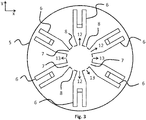
- first windows 7 and second windows 8 are drilled / opened first windows 7 and second windows 8 in the side wall of said pipe 1.
- a distributor 3 is also arranged to distribute the light fluid phase 2 at different radial positions in the reaction chamber 5.
- the distributor 3 comprises a plurality of branches 6 (also called lateral ducts) extending each of the first windows 7 from the pipe 1 in a branch axis substantially perpendicular to the axis of symmetry of the pipe 1.
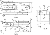
- the first windows 7 and / or the second windows 8 are of substantially rectangular shapes, the first windows 7 having a width c and a height d (ie a passage section c ⁇ d), the second windows 8 having a width m and a height l (ie a passage section mx1). It is understood that the first windows 7 and / or the second windows 8 may be openings of any shape (eg square, triangle, circle, etc.).
- the first and second windows 7 and 8 are arranged alternately. According to one or more embodiments, the first and second windows 7 and 8 are in even numbers in total and / or of the same number.
- the number of first windows 7 and / or second windows 8 is between 2 and 48, preferably between 4 and 24 and preferably between 4 and 12.
- the centers of the first and second windows 7 and 8 are separated by a distance o on the axis of symmetry z of the pipe 1 and / or offset by an angle ⁇ in the orthogonal plane xy to the axis of symmetry z of line 1.
- the angle ⁇ is between 0 ° and 180 ° and preferably between 0 ° and 90 °.
- the first windows 7 are disposed below the second windows 8 on the axis of symmetry z.
- the distance o on the axis of symmetry z between the center of the first and second windows 7 and 8 is between 0 ⁇ d and 2 ⁇ d and preferably between 0 ⁇ d and 1 ⁇ d.
- the distance o on the axis of symmetry z between the center of the first and second windows 7 and 8 is between 0 ⁇ d and 1 ⁇ d and the first and second windows 7 and 8 are arranged alternately on line 1.
- the branches 6 allow to distribute a first portion 12 of the light fluid phase 2 on the periphery of the reaction chamber 5.
- the second windows 8 open directly into the reaction chamber 5, in particular to distribute a second portion 13 the light fluid phase 2 on the central part of the reaction chamber 5.
- the first and second windows 7 and 8 are adapted so that the first portion 12 comes out of the first windows 7 with a first speed V1 to then move towards the branches 6 and the second portion 13 so directly in the reaction chamber 5 by the second windows 8 with a second speed V2.
- the passage sections of the first and second windows 7 and 8 are formed in such a way that the first speed V1 and the second speed V2 are between 0.1 ⁇ V and 30 ⁇ V, preferably between 0.3 ⁇ V and 20 ⁇ V and preferably between 0.5 ⁇ V and 10 ⁇ V, V designating the speed of said light fluid phase in line 1 and being between 1 m / s and 100 m / s and preferably between 3 m / s and 30 m / s.
- each branch 6 comprises a central wall 16 substantially perpendicular to the axis of branch x and dividing the branch 6 in three passages in an orthogonal plane xy to the axis of symmetry z of the pipe 1, a central passage opening into the reaction chamber 5 through an intermediate window 9 pierced in the upper wall of the branch 6 and of which two distinct lateral branches (hereinafter referred to as lateral passages 10), disposed on either side of the central passage of length n opening into the reaction chamber 5 through branch end windows 11.
- the length n is between 0.1 ⁇ a and 0.9 ⁇ a and preferably between 0.4 ⁇ a and 0.8 ⁇ a.
- the first portion 12 of the light fluid phase 2 is divided into three parts, a central portion 14 directed towards the central passage and two lateral portions 15 directed towards the two lateral passages 10.
- the device comprises additional lateral passages, for example such that the first portion 12 of the light fluid phase 2 can be divided into 5 or more parts.
- the central passage forms a distinct central branch of the lateral branches (for example, by means of two vertical walls, each vertical wall being arranged between the central branch and a lateral branch).
- the dispensing device allows the injection of the light fluid phase 2 into the reaction chamber 5 in three different positions on the orthogonal plane xy to the axis of symmetry z of the pipe 1, which allows a better distribution of the light fluid phase 2 compared to the classical mushroom.
- a better distribution of the light fluid phase 2 in the chamber 5 provides better mixing between the phases and better reaction performance.
- the three injection positions are: a central position close to the pipe 1 through the second windows 8, an intermediate position through the intermediate windows 9, and an outer position through the branch end windows 11.
- the distribution of the light fluid phase 2 through the different positions is adjusted through the sizing of the sizes of the windows 7, 8, 9 and 11.
- the branches 6 are of length a between 0.1 ⁇ D and 0.5 ⁇ D and preferably between 0.2 ⁇ D and 0.5 ⁇ D.
- the passage section formed by the branch 6 is constant or variable.
- the passage section formed by the branch 6 varies linearly, curved or crenellated from the pipe 1.
- the width of the passage section formed by the branch 6 increases linearly, curved or crenellated from the pipe 1.
- the branches 6 are of width c at the level of the first window 7 of the pipe 1 and of width u at a distance f of the first window 7, u being greater than c.
- the distance f is between 0 ⁇ a and 1 ⁇ a and preferably between 0.1 ⁇ a and 0.6 ⁇ a.
- the width of the branches 6 increases from the pipe 1 in the branch axis x according to two angles ⁇ on the
- the width of the branches 6 may vary from c (width of the first windows 7) to c + 2 ⁇ f ⁇ tan ( ⁇ ).
- the angle ⁇ is between 0 ° and 60 °, preferably between 0 ° and 30 ° and preferably between 0 ° and 20 °.
- the lower section of the branches 6 is closed.
- the height of the passage section formed by the branch 6 decreases linearly, curved or crenellated from the pipe 1.
- the height of the branches 6 is reduced from the pipe 1 in the branch axis x, forming for example a bottom wall 18 with an angle ⁇ over the distance f, the angle ⁇ being formed between the branch axis x and the bottom wall 18.
- the angle ⁇ is between 0 ° and 85 °, preferably between 15 ° and 75 ° and preferably between 30 ° and 70 °.
- the central wall 16 of the branch 6 is substantially rectangular in shape, of width g and height k and is located at a distance b of the pipe 1 along the axis of branch x. It is understood that the central wall 16 may be any shape wall (e.g., square, triangle, circle, etc.).
- the central wall 16 has a width g between 0.1 ⁇ u and 0.9 ⁇ u, preferably between 0.15 ⁇ u and 0.8 ⁇ u and preferably between 0 , 3 ⁇ u and 0.6 ⁇ u.
- the height k of the central wall 16 is chosen so that the speed V4 of the side portions 15 is between 0.5 ⁇ V 2 and 3 ⁇ V 2, preferably between 0.9 ⁇ V 2 and 2 ⁇ V2.
- the distance b between the central wall 16 and the pipe 1 is between 0.1 ⁇ a and 0.9 ⁇ a and preferably between 0.4 ⁇ a and 0.8 ⁇ a .
- the intermediate window 9 is of substantially rectangular shape, of length h on the branch axis of the pipe 1 and of width g (ie a passage section g ⁇ h). It is understood that the intermediate window 9 may be any opening of any shape (e.g., square, triangle, circle, etc ).
- the length h of the intermediate window 9 on the branch axis x is defined so that the speed V3 of the central portion 14 is between 0.5 ⁇ V2 and 3 ⁇ V2, and preferably between 0.9 ⁇ V 2 and 2 ⁇ V 2.
- the length h is between 0.2 ⁇ g and 5 ⁇ g and preferably between 0.5 ⁇ g and 2 ⁇ g.
- the intermediate window 9 is placed at the edge of the central wall 16, allowing in particular the central portion 14 of the first portion 12 of the light fluid phase 2, blocked by the central wall 16, to exit to the reaction chamber 5 with a speed V3 at an intermediate position of the branch 6 in the orthogonal plane xy to the axis of symmetry z of the pipe 1.
- the lower wall 18 of the branch 6 and / or the lower walls 19 of the side passages 10 are provided with an opening, in particular to facilitate the installation of a refractory inside the branches 6 and / or side passages 10 and allow the removal of the catalyst in the shutdown phases of the unit.
- the lower wall 18 of the branch 6 is of rounded shape 18a, notably improving the introduction of the first portion 12 of the light fluid phase 2 into the branches 6.
- the interior of the the lower wall 18 of the branch 6 may be of convex shape.
- the branches 6 comprise upper walls 20 of rounded shape, improving in particular the mechanical strength of the distributor 3.
- the interior of the upper walls 20 may be of convex shape.
- the space 21 between the lateral passages 10 is at least partially full, notably improving the mechanical strength of the distributor 3.
- the branch end windows 11 are of substantially rectangular shape of height k and of width i (ie a passage section k ⁇ i), allowing in particular the lateral portions 15 of the first portion 12 the light fluid phase 2 to exit to the reaction chamber 5 with a speed V4. It is understood that the branch end windows 11 may be openings of any shape (e.g., square, triangle, circle, etc.).
- the width i of the side passages 10 is substantially equal to the length u minus the length g, the whole divided by 2.
- the height k of the side passages 10 is included between 0.2 ⁇ i and 5 ⁇ i and preferably between 0.5 ⁇ i and 2 ⁇ i.
- the lateral passages 10 have an orientation defined by an angle ⁇ relative to the branch axis x in the orthogonal plane xy to the axis of symmetry z.
- the angle ⁇ defining the orientation of the side passages 10 with respect to the branch axis x in the orthogonal plane xy to the axis of symmetry z, is between 0 ° and 60 °. °, preferably between 0 ° and 45 ° and preferably between 0 ° and 25 °.
- the side passages 10 are equipped with an enlargement at their end, such as a widening of an angle ⁇ over a predetermined length, notably allowing the fluid passing through the branch end window. 11a to be slowed, for example depending on the value of the angle ⁇ .
- the angle ⁇ defining the widening of the end of the side passages 10, is between 0 ° and 80 °, preferably between 0 ° and 45 ° and preferably between 0 ° and 25 °.
- the side passages 10 are provided with at least one or two side branch end windows 11b.
- the side branch end windows 11b are of length p on the branch axis x.
- the length p of the side branch end windows 11b is chosen so that the speed V4 of the lateral portions 15 is between 0.5 ⁇ V 2 and 3 ⁇ V 2, preferably between 0, 9 ⁇ V2 and 2 ⁇ V2.
- the branch end windows 11c are located on the upper part of the lateral passages 10.
- the branch end windows 11c are of length q on the branch axis x.
- the length q of branch end windows 11c is chosen so that the speed V4 of the side portions 15 is between 0.5 ⁇ V 2 and 3 ⁇ V 2, preferably between 0.9 ⁇ V2 and 2 ⁇ V2.
- the distributor 3 is surmounted on its upper part by a convex knob (not shown), in particular to improve the distribution of the second portion 13 exiting directly in the central part of the reaction chamber 5 by the second windows 8.
- the convex pommel is traversed by the branches 6 which protrude beyond the circumference of said pommel.
- the diameter of the pommel is between 0.05 ⁇ D and 0.95 ⁇ D, preferably between 0.2 ⁇ D and 0.8 ⁇ D, and even more preferably, included between 0.25 ⁇ D and 0.75 ⁇ D.
- the convex pommel has notches regularly distributed throughout its lower edge.
- the notches are of substantially triangular or rectangular shape. It is understood that notches can be openings of any shape (e.g., square, circle, etc.).
- the notches are substantially rectangular, their width being between 0.01 ⁇ F and 0.9 ⁇ F, and their height being between 0.01 ⁇ F and 0.9 ⁇ F, F being the height of the lower part of the pommel.
- the notches are substantially triangular, the height of the triangle being between 0.01 ⁇ F and 0.9 ⁇ F and the base of the triangle being between 0.01 ⁇ F and 0.9 ⁇ F, F being the height of the lower part of the pommel.
- the knob is provided with orifices on its upper bell, said orifices having for example a diameter of between 1 and 100 mm, preferably between 10 and 50 mm.
- Table 1 shows the operating conditions and the dimensions of the reference device and the distribution device according to the present description.
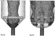
- FIGs 6a and 6b present the path of the light fluid phase 2 to be distributed in the heavy phase 4 coming from the duct 1, respectively in the case of the reference device ( figure 6a ), and in the case of the dispensing device according to the present description ( figure 6b ). For this, the iso volume of the percentage of gas from line 1 in the total gas phase between 10% and 100% is plotted.
- the distribution of the light fluid phase 2 coming from the pipe 1 is better with a covering of the majority of the reaction chamber 5.
- the light fluid phase 2 occupies about 80% of the volume above the distributor 3 against 30% for the reference device.
Landscapes
- Chemical & Material Sciences (AREA)
- Chemical Kinetics & Catalysis (AREA)
- Organic Chemistry (AREA)
- Engineering & Computer Science (AREA)
- Combustion & Propulsion (AREA)
- Oil, Petroleum & Natural Gas (AREA)
- General Chemical & Material Sciences (AREA)
- Devices And Processes Conducted In The Presence Of Fluids And Solid Particles (AREA)
- Feeding, Discharge, Calcimining, Fusing, And Gas-Generation Devices (AREA)
Applications Claiming Priority (1)
| Application Number | Priority Date | Filing Date | Title |
|---|---|---|---|
| FR1854921A FR3082125B1 (fr) | 2018-06-06 | 2018-06-06 | Dispositif de distribution de melange polyphasique dans une enceinte comportant un milieu fluidise |
Publications (1)
| Publication Number | Publication Date |
|---|---|
| EP3578253A1 true EP3578253A1 (de) | 2019-12-11 |
Family
ID=63963110
Family Applications (1)
| Application Number | Title | Priority Date | Filing Date |
|---|---|---|---|
| EP19175753.3A Withdrawn EP3578253A1 (de) | 2018-06-06 | 2019-05-21 | Ausgabevorrichtung eines mehrphasigen gemischs in einen behälter, der ein verflüssigtes milieu enthält |
Country Status (5)
| Country | Link |
|---|---|
| US (1) | US10507447B1 (de) |
| EP (1) | EP3578253A1 (de) |
| KR (1) | KR20190138748A (de) |
| FR (1) | FR3082125B1 (de) |
| RU (1) | RU2771134C2 (de) |
Families Citing this family (6)
| Publication number | Priority date | Publication date | Assignee | Title |
|---|---|---|---|---|
| US11266923B2 (en) * | 2019-04-24 | 2022-03-08 | Technip Process Technology, Inc. | Fluid distribution devices |
| WO2022204073A1 (en) | 2021-03-24 | 2022-09-29 | Chevron U.S.A. Inc. | Hydroconversion processes with ebullated bed reactors and inter-stage water addition |
| FR3123361A1 (fr) | 2021-05-31 | 2022-12-02 | IFP Energies Nouvelles | Dispositif et procédé de craquage catalytique avec apport de chaleur pour le traitement de charges peu cokantes. |
| FR3130287A1 (fr) | 2021-12-09 | 2023-06-16 | IFP Energies Nouvelles | Craquage catalytique de charges peu cokantes avec apport de chaleur par brûleur externe |
| FR3144024B1 (fr) | 2022-12-22 | 2025-07-04 | Ifp Energies Now | Distributeur pour lit fluidisé |
| CN116550254A (zh) * | 2023-04-18 | 2023-08-08 | 北京华能长江环保科技研究院有限公司 | 低温等离子体HgCl2连续发生装置 |
Citations (13)
| Publication number | Priority date | Publication date | Assignee | Title |
|---|---|---|---|---|
| US1673895A (en) * | 1926-07-23 | 1928-06-19 | Clive M Alexander | Bubble cap for gas and liquid contact apparatus |
| US1777869A (en) * | 1927-01-18 | 1930-10-07 | Clive M Alexander | Bubble cap for gas and liquid contact apparatus |
| EP0297762A1 (de) * | 1987-06-29 | 1989-01-04 | Uop | Vorrichtung zum Verteilen von Fluidisierungsgas |
| US5156817A (en) | 1990-05-15 | 1992-10-20 | Exxon Research And Engineering Company | Fccu regenerator catalyst distribution system |
| US5571482A (en) | 1992-04-27 | 1996-11-05 | Stone & Webster Engineering Corporation | Apparatus for controlling catalyst temperature during regeneration |
| US6221318B1 (en) | 1993-04-21 | 2001-04-24 | Shell Oil Company | Process and apparatus for distributing fluids in a container |
| US20040112831A1 (en) * | 1998-10-09 | 2004-06-17 | Rabie Hamid R. | Cyclic aeration system for submerged membrane modules |
| CN201154303Y (zh) * | 2008-02-01 | 2008-11-26 | 中国石化集团洛阳石油化工工程公司 | 一种气体进料分布器 |
| US20130041172A1 (en) * | 2010-04-30 | 2013-02-14 | Yusuke Ishii | Apparatus for removing catalyst surface substances |
| CN104014153A (zh) * | 2014-06-17 | 2014-09-03 | 南京德邦金属装备工程股份有限公司 | 一种微孔阀 |
| FR3006607A1 (fr) | 2013-06-11 | 2014-12-12 | Axens | Dispositif de distribution d'un fluide |
| WO2015153193A1 (en) * | 2014-03-31 | 2015-10-08 | Ineos Europe Ag | Feed sparger design for an ammoxidation reactor |
| CN107032303A (zh) * | 2017-06-15 | 2017-08-11 | 扬州惠通化工科技股份有限公司 | 过氧化氢的流化床生产系统及生产方法 |
Family Cites Families (5)
| Publication number | Priority date | Publication date | Assignee | Title |
|---|---|---|---|---|
| US3912460A (en) * | 1973-11-19 | 1975-10-14 | Texaco Development Corp | Method and article for distributing air in a regenerator |
| US4664888A (en) * | 1985-06-27 | 1987-05-12 | Texaco Inc. | Fluid catalytic cracking catalyst-vapor separator |
| DE3916325A1 (de) * | 1989-05-19 | 1990-11-22 | Grochowski Horst | Wanderbettreaktoranlage |
| BR0208964A (pt) * | 2001-04-20 | 2004-04-20 | Shell Int Research | Separador de ciclone, vaso reator, uso de um separador de ciclone, uso de um vaso reator, meio de retirada de partìcula sólida, e, uso de meio de retirada de partìcula sólida |
| RU2526837C1 (ru) * | 2013-05-23 | 2014-08-27 | Федеральное государственное унитарное предприятие "Государственный научный центр Российской Федерации-Физико-энергетический институт имени А.И. Лейпунского" | Распределительная камера |
-
2018
- 2018-06-06 FR FR1854921A patent/FR3082125B1/fr not_active Expired - Fee Related
-
2019
- 2019-05-21 EP EP19175753.3A patent/EP3578253A1/de not_active Withdrawn
- 2019-06-03 US US16/429,730 patent/US10507447B1/en active Active
- 2019-06-04 KR KR1020190065830A patent/KR20190138748A/ko active Pending
- 2019-06-05 RU RU2019117400A patent/RU2771134C2/ru active
Patent Citations (13)
| Publication number | Priority date | Publication date | Assignee | Title |
|---|---|---|---|---|
| US1673895A (en) * | 1926-07-23 | 1928-06-19 | Clive M Alexander | Bubble cap for gas and liquid contact apparatus |
| US1777869A (en) * | 1927-01-18 | 1930-10-07 | Clive M Alexander | Bubble cap for gas and liquid contact apparatus |
| EP0297762A1 (de) * | 1987-06-29 | 1989-01-04 | Uop | Vorrichtung zum Verteilen von Fluidisierungsgas |
| US5156817A (en) | 1990-05-15 | 1992-10-20 | Exxon Research And Engineering Company | Fccu regenerator catalyst distribution system |
| US5571482A (en) | 1992-04-27 | 1996-11-05 | Stone & Webster Engineering Corporation | Apparatus for controlling catalyst temperature during regeneration |
| US6221318B1 (en) | 1993-04-21 | 2001-04-24 | Shell Oil Company | Process and apparatus for distributing fluids in a container |
| US20040112831A1 (en) * | 1998-10-09 | 2004-06-17 | Rabie Hamid R. | Cyclic aeration system for submerged membrane modules |
| CN201154303Y (zh) * | 2008-02-01 | 2008-11-26 | 中国石化集团洛阳石油化工工程公司 | 一种气体进料分布器 |
| US20130041172A1 (en) * | 2010-04-30 | 2013-02-14 | Yusuke Ishii | Apparatus for removing catalyst surface substances |
| FR3006607A1 (fr) | 2013-06-11 | 2014-12-12 | Axens | Dispositif de distribution d'un fluide |
| WO2015153193A1 (en) * | 2014-03-31 | 2015-10-08 | Ineos Europe Ag | Feed sparger design for an ammoxidation reactor |
| CN104014153A (zh) * | 2014-06-17 | 2014-09-03 | 南京德邦金属装备工程股份有限公司 | 一种微孔阀 |
| CN107032303A (zh) * | 2017-06-15 | 2017-08-11 | 扬州惠通化工科技股份有限公司 | 过氧化氢的流化床生产系统及生产方法 |
Also Published As
| Publication number | Publication date |
|---|---|
| RU2771134C2 (ru) | 2022-04-26 |
| US10507447B1 (en) | 2019-12-17 |
| RU2019117400A3 (de) | 2021-11-29 |
| FR3082125B1 (fr) | 2021-05-21 |
| US20190374920A1 (en) | 2019-12-12 |
| FR3082125A1 (fr) | 2019-12-13 |
| RU2019117400A (ru) | 2020-12-07 |
| KR20190138748A (ko) | 2019-12-16 |
Similar Documents
| Publication | Publication Date | Title |
|---|---|---|
| FR3082125A1 (fr) | Dispositif de distribution de melange polyphasique dans une enceinte comportant un milieu fluidise | |
| FR3051375A1 (fr) | Dispositif de filtration et de distribution pour reacteur catalytique. | |
| EP3374073A1 (de) | Filterungs- und verteilungsvorrichtung für einen katalytischen reaktor | |
| EP0099800A1 (de) | Verfahren und Vorrichtung zur Wasserstoffbehandlung von Kohlenwasserstoffen in der Flüssigkeitsphase mit einem expandierten oder wallenden Katalysatorbett | |
| EP0960929B1 (de) | Verfahren und Vorrichtung zur Einführung von Katalysatorteilchen in einem katalytischen Wirbelschichtspaltungsreaktor | |
| EP3618947B1 (de) | Neue vorrichtung zum verteilen eines polyphasengemisches in einer kammer mit einem fluidisierten medium | |
| WO2018108751A1 (fr) | Procede de craquage catalytique de naphta avec compartimentage du reacteur en lit fluidise turbulent | |
| KR102608484B1 (ko) | 촉매 반응기용의 제거가능한 바스켓 | |
| FR2980720A1 (fr) | Plateau distributeur pour la distribution d'un melange polyphasique avec cheminees inclinees en peripherie. | |
| FR3094984A1 (fr) | Reacteur triphasique avec coupelle de recycle de section decroissante et d’angle d’inclinaison variable | |
| FR3144024A1 (fr) | Distributeur pour lit fluidisé | |
| EP3589396B1 (de) | Unterteilter reaktor mit niedriger kapazität | |
| FR3072302A1 (fr) | Dispositif comprenant des injections laterales de liquide pour limiter les phenomenes de depots solides dans les equipements a fond conique | |
| FR2980719A1 (fr) | Plateau distributeur pour la distribution d'un melange polyphasique avec cheminees tronquees en peripherie. | |
| EP2078558B1 (de) | Vorrichtung zur Verminderung des Aufprallgeschwindigkeitseffekts einer Fluide auf ein feststehendes Lager aus Festteilchen, mit einer solchen Vorrichtung ausgestatteter Reaktor und ihre Anwendungen | |
| FR3097139A1 (fr) | Reacteur triphasique a compartiments verticaux en serie avec separateurs intermediaires et procede d’hydroconversion de charges petrolieres lourdes | |
| EP3536398B1 (de) | Vorrichtung zur mischung eines fluides für einen katalytischen bett | |
| FR3081167A1 (fr) | Dispositif limitateur de vortex et de depots solides | |
| WO2018158015A1 (fr) | Reacteur comprenant des lits catalytiques de faible epaisseur | |
| EP4602136A1 (de) | Katalytisches fliessbett-crackverfahren mit gas-feststoff-gleichstromabwärtsfluss mit orientiertem zufuhrinjektor | |
| FR3140776A1 (fr) | Réacteur à lit fluidisé à co-courant gaz-solide descendant à écoulement homogène. | |
| EP3853525B1 (de) | Vorrichtung und verfahren zur chemical-looping-verbrennung mit einem partikelabscheider mit geneigtem einlasskanal | |
| EP4601779A1 (de) | Mischkammer für einen gas-feststoff-gleichstrom-abwärtsfluss-wirbelschichtreaktor | |
| US3085669A (en) | Transfer of granular solids | |
| FR3066410B1 (fr) | Dispositif de melange et de distribution avec zone de retournement |
Legal Events
| Date | Code | Title | Description |
|---|---|---|---|
| PUAI | Public reference made under article 153(3) epc to a published international application that has entered the european phase |
Free format text: ORIGINAL CODE: 0009012 |
|
| STAA | Information on the status of an ep patent application or granted ep patent |
Free format text: STATUS: THE APPLICATION HAS BEEN PUBLISHED |
|
| AK | Designated contracting states |
Kind code of ref document: A1 Designated state(s): AL AT BE BG CH CY CZ DE DK EE ES FI FR GB GR HR HU IE IS IT LI LT LU LV MC MK MT NL NO PL PT RO RS SE SI SK SM TR |
|
| AX | Request for extension of the european patent |
Extension state: BA ME |
|
| STAA | Information on the status of an ep patent application or granted ep patent |
Free format text: STATUS: REQUEST FOR EXAMINATION WAS MADE |
|
| 17P | Request for examination filed |
Effective date: 20200612 |
|
| RBV | Designated contracting states (corrected) |
Designated state(s): AL AT BE BG CH CY CZ DE DK EE ES FI FR GB GR HR HU IE IS IT LI LT LU LV MC MK MT NL NO PL PT RO RS SE SI SK SM TR |
|
| STAA | Information on the status of an ep patent application or granted ep patent |
Free format text: STATUS: EXAMINATION IS IN PROGRESS |
|
| 17Q | First examination report despatched |
Effective date: 20201124 |
|
| GRAP | Despatch of communication of intention to grant a patent |
Free format text: ORIGINAL CODE: EPIDOSNIGR1 |
|
| STAA | Information on the status of an ep patent application or granted ep patent |
Free format text: STATUS: GRANT OF PATENT IS INTENDED |
|
| INTG | Intention to grant announced |
Effective date: 20240709 |
|
| STAA | Information on the status of an ep patent application or granted ep patent |
Free format text: STATUS: THE APPLICATION IS DEEMED TO BE WITHDRAWN |
|
| 18D | Application deemed to be withdrawn |
Effective date: 20241112 |