EP3578472A2 - Tête de coupe et machine de coupe dotée d'une tête de coupe - Google Patents
Tête de coupe et machine de coupe dotée d'une tête de coupe Download PDFInfo
- Publication number
- EP3578472A2 EP3578472A2 EP19172387.3A EP19172387A EP3578472A2 EP 3578472 A2 EP3578472 A2 EP 3578472A2 EP 19172387 A EP19172387 A EP 19172387A EP 3578472 A2 EP3578472 A2 EP 3578472A2
- Authority
- EP
- European Patent Office
- Prior art keywords
- gripper
- cutting head
- strapping band
- strapping
- jaws
- Prior art date
- Legal status (The legal status is an assumption and is not a legal conclusion. Google has not performed a legal analysis and makes no representation as to the accuracy of the status listed.)
- Withdrawn
Links
- 238000005520 cutting process Methods 0.000 title claims abstract description 136
- 238000000034 method Methods 0.000 claims abstract description 6
- 238000012545 processing Methods 0.000 claims description 13
- 238000000926 separation method Methods 0.000 claims description 6
- 230000005540 biological transmission Effects 0.000 claims description 3
- 230000001105 regulatory effect Effects 0.000 claims description 3
- 230000002349 favourable effect Effects 0.000 description 17
- 239000003795 chemical substances by application Substances 0.000 description 10
- 238000010438 heat treatment Methods 0.000 description 4
- 238000013519 translation Methods 0.000 description 4
- 238000013461 design Methods 0.000 description 3
- 238000004519 manufacturing process Methods 0.000 description 3
- 238000005096 rolling process Methods 0.000 description 3
- 239000000523 sample Substances 0.000 description 3
- 230000006378 damage Effects 0.000 description 2
- 208000027418 Wounds and injury Diseases 0.000 description 1
- 238000010276 construction Methods 0.000 description 1
- 230000008878 coupling Effects 0.000 description 1
- 238000010168 coupling process Methods 0.000 description 1
- 238000005859 coupling reaction Methods 0.000 description 1
- 238000005265 energy consumption Methods 0.000 description 1
- 208000014674 injury Diseases 0.000 description 1
- 238000003754 machining Methods 0.000 description 1
- 238000005259 measurement Methods 0.000 description 1
- 230000003287 optical effect Effects 0.000 description 1
- 238000003860 storage Methods 0.000 description 1
Images






Classifications
-
- B—PERFORMING OPERATIONS; TRANSPORTING
- B65—CONVEYING; PACKING; STORING; HANDLING THIN OR FILAMENTARY MATERIAL
- B65B—MACHINES, APPARATUS OR DEVICES FOR, OR METHODS OF, PACKAGING ARTICLES OR MATERIALS; UNPACKING
- B65B69/00—Unpacking of articles or materials, not otherwise provided for
- B65B69/0025—Removing or cutting binding material, e.g. straps or bands
-
- B—PERFORMING OPERATIONS; TRANSPORTING
- B25—HAND TOOLS; PORTABLE POWER-DRIVEN TOOLS; MANIPULATORS
- B25J—MANIPULATORS; CHAMBERS PROVIDED WITH MANIPULATION DEVICES
- B25J11/00—Manipulators not otherwise provided for
- B25J11/005—Manipulators for mechanical processing tasks
- B25J11/0055—Cutting
-
- B—PERFORMING OPERATIONS; TRANSPORTING
- B25—HAND TOOLS; PORTABLE POWER-DRIVEN TOOLS; MANIPULATORS
- B25J—MANIPULATORS; CHAMBERS PROVIDED WITH MANIPULATION DEVICES
- B25J15/00—Gripping heads and other end effectors
- B25J15/0052—Gripping heads and other end effectors multiple gripper units or multiple end effectors
- B25J15/0061—Gripping heads and other end effectors multiple gripper units or multiple end effectors mounted on a modular gripping structure
-
- B—PERFORMING OPERATIONS; TRANSPORTING
- B25—HAND TOOLS; PORTABLE POWER-DRIVEN TOOLS; MANIPULATORS
- B25J—MANIPULATORS; CHAMBERS PROVIDED WITH MANIPULATION DEVICES
- B25J19/00—Accessories fitted to manipulators, e.g. for monitoring, for viewing; Safety devices combined with or specially adapted for use in connection with manipulators
- B25J19/02—Sensing devices
- B25J19/021—Optical sensing devices
- B25J19/022—Optical sensing devices using lasers
-
- B—PERFORMING OPERATIONS; TRANSPORTING
- B26—HAND CUTTING TOOLS; CUTTING; SEVERING
- B26D—CUTTING; DETAILS COMMON TO MACHINES FOR PERFORATING, PUNCHING, CUTTING-OUT, STAMPING-OUT OR SEVERING
- B26D1/00—Cutting through work characterised by the nature or movement of the cutting member or particular materials not otherwise provided for; Apparatus or machines therefor; Cutting members therefor
- B26D1/01—Cutting through work characterised by the nature or movement of the cutting member or particular materials not otherwise provided for; Apparatus or machines therefor; Cutting members therefor involving a cutting member which does not travel with the work
- B26D1/12—Cutting through work characterised by the nature or movement of the cutting member or particular materials not otherwise provided for; Apparatus or machines therefor; Cutting members therefor involving a cutting member which does not travel with the work having a cutting member moving about an axis
- B26D1/25—Cutting through work characterised by the nature or movement of the cutting member or particular materials not otherwise provided for; Apparatus or machines therefor; Cutting members therefor involving a cutting member which does not travel with the work having a cutting member moving about an axis with a non-circular cutting member
- B26D1/26—Cutting through work characterised by the nature or movement of the cutting member or particular materials not otherwise provided for; Apparatus or machines therefor; Cutting members therefor involving a cutting member which does not travel with the work having a cutting member moving about an axis with a non-circular cutting member moving about an axis substantially perpendicular to the line of cut
- B26D1/30—Cutting through work characterised by the nature or movement of the cutting member or particular materials not otherwise provided for; Apparatus or machines therefor; Cutting members therefor involving a cutting member which does not travel with the work having a cutting member moving about an axis with a non-circular cutting member moving about an axis substantially perpendicular to the line of cut with limited pivotal movement to effect cut
- B26D1/305—Cutting through work characterised by the nature or movement of the cutting member or particular materials not otherwise provided for; Apparatus or machines therefor; Cutting members therefor involving a cutting member which does not travel with the work having a cutting member moving about an axis with a non-circular cutting member moving about an axis substantially perpendicular to the line of cut with limited pivotal movement to effect cut for thin material, e.g. for sheets, strips or the like
-
- B—PERFORMING OPERATIONS; TRANSPORTING
- B26—HAND CUTTING TOOLS; CUTTING; SEVERING
- B26D—CUTTING; DETAILS COMMON TO MACHINES FOR PERFORATING, PUNCHING, CUTTING-OUT, STAMPING-OUT OR SEVERING
- B26D5/00—Arrangements for operating and controlling machines or devices for cutting, cutting-out, stamping-out, punching, perforating, or severing by means other than cutting
-
- B—PERFORMING OPERATIONS; TRANSPORTING
- B26—HAND CUTTING TOOLS; CUTTING; SEVERING
- B26D—CUTTING; DETAILS COMMON TO MACHINES FOR PERFORATING, PUNCHING, CUTTING-OUT, STAMPING-OUT OR SEVERING
- B26D5/00—Arrangements for operating and controlling machines or devices for cutting, cutting-out, stamping-out, punching, perforating, or severing by means other than cutting
- B26D5/02—Means for moving the cutting member into its operative position for cutting
- B26D5/06—Means for moving the cutting member into its operative position for cutting by electrical means
-
- B—PERFORMING OPERATIONS; TRANSPORTING
- B26—HAND CUTTING TOOLS; CUTTING; SEVERING
- B26D—CUTTING; DETAILS COMMON TO MACHINES FOR PERFORATING, PUNCHING, CUTTING-OUT, STAMPING-OUT OR SEVERING
- B26D5/00—Arrangements for operating and controlling machines or devices for cutting, cutting-out, stamping-out, punching, perforating, or severing by means other than cutting
- B26D5/08—Means for actuating the cutting member to effect the cut
- B26D5/086—Electric, magnetic, piezoelectric, electro-magnetic means
-
- B—PERFORMING OPERATIONS; TRANSPORTING
- B26—HAND CUTTING TOOLS; CUTTING; SEVERING
- B26D—CUTTING; DETAILS COMMON TO MACHINES FOR PERFORATING, PUNCHING, CUTTING-OUT, STAMPING-OUT OR SEVERING
- B26D1/00—Cutting through work characterised by the nature or movement of the cutting member or particular materials not otherwise provided for; Apparatus or machines therefor; Cutting members therefor
- B26D1/0006—Cutting members therefor
- B26D2001/0033—Cutting members therefor assembled from multiple blades
-
- B—PERFORMING OPERATIONS; TRANSPORTING
- B26—HAND CUTTING TOOLS; CUTTING; SEVERING
- B26D—CUTTING; DETAILS COMMON TO MACHINES FOR PERFORATING, PUNCHING, CUTTING-OUT, STAMPING-OUT OR SEVERING
- B26D7/00—Details of apparatus for cutting, cutting-out, stamping-out, punching, perforating, or severing by means other than cutting
- B26D2007/0012—Details, accessories or auxiliary or special operations not otherwise provided for
- B26D2007/0018—Trays, reservoirs for waste, chips or cut products
-
- B—PERFORMING OPERATIONS; TRANSPORTING
- B26—HAND CUTTING TOOLS; CUTTING; SEVERING
- B26D—CUTTING; DETAILS COMMON TO MACHINES FOR PERFORATING, PUNCHING, CUTTING-OUT, STAMPING-OUT OR SEVERING
- B26D7/00—Details of apparatus for cutting, cutting-out, stamping-out, punching, perforating, or severing by means other than cutting
- B26D2007/0012—Details, accessories or auxiliary or special operations not otherwise provided for
- B26D2007/0043—Details, accessories or auxiliary or special operations not otherwise provided for the cutting machine comprising a linear motor
Definitions
- the invention relates to a cutting head with at least one blade and a cutting machine with a cutting head.
- a cutting device for severing strapping bands placed around box stacks usually has a vertical gap over which the strapping bands are horizontal.
- the strapping band is searched for with a sensor in a vertical feed movement along this gap. If a strap is detected, this is detected with a hook on one side of the box stack and cut with a cutting element on the opposite side of the box stack.
- the strapping is passed from the hook to an extension, which subtracts the strapping from the stack of boxes.
- An object of the invention is to provide a cutting head for automated severing of strapping bands.
- Another object of the invention is to provide a cutting machine with a cutting head for automated severing of strapping bands.
- Another object of the invention is to provide a method of operating a cutting head for automated severing of strapping bands.
- the invention relates to a cutting head for a cutting machine, comprising at least one severing means and having a cooperating with the at least one severing means gripping device having at least one gripper for gripping a to be separated from the at least one severing strip strapping.
- the at least one separating means and the at least one gripper are designed as an integrated component and the at least one gripper has a pair of jaws which are arranged with its at least before grasping the strapping band on both sides of the strapping band and when closing the pair of jaws with a part of its jaws underneath Strapping band is arranged.
- the strapping band is positioned in this phase between the part of the pair of jaws which engages under the strapping band and the severing means.
- the strapping band may be lifted off the object surrounding it by the undergrip. Separation of the strapping band can therefore be carried out remotely from the surface of the object, whereby a risk of damage to the object can be reduced or avoided.
- the strapping band when closing the pair of jaws, can be clamped between the jaws. This facilitates a safe removal of the strap from the object.
- the at least one separating means may be a blade with at least one cutting edge.
- at least one element of the group heating wire, heating punch, ultrasonic device, laser beam can be used as a separating means, with which the strapping can be separated by mechanical and / or thermal means.
- a compact cutting head with which at least one separating means and the at least one gripping unit as integral components.
- a common feed movement of the at least one severing means and the at least one gripper to an object provided with the strapping band takes place from a single side of the object, for example by delivering the cutting head to the object with the strapping band.
- the cutting head can optionally be arranged on a robot arm or optionally on a linear drive, for example a so-called portal with linear drives with multiple axes, in particular for two or three axes (X-Y portal or X-Y-Z portal).
- the cutting head may also be provided stationarily mounted and an object, for example a package or a pallet, be moved past it with one or more strapping bands. The separated strapping can catch on the object and later be removed or optionally stripped with a scraper.
- strapping can be separated automatically and optionally deducted. On the one hand, this saves time, on the other hand, a risk of injury during the separation and removal of strapping bands, as may occur during manual removal, can be avoided.
- the cutting head is a compact component in which the corresponding components are integrated.
- the separating means integrated into the cutting head drives and components can be saved.
- the at least one separating means and the at least one gripper can be attached to a common base plate.
- the gripper can optionally be arranged movably along the base plate or optionally rigidly along the base plate. A movement of the at least one gripper along the base plate can take place along a Y-axis.
- the base plate may have a coupling for attachment to a robot arm.
- the severing agent is advantageously positioned on the gripper. Gripping and separating the strapping band can be performed consecutively or simultaneously.
- a severing means for example a blade
- a gripper by means of a relative movement between a severing means, for example a blade, and a gripper, a strapping band held in the gripper can be separated at the severing means.
- the severing agent at the same time sever the held strapping with the gripping of the strapping.
- the separating means for example the blade with its cutting edge, placed as close to the area of the gripper, which comes into contact with the strapping.
- the severing means for example the blade, can be delivered to the strapping band by means of a closing movement of the gripper, for instance by means of a mechanical translation.
- the strap can be automatically removed from the object that encloses it, in particular, be deducted.
- the severing agent can be immobile relative to the base plate and the gripper for separating the strapping this lead past the severing agent.
- the severing means for example the blade, can be moved towards the strapping band held in the gripper by a drive moving the severing means. The latter is favorable when a robot arm or a linear drive moves the cutting head as a whole along the X-axis to the strapping and out again.
- the separated strapping can be removed from the object in the gripper.
- a gripper can continue to hold the respective strapping band in place and grasp, separate and remove further strapping bands individually from the object.
- a storage or holding device for the withdrawn strapping band can be provided in the gripper, so that the gripper can be opened again.
- the removed straps can be removed from the gripper, collected and disposed of. If the cutting head has two or more grippers, two or all grippers can each separate and hold several strapping bands.
- the cutting head may experience movement along the Y axis.
- the gripper may be movable separately along the Y axis.
- the at least one gripper can be moved towards the strapping band.
- the gripper can be moved to the strapping by means of a feed drive, or the base plate can be moved with the gripper to the strapping.
- the relative movement between the severing means, such as a blade, and gripper is optionally along the X-axis.
- a blade as a severing means, its cutting edge can be transverse to the X-axis.
- a blade may be provided, the cutting edge is not transverse to the X-axis, but whose cutting edge is transverse to the Y-axis.
- the cutting edge can be perpendicular to the X or Y axis or inclined to this axis.
- the type of blade can be adapted to the strapping band to be separated. It may be provided with a straight edge blade.
- the blade edge may be inclined along the X-axis. Such an inclined cutting edge is favorable for separating the strapping band, as the blade is protected by avoiding punctiform loads.
- a round blade may be provided.
- the blade may be a V-shaped or curved blade which cuts like a pair of scissors.
- the jaws of the pair of jaws may have teeth which engage in the closing of the pair of jaws under the strapping.
- the teeth can interlock when closing the pair of jaws.
- the strapping band can thereby be lifted off the object. The strap can thus be separated without damaging the surface of the object.
- the cutting head may have a gripper feed drive for delivering the at least one gripper to the strapping band to be separated for severing the strapping band.
- a feed drive for delivering the at least one separating means to be separated on the strapping band for severing the strapping band may be provided.
- the at least one gripper can be moved with the gripper feed drive along the X-axis to the strapping band and away from it.
- the cutting head generally along the X-axis to the strapping band and be movable away from it.
- the severing means for example a blade
- the severing means is driven to move the severing agent along the X-axis, or the severing means, for example the blade, is mounted so that the severing means closes the gripper as it grips the strapping band separating strapping band.
- the separating means for example a blade
- the separating agent can be moved in the opposite direction.
- At least a part of the at least one gripper and the at least one severing means can be arranged to be movable relative to each other, so that when the relative movement between the part of the at least one gripper and the at least one severing means causes the strapping band to reach an area of action of the severing agent.
- This can be done by means of the gripper feed drive and / or by means of the feed drive for delivering the at least one separation means.
- the strapping band can then come into contact, for example, with a cutting edge or, depending on the selected severing agent, with a heating wire, a heating stamp, an ultrasonic device, a laser beam or the like.
- the gripper feed drive can move the gripper altogether.
- one or both jaws of the pair of jaws can have a ramp on which the strapping band can be moved away from the object when the jaws are closed, and as a result can reach the effective area of the rupture means.
- teeth of the pair of bowls can be chamfered accordingly, so that the strapping, when the part of the pair of jaws is arranged when closing the pair of jaws under the strapping, slides on the ramp and thus automatically moves away from the object.
- a sensor unit may be integrated in the cutting head, which detects a position of the strapping band to be separated relative to the cutting head and / or relative to the gripping device and / or relative to at least one gripper.
- the sensor unit may be arranged in advance with respect to the gripping device.
- the sensor unit may comprise an optical sensor, in particular a laser probe. This offers the possibility of making a precise distance measurement to the object that is surrounded by the strapping and to the strapping.
- the sensor unit may include an image recognition system that can identify a strapping tape by image recognition.
- the sensor unit may comprise a mechanical sensor in which a mechanical sensor sweeps over the object and detects the strapping band by means of a deflection.
- sensors units can be provided. Depending on the object to be processed, one or more suitable sensor units can be selected.
- the sensor unit can be further advantageously used to detect dimensions of the object, such as a carton or a pallet.
- a front edge and a rear edge of the object can be determined and thus a travel of the cutting head in the direction of the Y-axis are derived.
- the position of the strapping band to be separated on the object can be effected with at least one sensor unit which is integrated in the cutting head.
- at least one sensor unit may be provided away from the cutting head.
- a plurality of sensor units may be provided, which may all be integrated in the cutting head or of which at least one part may be provided separately in front of the cutting head.
- the sensor unit and the gripping device can be arranged on a common base plate. This allows a compact design of the cutting head.
- the gripping device may comprise at least two grippers. This is advantageous if at least two strapping bands or else several strapping bands are present on the object.
- the at least two grippers can be provided arranged at a constant distance from each other. This is advantageous if several strapping bands are to be pulled off an object.
- the at least two grippers may be provided arranged at a variable distance from each other.
- the cutting head can be flexibly adapted to different distances of strapping bands and different sizes of objects with strapping bands.
- a corresponding linear drive for one, two or more grippers can be arranged so that the distance can be changed during the processing of objects.
- the gripping device may be provided arranged at a constant distance from the sensor unit. This allows a compact, inexpensive design of the cutting head.
- the gripping device may be provided at least in regions arranged at a variable distance from the sensor unit.
- the at least one separating means may be provided arranged in the feed direction of the gripper feed drive in a constant position. This is a cost-effective variant, since a separate drive for the at least one separating means can be dispensed with. Likewise, weight can be saved on the cutting head and the energy consumption can be reduced.
- the separation of the strapping can be done reliably when retracting the gripper with the strapping gripped strap from the object.
- the at least one separating means may be provided arranged in the feed direction of the gripper feed drive in a variable position. This allows a higher flexibility of the cutting head.
- a data transmission device can be provided, with which a position of the strapping band to be separated from the at least one severing means can be transmitted to a control and / or regulating device.
- the data transmission device may comprise a cable and / or a transceiver device or the like. The finding, gripping, separating and removing the strapping can be done fully automatically.
- a cutting machine is proposed with at least one cutting head according to the invention.
- the cutting machine has at least one first processing station, wherein the cutting head is arranged on the at least one first processing station.
- the processing station can be manually loaded by placing an object, such as a pallet or carton, with one or more strapping bands in the processing station.
- a conveyor belt can be provided, on which the object or objects is transported to the processing station with the cutting head.
- a fixing device is provided, with which the object is fixed in the machining position, in particular clamped.
- a collecting device may be provided for collecting strapping bands severed by the at least one cutting head.
- the straps can be easily disposed of and / or reprocessed.
- a crushing plant can be provided, in which the stripped strapping ribbons are comminuted and thus compactly collected.
- the at least one cutting head can be fastened to a robot arm.
- the arrangement saves space. Furthermore, due to its many degrees of freedom, a robot arm can be surrounded on several sides by objects with strapping bands which can be processed by the robot arm.
- the at least one cutting head can be fastened to an X-Y portal or X-Y-Z portal.
- the cutting head can be moved with a corresponding linear drive, for example in the direction of an X-axis and in the direction of a Y-axis to the strapping band to be separated.
- the object may be moved toward the cutting head.
- the sensor unit can in each case recognize the position of the object and the at least one strapping band and forward it to the regulating and / or control device.
- the gripping and severing of the strapping band can be done in time sequence or virtually simultaneously.
- the relative movement between the gripper and the severing means can take place along the X axis, in that the severing means is rigid and the gripper is movable and / or in that the severing means is movable and the gripper is rigid.
- the gripper can move the severing means, for example a blade, along the X-axis when the gripper is closed, by providing a mechanical translation, for example on pairs of jaws of the gripper, and the severing means, for example the blade, via a rolling movement along the X-axis. Axis is moved.
- the separating agent can be moved in the opposite direction.
- the position of the strapping band to be separated can be effected with a sensor unit which is integrated in the cutting head.
- the sensor unit may be remote from the cutting head.
- a plurality of sensor units may be provided, which may all be integrated in the cutting head or of which at least one part may be provided separately in front of the cutting head.
- a processing of objects such as boxes and / or pallets, are to be deducted in the strapping of the objects, automated quickly and reliably done with a compact tool.
- FIG. 1 shows a front view of a cutting head 10 with a sensor unit 90 and a gripping device 20 with a gripper 22 according to an embodiment of the invention, wherein the gripper 22 with a feed drive 26 along an X-axis to an object which is surrounded by a strapping 112, driven is.
- the X-axis corresponds to a vertical axis, for example.
- FIG. 2 shows a side view of the cutting head 10 after FIG. 1 ,
- the cutting head 10 has a pair of jaws 24 which extend by a length 28 in Direction of a Z-axis extends.
- the Z-axis here corresponds to a transverse axis.
- the strapping band extends in the area in which it is to be separated, substantially in the direction of the Z-axis.
- the length 28 is dimensioned so that a strapping in the pair of jaws can be securely held over a corresponding longitudinal section.
- the Y-axis corresponds for example to a longitudinal axis.
- FIGS. 3 to 6 show a further embodiment of the invention similar as in the Figures 1 and 2 wherein the gripper 22 of the gripping device 20 has no feed drive, which moves it along the X-axis, but is rigid with respect to the X-axis.
- the cutting head 10 is arranged on a robot arm or a portal with feed drive for the cutting head 10.
- FIG. 3 shows a perspective view of the cutting head 10 on a provided with straps 112, 114 object in the form of a carton 110 in a cutting station 100th
- FIG. 3 1 shows the cutting head 10 above a cardboard 110 provided with strapping bands 112, 114 in a processing station 150 of a cutting machine 100.
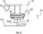
- FIGS. 4 to 6 illustrate a sequence of steps in removing a strapping tape 112 from an object in the form of a carton 110 by means of the cutting head 10 FIG. 1 after delivery of the gripper 22 to the strapping band 112 (FIG. FIG. 4 ), when gripping the strapping band 112 (FIG. FIG. 5 ) and when lifting and separating the strapping band 112 (FIG. FIG. 6 ).
- Gripper 22 and sensor unit 90 in this example a laser probe, are arranged on a common base plate 12.
- the sensor unit 90 directs two converged laser beams, shown in broken lines, onto an object in the form of a carton 110 surrounded by one or more strapping bands 112.
- the laser probe can detect the distance to the object with high accuracy and forward the data to a control and / or control unit 120 (FIG. FIG. 3 ).
- the control and / or control unit 120 for example, a robot arm on which the cutting head 10 is arranged or a portal with linear drives for two or three axes in which the cutting head 10 is mounted, control.
- the cutting head 10 has an X-axis, a Y-axis and a Z-axis, which are perpendicular to each other.
- the cutting head 10 moves along the Y-axis when the sensor unit 90 scans the object for a strapping 112.
- the sensor unit 90 can detect the beginning and end of the object, ie its longitudinal extent along the Y-axis.
- the strap 112 is removed from the gripper 22 in the X-axis direction.
- the gripper 22 is equipped, for example, with a pair of jaws 24, between which the strapping band 112 can be gripped.
- a closing drive 30 close the jaws of the pair of jaws 24, so that the strapping 112 is clamped in the pair of jaws 24. If necessary, the closing drive 30, the pair of jaws 24 open again.
- the jaws of the pair of jaws 24 are formed like a comb with teeth 25 ( FIG. 2 ), so that the jaws mesh with the comb structure and can clamp the strap 112.
- the jaws of the pair of jaws 24 extend through the comb-like configuration of the jaws with the length in the direction of the Z-axis 28, so that the strap 112 can be clamped securely on a sufficient portion between the jaws.
- a blade 51 is arranged, which has an oblique cutting edge in this example.
- the blade 51 may for example be provided fixedly relative to the base plate 12.
- the gripper 22 of the gripping device 20 is placed above the strapping band 112. Then the gripper 22 is applied to the strapping band 112 ( FIG. 4 ). Before gripping the strapping band 112, the jaws of the pair of jaws 24 with the teeth 25 are placed on the left and right sides of the two narrow sides of the strapping band 112.
- the strap 112 is gripped by the gripper 22 and clamped in the pair of jaws 24 ( FIG. 5 ).
- the pair of jaws 24 with the teeth 25 of its jaws grip from both sides under the strapping 112.
- a feed drive 26 may be provided to move the gripper 22 along the X-axis.
- the withdrawn straps 112 may be collected and disposed of in a collector 160 (FIG. FIG. 3 ).
- FIGS. 7 to 18 show a further embodiment of the invention, wherein FIG. 8 a variant of a cutting head 10 from FIG. 7 shows.
- FIG. 7 shows a front view of a cutting head 10 with a sensor unit 90 and a gripping device 20 with two grippers 22, 32 according to a further embodiment of the invention, which have a fixed distance from each other.
- FIG. 8 shows a front view of a cutting head 10 with a sensor unit 90 and a gripping device 20 with two grippers 22, 32 according to another embodiment of the invention, wherein the grippers 22, 32 are mutually displaceable to vary their mutual distance, which by a wide double arrow under the base plate 12 is indicated.
- These variants are advantageous when on an object ( FIGS. 9 to 18 ) two or more strapping bands 112, 114 to be separated are arranged ( FIGS. 9 to 18 ).
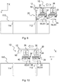
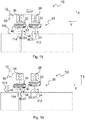
- FIGS. 9 to 18 10 show a sequence of method steps when removing strapping bands 112, 114 from an object in the form of a carton 110 with two strapping bands 112, 114 by means of a cutting head 10 FIG. 7 ,
- a blade 51 and behind the gripper 32 as a severing means 60 a blade 61 are arranged, which in this example each have an oblique cutting edge.
- the blades 51, 61 may for example be provided fixedly relative to the base plate 12.
- the first gripper 22 is equipped, for example, with a pair of jaws 24 and the second gripper 32 with a pair of jaws 34, between which the strapping band 112, 114 can be gripped.
- a closing drive 30, the jaws of the pair of jaws 24 and a closing drive 40 close the jaws of the pair of jaws 34, so that the respective strapping 112, 114 is clamped in the respective pair of jaws 24, 34.
- the closing drive 30, 40, the pair of jaws 24, 34 open again.
- the jaws of the pair of jaws 24, 34 may be formed like a comb with teeth 25, 35 as in the embodiment described above.
- the first gripper 22 After finding and detecting the position of the first strapping band 112 on the carton 110 by the sensor unit 90 (FIG. FIG. 9 ), the first gripper 22 is placed above the strapping band ( FIG. 10 ), the gripper 22 is applied to the strapping band ( FIG. 11 ), the strapping band gripped by the gripper 22 and clamped in the pair of jaws 24 ( FIG. 12 ).
- a feed drive 26 may be provided to move the gripper 22 along the X-axis.
- the cutting head 10 continues to move along the Y-axis ( FIG. 14 ) until the sensor unit 90 detects another strap 114.
- the clamped in the first gripper 22 strapping 112 is taken along.
- the second gripper 32 After finding and recognizing the position of the further strapping tape 114 on the cardboard 110 by the sensor unit 90, the second gripper 32 is placed above the further strapping tape 114 (FIG. FIG. 15 ), the gripper 32 is applied to the strapping band ( FIG. 16 ), the strapping band gripped by the gripper 32 and clamped in the pair of jaws 34 ( FIG. 17 ).
- a feed drive 36 may be provided to move the gripper 32 along the X-axis.
- a sensor unit 90 is provided. It is understood that a plurality of sensor units 90 may be provided. Further, the sensor unit 90 in the embodiments on the base plate 12 arranged. It is understood that the cutting head 10 has no sensor unit 90, but one or more sensor unit 90 may be provided separately from the cutting head 10. Furthermore, provision may be made to provide sensor units 90 both on the cutting head 10 and separately from the cutting head 10.
- the blade 51, 61 can be provided to rigidly arrange the blade 51, 61 along the X-axis, or to provide a drive for the blade 51, 61.
- a mechanical translation with a rolling curve can be provided on the gripper 22, 32, which delivers the blade 51, 61 to the strapping 112, 114 when closing the pair of jaws 24, 34 and 34 when opening the pair of jaws 24, 34 removed from the strapping 112, 114.
Landscapes
- Engineering & Computer Science (AREA)
- Mechanical Engineering (AREA)
- Life Sciences & Earth Sciences (AREA)
- Forests & Forestry (AREA)
- Robotics (AREA)
- Physics & Mathematics (AREA)
- Optics & Photonics (AREA)
- Basic Packing Technique (AREA)
- Control And Other Processes For Unpacking Of Materials (AREA)
Applications Claiming Priority (1)
| Application Number | Priority Date | Filing Date | Title |
|---|---|---|---|
| DE102018113490.8A DE102018113490A1 (de) | 2018-06-06 | 2018-06-06 | Schneidkopf und Schneidmaschine mit einem Schneidkopf |
Publications (2)
| Publication Number | Publication Date |
|---|---|
| EP3578472A2 true EP3578472A2 (fr) | 2019-12-11 |
| EP3578472A3 EP3578472A3 (fr) | 2020-03-11 |
Family
ID=66397049
Family Applications (1)
| Application Number | Title | Priority Date | Filing Date |
|---|---|---|---|
| EP19172387.3A Withdrawn EP3578472A3 (fr) | 2018-06-06 | 2019-05-02 | Tête de coupe et machine de coupe dotée d'une tête de coupe |
Country Status (2)
| Country | Link |
|---|---|
| EP (1) | EP3578472A3 (fr) |
| DE (1) | DE102018113490A1 (fr) |
Cited By (6)
| Publication number | Priority date | Publication date | Assignee | Title |
|---|---|---|---|---|
| CN111070285A (zh) * | 2019-12-31 | 2020-04-28 | 佛山景日自动化科技有限公司 | 一种纺丝自动加工装置的电控系统 |
| IT202100001493A1 (it) * | 2021-01-26 | 2022-07-26 | Denken Italia S R L | Dispositivo per la rimozioni di parti danneggiate di un pallet |
| US11485104B2 (en) | 2019-02-07 | 2022-11-01 | Bhs Intralogistics Gmbh | Material roll preparation arrangement |
| CN115535403A (zh) * | 2022-11-03 | 2022-12-30 | 红云红河烟草(集团)有限责任公司 | 云烟制丝专线片烟烟箱柔性解包装置 |
| EP4382438A1 (fr) * | 2022-12-05 | 2024-06-12 | TITAN Umreifungstechnik GmbH & Co.KG | Dispositif de cerclage et procédé de traitement d'un lien de cerclage |
| EP4603240A1 (fr) * | 2024-02-15 | 2025-08-20 | Sidel Participations | Chariot coupe lien et procédé de découpe d'un lien |
Citations (1)
| Publication number | Priority date | Publication date | Assignee | Title |
|---|---|---|---|---|
| DE10205462C1 (de) | 2002-02-08 | 2003-09-11 | R S T Roboter System Technik G | Vorrichtung zum Entfernen einer Umschnürung von einem Kastenstapel |
Family Cites Families (11)
| Publication number | Priority date | Publication date | Assignee | Title |
|---|---|---|---|---|
| DE3411030A1 (de) * | 1984-03-24 | 1985-09-26 | Alfons 8301 Eggmühl Holmer | Ballendrahtschneider |
| DE8609063U1 (de) * | 1986-04-04 | 1986-05-22 | Sundwiger Eisenhütte Maschinenfabrik GmbH & Co, 58675 Hemer | Vorrichtung zum Öffnen und Verschrotten von Umreifungsbändern an einem Packstück |
| FR2599291A1 (fr) * | 1986-05-28 | 1987-12-04 | Benet Jacques | Machine pour le sectionnement des liens entourant des colis notamment des bobines et paquets de toles |
| IT1252418B (it) * | 1991-07-11 | 1995-06-14 | Gd Spa | Apparecchiatura per tagliare le cordelle di contenimento di prodotti trasportati su supporti a pallet |
| US5467676A (en) * | 1991-08-13 | 1995-11-21 | Lamb-Grays Harbor Co. | Automatic roll wrapper removing apparatus and method |
| DE9411292U1 (de) * | 1994-06-16 | 1995-01-05 | Weck, Werner, Dipl.-Ing., 50129 Bergheim | Anlage zur kontinuierlichen Entreifung von Kartons |
| DE19512344A1 (de) * | 1995-04-01 | 1996-10-02 | Doornkaat Verwaltung Ag | Vorrichtung zur Auflösung eines durch bandförmiges Material zusammengehaltenen Verbundes aus Artikeln, vorzugsweise Getränkebehältnissen wie Flaschen |
| DE19607537C1 (de) * | 1996-02-28 | 1997-07-03 | Lamb Ag | Auspackmaschine für Rollen, insbesondere Druckpapierrollen |
| DE19812575A1 (de) * | 1998-03-21 | 1999-09-23 | Helmut Kuemmerer | Vorrichtung zum Entschnüren eines Behälterstapels |
| DE102012002313B4 (de) * | 2012-02-06 | 2014-04-24 | Jörg Lange | Bandschneider |
| CN107487581B (zh) * | 2017-06-15 | 2019-04-12 | 亚杰科技(江苏)有限公司 | 一套打包带收集设备 |
-
2018
- 2018-06-06 DE DE102018113490.8A patent/DE102018113490A1/de not_active Withdrawn
-
2019
- 2019-05-02 EP EP19172387.3A patent/EP3578472A3/fr not_active Withdrawn
Patent Citations (1)
| Publication number | Priority date | Publication date | Assignee | Title |
|---|---|---|---|---|
| DE10205462C1 (de) | 2002-02-08 | 2003-09-11 | R S T Roboter System Technik G | Vorrichtung zum Entfernen einer Umschnürung von einem Kastenstapel |
Cited By (7)
| Publication number | Priority date | Publication date | Assignee | Title |
|---|---|---|---|---|
| US11485104B2 (en) | 2019-02-07 | 2022-11-01 | Bhs Intralogistics Gmbh | Material roll preparation arrangement |
| CN111070285A (zh) * | 2019-12-31 | 2020-04-28 | 佛山景日自动化科技有限公司 | 一种纺丝自动加工装置的电控系统 |
| IT202100001493A1 (it) * | 2021-01-26 | 2022-07-26 | Denken Italia S R L | Dispositivo per la rimozioni di parti danneggiate di un pallet |
| CN115535403A (zh) * | 2022-11-03 | 2022-12-30 | 红云红河烟草(集团)有限责任公司 | 云烟制丝专线片烟烟箱柔性解包装置 |
| EP4382438A1 (fr) * | 2022-12-05 | 2024-06-12 | TITAN Umreifungstechnik GmbH & Co.KG | Dispositif de cerclage et procédé de traitement d'un lien de cerclage |
| EP4603240A1 (fr) * | 2024-02-15 | 2025-08-20 | Sidel Participations | Chariot coupe lien et procédé de découpe d'un lien |
| FR3159381A1 (fr) * | 2024-02-15 | 2025-08-22 | Sidel Participations | Chariot coupe lien et procédé de découpe d’un lien |
Also Published As
| Publication number | Publication date |
|---|---|
| EP3578472A3 (fr) | 2020-03-11 |
| DE102018113490A1 (de) | 2019-12-12 |
Similar Documents
| Publication | Publication Date | Title |
|---|---|---|
| EP3578472A2 (fr) | Tête de coupe et machine de coupe dotée d'une tête de coupe | |
| DE69000287T2 (de) | Vorrichtung zum zufuehren von stapeln bogenfoermigen materials in eine verpackungsmaschine. | |
| EP2520500B1 (fr) | Station de découpage avec unité de découpage | |
| EP3024355B1 (fr) | Poste de transfert pour le transfert de filaments de soie | |
| DE3243906A1 (de) | Riemenfoerderer fuer den transport von drahtstuecken | |
| EP2736810A2 (fr) | Dispositif et procédé de déballage et d'amenée d'emballages de conditionnement pliés à plat et debout | |
| EP2759482A1 (fr) | Dispositif d'élimination des matériaux liants sur des emballages | |
| EP3431422B1 (fr) | Dispositif de préhension pour un manipulateur et procédé d'équipement d'un dispositif de préhension pour un manipulateur | |
| DE10355544B4 (de) | Verfahren und Vorrichtung für die Übergabe von Zuschnitten aus Umkartons an eine Weiterverarbeitungseinheit | |
| DE19752452A1 (de) | Drahtschneid- und Abisoliermechanismus | |
| EP3566985B1 (fr) | Dispositif d'empilement de plateaux pourvu d'un moyen de décharge | |
| EP1079479B1 (fr) | Dispositif pour déposer des câbles | |
| EP2894017B1 (fr) | Procédé d'application d'un chemin de coupe et dispositif d'application d'un chemin de coupe | |
| EP3581508B1 (fr) | Dispositif de séparation pour bandes de cerclage | |
| DE2855138C2 (de) | Vorrichtung zum Abschneiden eines Haltebandes | |
| DE69409017T2 (de) | Zuführgerät eines Handhabungssystems für Gegenstände | |
| DE102010017572A1 (de) | Greifapparat | |
| DE4029759A1 (de) | Ballentransportmittel fuer faserballen | |
| EP3071488B1 (fr) | Outil robot pour la elimination automatique d'enrubanages de balles | |
| DE60104095T2 (de) | Anlage zum schneiden und verpacken von brot | |
| DE10149043C1 (de) | Verfahren und Vorrichtung zum Herstellen von Bürsten, insbesondere Zahnbürsten | |
| EP4382438B1 (fr) | Dispositif de cerclage et procédé de traitement d'un lien de cerclage | |
| EP3751033B1 (fr) | Ourdissoir sectionnel à cône et procédé de fonctionnement d'un ourdissoir sectionnel à cône | |
| EP4516415A1 (fr) | Machine et procédé de tri d'asperges, ainsi que dispositif de prélèvement | |
| WO1990000499A1 (fr) | Dispositif avec cadre d'elimination d'enrubanages de balles comprimees |
Legal Events
| Date | Code | Title | Description |
|---|---|---|---|
| PUAI | Public reference made under article 153(3) epc to a published international application that has entered the european phase |
Free format text: ORIGINAL CODE: 0009012 |
|
| STAA | Information on the status of an ep patent application or granted ep patent |
Free format text: STATUS: THE APPLICATION HAS BEEN PUBLISHED |
|
| AK | Designated contracting states |
Kind code of ref document: A2 Designated state(s): AL AT BE BG CH CY CZ DE DK EE ES FI FR GB GR HR HU IE IS IT LI LT LU LV MC MK MT NL NO PL PT RO RS SE SI SK SM TR |
|
| AX | Request for extension of the european patent |
Extension state: BA ME |
|
| PUAL | Search report despatched |
Free format text: ORIGINAL CODE: 0009013 |
|
| AK | Designated contracting states |
Kind code of ref document: A3 Designated state(s): AL AT BE BG CH CY CZ DE DK EE ES FI FR GB GR HR HU IE IS IT LI LT LU LV MC MK MT NL NO PL PT RO RS SE SI SK SM TR |
|
| AX | Request for extension of the european patent |
Extension state: BA ME |
|
| RIC1 | Information provided on ipc code assigned before grant |
Ipc: B65B 69/00 20060101AFI20200131BHEP Ipc: B25J 11/00 20060101ALI20200131BHEP |
|
| STAA | Information on the status of an ep patent application or granted ep patent |
Free format text: STATUS: THE APPLICATION IS DEEMED TO BE WITHDRAWN |
|
| 18D | Application deemed to be withdrawn |
Effective date: 20200912 |