EP3578490A1 - Klebebandapplikator mit schwenkbarer umlenkkanteneinheit - Google Patents
Klebebandapplikator mit schwenkbarer umlenkkanteneinheit Download PDFInfo
- Publication number
- EP3578490A1 EP3578490A1 EP19175369.8A EP19175369A EP3578490A1 EP 3578490 A1 EP3578490 A1 EP 3578490A1 EP 19175369 A EP19175369 A EP 19175369A EP 3578490 A1 EP3578490 A1 EP 3578490A1
- Authority
- EP
- European Patent Office
- Prior art keywords
- adhesive tape
- umlenkkanteneinheit
- applicator
- application
- applicator head
- Prior art date
- Legal status (The legal status is an assumption and is not a legal conclusion. Google has not performed a legal analysis and makes no representation as to the accuracy of the status listed.)
- Granted
Links
Images



Classifications
-
- B—PERFORMING OPERATIONS; TRANSPORTING
- B65—CONVEYING; PACKING; STORING; HANDLING THIN OR FILAMENTARY MATERIAL
- B65H—HANDLING THIN OR FILAMENTARY MATERIAL, e.g. SHEETS, WEBS, CABLES
- B65H37/00—Article or web delivery apparatus incorporating devices for performing specified auxiliary operations
- B65H37/002—Web delivery apparatus, the web serving as support for articles, material or another web
- B65H37/005—Hand-held apparatus
-
- B—PERFORMING OPERATIONS; TRANSPORTING
- B65—CONVEYING; PACKING; STORING; HANDLING THIN OR FILAMENTARY MATERIAL
- B65H—HANDLING THIN OR FILAMENTARY MATERIAL, e.g. SHEETS, WEBS, CABLES
- B65H23/00—Registering, tensioning, smoothing or guiding webs
- B65H23/04—Registering, tensioning, smoothing or guiding webs longitudinally
- B65H23/26—Registering, tensioning, smoothing or guiding webs longitudinally by transverse stationary or adjustable bars or rollers
-
- B—PERFORMING OPERATIONS; TRANSPORTING
- B65—CONVEYING; PACKING; STORING; HANDLING THIN OR FILAMENTARY MATERIAL
- B65H—HANDLING THIN OR FILAMENTARY MATERIAL, e.g. SHEETS, WEBS, CABLES
- B65H16/00—Unwinding, paying-out webs
- B65H16/005—Dispensers, i.e. machines for unwinding only parts of web roll
-
- B—PERFORMING OPERATIONS; TRANSPORTING
- B65—CONVEYING; PACKING; STORING; HANDLING THIN OR FILAMENTARY MATERIAL
- B65H—HANDLING THIN OR FILAMENTARY MATERIAL, e.g. SHEETS, WEBS, CABLES
- B65H35/00—Delivering articles from cutting or line-perforating machines; Article or web delivery apparatus incorporating cutting or line-perforating devices, e.g. adhesive tape dispensers
- B65H35/0006—Article or web delivery apparatus incorporating cutting or line-perforating devices
- B65H35/002—Hand-held or table apparatus
- B65H35/0026—Hand-held or table apparatus for delivering pressure-sensitive adhesive tape
-
- B—PERFORMING OPERATIONS; TRANSPORTING
- B65—CONVEYING; PACKING; STORING; HANDLING THIN OR FILAMENTARY MATERIAL
- B65H—HANDLING THIN OR FILAMENTARY MATERIAL, e.g. SHEETS, WEBS, CABLES
- B65H35/00—Delivering articles from cutting or line-perforating machines; Article or web delivery apparatus incorporating cutting or line-perforating devices, e.g. adhesive tape dispensers
- B65H35/0006—Article or web delivery apparatus incorporating cutting or line-perforating devices
- B65H35/002—Hand-held or table apparatus
- B65H35/0026—Hand-held or table apparatus for delivering pressure-sensitive adhesive tape
- B65H35/0033—Hand-held or table apparatus for delivering pressure-sensitive adhesive tape and affixing it to a surface
-
- B—PERFORMING OPERATIONS; TRANSPORTING
- B65—CONVEYING; PACKING; STORING; HANDLING THIN OR FILAMENTARY MATERIAL
- B65H—HANDLING THIN OR FILAMENTARY MATERIAL, e.g. SHEETS, WEBS, CABLES
- B65H35/00—Delivering articles from cutting or line-perforating machines; Article or web delivery apparatus incorporating cutting or line-perforating devices, e.g. adhesive tape dispensers
- B65H35/0006—Article or web delivery apparatus incorporating cutting or line-perforating devices
- B65H35/0073—Details
-
- B—PERFORMING OPERATIONS; TRANSPORTING
- B65—CONVEYING; PACKING; STORING; HANDLING THIN OR FILAMENTARY MATERIAL
- B65H—HANDLING THIN OR FILAMENTARY MATERIAL, e.g. SHEETS, WEBS, CABLES
- B65H2701/00—Handled material; Storage means
- B65H2701/30—Handled filamentary material
- B65H2701/37—Tapes
- B65H2701/377—Adhesive tape
-
- Y—GENERAL TAGGING OF NEW TECHNOLOGICAL DEVELOPMENTS; GENERAL TAGGING OF CROSS-SECTIONAL TECHNOLOGIES SPANNING OVER SEVERAL SECTIONS OF THE IPC; TECHNICAL SUBJECTS COVERED BY FORMER USPC CROSS-REFERENCE ART COLLECTIONS [XRACs] AND DIGESTS
- Y10—TECHNICAL SUBJECTS COVERED BY FORMER USPC
- Y10T—TECHNICAL SUBJECTS COVERED BY FORMER US CLASSIFICATION
- Y10T156/00—Adhesive bonding and miscellaneous chemical manufacture
- Y10T156/17—Surface bonding means and/or assemblymeans with work feeding or handling means
- Y10T156/1788—Work traversing type and/or means applying work to wall or static structure
- Y10T156/1795—Implement carried web supply
Definitions
- the invention relates to an adhesive tape applicator with a receptacle for an adhesive tape roll and at least one handle and a positionally fixed relative to the handle arranged applicator head.
- the adhesive tape consists of a carrier equipped on one side with an adhesive layer, the adhesive mass of which is covered by a strip of separating material.
- the tape dispenser allows the release strip to be automatically released from the adhesive layer of the carrier during the application process. Also disadvantageous of this adhesive tape dispenser is that on the one hand a guided application of the adhesive tape along one edge is very difficult and, on the other hand, a handle directed in the direction of application hinders the application in the direction of application.
- the doors are not yet provided with an inner lining and also not yet with seals, so that a gap of a few millimeters wide between the door and a roof.
- a gap forms along the front door between the A and B pillars and along the back door between the B and C pillars along the entire roof pillar.
- the Umlenkkantentician is arranged rotatably about a longitudinal axis relative to the applicator head, and the Umlenkkantenhow is coupled by means of a spring with the applicator head, which presses the Umlenkkantenhow in a neutral position relative to the applicator head.
- the neutral position is an angular position which is smaller than the smallest outer angle between the lateral contact side and application side of the profile to be glued, in particular roof rail, of a motor vehicle.
- a receptacle has a mandrel aligned in the application direction, onto which the adhesive tape roll can be inserted, wherein the adhesive tape can be fed to the applicator head about at least one, preferably two, deflection rollers. It is also conceivable any higher number of pulleys.
- the adhesive tape applicator comprises a base unit 9 and the applicator head 7 arranged exchangeably on the base unit 9.
- the base unit 9 comprises the receptacle 1 for the adhesive tape roll 2 with a mandrel arranged at its free end onto which the adhesive tape roll 2 can be placed and a block 11 the recording 1 is fixed in a fixed position.
- the applicator head 7 opposite at least one handle 12 is fixedly positioned relative to the block 11.
- the handle 12 is attached to a plate 13, which in turn is attached to the block 11.
- the two deflection rollers 4, 6 are arranged laterally opposite the block 11, so as to be rotatable.
- the deflection edge unit 8 has an application side 14, which in Fig. 1 is arranged on top of the Umlenkkantentician 8. Along the application side 14, a longitudinal groove 16 is provided. In the longitudinal groove 16 is an in Fig. 1 non-illustrated Andschreibklebeband 17 glued.
- the pressure-sensitive adhesive tape 17 is a foam adhesive tape having a width which corresponds to a width B of the longitudinal groove 16.
- the Andschreibklebeband 17 extends along a portion of the longitudinal extent of the longitudinal groove 16 and is glued into the longitudinal groove 16.
- On a free, longitudinal groove 16 facing away from the outside of Andrückklebebands 17, a friction-reducing layer may be applied.
- Fig. 2 shows in a review of the Umlenkkantentician 8 the detailed structure of the Umlenkkantentician 8.
- the in Fig. 2 No longer shown adhesive tape 3 is around the first guide roller 4 and following in a stripping direction second guide roller 6 according to Fig. 1 guided.
- the adhesive tape 3 is guided below the deflection edge unit 8 in a transverse groove 19, which is embedded in the deflection edge unit 8, from a grip side to the deflection edge 18 of the applicator head 7.
- the transverse groove 19 extends perpendicular to the application direction A and perpendicular to the axis of rotation of the Umlenkkantentician. 8
- the transverse groove 19 opens into the oblique deflection edge 18.
- An adhesive tape guide is guided around the deflection edge 18 and continued in the longitudinal groove 16 on the application side 14 of the applicator head 7 or the deflection edge unit 8.
- the longitudinal groove 16 extends in the direction of application A.
- Both the applicator head 7 and the deflecting edge unit 8 are mirror-symmetrical and have corresponding fastening means on the block 11.
- the in Fig. 2 shown adhesive tape applicator is designed for applying the adhesive tape 3 by means of a manual movement in the application direction A from right to left. In an application direction A, which runs from left to right, the receptacle 1 and the applicator head 7 would have to be arranged in mirror image on the block 11.
- Fig. 3 shows the view of the tape applicator from below.
- the adhesive tape 3 is led around the second deflection roller 6 guided into the transverse groove 19 and from there to the oblique deflection edge 18 around on the application side 14 of the Umlenkkanteniser 8 out.
- the deflecting edge unit 8 is pivotable relative to and formed on the applicator head 7. Inserted into the applicator head 7 is a recess 22 with two lateral bores 22a, 22b for an axis 23 extending along the longitudinal axis L. Around the longitudinal axis L around the Umlenkkantentician 8 is pivotally mounted.
- a leg spring 24 is inserted, which holds the Umlenkkantentician 8 in a neutral position relative to the applicator head 7.
- the Umlenkkantentician 8 In the neutral position, the Umlenkkantentician 8 at an angle ⁇ of about 20 ° -90 °, preferably 40 ° - 60 ° relative to the applicator 7 on.
- the angle ⁇ between the application side 14 of the deflection edge unit 8 and a lateral abutment side 26 of the applicator head 7 is measured.
- other angles ⁇ of the neutral position are conceivable.
- the application gap is, for example, the gap between a roof rail 36 of a motor vehicle and the closed door of the motor vehicle, the door is not yet provided with an inner lining and seals, so that the gap of a few millimeters width between the door and the roof rail 36 is formed ,
- the roof rail 36 for example, between the C-pillar and B-pillar and the B-pillar and A-pillar of the motor vehicle on different angles to which the adhesive tape applicator according to the invention, however, automatically adapts when pulling by the adhesive applicator both with the lateral abutment side 26 is pulled against the roof rail 36 as well as from below the Umlenkkantentician 8 is pulled with its application side 14 against the roof rail 36.
- the generally not right-angled but varying angle between the application side 14 and the lateral contact side 26 is compensated by the pivotability of the deflection edge unit 8 relative to the applicator head 7.
- At least one magnet is embedded in the application side 14 as well as in the lateral contact side 26.
- an application-side magnet 27 In the application side 14 is an application-side magnet 27 and in the lateral contact side, a first and a second lateral contact-side magnet 28a, 28b are embedded.
- the magnets 27, 28a, 28b pull the application side 14 or the lateral contact side 26 against the steel profile of a roof 32.
- Fig. 5 shows a side view of the Umlenkkantentician 8 in Fig. 4 , In this case, a T-shaped groove 30 can be seen, in which the equipped with a corresponding spring cover 29 can be inserted. Fig. 5 also shows the two transverse grooves 19, along which the adhesive tape is guided, in order then to be deflected over the deflecting edge 18.
- Fig. 6 shows in the lower area a side view of a vehicle side and the roof 32 of a motor vehicle.
- the upper section of the Fig. 6 are cross sections at various points of the roof rail 36 shown, which are marked with an arrow.
- the first cross section is in front of the A pillar
- the second and third cross sections are between the A and B pillars
- the third cross section is arranged in the region of the C pillar of the motor vehicle. It can be seen that an angle ⁇ between an inner side 34, which faces the door, and an outer side 33 of the roof rail 36, which merges into the roof 32, is variable.
Landscapes
- Coating Apparatus (AREA)
- Adhesive Tape Dispensing Devices (AREA)
- Adhesives Or Adhesive Processes (AREA)
- Package Closures (AREA)
Abstract
Description
- Die Erfindung betrifft einen Klebebandapplikator mit einer Aufnahme für eine Klebebandrolle und wenigstens einem Griff und einem positionsfest gegenüber dem Griff angeordneten Applikatorkopf.
- Klebebandapplikatoren sind im Stand der Technik natürlich grundsätzlich bekannt.
- Aus der
DE 20 2007 011 400 U1 ist ein Klebebandhandabroller in kompakter Bauart bekannt. Der dort offenbarte Klebebandhandabroller weist ein klappbares Gehäuse mit zwei im zusammengeklappten Zustand eine Klebebandrolle bevorratende Gehäusehalbschalen auf. Eine Achse zum Aufstecken der Klebebandrolle wird durch zwei ineinander steckbare Achsstützen ausgebildet, die innenseitig an jeweils einer der beiden Gehäusehalbschalen angeordnet sind. Problematisch an dem Klebebandhandabroller ist, dass ein geführtes Aufkleben eines Maskierungsbandes entlang einer Kante in einem bestimmten Abstand nur schwer möglich ist. - In der
DE 10 2005 034 007 A1 ist ein Handgerät zum Abrollen eines Klebebandes offenbart. Das Klebeband besteht aus einem einseitig mit einer klebenden Schicht ausgerüsteten Träger, dessen Klebmasse durch einen Trennmaterialstreifen abgedeckt ist. Der Klebebandhandabroller gestattet es, den Trennmaterialstreifen während des Auftragsvorgangs automatisch von der klebenden Schicht des Trägers zu lösen. Auch an diesem Klebebandhandabroller ist nachteilig, dass zum einen ein geführtes Auftragen des Klebebandes entlang einer Kante nur schwer möglich ist und zum anderen ein in Auftragsrichtung gerichteter Griff den Auftrag in Auftragsrichtung behindert. - Aus der
DE 20 2012 004 079 U1 ist ein Klebebandhandabroller zum Aufbringen eines Klebeband in einer Auftragsrichtung auf eine verunreinigte Oberfläche bekannt. Dabei ist in Auftragsrichtung vor einer Andrückwalze eine Reinigungseinrichtung für Oberflächenreinigungen vorgesehen. - Problematisch an den bekannten Applikatoren ist, dass diese nicht geeignet sind, ein Klebeband innen auf eine Innenseite eines Spaltes aufzukleben. Derartige Spalte entstehen beispielsweise beim Kraftfahrzeugbau zwischen einem Dachholm und einer Tür.
- Während der Fahrzeugfertigung sind die Türen noch nicht mit einer Innenverkleidung und auch noch nicht mit Abdichtungen versehen, so dass sich ein Spalt von einigen Millimetern Breite zwischen der Tür und einem Dach ausbildet. So bildet sich entlang der Vordertür zwischen der A- und B-Säule und entlang der Hintertür zwischen der B- und C-Säule jeweils entlang des gesamten Dachholms ein Spalt aus.
- Während der Fahrzeugfertigung sind die Türen eingehängt und geschlossen. Bei einer in zunehmender Weise beliebten Zweifachlackierung des Fahrzeugs werden zunächst wird die gesamte Karosserie in einer ersten Farbe lackiert. Dann muss auf die erste Farbe ein ablösbarer Klebestreifen aufgebracht werden, um eine definierte Lackkante zwischen der ersten und einer zweiten Lackierung zu gewährleisten. Der Klebebandstreifen wird entlang des Türspaltes innen auf den Dachholm aufgeklebt. Nachteiligerweise weist der Dachholm zwischen der Innenseite und der Außenseite einen über die Längsausdehnung veränderlichen Winkel auf, der etwa bei 90° liegt, aber durchaus zwischen 45° bis 145° variieren kann.
- Bekannte Klebebandapplikatoren ermöglichen keine stabile manuelle Führung entlang des Spaltes.
- Aufgabe der Erfindung ist es daher, einen eingangs genannten Klebebandapplikator zur Verfügung zu stellen, der es ermöglicht, ein Klebeband auf einer Innenseite eines Spaltes einzukleben, auch wenn sich die äußere Anlagefläche des Spaltes über die Längsausdehnung verändert.
- Die Aufgabe wird durch einen eingangs genannten Klebebandabroller mit den Merkmalen des Anspruchs 1 gelöst.
- Die Erfindung macht von der Idee Gebrauch, einen Klebebandapplikator mit einem Applikatorkopf zur Verfügung zu stellen, an dem eine Umlenkkanteneinheit vorzugsweise beweglich gegenüber dem Applikatorkopf angeordnet ist. Die Umlenkkanteneinheit ist in einer Längsrichtung kurz, d. h. 5 bis 10 cm oder noch kürzer, ausgebildet, und sie weist eine Höhe von weniger als 2 cm, vorzugsweise weniger als 1 cm, vorzugsweise weniger als 0,5 cm auf, so dass die Umlenkkanteneinheit in den Spalt eingeführt werden kann.
- Die gegenüber dem Applikatorkopf bewegliche Umlenkkanteneinheit ist vorzugsweise mit einer Feder vorgespannt. Dabei ist ein Winkel einer Neutralstellung vorzugsweise geringer als ein kleinster Winkel des Dachholms zwischen Anlageseite und Applikationsseite, so dass eine Applikationsseite der Umlenkkanteneinheit immer unter Druck gegen eine Applikationsseite des Dachholms anliegt.
- Die Applikationsseite des Dachholms ist die Seite des Spaltes, auf die das Klebeband aufgebracht wird.
- In einer bevorzugten Ausführungsform der Erfindung ist die Umlenkkanteneinheit um eine Längsachse gegenüber dem Applikatorkopf drehbar angeordnet, und die Umlenkkanteneinheit ist mittels einer Feder mit dem Applikatorkopf gekoppelt, die die Umlenkkanteneinheit in eine Neutralstellung gegenüber dem Applikatorkopf drückt. Die Neutralstellung ist eine Winkelstellung, die kleiner ist als der kleinste Außenwinkel zwischen seitlicher Anlageseite und Applikationsseite des zu beklebenden Profils, insbesondere Dachholms, eines Kraftfahrzeugs.
- Bei der Feder kann es sich vorzugsweise um eine Schenkelfeder handeln, die um eine Längsachse gefädelt ist und mit einem Schenkel an der Umlenkkanteneinheit und mit einem anderen Schenkel um den Applikatorkopf anliegt und sie in der Neutralstellung hält.
- Vorzugsweise weist der Applikatorkopf wenigstens eine quer zur Applikationsrichtung verlaufende Quernut für das Klebeband und eine in Applikationsrichtung auf einer Applikationsseite der Umlenkkanteneinheit angeordnete Längsnut auf. Die Quernut ist dafür bestimmt, das Klebeband von einer Griffseite des Applikatorkopfes unter dem Applikator entlang der Quernut auf die Applikationsseite des Applikatorkopfes zu führen. Die Quernut ist dabei vorzugsweise vollständig, zumindest zum Teil entlang der Umlenkkanteneinheit geführt. Die Quernut endet in einer schräg verlaufenden Umlenkkante, um die das Klebeband herumgeführt ist und dann weiter durch die Längsnut entlang der Applikationsseite geführt ist. Die Umlenkkante kann auch als Nut ausgebildet sen.
- Auf der Applikationsseite liegt die Klebseite des Klebebandes frei, so dass die Klebseite direkt auf die Innenseite des Dachholms geklebt werden kann.
- Vorzugsweise ist entlang der Längsnut eine Andrückhilfe vorzugsweise ein Andrückklebeband eingebracht. Bei dem Andrückklebeband kann es sich um ein Schaumstoffklebeband handeln, das in die Längsnut entlang eines Abschnitts ihrer Längsausdehnung, möglicherweise auch entlang der gesamten Längsausdehnung eingeklebt ist. Eine freie, der Nut gegenüberliegende Seite der Andrückhilfe kann mit einer zusätzlichen reibungsvermindernden Schicht versehen sein, so dass das Klebeband entlang der Schicht möglichst reibungsarm läuft und durch das Andrückklebeband gegen die Innenseite des Dachholms gedrückt wird. Es ist auch denkbar, dass ein sogenanntes Glidingtape über die gesamt Nut einschließlich der Andrückhilfe geklebt wird.
- Vorzugsweise weist eine Aufnahme einen in Applikationsrichtung ausgerichteten Dorn auf, auf den die Klebebandrolle steckbar ist, wobei das Klebeband um wenigstens eine, vorzugsweise zwei Umlenkrollen dem Applikatorkopf zuführbar ist. Es ist auch jede höhere Anzahl an Umlenkrollen denkbar.
- Die Aufnahme ist vorzugsweise so angeordnet, dass die Klebebandrolle mit ihrem Wickelspiegel vorzugsweise quer, besonders bevorzugt senkrecht zur Applikationsrichtung angeordnet ist, so dass sich das Klebeband mit seiner Klebseite senkrecht zur Applikationsrichtung von der Klebebandrolle abrollt. Durch die Umlenkung um die vorzugsweise im 45° Winkel angeordnete Umlenkkante wird das Klebeband, nachdem es die wenigstens eine Umlenkrolle passiert hat, umgelenkt und in Applikationsrichtung ausgerichtet.
- Besonders bevorzugt ist der Applikatorkopf mit der Umlenkkanteneinheit austauschbar an einer Grundeinheit angeordnet. Die Grundeinheit umfasst den Griff und die Aufnahme für die Klebebandrolle. Der Applikatorkopf ist ein Verschleißteil, da das Klebeband um die Umlenkkante herumgeführt wird und diese im Laufe der Zeit abgenutzt wird. Darüber hinaus können sowohl das Andrückklebeband abgenutzt werden als auch die Magneten an Stärke verlieren.
- Günstigerweise weist die Umlenkkanteneinheit eine erste und eine zweite Umlenkkante auf, wobei die zweite zur ersten spiegelbildlich angeordnet ist. Die Umlenkkanteneinheit ist an dem Applikatorkopf angeordnet, und der Applikatorkopf kann in verschiedenen Positionen an einem Klotz der Grundeinheit befestigt werden. Die verschiedenen Positionen entsprechen den zwei verschiedenen Applikationsrichtungen, mit denen das Band von einem Benutzer durch eine manuelle Schwenkbewegung in den Spalt eingeklebt werden kann. Der Benutzer kann das Klebeband mit einer Bewegung von rechts nach links bzw. mit einer anderen Bewegung von links nach rechts in den Spalt einbringen. Je nach Applikationsrichtung wird eine der beiden Umlenkkanten verwendet. Je nach Applikationsrichtung wird der gesamte Klebebandapplikator entsprechend umgebaut.
- Weiter vorzugsweise weist der Applikatorkopf eine seitliche Anlageseite auf, an der wenigstens ein Magnet angeordnet ist. An der Applikationsseite ist ebenfalls wenigstens ein Magnet angeordnet. Die Magneten halten die Anlageseite und die Applikationsseite während der Applikation jeweils ständig in Kontakt zu einem Metallprofil.
In dieser Variante kann die Umlenkkanteneinheit beweglich gegenüber dem Applikatorkopf angeordnet sein, bevorzugt ist aber, wenn ist die Umlenkkanteneinheit starr ist. - Die Erfindung wird anhand eines Ausführungsbeispiels in sechs Figuren beschrieben. Dabei zeigen:
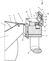
- Fig. 1
- eine perspektivische Schnittansicht eines erfindungsgemäßen Klebebandapplikators,
- Fig. 2
- eine perspektivische Ansicht teilweise als Durchsicht des Klebebandapplikators in
Fig. 1 , - Fig. 3
- eine Untenansicht des Klebebandapplikators in
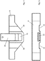
Fig. 1 undFig. 2 , - Fig. 4
- eine Draufsicht einer Umlenkkanteneinheit mit einem Deckel,
- Fig. 5
- eine seitliche Ansicht der Umlenkkanteneinheit ohne den Deckel,
- Fig. 6
- vier Querschnitte eines Dachholms eines Kraftfahrzeuges.
- Die in der
Fig. 1 dargestellte Schnittansicht zeigt den erfindungsgemäßen Klebebandapplikator mit einer Aufnahme 1 für eine Klebebandrolle 2. Die Klebebandrolle 2 ist austauschbar oder nach Verbrauch ersetzbar. Ein freies Ende eines von der Klebebandrolle 2 gelösten Klebebandes 3 wird über eine erste und eine nicht dargestellte zweite Umlenkrolle 4, 6 umgelenkt und einem Applikatorkopf 7 mit einer Umlenkkanteneinheit 8 zugeführt. Die Klebebandrolle 2 weist eine innenseitig der Wickelungen auf das Klebeband aufgebrachte Klebseite auf. - Der Klebebandapplikator umfasst eine Grundeinheit 9 sowie den auf der Grundeinheit 9 austauschbar angeordneten Applikatorkopf 7. Die Grundeinheit 9 umfasst die Aufnahme 1 für die Klebebandrolle 2 mit einem an ihrem freien Ende angeordneten Dorn, auf den die Klebebandrolle 2 aufsteckbar ist sowie einen Klotz 11, an dem die Aufnahme 1 positionsfest befestigt ist. An dem Klotz 11 ist dem Applikatorkopf 7 gegenüberliegend wenigstens ein Griff 12 positionsfest gegenüber dem Klotz 11 angeordnet. Der Griff 12 ist an einer Platte 13 befestigt, die wiederum an dem Klotz 11 befestigt ist. An der Aufnahme 1 sind seitlich dem Klotz 11 gegenüberliegend die beiden Umlenkrollen 4, 6 drehbar angeordnet.
- An der dem Griff 12 gegenüberliegenden Seite ist an dem Klotz 11 der Applikatorkopf 7 lösbar festgeschraubt. An dem Applikatorkopf 7 ist an der der Klebebandrolle 2 abgewandten Seite die Umlenkkanteneinheit 8 vorgesehen. Die Umlenkkanteneinheit 8 ist gegenüber dem Applikatorkopf 7 um einen Winkel α schwenkbar ausgebildet. Die Umlenkkanteneinheit 8 ist um eine Längsachse L schwenkbar am Applikatorkopf 7 angeordnet. Die Längsachse L verläuft in einer Applikationsrichtung A des Klebebandes 3. Die Klebebandrolle 2 weist ebenfalls eine Längsachse auf, die ebenfalls in der Applikationsrichtung A angeordnet ist.
- Die Umlenkkanteneinheit 8 weist eine Applikationsseite 14 auf, die in
Fig. 1 oben auf der Umlenkkanteneinheit 8 angeordnet ist. Entlang der Applikationsseite 14 ist eine Längsnut 16 vorgesehen. In die Längsnut 16 ist ein inFig. 1 nicht dargestelltes Andrückklebeband 17 eingeklebt. Bei dem Andrückklebeband 17 handelt es sich um ein Schaumstoffklebeband, das eine Breite aufweist, die einer Breite B der Längsnut 16 entspricht. Das Andrückklebeband 17 erstreckt sich entlang eines Abschnitts der Längsausdehnung der Längsnut 16 und ist in die Längsnut 16 eingeklebt. Auf eine freie, der Längsnut 16 abgewandte Außenseite des Andrückklebebands 17 kann eine reibungsvermindernde Schicht aufgebracht sein. - Das Klebeband 3 wird um eine gegenüber der Applikationsrichtung A schräge Umlenkkante 18 geführt.
Fig. 2 zeigt in einer Durchsicht der Umlenkkanteneinheit 8 den detaillierten Aufbau der Umlenkkanteneinheit 8. Das inFig. 2 nicht mehr dargestellte Klebeband 3 ist um die erste Umlenkrolle 4 und die in einer Abziehrichtung nachfolgenden zweite Umlenkrolle 6 gemäßFig. 1 geführt. Das Klebeband 3 ist unterhalb der Umlenkkanteneinheit 8 in einer Quernut 19, die in die Umlenkkanteneinheit 8 eingelassen ist, von einer Griffseite zur Umlenkkante 18 des Applikatorkopfes 7 geführt. Die Quernut 19 verläuft senkrecht zur Applikationsrichtung A und senkrecht zur Drehachse der Umlenkkanteneinheit 8. - An der Applikationsseite 14 mündet die Quernut 19 in die schräge Umlenkkante 18. Eine Klebebandführung ist um die Umlenkkante 18 herumgeführt und in der Längsnut 16 auf der Applikationsseite 14 des Applikatorkopfes 7, beziehungsweise der Umlenkkanteneinheit 8, weitergeführt. Die Längsnut 16 verläuft in Applikationsrichtung A.
- Sowohl der Applikatorkopf 7 als auch die Umlenkkanteneinheit 8 sind spiegelsymmetrisch ausgebildet und weisen dafür entsprechende Befestigungsmittel am Klotz 11 auf. Der in
Fig. 2 dargestellte Klebebandapplikator ist für ein Aufbringen des Klebebandes 3 mittels einer manuellen Bewegung in Applikationsrichtung A von rechts nach links ausgebildet. Bei einer Applikationsrichtung A, die von links nach rechts verläuft, müssten die Aufnahme 1 und der Applikatorkopf 7 spiegelbildlich an dem Klotz 11 angeordnet sein. -
Fig. 3 zeigt die Ansicht des Klebebandapplikators von unten. Dabei ist das Klebeband 3 um die zweite Umlenkrolle 6 herumgeführt in die Quernut 19 hineingeführt und von dort um die schräge Umlenkkante 18 herum auf die Applikationsseite 14 der Umlenkkanteneinheit 8 geführt. - Die erfindungsgemäße Umlenkkanteneinheit 8 ist schwenkbar gegenüber und an dem Applikatorkopf 7 ausgebildet. In den Applikatorkopf 7 ist eine Aussparung 22 mit zwei seitlichen Bohrungen 22a, 22b für eine entlang der Längsachse L verlaufende Achse 23 eingebracht. Um die Längsachse L herum ist die Umlenkkanteneinheit 8 schwenkbar angeordnet.
- Auf die Längsachse L ist eine Schenkelfeder 24 gesteckt, die die Umlenkkanteneinheit 8 in einer Neutralstellung gegenüber dem Applikatorkopf 7 hält. In der Neutralstellung weist die Umlenkkanteneinheit 8 einen Winkel α von etwa 20°-90°, vorzugsweise von 40° - 60° gegenüber dem Applikatorkopf 7 auf. Dabei ist der Winkel α zwischen der Applikationsseite 14 der Umlenkkanteneinheit 8 und einer seitlichen Anlageseite 26 des Applikatorkopfes 7 gemessen. Es sind natürlich auch andere Winkel α der Neutralstellung denkbar. Sowohl beim Herausklappen der Umlenkkanteneinheit 8 als auch beim Hineinklappen der Umlenkkanteneinheit 8 jeweils aus der Neutralstellung muss also eine Kraft auf die Umlenkkanteneinheit 8 ausgeübt werden.
- Zur Applikation des Klebebandes 3 wird die Umlenkkanteneinheit 8 manuell mit einem Daumen oder einem Finger in eine etwa senkrechte Stellung gegenüber dem Applikatorkopf 7 ausgeklappt. Dabei ist die Klebebandrolle 2 auf den Dorn der Aufnahme 1 aufgesteckt, und das Klebeband 3 ist über die Umlenkrollen 4, 6 durch die Quernut 19, um die Umlenkkante 18 herum und durch die Längsnut 16 gefädelt.
- Dann wird die Umlenkkanteneinheit 8 des Klebebandapplikator in einen Applikationsspalt eingesteckt und der Klebebandapplikator von rechts nach links entlang des Applikationsspaltes gezogen. Der Applikationsspalt ist dabei beispielsweise der Spalt zwischen einem Dachholm 36 eines Kraftfahrzeuges und der geschlossenen Tür des Kraftfahrzeugs, wobei die Tür noch nicht mit einer Innenverkleidung und Dichtungen versehen ist, so dass der Spalt von einigen Millimetern Breite zwischen der Tür und dem Dachholm 36 ausgebildet wird. In einem Querschnitt weist der Dachholm 36 jedoch beispielsweise zwischen der C-Säule und B-Säule und der B-Säule und A-Säule des Kraftfahrzeugs unterschiedliche Winkel auf, denen sich der erfindungsgemäße Klebebandapplikator jedoch automatisch beim Entlangziehen anpasst, indem der Klebebandapplikator sowohl mit der seitlichen Anlageseite 26 gegen den Dachholm 36 gezogen wird als auch von unten die Umlenkkanteneinheit 8 mit ihrer Applikationsseite 14 gegen den Dachholm 36 gezogen wird.
- Der in der Regel nicht rechtwinkelige, sondern variierend ausgebildete Winkel zwischen der Applikationsseite 14 und der seitlichen Anlageseite 26 wird durch die Schwenkbarkeit der Umlenkkanteneinheit 8 gegenüber dem Applikatorkopf 7 ausgeglichen.
- In die Applikationsseite 14 wie auch in die seitliche Anlageseite 26 ist jeweils wenigstens ein Magnet eingelassen. In die Applikationsseite 14 ist ein applikationsseitiger Magnet 27 und in die seitliche Anlageseite sind ein erster und ein zweiter seitlicher anlageseitiger Magnet 28a, 28b eingelassen. Die Magnete 27, 28a, 28b ziehen die Applikationsseite 14 bzw. die seitliche Anlageseite 26 gegen das Stahlprofil eines Daches 32.
- Die
Fig. 4 zeigt die Umlenkkanteneinheit 8 in einer Draufsicht undFig. 5 in einer seitlichen Ansicht. Die Umlenkkanteneinheit 8 ist im Wesentlichen zweiteilig ausgebildet. Sie weist die eigentliche Umlenkkanteneinheit 8 und einen verschiebbaren Deckel 29 auf. In einen Innenraum 31 der Umlenkkanteneinheit 8 kann der eine Magnet 27 eingeklemmt, eingeklebt oder eingelegt und aus ihm auch leicht wieder herausgenommen werden. Der in den Innenraum 31 hineingelegte Magnet 27 wird durch Schließen des Deckels 29 am Herausfallen gehindert. Der Deckel 29 kann über eine im Deckel 29 vorgesehene Bohrung, durch die eine (nicht dargestellte) Schraube geführt ist, am zufälligen Öffnen gehindert werden. Die in denFig. 4 und 5 dargestellte Umlenkkanteneinheit 8 ist in dem Applikatorkopf 7 um die Achse 23 herum drehbar gelagert. -
Fig. 5 zeigt eine seitliche Ansicht der Umlenkkanteneinheit 8 inFig. 4 . Dabei ist eine T-förmige Nut 30 zu erkennen, in die der mit einer entsprechenden Feder ausgestattete Deckel 29 einschiebbar ist.Fig. 5 zeigt auch die beiden Quernuten 19, entlang denen das Klebeband geführt ist, um dann über die Umlenkkante 18 umgelenkt zu werden. -
Fig. 6 zeigt im unteren Bereich eine seitliche Ansicht einer Fahrzeugseite und des Daches 32 eines Kraftfahrzeuges. In dem oberen Abschnitt derFig. 6 sind Querschnitte an verschiedenen Stellen des Dachholms 36 dargestellt, die mit einem Pfeil gekennzeichnet sind. Der erste Querschnitt ist vor der A-Säule, der zweite und dritte Querschnitt sind zwischen der A- und B-Säule und der dritte Querschnitt ist im Bereich der C-Säule des Kraftfahrzeuges angeordnet. Zu erkennen ist, dass ein Winkel α zwischen einer Innenseite 34, die zur Tür weist, und einer Außenseite 33 des Dachholms 36, die in das Dach 32 übergeht, variabel ist. Im ersten Schnitt vor der A-Säule beträgt der Winkel α zwischen der Innenseite 34 und der Außenseite 33 α > 90°, während er zwischen der A- und B-Säule bei dem Winkel α von etwa 85° - 95° variiert und im Bereich der C-Säule etwa wieder α = 95° annimmt. Da der Klebebandapplikator von außen gegen die Außenseite 33 und von unten gegen die Innenseite 34 des Dachholms 36 gedrückt wird, wird der Winkel α zwischen der Umlenkkanteneinheit 8 und dem Applikatorkopf 7 diesem Winkel zwischen der Außenseite 33 und der Innenseite 34 automatisch beim Entlangführen des Klebebandapplikators entlang des Dachholms 36 angepasst. -
- 1
- Aufnahme
- 2
- Klebebandrolle
- 3
- Klebeband
- 4
- Umlenkrolle
- 6
- Umlenkrolle
- 7
- Applikatorkopf
- 8
- Umlenkkanteneinheit
- 9
- Grundeinheit
- 11
- Klotz
- 12
- Griff
- 13
- Platte
- 14
- Applikationsseite
- 16
- Längsnut
- 17
- Andrückklebeband
- 18
- Umlenkkante
- 19
- Quernut
- 22
- Aussparung
- 22a
- Bohrung
- 22b
- Bohrung
- 23
- Achse
- 24
- Schenkelfeder
- 26
- seitliche Anlageseite
- 27
- Magnet
- 28a
- Magnet
- 28b
- Magnet
- 29
- Deckel
- 30
- T-förmige Nut
- 31
- Innenraum
- 32
- Dach
- 33
- Außenseite
- 34
- Innenseite
- 36
- Dachholm
- A
- Applikationsrichtung
- B
- Breite
- L
- Längsachse
- α
- Winkel
Claims (9)
- Klebebandapplikator mit einer Aufnahme (1) für eine Klebebandrolle (2) und wenigstens einem Griff (12) und einem positionsfest gegenüber dem Griff (12) angeordneten Applikatorkopf (7),
dadurch gekennzeichnet, dass
eine Umlenkkanteneinheit (8) insbesondere beweglich gegenüber dem Applikatorkopf (7) angeordnet ist. - Klebebandapplikator nach Anspruch 1,
dadurch gekennzeichnet, dass die Umlenkkanteneinheit (8) um eine Achse gegenüber dem Applikatorkopf (7) um einen Winkel (α) drehbar angeordnet ist und die Umlenkkanteneinheit (8) mittels einer Feder mit dem Applikatorkopf (7) gekoppelt ist, die die Umlenkkanteneinheit (8) in eine Neutralstellung gegenüber dem Applikatorkopf (7) drückt. - Klebebandapplikator nach Anspruch 1 oder 2,
dadurch gekennzeichnet, dass der Applikatorkopf (7) wenigstens eine quer zu einer Applikationsrichtung (A) verlaufende Quernut (19) für ein Klebeband (3) aufweist und eine in der Applikationsrichtung (A) auf einer Applikationsseite (14) der Umlenkkanteneinheit (8) angeordnete Längsnut (16) aufweist. - Klebebandapplikator nach einem der Ansprüche 1 , 2 oder 3,
dadurch gekennzeichnet, dass in der Längsnut (16) ein Andrückklebeband (17) eingebracht ist. - Klebebandapplikator nach einem der vorstehenden Ansprüche,
dadurch gekennzeichnet, dass die Aufnahme (1) einen in der Applikationsrichtung (A) ausgerichteten Dorn aufweist, auf den die Klebebandrolle (2) steckbar ist, und das Klebeband (3) um wenigstens zwei Umlenkrollen (4, 6) dem Applikatorkopf (7) zuführbar ist. - Klebebandapplikator nach einem der vorstehenden Ansprüche,
dadurch gekennzeichnet, dass der Applikatorkopf (7) eine seitliche Anlageseite (26) aufweist, an der Anlageseite (26) wenigstens ein Magnet (28a, 28b) angeordnet ist und an der Applikationsseite (14) ebenfalls wenigstens ein Magnet (27) angeordnet ist, die die Anlageseite (26) und die Applikationsseite (14) während der Applikation jeweils ständig in Kontakt zu einem Metallprofil halten. - Klebebandapplikator nach einem der vorstehenden Ansprüche,
dadurch gekennzeichnet, dass der Applikatorkopf (7) an einer Grundeinheit (9) austauschbar angeordnet ist und die Grundeinheit (9) den Griff (12) und die Aufnahme (1) umfasst. - Klebebandapplikator nach einem der vorstehenden Ansprüche,
dadurch gekennzeichnet, dass die Umlenkkanteneinheit (8) eine erste und eine zweite zur ersten spiegelbildlich angeordnete Umlenkkante (18) aufweist. - Klebebandapplikator nach einem der vorstehenden Ansprüche,
dadurch gekennzeichnet, dass die Umlenkkanteneinheit (8) einen mit einem Deckel (29) öffnen- und verschließbaren Innenraum (31) für den einen Magneten (27) aufweist.
Applications Claiming Priority (1)
| Application Number | Priority Date | Filing Date | Title |
|---|---|---|---|
| DE102018208845.4A DE102018208845A1 (de) | 2018-06-05 | 2018-06-05 | Klebebandapplikator mit schwenkbarer Umlenkkanteneinheit |
Publications (2)
| Publication Number | Publication Date |
|---|---|
| EP3578490A1 true EP3578490A1 (de) | 2019-12-11 |
| EP3578490B1 EP3578490B1 (de) | 2022-03-23 |
Family
ID=66625780
Family Applications (1)
| Application Number | Title | Priority Date | Filing Date |
|---|---|---|---|
| EP19175369.8A Active EP3578490B1 (de) | 2018-06-05 | 2019-05-20 | Klebebandapplikator mit schwenkbarer umlenkkanteneinheit |
Country Status (7)
| Country | Link |
|---|---|
| US (1) | US11161709B2 (de) |
| EP (1) | EP3578490B1 (de) |
| JP (1) | JP6990211B2 (de) |
| KR (1) | KR102157235B1 (de) |
| CN (1) | CN110562796B (de) |
| DE (1) | DE102018208845A1 (de) |
| ES (1) | ES2918376T3 (de) |
Citations (7)
| Publication number | Priority date | Publication date | Assignee | Title |
|---|---|---|---|---|
| DE4310146C1 (de) * | 1993-03-29 | 1994-06-16 | Daimler Benz Ag | Robotergeführte Vorrichtung zum örtlich gezielten Abkleben von Scheibenflanschen in Fahrzeugkarosserien mit Haftklebeband |
| DE102005034007A1 (de) | 2005-07-18 | 2006-05-18 | Tesa Ag | Handgerät zum Abrollen von einem Klebeband aus einem insbesondere einseitig klebend ausgerüsteten Träger, dessen Klebemasse mit einem Trennmaterial eingedeckt ist |
| DE202007011400U1 (de) | 2007-08-14 | 2008-12-24 | Tesa Ag | Klebeband-Handabroller in Kompaktform |
| US7621309B1 (en) * | 2005-06-30 | 2009-11-24 | Apla-Tech, Inc. | Pneumatic drywall taper |
| US20120055635A1 (en) * | 2009-05-01 | 2012-03-08 | Shinji Inokuchi | Double-faced adhesive tape joining apparatus |
| DE202012004079U1 (de) | 2012-04-25 | 2012-05-09 | Tesa Se | Klebebandhandabroller |
| DE202016008252U1 (de) * | 2016-12-22 | 2017-06-23 | Tesa Se | Klebebandabroller mit Umlenkeinrichtung |
Family Cites Families (29)
| Publication number | Priority date | Publication date | Assignee | Title |
|---|---|---|---|---|
| US4214933A (en) * | 1977-10-25 | 1980-07-29 | Haggar Company | Apparatus for and method of depositing adhesive strips |
| IT1262491B (it) * | 1993-08-02 | 1996-06-28 | Syrom 90 Spa | Procedimento ed attrezzo per lo svolgimento sostanzialmente silenziosodi un nastro autoadesivo dal rotolo erogatore |
| JP2709266B2 (ja) * | 1994-03-01 | 1998-02-04 | ミネソタ マイニング アンド マニュファクチャリング カンパニー | 粘着テープ貼付装置 |
| US5641377A (en) * | 1994-10-26 | 1997-06-24 | Tcc Enterprises | Retractable blade hand held tape applicators |
| JP3012931U (ja) * | 1994-12-26 | 1995-06-27 | 川崎製鉄株式会社 | サンプル鋼板端縁部への粘着テープ貼り機およびその装置 |
| FR2743932B1 (fr) * | 1996-01-18 | 1998-02-13 | Henri Bigot | Outil de gainage d'un faisceau de fils |
| JPH1179127A (ja) * | 1997-07-15 | 1999-03-23 | Nichiban Co Ltd | 簡易結束具 |
| JP3459345B2 (ja) * | 1997-11-17 | 2003-10-20 | リンテック株式会社 | テープ貼付装置 |
| US6796351B1 (en) * | 1997-11-17 | 2004-09-28 | Lintec Corporation | Tape application device |
| US6698489B1 (en) * | 1999-08-06 | 2004-03-02 | Kansai Paint Co., Ltd. | Adhesive tape applicator |
| JP2001123127A (ja) * | 1999-10-26 | 2001-05-08 | Kansai Paint Co Ltd | 粘着性テープ貼付け治具 |
| JP4467172B2 (ja) * | 2000-11-30 | 2010-05-26 | リンテック株式会社 | テープ貼付装置 |
| US6705374B2 (en) * | 2002-03-27 | 2004-03-16 | Hsiu-Man Yu Chen | Adhesive-tape cutting device of an adhesive-tape holder |
| KR100625924B1 (ko) * | 2005-04-08 | 2006-09-20 | 광성기업 주식회사 | 차량용 도어샤시의 테이프 부착장치 |
| JP4731369B2 (ja) * | 2006-03-23 | 2011-07-20 | リンテック株式会社 | テープ貼付装置 |
| US20070267148A1 (en) * | 2006-05-17 | 2007-11-22 | Steele Richard W | Duct Tape Dispenser |
| JP2008007249A (ja) * | 2006-06-28 | 2008-01-17 | Nitto Denko Corp | 粘着テープ貼付け装置 |
| WO2008022027A2 (en) * | 2006-08-10 | 2008-02-21 | 3M Innovative Properties Company | Window sash paint replacement tape application tool and method |
| JP2008184229A (ja) | 2007-01-26 | 2008-08-14 | Mitsubishi Heavy Industries Printing & Paper Converting Machinery Sales Co Ltd | テープ貼り装置およびコルゲートマシン |
| US20100101734A1 (en) * | 2008-10-29 | 2010-04-29 | Yen-Chen Chang | Tape Dispenser |
| KR101046174B1 (ko) * | 2009-11-24 | 2011-07-04 | 주식회사 성우하이텍 | 헤밍용 접착 테이프 공급장치 |
| CN202063594U (zh) * | 2011-05-13 | 2011-12-07 | 天津仁义合自动化技术有限公司 | 胶带自动粘贴装置 |
| JP2014005136A (ja) * | 2012-06-26 | 2014-01-16 | Izumi Toda | 粘着テープ保持切断具 |
| TWI537200B (zh) * | 2013-04-19 | 2016-06-11 | yu-xiong Huang | Trigger tape applicator |
| JP6533067B2 (ja) * | 2015-02-18 | 2019-06-19 | リンテック株式会社 | 接着テープの貼付治具 |
| NL2016572B1 (nl) * | 2016-04-08 | 2017-11-02 | Naber Plastics B V | Inrichting voor het aanbrengen van plakband op een oppervlak en werkwijze voor het vervaardigen van een dergelijke inrichting. |
| US9926165B2 (en) * | 2016-04-25 | 2018-03-27 | Hsiu-Man Yu Chen | Adhesive tape dispenser |
| US11465871B2 (en) * | 2018-01-22 | 2022-10-11 | 3M Innovative Properties Company | Tape dispenser with mount and rotation mechanism |
| US11059279B2 (en) * | 2019-05-07 | 2021-07-13 | Sandar Industries, Inc. | Adhesive tape applicator |
-
2018
- 2018-06-05 DE DE102018208845.4A patent/DE102018208845A1/de not_active Withdrawn
-
2019
- 2019-05-20 EP EP19175369.8A patent/EP3578490B1/de active Active
- 2019-05-20 ES ES19175369T patent/ES2918376T3/es active Active
- 2019-05-31 KR KR1020190064745A patent/KR102157235B1/ko active Active
- 2019-06-03 US US16/430,276 patent/US11161709B2/en active Active
- 2019-06-04 JP JP2019104119A patent/JP6990211B2/ja active Active
- 2019-06-05 CN CN201910484875.6A patent/CN110562796B/zh active Active
Patent Citations (7)
| Publication number | Priority date | Publication date | Assignee | Title |
|---|---|---|---|---|
| DE4310146C1 (de) * | 1993-03-29 | 1994-06-16 | Daimler Benz Ag | Robotergeführte Vorrichtung zum örtlich gezielten Abkleben von Scheibenflanschen in Fahrzeugkarosserien mit Haftklebeband |
| US7621309B1 (en) * | 2005-06-30 | 2009-11-24 | Apla-Tech, Inc. | Pneumatic drywall taper |
| DE102005034007A1 (de) | 2005-07-18 | 2006-05-18 | Tesa Ag | Handgerät zum Abrollen von einem Klebeband aus einem insbesondere einseitig klebend ausgerüsteten Träger, dessen Klebemasse mit einem Trennmaterial eingedeckt ist |
| DE202007011400U1 (de) | 2007-08-14 | 2008-12-24 | Tesa Ag | Klebeband-Handabroller in Kompaktform |
| US20120055635A1 (en) * | 2009-05-01 | 2012-03-08 | Shinji Inokuchi | Double-faced adhesive tape joining apparatus |
| DE202012004079U1 (de) | 2012-04-25 | 2012-05-09 | Tesa Se | Klebebandhandabroller |
| DE202016008252U1 (de) * | 2016-12-22 | 2017-06-23 | Tesa Se | Klebebandabroller mit Umlenkeinrichtung |
Also Published As
| Publication number | Publication date |
|---|---|
| JP6990211B2 (ja) | 2022-01-12 |
| JP2020033183A (ja) | 2020-03-05 |
| KR20190138589A (ko) | 2019-12-13 |
| US11161709B2 (en) | 2021-11-02 |
| DE102018208845A1 (de) | 2019-12-05 |
| US20190367311A1 (en) | 2019-12-05 |
| CN110562796A (zh) | 2019-12-13 |
| KR102157235B1 (ko) | 2020-09-17 |
| CN110562796B (zh) | 2021-09-07 |
| ES2918376T3 (es) | 2022-07-15 |
| EP3578490B1 (de) | 2022-03-23 |
Similar Documents
| Publication | Publication Date | Title |
|---|---|---|
| AT519903B1 (de) | Schiene zur Führung eines Schlittens einer Möbeltüre | |
| EP0868380B1 (de) | Vorrichtung zum aufbringen von klebendem montageband | |
| DE60311828T2 (de) | Abdeckband | |
| DE102015111088A1 (de) | Folienapplikationsgerät, Folienapplikationssystem und Verfahren zur Aufbringung einer Folie auf einer Oberfläche eines Gegenstandes | |
| EP0813910A2 (de) | Schaumstoffstreifen | |
| DE3111748A1 (de) | Geraet zum zusammenfuegen von zwei einseitig mit einer klebeschicht versehenen einfachklebebaendern zu einem doppelklebeband | |
| DE102016226058B4 (de) | Klebebandabroller mit Umlenkeinrichtung | |
| DE102011056056B3 (de) | Tür und Türband | |
| DE4318273C2 (de) | Vorrichtung zur Farbbeschichtung von Profilstangen mit Abdeckschablone | |
| EP3578490B1 (de) | Klebebandapplikator mit schwenkbarer umlenkkanteneinheit | |
| DE60111023T2 (de) | Handgerät zum übertragen eines films auf ein substrat mit einem verdeckbaren auftragelement | |
| DE19933928C2 (de) | Rolladenkasten | |
| DE102008018557A1 (de) | Ablagefach, insbes. in einem Kraftfahrzeug | |
| DE4308135C2 (de) | Nachfüllbarer Spender für Papier- und Folienrollen | |
| DE2216773A1 (de) | Positioniervorrichtung | |
| DE102013010348A1 (de) | Verfahren und Vorrichtung zum Verschließen eines Kartons | |
| DE906291C (de) | Vorrichtung zur Herstellung eines angeklebten Schutzrandes an Blaettern, Umschlaegenund Huellen aus Papier od. dgl. | |
| DE4408901A1 (de) | Verfahren und Vorrichtung zum Behandeln von Zurichtebogen für Bandstahlschnitte | |
| DE19913799C1 (de) | Lackierschablone | |
| DE10135655C2 (de) | Rollladenkasten | |
| DE4025395A1 (de) | Abklebevorrichtung fuer die stirnkanten von moebelplatten | |
| DE1929425A1 (de) | Vorrichtung zur UEbertragung der unregelmaessigen Kontur einer unebenen Flaeche auf einen dieser Flaeche durch Bearbeitung anzupassenden Gegenstand | |
| DE102007005811A1 (de) | Werkzeug zum Applizieren eines Dichtungsprofils | |
| DE4405574C1 (de) | Skikantenschärfer | |
| DE9206183U1 (de) | Musterblattkoffer |
Legal Events
| Date | Code | Title | Description |
|---|---|---|---|
| PUAI | Public reference made under article 153(3) epc to a published international application that has entered the european phase |
Free format text: ORIGINAL CODE: 0009012 |
|
| STAA | Information on the status of an ep patent application or granted ep patent |
Free format text: STATUS: THE APPLICATION HAS BEEN PUBLISHED |
|
| AK | Designated contracting states |
Kind code of ref document: A1 Designated state(s): AL AT BE BG CH CY CZ DE DK EE ES FI FR GB GR HR HU IE IS IT LI LT LU LV MC MK MT NL NO PL PT RO RS SE SI SK SM TR |
|
| AX | Request for extension of the european patent |
Extension state: BA ME |
|
| STAA | Information on the status of an ep patent application or granted ep patent |
Free format text: STATUS: REQUEST FOR EXAMINATION WAS MADE |
|
| 17P | Request for examination filed |
Effective date: 20200612 |
|
| RBV | Designated contracting states (corrected) |
Designated state(s): AL AT BE BG CH CY CZ DE DK EE ES FI FR GB GR HR HU IE IS IT LI LT LU LV MC MK MT NL NO PL PT RO RS SE SI SK SM TR |
|
| GRAP | Despatch of communication of intention to grant a patent |
Free format text: ORIGINAL CODE: EPIDOSNIGR1 |
|
| STAA | Information on the status of an ep patent application or granted ep patent |
Free format text: STATUS: GRANT OF PATENT IS INTENDED |
|
| INTG | Intention to grant announced |
Effective date: 20211028 |
|
| GRAS | Grant fee paid |
Free format text: ORIGINAL CODE: EPIDOSNIGR3 |
|
| GRAA | (expected) grant |
Free format text: ORIGINAL CODE: 0009210 |
|
| STAA | Information on the status of an ep patent application or granted ep patent |
Free format text: STATUS: THE PATENT HAS BEEN GRANTED |
|
| AK | Designated contracting states |
Kind code of ref document: B1 Designated state(s): AL AT BE BG CH CY CZ DE DK EE ES FI FR GB GR HR HU IE IS IT LI LT LU LV MC MK MT NL NO PL PT RO RS SE SI SK SM TR |
|
| REG | Reference to a national code |
Ref country code: GB Ref legal event code: FG4D Free format text: NOT ENGLISH |
|
| REG | Reference to a national code |
Ref country code: CH Ref legal event code: EP |
|
| REG | Reference to a national code |
Ref country code: DE Ref legal event code: R096 Ref document number: 502019003763 Country of ref document: DE |
|
| REG | Reference to a national code |
Ref country code: IE Ref legal event code: FG4D Free format text: LANGUAGE OF EP DOCUMENT: GERMAN |
|
| REG | Reference to a national code |
Ref country code: AT Ref legal event code: REF Ref document number: 1477313 Country of ref document: AT Kind code of ref document: T Effective date: 20220415 |
|
| REG | Reference to a national code |
Ref country code: LT Ref legal event code: MG9D |
|
| REG | Reference to a national code |
Ref country code: ES Ref legal event code: FG2A Ref document number: 2918376 Country of ref document: ES Kind code of ref document: T3 Effective date: 20220715 |
|
| REG | Reference to a national code |
Ref country code: NL Ref legal event code: MP Effective date: 20220323 |
|
| PG25 | Lapsed in a contracting state [announced via postgrant information from national office to epo] |
Ref country code: SE Free format text: LAPSE BECAUSE OF FAILURE TO SUBMIT A TRANSLATION OF THE DESCRIPTION OR TO PAY THE FEE WITHIN THE PRESCRIBED TIME-LIMIT Effective date: 20220323 Ref country code: RS Free format text: LAPSE BECAUSE OF FAILURE TO SUBMIT A TRANSLATION OF THE DESCRIPTION OR TO PAY THE FEE WITHIN THE PRESCRIBED TIME-LIMIT Effective date: 20220323 Ref country code: NO Free format text: LAPSE BECAUSE OF FAILURE TO SUBMIT A TRANSLATION OF THE DESCRIPTION OR TO PAY THE FEE WITHIN THE PRESCRIBED TIME-LIMIT Effective date: 20220623 Ref country code: LT Free format text: LAPSE BECAUSE OF FAILURE TO SUBMIT A TRANSLATION OF THE DESCRIPTION OR TO PAY THE FEE WITHIN THE PRESCRIBED TIME-LIMIT Effective date: 20220323 Ref country code: HR Free format text: LAPSE BECAUSE OF FAILURE TO SUBMIT A TRANSLATION OF THE DESCRIPTION OR TO PAY THE FEE WITHIN THE PRESCRIBED TIME-LIMIT Effective date: 20220323 Ref country code: BG Free format text: LAPSE BECAUSE OF FAILURE TO SUBMIT A TRANSLATION OF THE DESCRIPTION OR TO PAY THE FEE WITHIN THE PRESCRIBED TIME-LIMIT Effective date: 20220623 |
|
| PG25 | Lapsed in a contracting state [announced via postgrant information from national office to epo] |
Ref country code: LV Free format text: LAPSE BECAUSE OF FAILURE TO SUBMIT A TRANSLATION OF THE DESCRIPTION OR TO PAY THE FEE WITHIN THE PRESCRIBED TIME-LIMIT Effective date: 20220323 Ref country code: GR Free format text: LAPSE BECAUSE OF FAILURE TO SUBMIT A TRANSLATION OF THE DESCRIPTION OR TO PAY THE FEE WITHIN THE PRESCRIBED TIME-LIMIT Effective date: 20220624 Ref country code: FI Free format text: LAPSE BECAUSE OF FAILURE TO SUBMIT A TRANSLATION OF THE DESCRIPTION OR TO PAY THE FEE WITHIN THE PRESCRIBED TIME-LIMIT Effective date: 20220323 |
|
| PG25 | Lapsed in a contracting state [announced via postgrant information from national office to epo] |
Ref country code: NL Free format text: LAPSE BECAUSE OF FAILURE TO SUBMIT A TRANSLATION OF THE DESCRIPTION OR TO PAY THE FEE WITHIN THE PRESCRIBED TIME-LIMIT Effective date: 20220323 |
|
| PG25 | Lapsed in a contracting state [announced via postgrant information from national office to epo] |
Ref country code: SM Free format text: LAPSE BECAUSE OF FAILURE TO SUBMIT A TRANSLATION OF THE DESCRIPTION OR TO PAY THE FEE WITHIN THE PRESCRIBED TIME-LIMIT Effective date: 20220323 Ref country code: SK Free format text: LAPSE BECAUSE OF FAILURE TO SUBMIT A TRANSLATION OF THE DESCRIPTION OR TO PAY THE FEE WITHIN THE PRESCRIBED TIME-LIMIT Effective date: 20220323 Ref country code: RO Free format text: LAPSE BECAUSE OF FAILURE TO SUBMIT A TRANSLATION OF THE DESCRIPTION OR TO PAY THE FEE WITHIN THE PRESCRIBED TIME-LIMIT Effective date: 20220323 Ref country code: PT Free format text: LAPSE BECAUSE OF FAILURE TO SUBMIT A TRANSLATION OF THE DESCRIPTION OR TO PAY THE FEE WITHIN THE PRESCRIBED TIME-LIMIT Effective date: 20220725 Ref country code: EE Free format text: LAPSE BECAUSE OF FAILURE TO SUBMIT A TRANSLATION OF THE DESCRIPTION OR TO PAY THE FEE WITHIN THE PRESCRIBED TIME-LIMIT Effective date: 20220323 Ref country code: CZ Free format text: LAPSE BECAUSE OF FAILURE TO SUBMIT A TRANSLATION OF THE DESCRIPTION OR TO PAY THE FEE WITHIN THE PRESCRIBED TIME-LIMIT Effective date: 20220323 |
|
| PG25 | Lapsed in a contracting state [announced via postgrant information from national office to epo] |
Ref country code: PL Free format text: LAPSE BECAUSE OF FAILURE TO SUBMIT A TRANSLATION OF THE DESCRIPTION OR TO PAY THE FEE WITHIN THE PRESCRIBED TIME-LIMIT Effective date: 20220323 Ref country code: IS Free format text: LAPSE BECAUSE OF FAILURE TO SUBMIT A TRANSLATION OF THE DESCRIPTION OR TO PAY THE FEE WITHIN THE PRESCRIBED TIME-LIMIT Effective date: 20220723 Ref country code: AL Free format text: LAPSE BECAUSE OF FAILURE TO SUBMIT A TRANSLATION OF THE DESCRIPTION OR TO PAY THE FEE WITHIN THE PRESCRIBED TIME-LIMIT Effective date: 20220323 |
|
| REG | Reference to a national code |
Ref country code: CH Ref legal event code: PL |
|
| REG | Reference to a national code |
Ref country code: DE Ref legal event code: R097 Ref document number: 502019003763 Country of ref document: DE |
|
| REG | Reference to a national code |
Ref country code: BE Ref legal event code: MM Effective date: 20220531 |
|
| PLBE | No opposition filed within time limit |
Free format text: ORIGINAL CODE: 0009261 |
|
| STAA | Information on the status of an ep patent application or granted ep patent |
Free format text: STATUS: NO OPPOSITION FILED WITHIN TIME LIMIT |
|
| PG25 | Lapsed in a contracting state [announced via postgrant information from national office to epo] |
Ref country code: MC Free format text: LAPSE BECAUSE OF FAILURE TO SUBMIT A TRANSLATION OF THE DESCRIPTION OR TO PAY THE FEE WITHIN THE PRESCRIBED TIME-LIMIT Effective date: 20220323 Ref country code: LU Free format text: LAPSE BECAUSE OF NON-PAYMENT OF DUE FEES Effective date: 20220520 Ref country code: LI Free format text: LAPSE BECAUSE OF NON-PAYMENT OF DUE FEES Effective date: 20220531 Ref country code: DK Free format text: LAPSE BECAUSE OF FAILURE TO SUBMIT A TRANSLATION OF THE DESCRIPTION OR TO PAY THE FEE WITHIN THE PRESCRIBED TIME-LIMIT Effective date: 20220323 Ref country code: CH Free format text: LAPSE BECAUSE OF NON-PAYMENT OF DUE FEES Effective date: 20220531 |
|
| 26N | No opposition filed |
Effective date: 20230102 |
|
| PG25 | Lapsed in a contracting state [announced via postgrant information from national office to epo] |
Ref country code: IE Free format text: LAPSE BECAUSE OF NON-PAYMENT OF DUE FEES Effective date: 20220520 |
|
| PG25 | Lapsed in a contracting state [announced via postgrant information from national office to epo] |
Ref country code: SI Free format text: LAPSE BECAUSE OF FAILURE TO SUBMIT A TRANSLATION OF THE DESCRIPTION OR TO PAY THE FEE WITHIN THE PRESCRIBED TIME-LIMIT Effective date: 20220323 Ref country code: BE Free format text: LAPSE BECAUSE OF NON-PAYMENT OF DUE FEES Effective date: 20220531 |
|
| PG25 | Lapsed in a contracting state [announced via postgrant information from national office to epo] |
Ref country code: IT Free format text: LAPSE BECAUSE OF FAILURE TO SUBMIT A TRANSLATION OF THE DESCRIPTION OR TO PAY THE FEE WITHIN THE PRESCRIBED TIME-LIMIT Effective date: 20220323 |
|
| PG25 | Lapsed in a contracting state [announced via postgrant information from national office to epo] |
Ref country code: MK Free format text: LAPSE BECAUSE OF FAILURE TO SUBMIT A TRANSLATION OF THE DESCRIPTION OR TO PAY THE FEE WITHIN THE PRESCRIBED TIME-LIMIT Effective date: 20220323 Ref country code: CY Free format text: LAPSE BECAUSE OF FAILURE TO SUBMIT A TRANSLATION OF THE DESCRIPTION OR TO PAY THE FEE WITHIN THE PRESCRIBED TIME-LIMIT Effective date: 20220323 |
|
| PG25 | Lapsed in a contracting state [announced via postgrant information from national office to epo] |
Ref country code: HU Free format text: LAPSE BECAUSE OF FAILURE TO SUBMIT A TRANSLATION OF THE DESCRIPTION OR TO PAY THE FEE WITHIN THE PRESCRIBED TIME-LIMIT; INVALID AB INITIO Effective date: 20190520 |
|
| PG25 | Lapsed in a contracting state [announced via postgrant information from national office to epo] |
Ref country code: TR Free format text: LAPSE BECAUSE OF FAILURE TO SUBMIT A TRANSLATION OF THE DESCRIPTION OR TO PAY THE FEE WITHIN THE PRESCRIBED TIME-LIMIT Effective date: 20220323 |
|
| PG25 | Lapsed in a contracting state [announced via postgrant information from national office to epo] |
Ref country code: MT Free format text: LAPSE BECAUSE OF FAILURE TO SUBMIT A TRANSLATION OF THE DESCRIPTION OR TO PAY THE FEE WITHIN THE PRESCRIBED TIME-LIMIT Effective date: 20220323 |
|
| PGFP | Annual fee paid to national office [announced via postgrant information from national office to epo] |
Ref country code: DE Payment date: 20250521 Year of fee payment: 7 |
|
| PGFP | Annual fee paid to national office [announced via postgrant information from national office to epo] |
Ref country code: GB Payment date: 20250527 Year of fee payment: 7 |
|
| REG | Reference to a national code |
Ref country code: AT Ref legal event code: MM01 Ref document number: 1477313 Country of ref document: AT Kind code of ref document: T Effective date: 20240520 |
|
| PGFP | Annual fee paid to national office [announced via postgrant information from national office to epo] |
Ref country code: FR Payment date: 20250528 Year of fee payment: 7 |
|
| PG25 | Lapsed in a contracting state [announced via postgrant information from national office to epo] |
Ref country code: AT Free format text: LAPSE BECAUSE OF NON-PAYMENT OF DUE FEES Effective date: 20240520 |
|
| PGFP | Annual fee paid to national office [announced via postgrant information from national office to epo] |
Ref country code: ES Payment date: 20250630 Year of fee payment: 7 |
|
| PGFP | Annual fee paid to national office [announced via postgrant information from national office to epo] |
Ref country code: AT Payment date: 20260410 Year of fee payment: 5 |