EP3578518B1 - Capteur pour évaluer la composition ionique d'une solution, un adoucisseur d'eau connecté au capteur et une méthode pour détecter le changement de composition ionique à l'aide du capteur - Google Patents
Capteur pour évaluer la composition ionique d'une solution, un adoucisseur d'eau connecté au capteur et une méthode pour détecter le changement de composition ionique à l'aide du capteur Download PDFInfo
- Publication number
- EP3578518B1 EP3578518B1 EP19189569.7A EP19189569A EP3578518B1 EP 3578518 B1 EP3578518 B1 EP 3578518B1 EP 19189569 A EP19189569 A EP 19189569A EP 3578518 B1 EP3578518 B1 EP 3578518B1
- Authority
- EP
- European Patent Office
- Prior art keywords
- sensor
- ion
- fluid
- cavity
- exchange
- Prior art date
- Legal status (The legal status is an assumption and is not a legal conclusion. Google has not performed a legal analysis and makes no representation as to the accuracy of the status listed.)
- Active
Links
Images




Classifications
-
- G—PHYSICS
- G01—MEASURING; TESTING
- G01R—MEASURING ELECTRIC VARIABLES; MEASURING MAGNETIC VARIABLES
- G01R27/00—Arrangements for measuring resistance, reactance, impedance, or electric characteristics derived therefrom
- G01R27/02—Measuring real or complex resistance, reactance, impedance, or other two-pole characteristics derived therefrom, e.g. time constant
- G01R27/22—Measuring resistance of fluids
-
- B—PERFORMING OPERATIONS; TRANSPORTING
- B01—PHYSICAL OR CHEMICAL PROCESSES OR APPARATUS IN GENERAL
- B01J—CHEMICAL OR PHYSICAL PROCESSES, e.g. CATALYSIS OR COLLOID CHEMISTRY; THEIR RELEVANT APPARATUS
- B01J49/00—Regeneration or reactivation of ion-exchangers; Apparatus therefor
- B01J49/80—Automatic regeneration
- B01J49/85—Controlling or regulating devices therefor
-
- C—CHEMISTRY; METALLURGY
- C02—TREATMENT OF WATER, WASTE WATER, SEWAGE, OR SLUDGE
- C02F—TREATMENT OF WATER, WASTE WATER, SEWAGE, OR SLUDGE
- C02F1/00—Treatment of water, waste water, or sewage
- C02F1/008—Control or steering systems not provided for elsewhere in subclass C02F
-
- C—CHEMISTRY; METALLURGY
- C02—TREATMENT OF WATER, WASTE WATER, SEWAGE, OR SLUDGE
- C02F—TREATMENT OF WATER, WASTE WATER, SEWAGE, OR SLUDGE
- C02F1/00—Treatment of water, waste water, or sewage
- C02F1/42—Treatment of water, waste water, or sewage by ion-exchange
-
- G—PHYSICS
- G01—MEASURING; TESTING
- G01N—INVESTIGATING OR ANALYSING MATERIALS BY DETERMINING THEIR CHEMICAL OR PHYSICAL PROPERTIES
- G01N27/00—Investigating or analysing materials by the use of electric, electrochemical, or magnetic means
- G01N27/02—Investigating or analysing materials by the use of electric, electrochemical, or magnetic means by investigating impedance
- G01N27/04—Investigating or analysing materials by the use of electric, electrochemical, or magnetic means by investigating impedance by investigating resistance
- G01N27/12—Investigating or analysing materials by the use of electric, electrochemical, or magnetic means by investigating impedance by investigating resistance of a solid body in dependence upon absorption of a fluid; of a solid body in dependence upon reaction with a fluid, for detecting components in the fluid
-
- G—PHYSICS
- G01—MEASURING; TESTING
- G01N—INVESTIGATING OR ANALYSING MATERIALS BY DETERMINING THEIR CHEMICAL OR PHYSICAL PROPERTIES
- G01N33/00—Investigating or analysing materials by specific methods not covered by groups G01N1/00 - G01N31/00
- G01N33/18—Water
- G01N33/1853—Hardness of water
-
- C—CHEMISTRY; METALLURGY
- C02—TREATMENT OF WATER, WASTE WATER, SEWAGE, OR SLUDGE
- C02F—TREATMENT OF WATER, WASTE WATER, SEWAGE, OR SLUDGE
- C02F2209/00—Controlling or monitoring parameters in water treatment
- C02F2209/05—Conductivity or salinity
- C02F2209/055—Hardness
-
- C—CHEMISTRY; METALLURGY
- C02—TREATMENT OF WATER, WASTE WATER, SEWAGE, OR SLUDGE
- C02F—TREATMENT OF WATER, WASTE WATER, SEWAGE, OR SLUDGE
- C02F2303/00—Specific treatment goals
- C02F2303/16—Regeneration of sorbents, filters
Definitions
- This invention relates to a sensor for assessing the ionic composition of a solution, a water softening system comprising a water softener apparatus connected to such sensor and a method for detecting the change in an ionic composition of a fluid using such a sensor.
- Some water softeners are configured to pass hard water through an ion exchange resin or mineral bed to remove hardness ions from the water.
- the ion exchange resin or mineral to a limited extent, also removes dissolved iron through an ion exchange process.
- the ion exchange resin or mineral bed is recharged to regenerate its hardness and iron removal capability by passing brine through the resin or mineral bed and by backwashing.
- the ion-exchange resin or mineral bed is typically regenerated with a brine of NaCl when its ion-exchange capacity is exhausted.
- An important aspect of the control of a water softener is the determination of when to initiate the regeneration. For most efficient utilization of salt for regenerating and water for rinsing, it is advantageous to initiate regeneration as soon as breakthrough is detected, but existing analytical instruments for measuring hardness in the water are notoriously expensive and time-consuming.
- the alternative to detecting breakthrough is to make a conservative estimate of when resin exhaustion will occur with calculations based on assumptions of the hardness of the feed water and the quantity of water that has passed through the resin bed. In one approach total daily water usage is estimated and a timer initiates regeneration after the lapse of a certain number of days.
- the timer does not distinguish days when there is no flow of water from days when there is a high flow, and the softener might be regenerated when little or none of its capacity has been utilized or it might be regenerated long after breakthrough has occurred, resulting in the passage of untreated hard water.
- Another approach is to use a flow totalizer, which measures the quantity of water that has been processed by the softener and initiates regeneration when a preselected quantity of water has been processed.
- Use of the flow totalizer usually results in better salt economy than the timer, but that approach does not account for variation in the hardness of the source water or deterioration in the ion-exchange capacity as the resin ages.
- the electrical conductivity of the resin bed is used to determine the need for regeneration. Utilization of the conductivity measurement is based on the fact that calcium ions are more tightly held by the resin, and consequently the resin is less conductive in the calcium form than in the sodium form.
- the measurement of resin bed conductivity is confounded by two problems. First, the continuity of current flow between resin beads is through point contacts between spheres, so the measured conductivity through the path of resin beads is much lower than the conductivity of the individual beads. Second, the solution between the beads is also conductive, so changes in the conductivity of the solution will affect the measured conductivity by providing a shunt through which electric current flows.
- a common approach to alleviating these problems is to install multiple pairs of electrodes in the resin bed and compare the measurements. These embedded probes still suffer from the fact that they rely on an indirect measurement and do not directly detect breakthrough of calcium.
- EP 0 605 714 A1 discloses a sensor capable of assessing the ionic composition of a solution known from the prior art.
- US 2003/056646 A1 discloses a gas removal filter with an ion exchanger for adsorbing a gas and at least a pair of electric resistance measuring electrodes disposed on the ion exchanger.
- the present invention is as defined in the claims. Any examples which do not fall within the claims are provided as illustrative examples. Disclosed herein are an apparatus, devices, and/or methods for assessing the ionic composition of a solution by measuring the ionic conductivity of an ion-exchange material that is or has been in contact with an electrolyte solution.
- the ion-exchange material is a continuous material that is in the form of a fiber bundle.
- the ion-exchange material can be a membrane, fiber, or the like that is positioned between two electrodes.
- the apparatus, devices, and methods described herein use a continuous ion-exchange material in the sensor to overcome the inaccuracies associated with particle-to-particle contact and the shunt effect of the conductive solution between the particles.
- the solution can be an electrolyte solution.
- the electrolyte solution can be water.
- the water can be water that has been treated or is being treated using a water softener device or method.
- Information about the ionic composition of the water treated by a water softener can be used as the basis for control schemes to accurately direct regeneration of a softening column or material when and as needed.
- a device or method described herein can provide for minimizing the amount of salt and water used for regeneration, thus reducing the amount of spent brine needing disposal or treatment. With a sensor system of the present invention, regeneration is carried out only as needed, resulting in a lower burden on the waste treatment system and a reduced discharge of salt into the environment.
- a sensor apparatus for measuring conductivity comprising a continuous ion-exchange material and a voltage divider where the ion-exchange material serves as one leg of the voltage divider in order to generate a voltage that is proportional to the conductivity of the ion-exchange material.
- the ion-exchange material can be a polymer, paper, or plastic that has been modified with ion-exchange groups.
- the other leg of the voltage divider can be a resistor.
- the resistor can be a thermistor.
- a thermistor is a type of resistor whose resistance varies significantly with temperature, more so than in standard resistors.
- Thermistors are widely used as inrush current limiter, temperature sensors (NTC type typically), self-resetting overcurrent protectors, and self-regulating heating elements.
- Thermistors differ from resistance temperature detectors (RTDs) in that the material used in a thermistor is generally a ceramic or polymer, while RTDs use pure metals. The temperature response is also different; RTDs are useful over larger temperature ranges, while thermistors typically achieve a higher precision within a limited temperature range, typically -90 °C to 130 °C.
- a sensor for measuring conductivity comprising (i) a continuous ion-exchange material, and (ii) a voltage divider wherein the ion-exchange material serves as one leg of a voltage divider in order to generate a voltage that is proportional to the conductivity.
- the leg of the voltage divider can be a resistor, e.g., a thermistor.
- Switches can be engaged periodically in a manner to cause said electrical current to flow in either of two directions in said sensor or to remove electrical current flow from said sensor.
- the voltage can be latched so as to store a value that is proportional to said conductivity.
- a sensor for detecting a change in ionic composition of a fluid comprising (i) a first non-conductive plate and a second non-conductive plate configured to form a cavity through which a test fluid flows, (ii) a continuous ion-exchange material positioned within the cavity and in contact with the fluid, (iii) a first electrode in contact with a first portion of the ion-exchange material and a second electrode in contact with a second portion of the ion-exchange material, the first and second electrode being separated by a predetermined distance, and (iv) a device coupled to the ion-exchange material configured for measuring the electrical conductivity across the ion-exchange material.
- the continuous ion-exchange material can be a membrane or fiber.
- the ion-exchange membrane can be a cation-exchange or an anion-exchange membrane.
- the non-conductive plates can be planar or semicircular.
- the sensor may further comprise a diaphragm positioned in the cavity between a non-conductive plate and the ion exchange material, said diaphragm being configured, upon application of pressure to the diaphragm, to displace fluid between the diaphragm and the ion-exchange material for the purpose of eliminating the fluid as an alternative path for the flow of electric current between the electrodes.
- the diaphragm can be coupled to an actuator.
- the actuator can be an electrical, hydraulic, pneumatic, or mechanical actuator. The actuator can move the diaphragm to evacuate the sensor cavity. The cavity can be opened after a period of time and fluid flows through cavity until the actuator is engaged.
- a water softener system comprising a water softener apparatus fluidically connected to one or more sensors described herein.
- a sensor is positioned such that a portion of fluid exiting the water softener flows through the sensor.
- the sensor can be positioned such that a portion of fluid flowing through the water softener flows through the sensor during transit through softener.
- a water hardness sensor that can comprise (i) a first non-conductive plate and a second non-conductive plate configured to form a cavity through which a test fluid flows, wherein a surface of at least one of the plates facing the cavity is chemically modified to form an ion-exchange surface, (ii) a first electrode in contact with a first portion of the ion-exchange surface and a second electrode in contact with a second portion of the ion-exchange surface, the first and second electrode being separated by a predetermined distance, and (iii) a device for measuring the electrical conductivity across the ion-exchange surface operatively coupled to the first and second electrodes.
- a water hardness sensor that can comprise (i) a non-conductive block that forms the housing for the sensor, said block forming a cavity; (ii) two or more ion-exchange fibers forming a fiber bundle are positioned in the cavity, wherein one end of the fiber bundle is in electrical contact with a first electrode and the other end is in electrical contact with a second electrode, the first and second electrode being separated by a predetermined distance, and (iii) and the first and second electrodes connected to a device for measuring the electrical conductivity across the ion-exchange fibers.
- a method for detecting a change in ionic composition of a fluid can comprise (i) contacting a sensor with a first fluid sample at a first time point, wherein the sensor comprises a continuous ion-exchange material and a resistor in electrical series where voltage across the ion-exchange material is proportional to the electrical conductivity of the ion-exchange material and detecting the voltage across the ion-exchange material at the first time point; (ii) contacting the sensor with a second fluid sample at a second time point and detecting the voltage across the ion-exchange material at the second time point; and (iii) determining the change in ionic composition of the fluid based on the change in voltage across the ion-exchange material.
- the method can further comprise evacuating the fluid sample from the sensor cavity after a predetermined period of time prior to detecting the voltage across the ion-exchange material.
- Water softeners can comprise cation-exchange resins that have the ability to take up cations like sodium, potassium, calcium, and magnesium.
- Typical cation-exchange resins useful in water softeners are prepared by suspension polymerization of monomer styrene and the crosslinking agent divinylbenzene to form polymer beads.
- the polymer beads are subsequently treated with a sulfonating agent, attaching sulfonic acid groups to the polymer.
- the sulfonic acid groups impart a negative ionic charge to the cation-exchange beads.
- When the beads are exposed to a salt solution that negative charge becomes associated with cations in solution.
- the cations in the beads are sodium ions.
- Water is said to be "hard” if it has a high concentration (>24 mg/L Ca) of dissolved minerals that are prone to precipitation and producing scale on pipes and fixtures.
- This scale may be cosmetically objectionable when it is deposited in toilets or sinks. Scale can also cause a reduction in diameter in pipes and can hinder heat transfer of heat exchangers by impeding convection and adding to conductive thermal resistance.
- dissolved minerals can be removed using cation-exchange resins softening the water. In dilute aqueous solutions, cation-exchange resins of the sulfonated styrene-divinylbenzene type have a strong affinity for calcium and magnesium ions, which are major contributors to water hardness.
- the ion-exchange capacity of a resin can be regenerated by exposing the resin to a concentrated solution of sodium chloride (i.e., brine).
- the sodium ions in the brine displace the hardness ions in the resin, and the ion-exchange capacity of the resin is regenerated.
- a typical water softener apparatus comprise of cation-exchange beads contained in a cylindrical tank. Hard water is allowed to flow downward through the bed of resin beads and calcium ions are removed as the water comes into contact with the beads. The beads at the top of the resin bed become exhausted first, and then the exhaustion proceeds down the bed until the flow is stopped or until the resin is fully exhausted. When the resin bed gets exhausted the condition of breakthrough occurs, and calcium ions appear in increasingly higher concentrations in the treated water.
- Regeneration can be done by introducing a concentrated solution of sodium chloride, or brine, from the bottom of the resin bed, a process known as counter-current regeneration. As the brine moves slowly up through the bed, calcium ions are displaced and carried out with the brine.
- the brine solution produced by regeneration is called spent brine and typically has a high concentration of calcium chloride at the beginning of the regeneration cycle. The calcium ion concentration decreases as regeneration progresses.
- the spent brine can contain other displaced ions, in addition to sodium and calcium, such as magnesium. Because the resin in the bottom of the bed is being exposed to pure sodium chloride solution, the resin in the bottom of the bed becomes fully regenerated. In some cases the resin in the top of the bed might be only partially regenerated.
- the slow rinse is followed by a fast rinse to wash out any remaining sodium chloride from the resin bed.
- the fast rinse is typically at a higher flow rate, e.g., 133 to 200 liter per cubic meter per minute (1 to 1.5 gpm per cubic foot).
- a control system governs the operations mentioned.
- the control system usually sits on top of the cylindrical tank containing the resin.
- the control system comprises a controller, valves, motors, gears, timers, switches, meters, and circuitry needed to control the sequencing of the operating cycles.
- the measurements can be used to determine control actions.
- the ion-exchange material might be in contact with the processed water coming out of the water softener. When breakthrough occurs, the processed water will begin having a higher concentration of calcium ions, and this will affect the ionic conductivity of the ion-exchange material of the sensor. In some settings, an absolute decrease of ionic conductivity above a preset threshold will be indicative of a resin bed that is becoming exhausted.
- sensor inputs available for making decisions as to the initiation of regeneration. These could include multiple ionic conductivity measurements from sensors. These could also include a measurement of flow rate and measurements of one or more of ambient temperature, resin bed temperature, or fluid stream temperature.
- sensor data can be collected over time and then processed in batch to determine a control action. For example, if the ionic conductivity measured by a sensor is changing quickly, that may be indicative of a rapidly exhausting resin bed. In contrast, a slowly changing ionic conductivity, particularly if it correlates with temperature change, may simply be a reflection of aging and/or temperature dependence of the measured conductivity.
- FIG. 1 shows a planar sensor 10 containing an ion-exchange material in the form of membrane 11 with its edges in contact with a pair of electrodes 12 and 13 separated by a prescribed distance.
- the membrane 11 is exposed to a cavity 14 through which the solution flows across the membrane, that is, either into or out of the page in FIG. 1 .
- Electrodes 12 and 13 are in electrical contact with the membrane 11.
- a gasket 15 of resilient material serves to press the membrane tightly against the electrodes to ensure the electrical contact.
- End plates 16 and 17 can be made of non-conductive material and provide the structure for the sensor.
- FIG. 1 shows the simplest arrangement of the components of planar sensor 10.
- the fluid flowing through cavity 14 is in contact with the membrane 11, and the ions in the fluid exchange with the ions in membrane 11 until a condition of equilibrium is approached.
- the fluid would be water containing mostly sodium and calcium ions.
- Membrane 11 of the sensor would be in contact with water from the discharge of the softener that flows through cavity 14.
- sodium ions are the dominant cations in the water, and consequently sodium ions are the dominant cations in membrane 11.
- membrane 11 is in its most conductive state.
- the conductivity of membrane 11 is measured by means similar to those used for measuring solution conductivity. An alternating current of high frequency and low amperage can be used to minimize polarization at the contacts between membrane 11 and electrodes 12 and 13. Measurement of a substantially steady value of membrane electrical conductivity is an indication that the resin bed still has useful softening capacity.
- the ion-exchange material is illustrated as a membrane sheet in FIG. 1 , but the invention includes ion-exchange materials in the form of a bundle of two or more ion-exchange fibers. In certain embodiments the fibers are in electrical contact with the electrodes.
- the ion-exchange material can also be an integral part of one or both of end plates 16 and 17.
- the invention can include an integral ion-exchange material that is attached to the surface of an end plate by means that include adhesion, fusion, polymerization of monomers on or within the material of the end plate, or functionalization of the polymer of the end plate to form ion-exchange groups on the surface of the plate.
- An end plate made of poly (vinyl chloride) (PVC) can be exposed to the monomers styrene and divinylbenzene, which are absorbed into the surface of the PVC plate.
- the surface of the plate is exposed to a polymerization initiator such as benzoyl peroxide, irradiation, or any other known polymerization initiator or catalyst.
- a polymerization initiator such as benzoyl peroxide, irradiation, or any other known polymerization initiator or catalyst.
- the polymer coating is treated with a reagent that produces ion-exchange groups on the polymer.
- Sulfuric acid is an example of a treatment agent to produce cation-exchange groups on the styrene/divinylbenzene copolymer.
- the surface of the plate may include a polymer that is made from monomers that include styrene.
- styrene-containing polymers examples include poly(acrylonitrile- co butadiene- co -styrene) (ABS), poly(styrene-isobutylene-styrene) triblock copolymers (SIBS), and styrene butadiene rubber (SBR).
- ABS poly(acrylonitrile- co butadiene- co -styrene)
- SIBS poly(styrene-isobutylene-styrene) triblock copolymers
- SBR styrene butadiene rubber
- the styrene-containing polymer is treated with a sulfonating agent, e.g. sulfuric acid, to impart cation-exchange properties to the surface of the polymer.
- a sulfonating agent e.g. sulfuric acid
- the thickness of the layer of ion-exchange material can be minimized in order to minimize the distance that ions must diffuse into the surface of the polymer. Reducing the diffusion distance beneficially reduces the response time of the hardness sensor.
- FIG. 2 shows a planar sensor in which the end plates 26 and 27 contain multiple slots 28 through which the solution flows.
- the slots are separated by ridges 29 that are close to or touching membrane 21.
- the ridges serve to interrupt the flow of electric current through the solution between electrodes 22 and 23 by interrupting the fluid path between adjoining slots and thereby reducing the conductivity path between electrodes and through the solution.
- Ridges 29 can be formed by cutting or molding slots 28 into the end plates or by inserting non-conductive netting with parallel strands, such as the netting supplied by Conwed. Ridges 29 and slots 28 can be on both sides of membrane 21 as shown in FIG. 2 , or they can be on only one side of the membrane.
- a benefit of having ridges 29 and slots 28 on both sides of membrane 21 is that solution can flow on both sides of the membrane 21 and cause faster equilibration of the ion exchange sites in membrane 21. It should be noted that slots 28 serve the function of conveyance of the solution through the sensor to contact the membrane, which is the same function as cavity 14 in FIG. 1 .
- FIG. 3 illustrates a sensor with diaphragm 30 that can be actuated to displace the solution that is in cavity 34 through which the solution flows to contact membrane 31.
- the device can be configured for actuating the diaphragm.
- the diaphragm can be actuated using hydraulic pressure, pneumatic pressure, mechanical force or the like, or any means known in the art, for displacing a diaphragm.
- Activating a diaphragm is just one way of displacing the solution in contact with the membrane. The intent is to remove the solution from the path of measurement of the conductivity of the membrane so that a change in the conductivity of the solution does not impact the measurement. Any means for displacing the solution during the measurement of electrical conductivity is included in the invention.
- a piston actuated directly or indirectly by a solenoid is means of displacing the solution.
- a preferred means of actuating diaphragm 30 is to restrict the flow of solution into cavity 34 and divert the solution to the backside of the diaphragm in order to achieve a higher pressure on the backside of the diaphragm than in the cavity.
- solution flows through cavity 34 to allow exchange of ions between membrane 31 and the solution to be tested.
- diaphragm 30 is actuated so that it is pressed against membrane 31 to displace the solution from cavity 34.
- the membrane conductivity is measured.
- the actuation of diaphragm 30 is reversed, and solution is allowed to flow through cavity 34.
- the ion-conductive function of membrane 31 can be replaced by imparting ion-exchange properties to the surface of the end plate 37.
- the diaphragm allows the sensor to serve two functions. If the sensor is situated in or connected to the line that conveys solution exiting the resin bed, the sensor is exposed to the treated water during the service cycle of the softener, and it is exposed to the brine and rinse solutions during the regeneration cycle. With a large volume in the cavity, the membrane contributes negligible conductivity of the sensor when the cavity is filled, so the sensor measures the conductivity of the solution. But when the volume of the cavity is displaced by the diaphragm, the conductivity of the membrane is dominant, and the sensor measures the conductivity of the membrane, which reflects the composition of the solution that has been in contact with the membrane.
- This dual-function sensor is useful in the operation of the water softener, because it can be used to detect when a water softener needs to be regenerated, and it can detect when the brine has been adequately rinsed from the regenerated resin.
- the benefit of the latter detection is that the flow of rinse water can be stopped as soon as adequate rinsing has been detected rather than after a programmed time of rinsing.
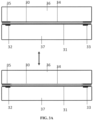
- FIG. 4 illustrates a sensor in a tubular configuration with a semicircular diaphragm 40 that can be actuated to displace the solution that is in cavity 44 through which the solution flows to contact semicircular membrane 41.
- the device may include an actuator for diaphragm 40.
- the actuator can act on diaphragm 40 by use of hydraulic pressure, pneumatic pressure, a mechanical force or any other means know in the art for displacing a diaphragm.
- Electrodes 42 and 43 can be positioned on opposite sides of the tube and attached to the surface of membrane 41 at its edge. When diaphragm 40 is not actuated, as shown on the left view of FIG.
- the cavity is wide open and ions in the fluid flowing through the cavity equilibrate with ions in membrane 41. Also, since the fluid occupies most of the volume between electrodes 42 and 43, conductivity measured between electrodes 42 and 43 will be an indication of the conductivity of the fluid in cavity 44. When diaphragm 40 is actuated, as shown in the right view, the volume of fluid in cavity 44 is negligible, and conductivity measured between electrodes 42 and 43 will be an indication of the conductivity of the membrane. Therefore, the sensor described in FIG. 4 is a dual-purpose sensor that can be used either to measure the conductivity of the fluid or the conductivity of the membrane, which can be interpreted as an indication of the ionic composition of the solution.
- this tubular sensor When this tubular sensor is exposed to the solution exiting the resin bed of a water softener, it can detect when the softener needs regeneration, and it can detect when the brine has been displaced by rinse water in the regeneration cycle of the water softener.
- the dual-purpose tubular sensor can be positioned in the bottom of the resin bed, or it can receive a sample of solution that is discharged from the bottom of the resin bed during the exhaustion and regeneration cycles of the resin bed.
- FIG. 5 illustrates a sensor in a tubular configuration prepared by using a hot platen press to flatten a polymer tube.
- the inner surface of the flattened polymeric tube 51 is treated chemically to impart cation-exchange properties to the polymer.
- the material of the tube is plasticized polyvinyl chloride (PVC), and the inside wall of the tube has been soaked with monomers, e.g., styrene and divinylbenzene, that are subsequently polymerized.
- the inside wall of the tube is treated with concentrated sulfuric acid to impart cation-exchange properties to the inside wall of the tube.
- the inside wall of the tubing can also comprise a polymer such as ABS, SIBS, or SBR that has been sulfonated.
- the volume of cavity 52 in the tube is controlled by piston 53 that can be actuated to press the tube against plate 54 to displace the solution in the cavity during the measurement of electrical conductivity of the ion-exchange material on the inside wall of the tube.
- piston 53 that can be actuated to press the tube against plate 54 to displace the solution in the cavity during the measurement of electrical conductivity of the ion-exchange material on the inside wall of the tube.
- the tube inflates, and the sensor measures the conductivity of the solution in the inflated cavity. Both conductivity values are sensed by electrodes 55 and 56 positioned at the ends of the tube. Connection wire 57 is attached to each electrode.
- the electrodes are preferably corrosion-resistant metallic rings that fit over the end of a non-conductive, rigid tube 58 through which the solutions flow into and out of the sensor.
- a clamp 59 compresses the polymeric tube 51 tightly against the rigid tube 58 and the electrode rings 55 and 56 on both ends.
- FIG. 6 illustrates a sensor in which the ion-conductive material is comprised of ion-exchange fibers.
- the body of the sensor is rigid plastic block 60.
- the block contains or forms hole 61 through which ion-exchange fibers 62 are inserted.
- Connected to fiber hole 61 are holes 63 and 64 through which the solution enters and exits the sensor.
- electrode wire 65 Imbedded in each end of the bundle of fibers 62 is electrode wire 65 that is in electrical contact with the fibers and with the electrical circuit for measuring the electrical conductivity of the fiber bundle.
- the ends of the fibers and the electrodes are preferably coated with a conductive adhesive (e.g., silver-filled epoxy) to enhance the electrical contact between the fibers and the electrodes.
- a benefit to the use of fibers is enhanced response to changes in solution composition. Because fiber diameter can be made very small compared with practical thickness of a membrane, the distance for ions to diffuse in the fiber can be short compared to diffusion distance in a membrane.
- the configurations of the sensor described herein employ several configurations for reducing the effect of electrolyte solution on the measurement of the conductivity of the elongated ion-exchange material by either interrupting the path of the current or by reducing the volume of the cavity containing the solution.
- Another way for reducing the effect of electrolyte solution on the measurement is to drain the solution from the cavity before the measurement is made. Draining the solution is an alternative to the actuation of a diaphragm in FIG. 3 and FIG. 4 . If the tubular sensor is drained before the conductivity measurement, the diaphragm can be eliminated, and the ion-exchange membrane can cover the entire wall of the tube.
- the electrodes can be positioned either on opposite sides of the tube, as shown in FIG.
- the tubular design with the draining feature is a dual-function sensor.
- the measured conductivity reflects the conductivity of the solution
- the measured conductivity of the membrane reflects the ionic composition of the solution.
- the senor can detect changes in the conductivity of an elongated ion exchange material, and that conductivity can be interpreted as a change in the ratio of ions in the solution.
- the use of the device of the present invention eliminates the problem of particle-to-particle contact and minimizes or eliminates the problem of the parallel path of current flowing through the conductive fluid and results in an accurate measurement of the conductivity of the ion-exchange material in contact with the fluid.
- the tubular configuration with the diaphragm allows the measurement of ionic composition of the fluid as well as conductivity of the solution with a single pair of electrodes.
- the present device or sensor has utility in detection of exhaustion of other ion-exchange devices.
- the present invention can be used to detect exhaustion in the cation-exchange and anion-exchange resins used in demineralizers.
- FIG. 8 depicts an electrical circuit known as a voltage divider.
- An arbitrary voltage, V as referenced to a common node 82 is applied at node 80.
- Two resistors R1 84 and R2 86 are connected in electrical series between nodes 82 and 80.
- An electrical current flows through the series connection of resistors 84 and 86 that is given by equation 1.
- I V R 1 + R 2 where I is electrical current in amperes.
- the voltage ( V 1 ) at the node 88 between resistors 84 and 86 is given by voltage divider law as equation 2.
- V 1 VR 2 R 1 + R 2 If R1 84 is a known resistance, then a measurement of the voltage at the node 88 can be used together with the knowledge of the value of R1 84 to determine the value of R2 86 by the equation 3.
- R 2 V 1 R 1 V ⁇ V 1
- Electrical conductance is the reciprocal of electrical resistance (or resistivity), so the conductivity of R2 86 is easily calculated by taking the reciprocal.
- the elongated ion-exchange material acts as resistance R2 86.
- the voltage V1 that is measured across this sensor can be used to calculate the resistance of the sensor by equation 3, calculating the conductance of the sensor by using equation 3 and then taking the reciprocal, or the voltage V1 can be used directly in a control scheme.
- R1 84 is a fixed resistance connected on one end to node 80 and R2 86 is an elongated ion-exchange material that changes resistance with respect to ionic conductance from calcium atoms and is connected to common node 82
- the two resistances could be swapped in position and the value of the sensor resistance calculated from the voltage divider law and knowledge of the fixed resistance value.
- FIG. 9 depicts a voltage divider consisting of an elongated ion-exchange material 97 in electrical series with a thermistor 95.
- a thermistor 95 is a device that changes in electrical resistance in a known way with changes in temperature. It is a temperature dependent device.
- the calcium-detecting sensor 97 changes resistance in response to the level of calcium in a fluid stream that contacts the sensor. But its resistance can also be sensitive to temperature, T.
- T temperature
- the thermistor 95 having a resistance that changes in temperature in the same way that the ion-exchange material 97 changes with temperature, in thermal contact with the fluid stream, measurements from the sensor 97 can be desensitized with respect to temperature. Voltage measurements from the node 98 between the thermistor and the sensor will be proportional to the calcium level and will be insensitive to temperature variations.
- FIG. 10 depicts a circuit that implements a voltage divider for detecting the value of resistance of an elongated ion-exchange material 1020 using a switched polarity approach. The switching is accomplished by a control algorithm. The purpose of the switching is to periodically reverse the polarity across the sensor 1020 using single pole double throw switches 1022, 1024 on either side of the sensor.
- Switches 1022 and 1024 are operated in lock step, that is, they are controlled to operate simultaneously.
- FIG. 10A depicts one polarity. By changing the state of both switches, electrical current is reversed through the sensor 1020 as in FIG. 10B . By periodically changing the state, there is a reduction in the net preferential migration of ions in either direction on the elongated ion-exchange material. Subsequent to the closure of switch 1022, 1024 in either the position in FIG. 10A or FIG. 10B , the voltage measured at node 1018 can be used to calculate the value of sensor resistance according to equation 3.
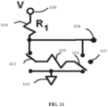
- FIG. 11 depicts an embodiment in which one side of the sensor is attached to a single pole triple throw switch 1125.
- third position 1127 on triple throw switch 1125 can be an open node that does not have an electrical connection.
- switch 1125 By controlling switch 1125 to be in third position 1127, there would be zero external electrical current flowing through sensor 1120, which would prevent the migration of ions through the elongated ion-exchange material.
- the advantage to using a system like that depicted in FIG. 11 is that by independently controlling switches 1122 and 1125, it is possible to apply three states to sensor 1120. Either electrical current passes in one direction through sensor 1120 or it passes in the opposite direction or there is no electrical current flow.
- FIG. 12 depicts the use of a circuit called a sample and hold 1234 to latch measurements of sensor resistance.
- single pole single throw switch 1226 closes momentarily to connect from voltage divider node 1218 to charge capacitor 1228.
- Single pole single throw switch 1226 then opens, causing the voltage to be held constant on capacitor 1228.
- Operational amplifier 1230 connected in a so-called emitter follower configuration, has a very high input impedance and a very low output impedance, serving as a buffer to yield output 1232.
- the advantage to using switch 1226 to latch a voltage to output 1232 of the sample and hold 1234 is that when the positions of switches 1222 and 1224 are changing, the voltage at node 1218 may not be stable.
- switch 1226 can be controlled to allow modification of the output only when the input is stable.
- the voltage at output 1232 is representative of the membrane resistance and can be used in a control algorithm for managing water softening.
- the voltage at output 1232 is also representative of the conductance since electrical resistance and electrical conductance are reciprocals. If the voltage measurement for a given time sample, t, is v(t), this value and past measurements, v(t-1), v(t-2), etc can be used to construct a control algorithm.
- the conductivity decreased 20% in 480 minutes.
- Nafion 117 membrane was tested in the planar sensor illustrated in FIG. 1 .
- the conductivity decreased 20% in 150 minutes.
- Neosepta CMX a 0.18-mm-thick cation-exchange membrane, Neosepta CMX, was tested in the planar sensor illustrated in FIG. 1 .
- the conductivity decreased 20% in 40 minutes.
- Cation-exchange fibers were tested in the sensor illustrated in FIG. 6 .
- the conductivity decreased 20% in 6 minutes.
Landscapes
- Chemical & Material Sciences (AREA)
- Life Sciences & Earth Sciences (AREA)
- Engineering & Computer Science (AREA)
- Organic Chemistry (AREA)
- Health & Medical Sciences (AREA)
- Physics & Mathematics (AREA)
- General Physics & Mathematics (AREA)
- Hydrology & Water Resources (AREA)
- Environmental & Geological Engineering (AREA)
- Water Supply & Treatment (AREA)
- Immunology (AREA)
- Analytical Chemistry (AREA)
- Biochemistry (AREA)
- General Health & Medical Sciences (AREA)
- Pathology (AREA)
- Chemical Kinetics & Catalysis (AREA)
- Electrochemistry (AREA)
- Medicinal Chemistry (AREA)
- Food Science & Technology (AREA)
- Investigating Or Analyzing Materials By The Use Of Electric Means (AREA)
- Treatment Of Water By Ion Exchange (AREA)
Claims (9)
- Capteur destiné à évaluer la composition ionique d'une solution, comprenant :(i) un bloc non conducteur (60) qui forme le boîtier du capteur, ledit bloc formant une cavité (61) à travers laquelle s'écoule une solution électrolytique, un premier orifice (63) relié à la cavité à travers lequel la solution électrolytique pénètre dans la cavité, et un second orifice (64) relié à la cavité à travers lequel la solution électrolytique sort de la cavité ;(ii) une matière échangeuse d'ions en continu comprenant deux ou plusieurs fibres échangeuses d'ions (62) formant un faisceau de fibres situé dans la cavité, dans lequel une extrémité du faisceau de fibres est en contact électrique avec une première électrode et l'autre extrémité est en contact électrique avec une seconde électrode, une distance prédéterminée séparant la première électrode de la seconde électrode ; et(iii) la première et la seconde électrodes reliées à un dispositif permettant de mesurer la conductivité électrique aux bornes des fibres échangeuses d'ions.
- Capteur selon la revendication 1, comprenant en outre un diaphragme (30) situé dans la cavité, ledit diaphragme étant configuré, sous l'effet d'une pression exercée sur le diaphragme, pour déplacer le fluide de la cavité afin d'éliminer le fluide et servir de voie de passage alternative du courant électrique entre les électrodes, de préférence le diaphragme étant relié à un actionneur (53).
- Capteur selon la revendication 2, dans lequel l'actionneur (53) est un actionneur électrique, hydraulique, pneumatique ou mécanique.
- Capteur selon l'une quelconque des revendications 1 à 3, comprenant en outre un dispositif de régulation de débit configuré pour réguler l'écoulement du fluide à travers le capteur.
- Système adoucisseur d'eau comprenant un appareil adoucisseur relié de manière fluidique à un ou plusieurs capteurs, selon la description de l'une quelconque des revendications 1 à 4.
- Système selon la revendication 5, dans lequel un capteur selon la revendication 1 est situé de telle sorte qu'une partie du fluide qui sort de l'adoucisseur d'eau traverse le capteur.
- Système selon la revendication 5, dans lequel un capteur selon la revendication 1 est situé de telle sorte qu'une partie du fluide qui traverse l'adoucisseur d'eau passe par le capteur au cour de son passage dans l'adoucisseur.
- Procédé, destiné à détecter un changement survenant dans la composition ionique en utilisant un capteur selon la revendication 1, consistant à :(a) mesurer une première tension à un premier instant entre les électrodes reliées à la matière ou surface échangeuse d'ions en continu qui (i) fait passer un courant électrique, (ii) est électriquement en série avec une résistance, et (iii) est en contact avec le fluide où la tension aux bornes de la matière ou surface échangeuse d'ions est proportionnelle à la conductivité électrique de la matière échangeuse d'ions ;(b) mesurer une seconde tension à un second instant entre les électrodes reliées à la matière ou surface échangeuse d'ions en continu qui (i) fait passer un courant électrique, (ii) est électriquement en série avec une résistance, et (iii) est en contact avec le fluide ; et(c) déterminer le changement survenant dans la composition ionique du fluide, sur la base d'une différence apparente entre la première et la seconde tensions.
- Procédé selon la revendication 8, consistant en outre à évacuer l'échantillon de fluide du capteur, au bout d'un temps prédéterminé avant de mesurer la première et la seconde tensions.
Applications Claiming Priority (3)
| Application Number | Priority Date | Filing Date | Title |
|---|---|---|---|
| US201461949155P | 2014-03-06 | 2014-03-06 | |
| EP15758709.8A EP3114086B1 (fr) | 2014-03-06 | 2015-03-06 | Procédés et dispositifs de mesure de la conductivité de fluides |
| PCT/US2015/019167 WO2015134867A1 (fr) | 2014-03-06 | 2015-03-06 | Procédés et dispositifs de mesure de la conductivité de fluides |
Related Parent Applications (2)
| Application Number | Title | Priority Date | Filing Date |
|---|---|---|---|
| EP15758709.8A Division EP3114086B1 (fr) | 2014-03-06 | 2015-03-06 | Procédés et dispositifs de mesure de la conductivité de fluides |
| EP15758709.8A Division-Into EP3114086B1 (fr) | 2014-03-06 | 2015-03-06 | Procédés et dispositifs de mesure de la conductivité de fluides |
Publications (2)
| Publication Number | Publication Date |
|---|---|
| EP3578518A1 EP3578518A1 (fr) | 2019-12-11 |
| EP3578518B1 true EP3578518B1 (fr) | 2024-06-26 |
Family
ID=54055910
Family Applications (2)
| Application Number | Title | Priority Date | Filing Date |
|---|---|---|---|
| EP15758709.8A Active EP3114086B1 (fr) | 2014-03-06 | 2015-03-06 | Procédés et dispositifs de mesure de la conductivité de fluides |
| EP19189569.7A Active EP3578518B1 (fr) | 2014-03-06 | 2015-03-06 | Capteur pour évaluer la composition ionique d'une solution, un adoucisseur d'eau connecté au capteur et une méthode pour détecter le changement de composition ionique à l'aide du capteur |
Family Applications Before (1)
| Application Number | Title | Priority Date | Filing Date |
|---|---|---|---|
| EP15758709.8A Active EP3114086B1 (fr) | 2014-03-06 | 2015-03-06 | Procédés et dispositifs de mesure de la conductivité de fluides |
Country Status (6)
| Country | Link |
|---|---|
| US (1) | US9778299B2 (fr) |
| EP (2) | EP3114086B1 (fr) |
| JP (1) | JP2017508990A (fr) |
| CN (1) | CN106255665B (fr) |
| AU (2) | AU2015226950B2 (fr) |
| WO (1) | WO2015134867A1 (fr) |
Families Citing this family (7)
| Publication number | Priority date | Publication date | Assignee | Title |
|---|---|---|---|---|
| EP3114086B1 (fr) * | 2014-03-06 | 2019-09-11 | The Board of Regents of The University of Texas System | Procédés et dispositifs de mesure de la conductivité de fluides |
| US10617315B2 (en) | 2016-09-30 | 2020-04-14 | Microsoft Technology Licensing, Llc | Detecting bipotential with an ionic varistor |
| CN107632046B (zh) * | 2017-09-08 | 2019-11-26 | 中国矿业大学 | 一种轴承外套圈硬度扫频涡流分选方法 |
| USD865925S1 (en) | 2018-08-31 | 2019-11-05 | Rheem Manufacturing Company | Tankless water heater enclosure |
| US11231182B2 (en) | 2018-12-19 | 2022-01-25 | Rheem Manufacturing Company | Water heater with hardness detection system |
| CN109490636B (zh) * | 2018-12-26 | 2024-04-26 | 上海简逸生物科技有限公司 | 一种溶液冻结及融化过程的电导率变化测试仪 |
| US11667542B2 (en) | 2020-03-31 | 2023-06-06 | Ecowater Systems Llc | Longitudinal in-situ impedance and resin monitoring sensor, and method of measuring and tracking the movement of hardness in a water softener utilizing the same |
Citations (1)
| Publication number | Priority date | Publication date | Assignee | Title |
|---|---|---|---|---|
| EP0605714B1 (fr) * | 1992-07-27 | 1998-11-25 | Dionex Corporation | Systeme de traitement electrochimique prealable pour l'analyse d'un echantillon liquide |
Family Cites Families (63)
| Publication number | Priority date | Publication date | Assignee | Title |
|---|---|---|---|---|
| US3176844A (en) * | 1961-03-14 | 1965-04-06 | Honeywell Inc | Control apparatus |
| GB1286677A (en) * | 1968-09-19 | 1972-08-23 | Sintex Organico Ind S A | Electronic apparatus for ion exchange process control |
| US3768649A (en) * | 1971-07-15 | 1973-10-30 | Fleckenstein A J | Regeneration sensing system |
| US3964999A (en) * | 1973-09-19 | 1976-06-22 | Beckman Instruments, Inc. | Determination of sodium form water softener breakthrough |
| US3934193A (en) * | 1973-12-17 | 1976-01-20 | Purdue Research Foundation | Electrolytic conductivity detector |
| US4032296A (en) * | 1973-12-17 | 1977-06-28 | Purdue Research Foundation | Electrolytic conductivity detector system |
| US4032452A (en) * | 1975-11-13 | 1977-06-28 | Sybron Corporation | Electrically regenerated ion exchange system |
| US4158628A (en) * | 1978-06-05 | 1979-06-19 | Fleckensteim Andrew J | Sensor device for water softener system |
| US4320010A (en) * | 1980-01-24 | 1982-03-16 | Sys-Tec, Inc. | Regeneration detector for water softeners |
| US4403039A (en) * | 1980-10-29 | 1983-09-06 | Yokogawa Hokushin Electric Works | Method and apparatus for analysis of ionic species |
| US4491798A (en) * | 1981-12-21 | 1985-01-01 | Palmer James K | System for measuring conductivity of a liquid |
| JPS6039434B2 (ja) * | 1982-07-13 | 1985-09-05 | 株式会社荏原製作所 | イオン交換繊維を用いる濾過脱塩方法 |
| US4672322A (en) * | 1984-08-24 | 1987-06-09 | Milton Roy Company | High sensitivity conductivity detector |
| AU587988B2 (en) * | 1984-10-04 | 1989-09-07 | Dionex Corporation | Modified membrane suppressor and method of use |
| US4668386A (en) * | 1985-08-26 | 1987-05-26 | Autotrol Corporation | Water quality monitor |
| GB8522207D0 (en) * | 1985-09-06 | 1985-10-09 | Kodak Ltd | Ion-sensitive electrochemical sensor |
| US4935207A (en) * | 1986-04-01 | 1990-06-19 | The Johns Hopkins University | Capacitive chemical sensor using an ion exchange surface |
| US4880513A (en) * | 1986-06-20 | 1989-11-14 | The Graver Company | Method and apparatus for generating acid and base regenerants and the use thereof to regenerate ion-exchange resins |
| JPH02307515A (ja) * | 1989-05-19 | 1990-12-20 | Babcock Hitachi Kk | 電気透析装置 |
| US5491097A (en) * | 1989-06-15 | 1996-02-13 | Biocircuits Corporation | Analyte detection with multilayered bioelectronic conductivity sensors |
| US5078854A (en) * | 1990-01-22 | 1992-01-07 | Mallinckrodt Sensor Systems, Inc. | Polarographic chemical sensor with external reference electrode |
| JPH0547853U (ja) * | 1991-11-28 | 1993-06-25 | 東ソー株式会社 | イオン交換膜の抵抗・輸率測定装置 |
| CA2087481C (fr) * | 1992-02-10 | 2001-09-04 | John R. Stillian | Systeme de chromatographie par echange d'ions utilisant la suppression electrochimique et le recyclage de l'effluent detecteur |
| US5322602A (en) * | 1993-01-28 | 1994-06-21 | Teledyne Industries, Inc. | Gas sensors |
| DE59807440D1 (de) * | 1997-09-03 | 2003-04-17 | Aweco Appliance Sys Gmbh & Co | Vorrichtung zur Wasserenthärtung |
| FR2771400B1 (fr) * | 1997-11-27 | 2000-01-07 | Bwt France | Procede d'optimisation du cycle de fonctionnement d'une unite de traitement d'eau |
| US5990684A (en) * | 1997-12-02 | 1999-11-23 | Merrill; John H. | Method and apparatus for continuously monitoring an aqueous flow to detect and quantify ions |
| US6200477B1 (en) * | 1998-05-06 | 2001-03-13 | Alltech Associates, Inc. | Continuously regenerated and integrated suppressor and detector for suppressed ion chromatography and method |
| US6077434A (en) * | 1999-01-15 | 2000-06-20 | Dionex Corporation | Current-efficient suppressors and method of use |
| US6258263B1 (en) * | 1999-09-17 | 2001-07-10 | The University Of Cincinnati | Liquid chromatograph on a chip |
| JP4277433B2 (ja) * | 2000-08-02 | 2009-06-10 | 東ソー株式会社 | サプレッサ内のイオン交換材を交換するイオンクロマトグラフシステム及びサプレッサ手段 |
| JP4766784B2 (ja) * | 2001-06-22 | 2011-09-07 | 北陸電気工業株式会社 | 湿度センサ |
| US6783684B2 (en) * | 2001-09-20 | 2004-08-31 | Paul A. Teel, Jr. | Water softening apparatus and associated method for sensing depletion of salt in a brine tank |
| JP2003093825A (ja) * | 2001-09-27 | 2003-04-02 | Ebara Corp | ガス除去方法及びガス除去フィルタ |
| US7582482B2 (en) * | 2002-09-03 | 2009-09-01 | Dionex Corporation | Continuous ion species removal device and method |
| US20030180186A1 (en) * | 2003-05-19 | 2003-09-25 | Carson William W. | Process and device for continuous tonic monitoring of aqueous solutions |
| US9181110B2 (en) * | 2004-01-30 | 2015-11-10 | Peter S. Cartwright | Water softener using nanofiltration to reclaim a portion of the regenerating solution |
| CN101704583A (zh) * | 2004-05-24 | 2010-05-12 | 方太海德有限公司 | 浮岛 |
| CN2727150Y (zh) * | 2004-06-24 | 2005-09-21 | 上海万森水处理有限公司 | 浸没式紫外线水体杀菌器 |
| US7329338B2 (en) * | 2004-10-27 | 2008-02-12 | General Electric Company | Conductivity sensor for an ion exchange water softener |
| JP2006138737A (ja) * | 2004-11-12 | 2006-06-01 | Fanuc Ltd | 比抵抗検出器及び比抵抗検出装置 |
| US7329346B2 (en) * | 2005-02-23 | 2008-02-12 | Dionex Corporation | Ion chromatography system using catalytic gas elimination |
| US7709265B2 (en) * | 2005-03-24 | 2010-05-04 | Johnsondiversey, Inc. | Method and system for measuring water hardness |
| US7892848B2 (en) * | 2005-04-14 | 2011-02-22 | Trovion Singapore Pte. Ltd., Co. | Method of ion chromatography wherein a specialized electrodeionization apparatus is used |
| US7872225B2 (en) * | 2006-08-25 | 2011-01-18 | Perkinelmer Health Sciences, Inc. | Sample component trapping, release, and separation with membrane assemblies interfaced to electrospray mass spectrometry |
| US7780833B2 (en) * | 2005-07-26 | 2010-08-24 | John Hawkins | Electrochemical ion exchange with textured membranes and cartridge |
| WO2007044609A1 (fr) * | 2005-10-06 | 2007-04-19 | Pionetics Corporation | Traitement electrochimique de fluides par echange d'ions |
| US7582205B1 (en) * | 2005-12-28 | 2009-09-01 | Fiscella Jr Anthony S | Brine mixing apparatus |
| JP2007240366A (ja) * | 2006-03-09 | 2007-09-20 | Kurita Water Ind Ltd | 全炭酸濃度測定装置及び測定方法 |
| JP2008076227A (ja) * | 2006-09-21 | 2008-04-03 | Osaka Univ | 生体関連物質の分析方法および分析装置 |
| CN101187054A (zh) * | 2007-09-18 | 2008-05-28 | 上海轻工业研究所有限公司 | 在线离子交换回收镀镍废水的控制装置 |
| DE102007059058C5 (de) * | 2007-12-06 | 2014-11-27 | Judo Wasseraufbereitung Gmbh | Verfahren zum Betrieb einer Wasserenthärtungsanlage mit zwei Kalibrierkennlinien und zugehörige Wasserenthärtungsanlage |
| ATE556319T1 (de) * | 2008-02-21 | 2012-05-15 | Shimadzu Corp | Suppressor mit nutzung eines mikroionenaustauschröhrchens und ionenchromatograph mit nutzung davon |
| US7585679B1 (en) * | 2008-02-22 | 2009-09-08 | Dionex Corporation | Ion chromatography system with flow-delay eluent recycle |
| JP5120130B2 (ja) * | 2008-07-31 | 2013-01-16 | 株式会社ノーリツ | 電解液の濃度測定装置及び軟水化システム |
| SG169305A1 (en) * | 2009-08-26 | 2011-03-30 | Siemens Pte Ltd | Ion exchange membranes |
| CA2775712A1 (fr) * | 2009-09-29 | 2011-04-07 | Pentair Residential Filtration, Llc | Systeme et procede de traitement de l'eau a deux cuves |
| DE102009055007A1 (de) * | 2009-12-18 | 2011-06-22 | Judo Wasseraufbereitung GmbH, 71364 | Rohwasserhärtebestimmung in einer Wasserbehandlungsanlage über die Leitfähigkeit des Weich- oder Verschnittwassers |
| EP2335941B1 (fr) * | 2009-12-18 | 2014-02-26 | Heidelberger Druckmaschinen AG | Réglage de dureté par agent d'humification |
| WO2013061293A1 (fr) * | 2011-10-28 | 2013-05-02 | Koninklijke Philips Electronics N.V. | Capteur de mesure pour gaz soluble dans un fluide |
| US9914651B2 (en) * | 2013-05-08 | 2018-03-13 | Dionex Corporation | Current efficient electrolytic device and method |
| US9284205B2 (en) * | 2013-12-24 | 2016-03-15 | Donald S. Hofmann | Apparatus providing softened makeup water for cooling system |
| EP3114086B1 (fr) * | 2014-03-06 | 2019-09-11 | The Board of Regents of The University of Texas System | Procédés et dispositifs de mesure de la conductivité de fluides |
-
2015
- 2015-03-06 EP EP15758709.8A patent/EP3114086B1/fr active Active
- 2015-03-06 JP JP2016573699A patent/JP2017508990A/ja active Pending
- 2015-03-06 EP EP19189569.7A patent/EP3578518B1/fr active Active
- 2015-03-06 WO PCT/US2015/019167 patent/WO2015134867A1/fr not_active Ceased
- 2015-03-06 CN CN201580022805.9A patent/CN106255665B/zh active Active
- 2015-03-06 AU AU2015226950A patent/AU2015226950B2/en active Active
- 2015-03-06 US US14/640,632 patent/US9778299B2/en active Active
-
2020
- 2020-01-30 AU AU2020200670A patent/AU2020200670B2/en active Active
Patent Citations (1)
| Publication number | Priority date | Publication date | Assignee | Title |
|---|---|---|---|---|
| EP0605714B1 (fr) * | 1992-07-27 | 1998-11-25 | Dionex Corporation | Systeme de traitement electrochimique prealable pour l'analyse d'un echantillon liquide |
Also Published As
| Publication number | Publication date |
|---|---|
| WO2015134867A1 (fr) | 2015-09-11 |
| EP3578518A1 (fr) | 2019-12-11 |
| AU2015226950B2 (en) | 2019-10-31 |
| EP3114086B1 (fr) | 2019-09-11 |
| AU2020200670B2 (en) | 2021-06-24 |
| EP3114086A1 (fr) | 2017-01-11 |
| AU2015226950A1 (en) | 2016-09-22 |
| CN106255665A (zh) | 2016-12-21 |
| EP3114086A4 (fr) | 2017-10-11 |
| CN106255665B (zh) | 2019-07-19 |
| JP2017508990A (ja) | 2017-03-30 |
| US9778299B2 (en) | 2017-10-03 |
| AU2020200670A1 (en) | 2020-03-19 |
| US20150276836A1 (en) | 2015-10-01 |
Similar Documents
| Publication | Publication Date | Title |
|---|---|---|
| AU2020200670B2 (en) | Methods and devices for measuring conductivity of fluids | |
| CN104703697B (zh) | 高性能的阴离子交换膜及其制造方法 | |
| TWI480094B (zh) | 電滲析裝置及製程 | |
| CN109752426B (zh) | 软水机、用于软水机的水质硬度检测装置和检测方法 | |
| US3964999A (en) | Determination of sodium form water softener breakthrough | |
| EP4144281A1 (fr) | Procédé de commande et appareil de commande de lave-vaisselle | |
| EP3366373B1 (fr) | Adoucisseur d'eau et son procédé de fonctionnement | |
| Xu et al. | A simple evaluation of microstructure and transport parameters of ion-exchange membranes from conductivity measurements | |
| KR101942477B1 (ko) | 이온교환수지 교체시기 판단 기능을 갖는 연수기 | |
| Monzie et al. | Mass transfer investigations in electrodeionization processes using the microcolumn technique | |
| US3869382A (en) | Method and apparatus for determining exhaustion of a mass of ion exchange material and a device using the same | |
| US7556738B2 (en) | Method for determining the duration of a brine/slow rinse cycle for a water conditioner | |
| WO2002014850A9 (fr) | Procede et dispositif de controle ionique continu de solutions aqueuses | |
| JP2007192702A (ja) | イオンセンサー、再生時期の判定方法、軟化器、イオン分析装置及びイオン分析方法 | |
| US9783433B2 (en) | Water treatment valve control system with rotary position sensor | |
| JP7080617B2 (ja) | イオン交換装置、イオン交換樹脂の交換時期予測方法、及びイオン交換樹脂の交換時期予測装置 | |
| KR100696829B1 (ko) | 연수기의 연수 농도 측정 장치 | |
| JPH07270212A (ja) | 塩水タンクの水位および塩水濃度検知装置 | |
| JPH06288812A (ja) | 塩水タンクの水位および塩水濃度検知装置 | |
| CN119178941A (zh) | 电容去离子装置的失效检测方法、装置及水家电设备 | |
| JPH058518Y2 (fr) | ||
| JPS61120959A (ja) | 硬水検知装置 | |
| Boundy et al. | Conduction and Mass Transfer in Reinforced Cation Exchange Membranes | |
| JP2017051907A (ja) | イオン濃度調整装置およびイオン濃度調整方法 | |
| JPH01228587A (ja) | 硬水軟化装置の硬度洩れ警報手段 |
Legal Events
| Date | Code | Title | Description |
|---|---|---|---|
| PUAI | Public reference made under article 153(3) epc to a published international application that has entered the european phase |
Free format text: ORIGINAL CODE: 0009012 |
|
| STAA | Information on the status of an ep patent application or granted ep patent |
Free format text: STATUS: THE APPLICATION HAS BEEN PUBLISHED |
|
| AC | Divisional application: reference to earlier application |
Ref document number: 3114086 Country of ref document: EP Kind code of ref document: P |
|
| AK | Designated contracting states |
Kind code of ref document: A1 Designated state(s): AL AT BE BG CH CY CZ DE DK EE ES FI FR GB GR HR HU IE IS IT LI LT LU LV MC MK MT NL NO PL PT RO RS SE SI SK SM TR |
|
| STAA | Information on the status of an ep patent application or granted ep patent |
Free format text: STATUS: REQUEST FOR EXAMINATION WAS MADE |
|
| 17P | Request for examination filed |
Effective date: 20200608 |
|
| RBV | Designated contracting states (corrected) |
Designated state(s): AL AT BE BG CH CY CZ DE DK EE ES FI FR GB GR HR HU IE IS IT LI LT LU LV MC MK MT NL NO PL PT RO RS SE SI SK SM TR |
|
| STAA | Information on the status of an ep patent application or granted ep patent |
Free format text: STATUS: EXAMINATION IS IN PROGRESS |
|
| 17Q | First examination report despatched |
Effective date: 20201020 |
|
| GRAP | Despatch of communication of intention to grant a patent |
Free format text: ORIGINAL CODE: EPIDOSNIGR1 |
|
| STAA | Information on the status of an ep patent application or granted ep patent |
Free format text: STATUS: GRANT OF PATENT IS INTENDED |
|
| INTG | Intention to grant announced |
Effective date: 20230901 |
|
| GRAJ | Information related to disapproval of communication of intention to grant by the applicant or resumption of examination proceedings by the epo deleted |
Free format text: ORIGINAL CODE: EPIDOSDIGR1 |
|
| STAA | Information on the status of an ep patent application or granted ep patent |
Free format text: STATUS: EXAMINATION IS IN PROGRESS |
|
| INTC | Intention to grant announced (deleted) | ||
| RAP3 | Party data changed (applicant data changed or rights of an application transferred) |
Owner name: THE BOARD OF REGENTS OF THE UNIVERSITY OF TEXAS SYSTEM |
|
| GRAP | Despatch of communication of intention to grant a patent |
Free format text: ORIGINAL CODE: EPIDOSNIGR1 |
|
| STAA | Information on the status of an ep patent application or granted ep patent |
Free format text: STATUS: GRANT OF PATENT IS INTENDED |
|
| INTG | Intention to grant announced |
Effective date: 20231123 |
|
| GRAS | Grant fee paid |
Free format text: ORIGINAL CODE: EPIDOSNIGR3 |
|
| GRAA | (expected) grant |
Free format text: ORIGINAL CODE: 0009210 |
|
| STAA | Information on the status of an ep patent application or granted ep patent |
Free format text: STATUS: THE PATENT HAS BEEN GRANTED |
|
| AC | Divisional application: reference to earlier application |
Ref document number: 3114086 Country of ref document: EP Kind code of ref document: P |
|
| AK | Designated contracting states |
Kind code of ref document: B1 Designated state(s): AL AT BE BG CH CY CZ DE DK EE ES FI FR GB GR HR HU IE IS IT LI LT LU LV MC MK MT NL NO PL PT RO RS SE SI SK SM TR |
|
| REG | Reference to a national code |
Ref country code: GB Ref legal event code: FG4D |
|
| REG | Reference to a national code |
Ref country code: CH Ref legal event code: EP |
|
| REG | Reference to a national code |
Ref country code: DE Ref legal event code: R096 Ref document number: 602015089080 Country of ref document: DE |
|
| P01 | Opt-out of the competence of the unified patent court (upc) registered |
Free format text: CASE NUMBER: APP_36041/2024 Effective date: 20240617 |
|
| PG25 | Lapsed in a contracting state [announced via postgrant information from national office to epo] |
Ref country code: BG Free format text: LAPSE BECAUSE OF FAILURE TO SUBMIT A TRANSLATION OF THE DESCRIPTION OR TO PAY THE FEE WITHIN THE PRESCRIBED TIME-LIMIT Effective date: 20240626 |
|
| PG25 | Lapsed in a contracting state [announced via postgrant information from national office to epo] |
Ref country code: HR Free format text: LAPSE BECAUSE OF FAILURE TO SUBMIT A TRANSLATION OF THE DESCRIPTION OR TO PAY THE FEE WITHIN THE PRESCRIBED TIME-LIMIT Effective date: 20240626 Ref country code: FI Free format text: LAPSE BECAUSE OF FAILURE TO SUBMIT A TRANSLATION OF THE DESCRIPTION OR TO PAY THE FEE WITHIN THE PRESCRIBED TIME-LIMIT Effective date: 20240626 |
|
| REG | Reference to a national code |
Ref country code: LT Ref legal event code: MG9D |
|
| PG25 | Lapsed in a contracting state [announced via postgrant information from national office to epo] |
Ref country code: GR Free format text: LAPSE BECAUSE OF FAILURE TO SUBMIT A TRANSLATION OF THE DESCRIPTION OR TO PAY THE FEE WITHIN THE PRESCRIBED TIME-LIMIT Effective date: 20240927 |
|
| PG25 | Lapsed in a contracting state [announced via postgrant information from national office to epo] |
Ref country code: LV Free format text: LAPSE BECAUSE OF FAILURE TO SUBMIT A TRANSLATION OF THE DESCRIPTION OR TO PAY THE FEE WITHIN THE PRESCRIBED TIME-LIMIT Effective date: 20240626 |
|
| REG | Reference to a national code |
Ref country code: NL Ref legal event code: MP Effective date: 20240626 |
|
| PG25 | Lapsed in a contracting state [announced via postgrant information from national office to epo] |
Ref country code: NO Free format text: LAPSE BECAUSE OF FAILURE TO SUBMIT A TRANSLATION OF THE DESCRIPTION OR TO PAY THE FEE WITHIN THE PRESCRIBED TIME-LIMIT Effective date: 20240926 Ref country code: LV Free format text: LAPSE BECAUSE OF FAILURE TO SUBMIT A TRANSLATION OF THE DESCRIPTION OR TO PAY THE FEE WITHIN THE PRESCRIBED TIME-LIMIT Effective date: 20240626 Ref country code: HR Free format text: LAPSE BECAUSE OF FAILURE TO SUBMIT A TRANSLATION OF THE DESCRIPTION OR TO PAY THE FEE WITHIN THE PRESCRIBED TIME-LIMIT Effective date: 20240626 Ref country code: GR Free format text: LAPSE BECAUSE OF FAILURE TO SUBMIT A TRANSLATION OF THE DESCRIPTION OR TO PAY THE FEE WITHIN THE PRESCRIBED TIME-LIMIT Effective date: 20240927 Ref country code: FI Free format text: LAPSE BECAUSE OF FAILURE TO SUBMIT A TRANSLATION OF THE DESCRIPTION OR TO PAY THE FEE WITHIN THE PRESCRIBED TIME-LIMIT Effective date: 20240626 Ref country code: BG Free format text: LAPSE BECAUSE OF FAILURE TO SUBMIT A TRANSLATION OF THE DESCRIPTION OR TO PAY THE FEE WITHIN THE PRESCRIBED TIME-LIMIT Effective date: 20240626 Ref country code: RS Free format text: LAPSE BECAUSE OF FAILURE TO SUBMIT A TRANSLATION OF THE DESCRIPTION OR TO PAY THE FEE WITHIN THE PRESCRIBED TIME-LIMIT Effective date: 20240926 |
|
| PG25 | Lapsed in a contracting state [announced via postgrant information from national office to epo] |
Ref country code: NL Free format text: LAPSE BECAUSE OF FAILURE TO SUBMIT A TRANSLATION OF THE DESCRIPTION OR TO PAY THE FEE WITHIN THE PRESCRIBED TIME-LIMIT Effective date: 20240626 |
|
| REG | Reference to a national code |
Ref country code: AT Ref legal event code: MK05 Ref document number: 1697576 Country of ref document: AT Kind code of ref document: T Effective date: 20240626 |
|
| PG25 | Lapsed in a contracting state [announced via postgrant information from national office to epo] |
Ref country code: NL Free format text: LAPSE BECAUSE OF FAILURE TO SUBMIT A TRANSLATION OF THE DESCRIPTION OR TO PAY THE FEE WITHIN THE PRESCRIBED TIME-LIMIT Effective date: 20240626 |
|
| PG25 | Lapsed in a contracting state [announced via postgrant information from national office to epo] |
Ref country code: PT Free format text: LAPSE BECAUSE OF FAILURE TO SUBMIT A TRANSLATION OF THE DESCRIPTION OR TO PAY THE FEE WITHIN THE PRESCRIBED TIME-LIMIT Effective date: 20241028 |
|
| PG25 | Lapsed in a contracting state [announced via postgrant information from national office to epo] |
Ref country code: PT Free format text: LAPSE BECAUSE OF FAILURE TO SUBMIT A TRANSLATION OF THE DESCRIPTION OR TO PAY THE FEE WITHIN THE PRESCRIBED TIME-LIMIT Effective date: 20241028 |
|
| PG25 | Lapsed in a contracting state [announced via postgrant information from national office to epo] |
Ref country code: PL Free format text: LAPSE BECAUSE OF FAILURE TO SUBMIT A TRANSLATION OF THE DESCRIPTION OR TO PAY THE FEE WITHIN THE PRESCRIBED TIME-LIMIT Effective date: 20240626 |
|
| PG25 | Lapsed in a contracting state [announced via postgrant information from national office to epo] |
Ref country code: EE Free format text: LAPSE BECAUSE OF FAILURE TO SUBMIT A TRANSLATION OF THE DESCRIPTION OR TO PAY THE FEE WITHIN THE PRESCRIBED TIME-LIMIT Effective date: 20240626 |
|
| PG25 | Lapsed in a contracting state [announced via postgrant information from national office to epo] |
Ref country code: IS Free format text: LAPSE BECAUSE OF FAILURE TO SUBMIT A TRANSLATION OF THE DESCRIPTION OR TO PAY THE FEE WITHIN THE PRESCRIBED TIME-LIMIT Effective date: 20241026 Ref country code: AT Free format text: LAPSE BECAUSE OF FAILURE TO SUBMIT A TRANSLATION OF THE DESCRIPTION OR TO PAY THE FEE WITHIN THE PRESCRIBED TIME-LIMIT Effective date: 20240626 |
|
| PG25 | Lapsed in a contracting state [announced via postgrant information from national office to epo] |
Ref country code: CZ Free format text: LAPSE BECAUSE OF FAILURE TO SUBMIT A TRANSLATION OF THE DESCRIPTION OR TO PAY THE FEE WITHIN THE PRESCRIBED TIME-LIMIT Effective date: 20240626 |
|
| PG25 | Lapsed in a contracting state [announced via postgrant information from national office to epo] |
Ref country code: RO Free format text: LAPSE BECAUSE OF FAILURE TO SUBMIT A TRANSLATION OF THE DESCRIPTION OR TO PAY THE FEE WITHIN THE PRESCRIBED TIME-LIMIT Effective date: 20240626 Ref country code: SK Free format text: LAPSE BECAUSE OF FAILURE TO SUBMIT A TRANSLATION OF THE DESCRIPTION OR TO PAY THE FEE WITHIN THE PRESCRIBED TIME-LIMIT Effective date: 20240626 |
|
| PG25 | Lapsed in a contracting state [announced via postgrant information from national office to epo] |
Ref country code: ES Free format text: LAPSE BECAUSE OF FAILURE TO SUBMIT A TRANSLATION OF THE DESCRIPTION OR TO PAY THE FEE WITHIN THE PRESCRIBED TIME-LIMIT Effective date: 20240626 Ref country code: SM Free format text: LAPSE BECAUSE OF FAILURE TO SUBMIT A TRANSLATION OF THE DESCRIPTION OR TO PAY THE FEE WITHIN THE PRESCRIBED TIME-LIMIT Effective date: 20240626 |
|
| PG25 | Lapsed in a contracting state [announced via postgrant information from national office to epo] |
Ref country code: SM Free format text: LAPSE BECAUSE OF FAILURE TO SUBMIT A TRANSLATION OF THE DESCRIPTION OR TO PAY THE FEE WITHIN THE PRESCRIBED TIME-LIMIT Effective date: 20240626 Ref country code: SK Free format text: LAPSE BECAUSE OF FAILURE TO SUBMIT A TRANSLATION OF THE DESCRIPTION OR TO PAY THE FEE WITHIN THE PRESCRIBED TIME-LIMIT Effective date: 20240626 Ref country code: RO Free format text: LAPSE BECAUSE OF FAILURE TO SUBMIT A TRANSLATION OF THE DESCRIPTION OR TO PAY THE FEE WITHIN THE PRESCRIBED TIME-LIMIT Effective date: 20240626 Ref country code: PL Free format text: LAPSE BECAUSE OF FAILURE TO SUBMIT A TRANSLATION OF THE DESCRIPTION OR TO PAY THE FEE WITHIN THE PRESCRIBED TIME-LIMIT Effective date: 20240626 Ref country code: IS Free format text: LAPSE BECAUSE OF FAILURE TO SUBMIT A TRANSLATION OF THE DESCRIPTION OR TO PAY THE FEE WITHIN THE PRESCRIBED TIME-LIMIT Effective date: 20241026 Ref country code: ES Free format text: LAPSE BECAUSE OF FAILURE TO SUBMIT A TRANSLATION OF THE DESCRIPTION OR TO PAY THE FEE WITHIN THE PRESCRIBED TIME-LIMIT Effective date: 20240626 Ref country code: EE Free format text: LAPSE BECAUSE OF FAILURE TO SUBMIT A TRANSLATION OF THE DESCRIPTION OR TO PAY THE FEE WITHIN THE PRESCRIBED TIME-LIMIT Effective date: 20240626 Ref country code: CZ Free format text: LAPSE BECAUSE OF FAILURE TO SUBMIT A TRANSLATION OF THE DESCRIPTION OR TO PAY THE FEE WITHIN THE PRESCRIBED TIME-LIMIT Effective date: 20240626 Ref country code: AT Free format text: LAPSE BECAUSE OF FAILURE TO SUBMIT A TRANSLATION OF THE DESCRIPTION OR TO PAY THE FEE WITHIN THE PRESCRIBED TIME-LIMIT Effective date: 20240626 |
|
| PG25 | Lapsed in a contracting state [announced via postgrant information from national office to epo] |
Ref country code: IT Free format text: LAPSE BECAUSE OF FAILURE TO SUBMIT A TRANSLATION OF THE DESCRIPTION OR TO PAY THE FEE WITHIN THE PRESCRIBED TIME-LIMIT Effective date: 20240626 |
|
| REG | Reference to a national code |
Ref country code: DE Ref legal event code: R097 Ref document number: 602015089080 Country of ref document: DE |
|
| PGFP | Annual fee paid to national office [announced via postgrant information from national office to epo] |
Ref country code: DE Payment date: 20250327 Year of fee payment: 11 |
|
| PG25 | Lapsed in a contracting state [announced via postgrant information from national office to epo] |
Ref country code: DK Free format text: LAPSE BECAUSE OF FAILURE TO SUBMIT A TRANSLATION OF THE DESCRIPTION OR TO PAY THE FEE WITHIN THE PRESCRIBED TIME-LIMIT Effective date: 20240626 |
|
| PGFP | Annual fee paid to national office [announced via postgrant information from national office to epo] |
Ref country code: GB Payment date: 20250320 Year of fee payment: 11 |
|
| PLBE | No opposition filed within time limit |
Free format text: ORIGINAL CODE: 0009261 |
|
| STAA | Information on the status of an ep patent application or granted ep patent |
Free format text: STATUS: NO OPPOSITION FILED WITHIN TIME LIMIT |
|
| 26N | No opposition filed |
Effective date: 20250327 |
|
| PG25 | Lapsed in a contracting state [announced via postgrant information from national office to epo] |
Ref country code: SE Free format text: LAPSE BECAUSE OF FAILURE TO SUBMIT A TRANSLATION OF THE DESCRIPTION OR TO PAY THE FEE WITHIN THE PRESCRIBED TIME-LIMIT Effective date: 20240626 |
|
| PG25 | Lapsed in a contracting state [announced via postgrant information from national office to epo] |
Ref country code: MC Free format text: LAPSE BECAUSE OF FAILURE TO SUBMIT A TRANSLATION OF THE DESCRIPTION OR TO PAY THE FEE WITHIN THE PRESCRIBED TIME-LIMIT Effective date: 20240626 |
|
| REG | Reference to a national code |
Ref country code: CH Ref legal event code: H13 Free format text: ST27 STATUS EVENT CODE: U-0-0-H10-H13 (AS PROVIDED BY THE NATIONAL OFFICE) Effective date: 20251023 |
|
| PG25 | Lapsed in a contracting state [announced via postgrant information from national office to epo] |
Ref country code: LU Free format text: LAPSE BECAUSE OF NON-PAYMENT OF DUE FEES Effective date: 20250306 |
|
| REG | Reference to a national code |
Ref country code: BE Ref legal event code: MM Effective date: 20250331 |
|
| PG25 | Lapsed in a contracting state [announced via postgrant information from national office to epo] |
Ref country code: BE Free format text: LAPSE BECAUSE OF NON-PAYMENT OF DUE FEES Effective date: 20250331 |
|
| PG25 | Lapsed in a contracting state [announced via postgrant information from national office to epo] |
Ref country code: CH Free format text: LAPSE BECAUSE OF NON-PAYMENT OF DUE FEES Effective date: 20250331 |
|
| PG25 | Lapsed in a contracting state [announced via postgrant information from national office to epo] |
Ref country code: IE Free format text: LAPSE BECAUSE OF NON-PAYMENT OF DUE FEES Effective date: 20250306 |
|
| PGFP | Annual fee paid to national office [announced via postgrant information from national office to epo] |
Ref country code: FR Payment date: 20260316 Year of fee payment: 12 |