EP3578752B1 - Système intelligent et intégré de complétion de puits présentant plusieurs zones - Google Patents
Système intelligent et intégré de complétion de puits présentant plusieurs zones Download PDFInfo
- Publication number
- EP3578752B1 EP3578752B1 EP19187957.6A EP19187957A EP3578752B1 EP 3578752 B1 EP3578752 B1 EP 3578752B1 EP 19187957 A EP19187957 A EP 19187957A EP 3578752 B1 EP3578752 B1 EP 3578752B1
- Authority
- EP
- European Patent Office
- Prior art keywords
- completion string
- flow control
- control device
- well
- flow
- Prior art date
- Legal status (The legal status is an assumption and is not a legal conclusion. Google has not performed a legal analysis and makes no representation as to the accuracy of the status listed.)
- Active
Links
Images



Classifications
-
- E—FIXED CONSTRUCTIONS
- E21—EARTH OR ROCK DRILLING; MINING
- E21B—EARTH OR ROCK DRILLING; OBTAINING OIL, GAS, WATER, SOLUBLE OR MELTABLE MATERIALS OR A SLURRY OF MINERALS FROM WELLS
- E21B43/00—Methods or apparatus for obtaining oil, gas, water, soluble or meltable materials or a slurry of minerals from wells
- E21B43/12—Methods or apparatus for controlling the flow of the obtained fluid to or in wells
-
- E—FIXED CONSTRUCTIONS
- E21—EARTH OR ROCK DRILLING; MINING
- E21B—EARTH OR ROCK DRILLING; OBTAINING OIL, GAS, WATER, SOLUBLE OR MELTABLE MATERIALS OR A SLURRY OF MINERALS FROM WELLS
- E21B43/00—Methods or apparatus for obtaining oil, gas, water, soluble or meltable materials or a slurry of minerals from wells
- E21B43/14—Obtaining from a multiple-zone well
-
- E—FIXED CONSTRUCTIONS
- E21—EARTH OR ROCK DRILLING; MINING
- E21B—EARTH OR ROCK DRILLING; OBTAINING OIL, GAS, WATER, SOLUBLE OR MELTABLE MATERIALS OR A SLURRY OF MINERALS FROM WELLS
- E21B47/00—Survey of boreholes or wells
- E21B47/06—Measuring temperature or pressure
-
- E—FIXED CONSTRUCTIONS
- E21—EARTH OR ROCK DRILLING; MINING
- E21B—EARTH OR ROCK DRILLING; OBTAINING OIL, GAS, WATER, SOLUBLE OR MELTABLE MATERIALS OR A SLURRY OF MINERALS FROM WELLS
- E21B47/00—Survey of boreholes or wells
- E21B47/10—Locating fluid leaks, intrusions or movements
- E21B47/113—Locating fluid leaks, intrusions or movements using electrical indications; using light radiations
-
- E—FIXED CONSTRUCTIONS
- E21—EARTH OR ROCK DRILLING; MINING
- E21B—EARTH OR ROCK DRILLING; OBTAINING OIL, GAS, WATER, SOLUBLE OR MELTABLE MATERIALS OR A SLURRY OF MINERALS FROM WELLS
- E21B2200/00—Special features related to earth drilling for obtaining oil, gas or water
- E21B2200/02—Down-hole chokes or valves for variably regulating fluid flow
Definitions
- This disclosure relates generally to equipment utilized and operations performed in conjunction with subterranean wells and, in one example described below, more particularly provides a multiple zone integrated intelligent well completion.
- US2009/288838A1 discloses a system for installation in a wellbore which includes a flow control device and a control unit coupled to the flow control device.
- variable flow restricting device is configured to receive fluid which flows through a well screen.
- an optical waveguide is positioned external to a completion string, and one or more pressure sensors sense pressure internal and/or external to the completion string.
- the system can include multiple well screens which filter fluid flowing between a completion string in the well and respective ones of the multiple zones, at least one optical waveguide which senses at least one property of the fluid as it flows between the completion string and at least one of the zones, multiple flow control devices which variably restrict flow of the fluid through respective ones of the multiple well screens, and multiple pressure sensors which sense pressure of the fluid which flows through respective ones of the multiple well screens.
- the completion string can include at least one well screen, at least one flow control device which selectively prevents and permits substantially unrestricted flow through the well screen, and at least one other flow control device which is remotely operable, and which variably restricts flow through the well screen.
- the method comprises: a) closing all of multiple flow control devices connected in the completion string, the completion string including multiple well screens which filter fluid flowing between the completion string and respective ones of multiple earth formation zones, at least one optical waveguide which senses at least one property of the fluid as it flows between the completion string and at least one of the zones, the multiple flow control devices which variably restrict flow of the fluid through respective ones of the multiple well screens, and multiple pressure sensors which sense pressure of the fluid which flows through respective ones of the multiple well screens; b) at least partially opening a selected one of the flow control devices; and c) measuring a change in the property sensed by the optical waveguide and a change in the pressure of the fluid as a result of the opening of the selected one of the flow control devices.
- FIG. 1 Representatively illustrated in FIG. 1 is a well completion system 10 and associated method which can embody principles of this disclosure.
- system 10 and method are merely one example of an application of the principles of this disclosure in practice, and a wide variety of other examples are possible. Therefore, the scope of this disclosure is not limited at all to the details of the system 10 and method described herein and/or depicted in the drawings.
- a completion string 12 has been installed in a wellbore 14 lined with casing 16 and cement 18.
- the wellbore 14 could be at least partially uncased or open hole.
- the completion string 12 includes multiple sets 20 of completion equipment. In some examples, all of the sets 20 of completion equipment can be conveyed into the well at the same time, and gravel 22 can be placed about well screens 24 included in the completion equipment, all in a single trip into the wellbore 14.
- TM ENHANCED SINGLE TRIP MULTIZONE
- ESTMZ TM
- Packers 26 are used to isolate multiple earth formation zones 28 from each other in the wellbore 14.
- the packers 26 seal off an annulus 30 formed radially between the completion string 12 and the wellbore 14.
- each set 20 of completion equipment is a flow control device 32 and a hydraulic control device 34 which controls hydraulic actuation of the flow control device.
- a suitable flow control device which can variably restrict flow into or out of the completion string 12, is the infinitely variable interval control valve IV-ICV(TM) marketed by Halliburton Energy Services, Inc.
- a suitable hydraulic control device for controlling hydraulic actuation of the IV-ICV(TM) is the surface controlled reservoir analysis and management system, or SCRAMS(TM), which is also marketed by Halliburton Energy Services.
- a pressure sensor 36 is included for sensing pressure internal and/or external to the completion string 12.
- the pressure sensor 36 could be provided as part of the hydraulic control device 34 (such as, part of the SCRAMS(TM) device), or a separate pressure sensor may be used. If a separate pressure sensor 36 is used, a suitable sensor is the ROC(TM) pressure sensor marketed by Halliburton Energy Services, Inc.
- a gravel packing work string and service tool (not shown) used to convey the completion string 12 into the well is retrieved, and a production string 38 is lowered into the wellbore 14 and stabbed into the completion string 12.
- the production string 38 in this example includes seals 40 for sealingly engaging a seal bore 42 in an uppermost one of the packers 26, an expansion joint 44 for convenient spacing out to a tubing hanger in a wellhead (not shown), and a packer 46.
- the expansion joint 44 may be similar to a Long Space Out Travel Joint, or LSOTJ(TM), marketed by Halliburton Energy Services, Inc., except that provision is made for extending the lines 48 across the expansion joint.
- LSOTJ(TM) Long Space Out Travel Joint
- the seals 40 are stabbed into the seal bore 42, and then the expansion joint 44 is actuated to allow it to compress, so that proper spacing out is achieved for landing a wellhead above.
- the packer 46 is then set, for example, by applying pressure to one of the hydraulic lines 48.
- lines 48 carried on the production string and lines 50 carried on the completion string.
- the lines 48, 50 each include one or more electrical, hydraulic and optical lines (e.g., at least one optical waveguide, such as, an optical fiber, optical ribbon, etc.).
- An example of such a wet connection is depicted in FIG. 7 , and is described more fully below.
- the lines 48, 50 are depicted as being external to the production string 38 and completion string 12, respectively, but in other examples all or part of the lines could be positioned internal to the production and/or completion string, or in a wall of the production and/or completion string.
- the scope of this disclosure is not limited to any particular locations of the lines 48, 50.
- the optical waveguide(s) is/are external to the completion string 12 (for example, between the well screens 24 and the wellbore 14), so that properties of fluid 52 which flows between the zones 28 and the interior of the completion string 12 can be readily detected by the optical waveguide(s).
- the optical waveguide could be positioned in a wall of the casing 16, external to the casing, in the cement 18, etc.
- the optical waveguide is capable of sensing temperature and/or pressure of the fluid 52.
- the optical waveguide may be part of a distributed temperature sensing (DTS) system which detects Rayleigh backscattering in the optical waveguide as an indication of temperature along the waveguide.
- DTS distributed temperature sensing
- the optical waveguide could be equipped with fiber Bragg gratings and/or Brillouin backscattering in the optical waveguide could be detected as an indication of strain (resulting from pressure) along the optical waveguide.
- the scope of this disclosure is not limited to any particular technique for sensing any particular property of the fluid 52.
- the fluid 52 is depicted in FIG. 1 as flowing from the zones 28 into the completion string 12, as in a production operation.
- the principles of this disclosure are also applicable to situations (such as, acidizing, fracturing, other stimulation operations, conformance or other injection operations, etc.), in which the fluid 52 is injected from the completion string 12 into one or more of the zones 28.
- all of the flow control devices 32 can be closed, to thereby prevent flow of the fluid 52 through all of the screens 24, and then one of the flow control devices can be opened to allow the fluid to flow through a corresponding one of the screens.
- the properties of the fluid 52 which flows between the respective zone 28 and through the respective well screen 24 can be individually detected by the optical waveguide.
- the pressure sensors 36 can meanwhile detect internal and/or external pressures longitudinally distributed along the completion string 12, and this will provide an operator with significant information on how and where the fluid 52 flows between the zones 28 and the interior of the completion string.
- This process can be repeated for each of the zones 28 and/or each of the sets 20 of completion equipment, so that the fluid 52 characteristics and flow paths can be accurately modeled along the completion string 12. Water or gas encroachment, water or steam flood fronts, etc., in individual zones 28 can also be detected using this process.
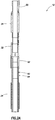
- FIGS. 2A-C an example of one longitudinal section of the completion string 12 is representatively illustrated.
- the illustrated section depicts how flow through the well screens 24 can be controlled effectively using the flow control devices 32.
- the section shown in FIGS. 2A-C may be used in the system 10 and completion string 12 of FIG. 1 , or it may be used in other systems and/or completion strings.
- FIGS. 2A-C three of the flow control devices 32 are used to variably restrict flow through six of the well screens 24. This demonstrates that any number of flow control devices 32 and any number of well screens 24 may be used to control flow of the fluid 52 between a corresponding one of the zones 28 and the completion string 12. The scope of this disclosure is not limited to any particular number or combination of the various components of the completion string 12.
- Another flow control device 54 may be used to selectively permit and prevent substantially unrestricted flow through the well screens 24.
- a mechanically actuated sliding sleeve-type valve, etc. may be used to selectively permit and prevent substantially unrestricted flow through the well screens 24.
- the flow control device 54 can be closed to thereby prevent flow through the screens 24, so that sufficient pressure can be applied external to the screens to force fluid outward into the corresponding zone 28.
- An upper one of the hydraulic control devices 34 is used to control operation of an upper one of the flow control devices 32 ( FIG. 2A ), and to control an intermediate one of the flow control devices ( FIG. 2B ).
- a lower one of the hydraulic control devices 34 is used to control actuation of a lower one of the flow control devices 32 ( FIG. 2C ).
- an inner tubular 60 is secured to an outer tubular 94 (for example, by means of threads, etc.), so that the inner tubular 60 can be used to support a weight of a remainder of the completion string 12 below.
- FIG. 3 an example of how the flow control device 32 can be used to control flow of the fluid 52 through the well screen 24 is representatively illustrated.
- the fluid 52 enters the well screen 24 and flows into an annular area 56 formed radially between a perforated base pipe 58 of the well screen and an inner tubular 60.
- the fluid 52 flows through the annular area 56 to the flow control device 32, which is contained within an outer tubular shroud 62.
- the flow control device 32 variably restricts the flow of the fluid 52 from the annular area 56 to a flow passage 64 extending longitudinally through the completion string 12.
- Such variable restriction may be used to balance production from the multiple zones 28, to prevent water or gas coning, etc.
- the variable restriction may be used to control a shape or extent of a water or steam flood front in the various zones, etc.
- FIG. 4 a manner in which the lines 50 may be routed through the completion string 12 is representatively illustrated.
- the shroud 62 is removed, so that the lines 50 extending from one of the flow control devices 32 (such as, the intermediate flow control device depicted in FIG. 2B ) to a well screen 24 below the flow control device may be seen.
- the lines 50 extend from a connector 66 on the flow control device 32 to an end connection 68 of the well screen 24, wherein the lines are routed to another connector 70 for extending the lines further down the completion string 12.
- the end connection 68 may be provided with flow passages (not shown) to allow the fluid 52 to flow longitudinally through the end connection from the well screen 24 to the flow control device 32 via the annular area 56. Casting the end connection 68 can allow for forming complex flow passage and conduit shapes in the end connection, but other means of fabricating the end connection may be used, if desired.
- the set 20 of completion equipment includes only one each of the well screen 24, flow control device 32, hydraulic control device 34 and flow control device 54.
- the set 20 of completion equipment includes only one each of the well screen 24, flow control device 32, hydraulic control device 34 and flow control device 54.
- any number or combination of components may be used, in keeping with the scope of this disclosure.
- FIG. 5 example One difference in the FIG. 5 example is that the flow control device 54 and at least a portion of the flow control device 32 are positioned within the well screen 24. This can provide a more longitudinally compact configuration, and eliminate use of the shroud 62. Thus, it will be appreciated that the scope of this disclosure is not limited to any particular configuration or arrangement of the components of the completion string 12.
- the hydraulic control device 34 can include the pressure sensor 36, which can be ported to the interior flow passage 64 and/or to the annulus 30 external to the completion string 12. Multiple pressure sensors 36 may be provided in the hydraulic control device 34 to separately sense pressures internal to, or external to, the completion string 12.
- the hydraulic control device 34 includes electronics 72 (such as, one or more processors, memory, batteries, etc.) responsive to signals transmitted from a remote location (for example, a control station at the earth's surface, a sea floor installation, a floating rig, etc.) via the lines 50 to direct hydraulic pressure (via a hydraulic manifold, not shown) to an actuator 74 of the flow control device 32.
- electronics 72 such as, one or more processors, memory, batteries, etc.
- the FIG. 6 flow control device 32 includes a sleeve 76 which is displaced by the actuator 74 relative to an opening 78 in an outer housing 80, in order to variably restrict flow through the opening.
- the flow control device 32 also includes a position indicator 82, so that the electronics 72 can verify whether the sleeve 76 is properly positioned to obtain a desired flow restriction.
- the pressure sensor (s) 36 may be used to verify that a desired pressure differential is achieved across the flow control device 32.
- a manner in which a wet connection 84 can be made between the lines 48 on the production string 38 and the lines 50 on the completion string 12 is representatively illustrated.
- the wet connection 84 is made above the uppermost packer 26, but in other examples the wet connection could be made within the packer, below the packer, or in another location.
- a wet connector 86 on the production string 38 is axially engaged with a wet connector 88 on the completion string 12 when the seals 40 are stabbed into the seal bore 42.
- the wet connection 84 preferably includes connectors 86, 88 for each of electrical, hydraulic and optical connections between the lines 48, 50.
- the lines 48 may be extended through the expansion joint 44 in the system 10 is representatively illustrated.
- the lines 48 preferably including electrical, hydraulic and optical lines
- the lines 48 are coiled between an inner mandrel 90 and an outer housing 92 of the expansion joint 44.
- expansion joint 44 is not necessary in the system 10.
- a spacing between the uppermost packer 26 and a tubing hanger seat in the wellhead (not shown) could be accurately measured, and the production string 38 could be configured correspondingly, in which case the packer 46 may not be used on the production string.
- flow control device 32 in the above examples is described as being a remotely hydraulically actuated variable choke, any type of flow control device which provides a variable resistance to flow may be used, in keeping with the scope of this disclosure.
- a remotely actuated inflow control device may be used.
- An inflow control device may be actuated using the hydraulic control device 34 described above, or relatively straightforward hydraulic control lines may be used to actuate an inflow control device.
- an autonomous inflow control device one which varies a resistance to flow without commands or actuation signals transmitted from a remote location
- an autonomous inflow control device such as those described in US Publication Nos. 2011/0042091 , 2011/0297385 , 2012/0048563 and others, may be used.
- an inflow control device (autonomous or remotely actuated) may be preferable for injection operations, for example, if precise regulation of flow resistance is not required.
- the scope of this disclosure is not limited to use of any particular type of flow control device, or use of a particular type of flow control device in a particular type of operation.
- a remotely operable sliding sleeve valve which opens on command from the surface could be utilized.
- An opening signal could be conveyed by electric control line, or the signal could be sent from the surface down the tubing, e.g., via HALSONICS(TM) pressure pulse telemetry, an ATS(TM) acoustic telemetry system, DYNALINK(TM) mud pulse telemetry system, an electromagnetic telemetry system, etc.
- the sliding sleeve valve could have a battery, a sensor, a computer (or at least a processor and memory), and an actuation system to open on command.
- separate pressure and/or temperature sensors may be conveyed into the completion string 12 during the method described above, in which characteristics and flow paths of the fluid 52 flowing between the completion string and the individual zones 28 are determined.
- a wireline or coiled tubing conveyed perforated dip tube could be conveyed into the completion string during or prior to performance of the method.
- a selectively variable flow control device 32 integrated with an optical sensor (e.g., an optical waveguide as part of the lines 50) external to the completion string 12, and pressure sensors 36 ported to an interior and/or exterior of the completion string.
- an optical sensor e.g., an optical waveguide as part of the lines 50
- the system 10 can include: multiple well screens 24 which filter fluid 52 flowing between a completion string 12 in the well and respective ones of the multiple zones 28; at least one optical waveguide 50 which senses at least one property of the fluid 52 as it flows between the completion string 12 and at least one of the zones 28; multiple flow control devices 32 which variably restrict flow of the fluid 52 through respective ones of the multiple well screens 24; and multiple pressure sensors 36 which sense pressure of the fluid 52 which flows through respective ones of the multiple well screens 24.
- the multiple well screens 24, the optical waveguide 50, the multiple flow control devices 32, and the multiple pressure sensors 36 can be installed in the well in a single trip into the well.
- the system 10 can also include multiple hydraulic control devices 34 which control application of hydraulic actuation pressure to respective ones of the multiple flow control devices 32.
- a single one of the hydraulic control devices 34 may control application of hydraulic actuation pressure to multiple ones of the flow control devices 32.
- the pressure sensors 36 may sense pressure of the fluid 52 external and/or internal to the completion string 12.
- the flow control devices 32 may comprise remotely hydraulically actuated variable chokes.
- the flow control devices 32 may comprise autonomous variable flow restrictors.
- the flow control devices 32 receive the fluid 52 from the respective ones of the multiple well screens 24.
- the system 10 may include a combined hydraulic, electrical and optical wet connection 84.
- the system 10 may include an expansion joint 44 with hydraulic, electrical and optical lines 48 traversing the expansion joint 44.
- the optical waveguide 50 can be positioned external to the well screens 24.
- the optical waveguide 50 can be positioned between the well screens 24 and the zones 28.
- the completion string 12 can include at least one well screen 24; at least one first flow control device 54; and at least one second flow control device 32, the second flow control device 32 being remotely operable.
- the first flow control device 54 selectively prevents and permits substantially unrestricted flow through the well screen 24.
- the second flow control device 32 variably restricts flow through the well screen 24.
- the completion string 12 can include a hydraulic control device 34 which controls application of hydraulic actuation pressure to the second flow control device 32.
- the second flow control device 32 may comprise multiple second flow control devices 32, and the hydraulic control device 34 may control application of hydraulic actuation pressure to the multiple second flow control devices 32.
- the completion string 12 can include at least one optical waveguide 50 which is operative to sense at least one property of a fluid 52 which flows through the well screen 24.
- the method can comprise: closing all of multiple flow control devices 32 connected in the completion string 12, the completion string 12 including multiple well screens 24 which filter fluid 52 flowing between the completion string 12 and respective ones of multiple earth formation zones 28, at least one optical waveguide 50 which senses at least one property of the fluid 52 as it flows between the completion string 12 and at least one of the zones 28, the multiple flow control devices 32 which variably restrict flow of the fluid 52 through respective ones of the multiple well screens 24, and multiple pressure sensors 36 which sense pressure of the fluid 52 which flows through respective ones of the multiple well screens 24; at least partially opening a first selected one of the flow control devices 32; and measuring a first change in the property sensed by the optical waveguide 50 and a first change in the pressure of the fluid 52 as a result of the opening of the first selected one of the flow control devices 32.
- the method can also include: closing all of the multiple flow control devices 32 after the step of at least partially opening the first selected one of the flow control devices 32; at least partially opening a second selected one of the flow control devices 32; and measuring a second change in the property sensed by the optical waveguide 50 and a second change in the pressure of the fluid 52 as a result of the opening of the second selected one of the flow control devices 32.
- the method can include installing the multiple well screens 24, the optical waveguide 50, the multiple flow control devices 32, and the multiple pressure sensors 36 in the well in a single trip into the well.
- the method can include closing all of the flow control devices 32, thereby preventing inadvertent flow of the fluid 52 into the completion string 12. This step can be useful in a well control situation.
- the method can include closing all of the flow control devices 32, thereby preventing inadvertent flow of the fluid 52 out of the completion string 12. This step can be useful in preventing loss of the fluid 52 to the surrounding zones 28.
Landscapes
- Geology (AREA)
- Life Sciences & Earth Sciences (AREA)
- Engineering & Computer Science (AREA)
- Mining & Mineral Resources (AREA)
- Physics & Mathematics (AREA)
- Geochemistry & Mineralogy (AREA)
- Fluid Mechanics (AREA)
- General Life Sciences & Earth Sciences (AREA)
- Environmental & Geological Engineering (AREA)
- Geophysics (AREA)
- Earth Drilling (AREA)
- Light Guides In General And Applications Therefor (AREA)
- Pipeline Systems (AREA)
- Bulkheads Adapted To Foundation Construction (AREA)
- Special Spraying Apparatus (AREA)
- Fluid-Pressure Circuits (AREA)
Claims (9)
- Colonne de complétion (12) destinée à être utilisée dans un puits souterrain (14), la colonne de complétion (12) comprenant :au moins un filtre de puits (24) ;un premier dispositif de commande d'écoulement (54) ; etau moins un second dispositif de commande d'écoulement (32) qui est actionnable séparément du premier dispositif de commande d'écoulement (54), le second dispositif de commande d'écoulement (32) pouvant fonctionner à distance,dans laquelle le premier dispositif de commande d'écoulement (54) empêche sélectivement et permet un écoulement sensiblement non restreint entre l'ensemble des filtres de puits (24) et un intérieur de la colonne de complétion (12) en même temps, et l'au moins un second dispositif de commande d'écoulement (32) restreint de manière variable l'écoulement entre un ou plusieurs des filtres de puits (24) et l'intérieur de la colonne de complétion (12).
- Colonne de complétion selon la revendication 1, comprenant en outre un dispositif de commande hydraulique (34) qui commande l'application d'une pression d'actionnement hydraulique à l'au moins un second dispositif de commande d'écoulement (32).
- Colonne de complétion selon la revendication 2, dans laquelle l'au moins un second dispositif de commande d'écoulement (32) comprend plusieurs seconds dispositifs de commande d'écoulement (32), et dans laquelle le dispositif de commande hydraulique (34) commande l'application d'une pression d'actionnement hydraulique à la pluralité de seconds dispositif de commande d'écoulement (32).
- Colonne de complétion selon la revendication 1, comprenant en outre au moins un guide d'onde optique (50) qui fonctionne de manière à détecter au moins une propriété d'un fluide (52) qui s'écoule à travers le filtre de puits (24).
- Colonne de complétion selon la revendication 4, dans laquelle le guide d'onde optique (50) est positionné à l'extérieur du filtre de puits (24).
- Colonne de complétion selon la revendication 4, dans laquelle le guide d'onde optique (50) est positionné entre le filtre de puits (24) et une formation terrestre (28).
- Colonne de complétion selon la revendication 1, dans laquelle le second dispositif de commande d'écoulement (32) comprend un étranglement variable actionné hydrauliquement.
- Colonne de complétion selon la revendication 1, comprenant en outre un capteur de pression (36) qui détecte la pression à l'extérieur de la colonne de complétion (12).
- Colonne de complétion selon la revendication 1, comprenant en outre un capteur de pression (36) qui détecte la pression à l'intérieur de la colonne de complétion (12).
Priority Applications (1)
| Application Number | Priority Date | Filing Date | Title |
|---|---|---|---|
| EP19187957.6A EP3578752B1 (fr) | 2012-09-26 | 2012-09-26 | Système intelligent et intégré de complétion de puits présentant plusieurs zones |
Applications Claiming Priority (3)
| Application Number | Priority Date | Filing Date | Title |
|---|---|---|---|
| EP12885563.2A EP2900903B1 (fr) | 2012-09-26 | 2012-09-26 | Système intelligent et intégré de complétion de puits présentant plusieurs zones |
| PCT/US2012/057215 WO2014051557A1 (fr) | 2012-09-26 | 2012-09-26 | Système intelligent et intégré de complétion de puits présentant plusieurs zones |
| EP19187957.6A EP3578752B1 (fr) | 2012-09-26 | 2012-09-26 | Système intelligent et intégré de complétion de puits présentant plusieurs zones |
Related Parent Applications (2)
| Application Number | Title | Priority Date | Filing Date |
|---|---|---|---|
| EP12885563.2A Division-Into EP2900903B1 (fr) | 2012-09-26 | 2012-09-26 | Système intelligent et intégré de complétion de puits présentant plusieurs zones |
| EP12885563.2A Division EP2900903B1 (fr) | 2012-09-26 | 2012-09-26 | Système intelligent et intégré de complétion de puits présentant plusieurs zones |
Publications (2)
| Publication Number | Publication Date |
|---|---|
| EP3578752A1 EP3578752A1 (fr) | 2019-12-11 |
| EP3578752B1 true EP3578752B1 (fr) | 2020-12-23 |
Family
ID=50388764
Family Applications (2)
| Application Number | Title | Priority Date | Filing Date |
|---|---|---|---|
| EP19187957.6A Active EP3578752B1 (fr) | 2012-09-26 | 2012-09-26 | Système intelligent et intégré de complétion de puits présentant plusieurs zones |
| EP12885563.2A Active EP2900903B1 (fr) | 2012-09-26 | 2012-09-26 | Système intelligent et intégré de complétion de puits présentant plusieurs zones |
Family Applications After (1)
| Application Number | Title | Priority Date | Filing Date |
|---|---|---|---|
| EP12885563.2A Active EP2900903B1 (fr) | 2012-09-26 | 2012-09-26 | Système intelligent et intégré de complétion de puits présentant plusieurs zones |
Country Status (6)
| Country | Link |
|---|---|
| EP (2) | EP3578752B1 (fr) |
| AU (2) | AU2012391052B2 (fr) |
| BR (2) | BR112015006645B1 (fr) |
| MX (1) | MX355034B (fr) |
| SG (1) | SG11201502303UA (fr) |
| WO (1) | WO2014051557A1 (fr) |
Cited By (1)
| Publication number | Priority date | Publication date | Assignee | Title |
|---|---|---|---|---|
| WO2024209196A1 (fr) * | 2023-04-06 | 2024-10-10 | Metrol Technology Limited | Ensembles de gestion d'écoulement, procédés et puits |
Family Cites Families (15)
| Publication number | Priority date | Publication date | Assignee | Title |
|---|---|---|---|---|
| US4949788A (en) * | 1989-11-08 | 1990-08-21 | Halliburton Company | Well completions using casing valves |
| CA2264632C (fr) * | 1997-05-02 | 2007-11-27 | Baker Hughes Incorporated | Puits utilisant des detecteurs et des equipements operationnels a base de fibres optiques |
| US6478091B1 (en) * | 2000-05-04 | 2002-11-12 | Halliburton Energy Services, Inc. | Expandable liner and associated methods of regulating fluid flow in a well |
| AU2001212268A1 (en) * | 2000-10-23 | 2002-05-06 | Halliburton Energy Services, Inc. | Fluid property sensors and associated methods of calibrating sensors in a subterranean well |
| US7222676B2 (en) * | 2000-12-07 | 2007-05-29 | Schlumberger Technology Corporation | Well communication system |
| AU2004225541B2 (en) * | 2003-03-28 | 2008-03-13 | Shell Internationale Research Maatschappij B.V. | Surface flow controlled valve and screen |
| US7428924B2 (en) * | 2004-12-23 | 2008-09-30 | Schlumberger Technology Corporation | System and method for completing a subterranean well |
| US7857061B2 (en) * | 2008-05-20 | 2010-12-28 | Halliburton Energy Services, Inc. | Flow control in a well bore |
| US7814973B2 (en) * | 2008-08-29 | 2010-10-19 | Halliburton Energy Services, Inc. | Sand control screen assembly and method for use of same |
| US8196653B2 (en) * | 2009-04-07 | 2012-06-12 | Halliburton Energy Services, Inc. | Well screens constructed utilizing pre-formed annular elements |
| US8276669B2 (en) | 2010-06-02 | 2012-10-02 | Halliburton Energy Services, Inc. | Variable flow resistance system with circulation inducing structure therein to variably resist flow in a subterranean well |
| US8235128B2 (en) | 2009-08-18 | 2012-08-07 | Halliburton Energy Services, Inc. | Flow path control based on fluid characteristics to thereby variably resist flow in a subterranean well |
| US8925631B2 (en) * | 2010-03-04 | 2015-01-06 | Schlumberger Technology Corporation | Large bore completions systems and method |
| US8356668B2 (en) | 2010-08-27 | 2013-01-22 | Halliburton Energy Services, Inc. | Variable flow restrictor for use in a subterranean well |
| US8776897B2 (en) * | 2011-01-03 | 2014-07-15 | Schlumberger Technology Corporation | Method and apparatus for multi-drop tool control |
-
2012
- 2012-09-26 EP EP19187957.6A patent/EP3578752B1/fr active Active
- 2012-09-26 BR BR112015006645-3A patent/BR112015006645B1/pt active IP Right Grant
- 2012-09-26 MX MX2015003815A patent/MX355034B/es active IP Right Grant
- 2012-09-26 WO PCT/US2012/057215 patent/WO2014051557A1/fr not_active Ceased
- 2012-09-26 EP EP12885563.2A patent/EP2900903B1/fr active Active
- 2012-09-26 SG SG11201502303UA patent/SG11201502303UA/en unknown
- 2012-09-26 AU AU2012391052A patent/AU2012391052B2/en active Active
- 2012-09-26 BR BR122020004840-9A patent/BR122020004840B1/pt active IP Right Grant
-
2016
- 2016-09-13 AU AU2016228178A patent/AU2016228178B2/en active Active
Non-Patent Citations (1)
| Title |
|---|
| None * |
Cited By (1)
| Publication number | Priority date | Publication date | Assignee | Title |
|---|---|---|---|---|
| WO2024209196A1 (fr) * | 2023-04-06 | 2024-10-10 | Metrol Technology Limited | Ensembles de gestion d'écoulement, procédés et puits |
Also Published As
| Publication number | Publication date |
|---|---|
| MX355034B (es) | 2018-04-02 |
| AU2016228178B2 (en) | 2017-12-14 |
| MX2015003815A (es) | 2015-07-14 |
| BR112015006645B1 (pt) | 2020-12-01 |
| EP2900903A4 (fr) | 2016-11-16 |
| AU2016228178A1 (en) | 2016-09-29 |
| EP2900903B1 (fr) | 2019-09-04 |
| AU2012391052A1 (en) | 2015-04-02 |
| BR112015006645A2 (pt) | 2017-07-04 |
| SG11201502303UA (en) | 2015-04-29 |
| WO2014051557A1 (fr) | 2014-04-03 |
| AU2012391052B2 (en) | 2016-06-23 |
| EP2900903A1 (fr) | 2015-08-05 |
| EP3578752A1 (fr) | 2019-12-11 |
| BR122020004840B1 (pt) | 2021-05-04 |
Similar Documents
| Publication | Publication Date | Title |
|---|---|---|
| US9428999B2 (en) | Multiple zone integrated intelligent well completion | |
| US8893783B2 (en) | Tubing conveyed multiple zone integrated intelligent well completion | |
| EP2673460B1 (fr) | Ensemble de complétion | |
| US8746337B2 (en) | Single trip multi-zone completion systems and methods | |
| EP2900908B1 (fr) | Systèmes et procédés de complétion présentant plusieurs zones et à manoevre unique | |
| US20020074119A1 (en) | Thru-tubing sand control method and apparatus | |
| US8985215B2 (en) | Single trip multi-zone completion systems and methods | |
| US20030079878A1 (en) | Completion system, apparatus, and method | |
| AU2016228178B2 (en) | Multiple zone integrated intelligent well completion | |
| EP2900905B1 (fr) | Système intelligent et intégré de complétion de puits présentant plusieurs zones et acheminé par tubages | |
| OA16528A (en) | Completion assembly. |
Legal Events
| Date | Code | Title | Description |
|---|---|---|---|
| PUAI | Public reference made under article 153(3) epc to a published international application that has entered the european phase |
Free format text: ORIGINAL CODE: 0009012 |
|
| STAA | Information on the status of an ep patent application or granted ep patent |
Free format text: STATUS: REQUEST FOR EXAMINATION WAS MADE |
|
| 17P | Request for examination filed |
Effective date: 20190723 |
|
| AC | Divisional application: reference to earlier application |
Ref document number: 2900903 Country of ref document: EP Kind code of ref document: P |
|
| AK | Designated contracting states |
Kind code of ref document: A1 Designated state(s): AL AT BE BG CH CY CZ DE DK EE ES FI FR GB GR HR HU IE IS IT LI LT LU LV MC MK MT NL NO PL PT RO RS SE SI SK SM TR |
|
| RIN1 | Information on inventor provided before grant (corrected) |
Inventor name: RICHARD, WILLIAM Inventor name: TIPS, TIMOTHY |
|
| RBV | Designated contracting states (corrected) |
Designated state(s): AL AT BE BG CH CY CZ DE DK EE ES FI FR GB GR HR HU IE IS IT LI LT LU LV MC MK MT NL NO PL PT RO RS SE SI SK SM TR |
|
| GRAP | Despatch of communication of intention to grant a patent |
Free format text: ORIGINAL CODE: EPIDOSNIGR1 |
|
| STAA | Information on the status of an ep patent application or granted ep patent |
Free format text: STATUS: GRANT OF PATENT IS INTENDED |
|
| INTG | Intention to grant announced |
Effective date: 20200731 |
|
| RIC1 | Information provided on ipc code assigned before grant |
Ipc: E21B 43/12 20060101AFI20200721BHEP Ipc: E21B 47/06 20120101ALI20200721BHEP Ipc: E21B 47/113 20120101ALI20200721BHEP Ipc: E21B 43/14 20060101ALI20200721BHEP |
|
| GRAS | Grant fee paid |
Free format text: ORIGINAL CODE: EPIDOSNIGR3 |
|
| GRAA | (expected) grant |
Free format text: ORIGINAL CODE: 0009210 |
|
| STAA | Information on the status of an ep patent application or granted ep patent |
Free format text: STATUS: THE PATENT HAS BEEN GRANTED |
|
| AC | Divisional application: reference to earlier application |
Ref document number: 2900903 Country of ref document: EP Kind code of ref document: P |
|
| AK | Designated contracting states |
Kind code of ref document: B1 Designated state(s): AL AT BE BG CH CY CZ DE DK EE ES FI FR GB GR HR HU IE IS IT LI LT LU LV MC MK MT NL NO PL PT RO RS SE SI SK SM TR |
|
| REG | Reference to a national code |
Ref country code: GB Ref legal event code: FG4D |
|
| REG | Reference to a national code |
Ref country code: DE Ref legal event code: R096 Ref document number: 602012073909 Country of ref document: DE |
|
| REG | Reference to a national code |
Ref country code: AT Ref legal event code: REF Ref document number: 1347899 Country of ref document: AT Kind code of ref document: T Effective date: 20210115 |
|
| REG | Reference to a national code |
Ref country code: IE Ref legal event code: FG4D |
|
| PG25 | Lapsed in a contracting state [announced via postgrant information from national office to epo] |
Ref country code: FI Free format text: LAPSE BECAUSE OF FAILURE TO SUBMIT A TRANSLATION OF THE DESCRIPTION OR TO PAY THE FEE WITHIN THE PRESCRIBED TIME-LIMIT Effective date: 20201223 Ref country code: RS Free format text: LAPSE BECAUSE OF FAILURE TO SUBMIT A TRANSLATION OF THE DESCRIPTION OR TO PAY THE FEE WITHIN THE PRESCRIBED TIME-LIMIT Effective date: 20201223 Ref country code: NO Free format text: LAPSE BECAUSE OF FAILURE TO SUBMIT A TRANSLATION OF THE DESCRIPTION OR TO PAY THE FEE WITHIN THE PRESCRIBED TIME-LIMIT Effective date: 20210323 Ref country code: GR Free format text: LAPSE BECAUSE OF FAILURE TO SUBMIT A TRANSLATION OF THE DESCRIPTION OR TO PAY THE FEE WITHIN THE PRESCRIBED TIME-LIMIT Effective date: 20210324 |
|
| REG | Reference to a national code |
Ref country code: AT Ref legal event code: MK05 Ref document number: 1347899 Country of ref document: AT Kind code of ref document: T Effective date: 20201223 |
|
| REG | Reference to a national code |
Ref country code: NL Ref legal event code: MP Effective date: 20201223 |
|
| PG25 | Lapsed in a contracting state [announced via postgrant information from national office to epo] |
Ref country code: BG Free format text: LAPSE BECAUSE OF FAILURE TO SUBMIT A TRANSLATION OF THE DESCRIPTION OR TO PAY THE FEE WITHIN THE PRESCRIBED TIME-LIMIT Effective date: 20210323 Ref country code: SE Free format text: LAPSE BECAUSE OF FAILURE TO SUBMIT A TRANSLATION OF THE DESCRIPTION OR TO PAY THE FEE WITHIN THE PRESCRIBED TIME-LIMIT Effective date: 20201223 Ref country code: LV Free format text: LAPSE BECAUSE OF FAILURE TO SUBMIT A TRANSLATION OF THE DESCRIPTION OR TO PAY THE FEE WITHIN THE PRESCRIBED TIME-LIMIT Effective date: 20201223 |
|
| PG25 | Lapsed in a contracting state [announced via postgrant information from national office to epo] |
Ref country code: NL Free format text: LAPSE BECAUSE OF FAILURE TO SUBMIT A TRANSLATION OF THE DESCRIPTION OR TO PAY THE FEE WITHIN THE PRESCRIBED TIME-LIMIT Effective date: 20201223 Ref country code: HR Free format text: LAPSE BECAUSE OF FAILURE TO SUBMIT A TRANSLATION OF THE DESCRIPTION OR TO PAY THE FEE WITHIN THE PRESCRIBED TIME-LIMIT Effective date: 20201223 |
|
| REG | Reference to a national code |
Ref country code: LT Ref legal event code: MG9D |
|
| PG25 | Lapsed in a contracting state [announced via postgrant information from national office to epo] |
Ref country code: CZ Free format text: LAPSE BECAUSE OF FAILURE TO SUBMIT A TRANSLATION OF THE DESCRIPTION OR TO PAY THE FEE WITHIN THE PRESCRIBED TIME-LIMIT Effective date: 20201223 Ref country code: SK Free format text: LAPSE BECAUSE OF FAILURE TO SUBMIT A TRANSLATION OF THE DESCRIPTION OR TO PAY THE FEE WITHIN THE PRESCRIBED TIME-LIMIT Effective date: 20201223 Ref country code: SM Free format text: LAPSE BECAUSE OF FAILURE TO SUBMIT A TRANSLATION OF THE DESCRIPTION OR TO PAY THE FEE WITHIN THE PRESCRIBED TIME-LIMIT Effective date: 20201223 Ref country code: EE Free format text: LAPSE BECAUSE OF FAILURE TO SUBMIT A TRANSLATION OF THE DESCRIPTION OR TO PAY THE FEE WITHIN THE PRESCRIBED TIME-LIMIT Effective date: 20201223 Ref country code: RO Free format text: LAPSE BECAUSE OF FAILURE TO SUBMIT A TRANSLATION OF THE DESCRIPTION OR TO PAY THE FEE WITHIN THE PRESCRIBED TIME-LIMIT Effective date: 20201223 Ref country code: PT Free format text: LAPSE BECAUSE OF FAILURE TO SUBMIT A TRANSLATION OF THE DESCRIPTION OR TO PAY THE FEE WITHIN THE PRESCRIBED TIME-LIMIT Effective date: 20210423 Ref country code: LT Free format text: LAPSE BECAUSE OF FAILURE TO SUBMIT A TRANSLATION OF THE DESCRIPTION OR TO PAY THE FEE WITHIN THE PRESCRIBED TIME-LIMIT Effective date: 20201223 |
|
| PG25 | Lapsed in a contracting state [announced via postgrant information from national office to epo] |
Ref country code: AT Free format text: LAPSE BECAUSE OF FAILURE TO SUBMIT A TRANSLATION OF THE DESCRIPTION OR TO PAY THE FEE WITHIN THE PRESCRIBED TIME-LIMIT Effective date: 20201223 Ref country code: PL Free format text: LAPSE BECAUSE OF FAILURE TO SUBMIT A TRANSLATION OF THE DESCRIPTION OR TO PAY THE FEE WITHIN THE PRESCRIBED TIME-LIMIT Effective date: 20201223 |
|
| REG | Reference to a national code |
Ref country code: DE Ref legal event code: R097 Ref document number: 602012073909 Country of ref document: DE |
|
| PG25 | Lapsed in a contracting state [announced via postgrant information from national office to epo] |
Ref country code: IS Free format text: LAPSE BECAUSE OF FAILURE TO SUBMIT A TRANSLATION OF THE DESCRIPTION OR TO PAY THE FEE WITHIN THE PRESCRIBED TIME-LIMIT Effective date: 20210423 |
|
| PG25 | Lapsed in a contracting state [announced via postgrant information from national office to epo] |
Ref country code: IT Free format text: LAPSE BECAUSE OF FAILURE TO SUBMIT A TRANSLATION OF THE DESCRIPTION OR TO PAY THE FEE WITHIN THE PRESCRIBED TIME-LIMIT Effective date: 20201223 Ref country code: AL Free format text: LAPSE BECAUSE OF FAILURE TO SUBMIT A TRANSLATION OF THE DESCRIPTION OR TO PAY THE FEE WITHIN THE PRESCRIBED TIME-LIMIT Effective date: 20201223 |
|
| PLBE | No opposition filed within time limit |
Free format text: ORIGINAL CODE: 0009261 |
|
| STAA | Information on the status of an ep patent application or granted ep patent |
Free format text: STATUS: NO OPPOSITION FILED WITHIN TIME LIMIT |
|
| PG25 | Lapsed in a contracting state [announced via postgrant information from national office to epo] |
Ref country code: DK Free format text: LAPSE BECAUSE OF FAILURE TO SUBMIT A TRANSLATION OF THE DESCRIPTION OR TO PAY THE FEE WITHIN THE PRESCRIBED TIME-LIMIT Effective date: 20201223 |
|
| 26N | No opposition filed |
Effective date: 20210924 |
|
| PG25 | Lapsed in a contracting state [announced via postgrant information from national office to epo] |
Ref country code: ES Free format text: LAPSE BECAUSE OF FAILURE TO SUBMIT A TRANSLATION OF THE DESCRIPTION OR TO PAY THE FEE WITHIN THE PRESCRIBED TIME-LIMIT Effective date: 20201223 |
|
| PG25 | Lapsed in a contracting state [announced via postgrant information from national office to epo] |
Ref country code: SI Free format text: LAPSE BECAUSE OF FAILURE TO SUBMIT A TRANSLATION OF THE DESCRIPTION OR TO PAY THE FEE WITHIN THE PRESCRIBED TIME-LIMIT Effective date: 20201223 |
|
| REG | Reference to a national code |
Ref country code: DE Ref legal event code: R119 Ref document number: 602012073909 Country of ref document: DE |
|
| REG | Reference to a national code |
Ref country code: CH Ref legal event code: PL |
|
| REG | Reference to a national code |
Ref country code: BE Ref legal event code: MM Effective date: 20210930 |
|
| PG25 | Lapsed in a contracting state [announced via postgrant information from national office to epo] |
Ref country code: IS Free format text: LAPSE BECAUSE OF FAILURE TO SUBMIT A TRANSLATION OF THE DESCRIPTION OR TO PAY THE FEE WITHIN THE PRESCRIBED TIME-LIMIT Effective date: 20210423 Ref country code: MC Free format text: LAPSE BECAUSE OF FAILURE TO SUBMIT A TRANSLATION OF THE DESCRIPTION OR TO PAY THE FEE WITHIN THE PRESCRIBED TIME-LIMIT Effective date: 20201223 |
|
| PG25 | Lapsed in a contracting state [announced via postgrant information from national office to epo] |
Ref country code: LU Free format text: LAPSE BECAUSE OF NON-PAYMENT OF DUE FEES Effective date: 20210926 Ref country code: IE Free format text: LAPSE BECAUSE OF NON-PAYMENT OF DUE FEES Effective date: 20210926 Ref country code: FR Free format text: LAPSE BECAUSE OF NON-PAYMENT OF DUE FEES Effective date: 20210930 Ref country code: DE Free format text: LAPSE BECAUSE OF NON-PAYMENT OF DUE FEES Effective date: 20220401 Ref country code: BE Free format text: LAPSE BECAUSE OF NON-PAYMENT OF DUE FEES Effective date: 20210930 |
|
| PG25 | Lapsed in a contracting state [announced via postgrant information from national office to epo] |
Ref country code: LI Free format text: LAPSE BECAUSE OF NON-PAYMENT OF DUE FEES Effective date: 20210930 Ref country code: CH Free format text: LAPSE BECAUSE OF NON-PAYMENT OF DUE FEES Effective date: 20210930 |
|
| PG25 | Lapsed in a contracting state [announced via postgrant information from national office to epo] |
Ref country code: CY Free format text: LAPSE BECAUSE OF FAILURE TO SUBMIT A TRANSLATION OF THE DESCRIPTION OR TO PAY THE FEE WITHIN THE PRESCRIBED TIME-LIMIT Effective date: 20201223 |
|
| PG25 | Lapsed in a contracting state [announced via postgrant information from national office to epo] |
Ref country code: HU Free format text: LAPSE BECAUSE OF FAILURE TO SUBMIT A TRANSLATION OF THE DESCRIPTION OR TO PAY THE FEE WITHIN THE PRESCRIBED TIME-LIMIT; INVALID AB INITIO Effective date: 20120926 |
|
| PG25 | Lapsed in a contracting state [announced via postgrant information from national office to epo] |
Ref country code: MK Free format text: LAPSE BECAUSE OF FAILURE TO SUBMIT A TRANSLATION OF THE DESCRIPTION OR TO PAY THE FEE WITHIN THE PRESCRIBED TIME-LIMIT Effective date: 20201223 |
|
| PG25 | Lapsed in a contracting state [announced via postgrant information from national office to epo] |
Ref country code: MT Free format text: LAPSE BECAUSE OF FAILURE TO SUBMIT A TRANSLATION OF THE DESCRIPTION OR TO PAY THE FEE WITHIN THE PRESCRIBED TIME-LIMIT Effective date: 20201223 |
|
| PGFP | Annual fee paid to national office [announced via postgrant information from national office to epo] |
Ref country code: GB Payment date: 20250701 Year of fee payment: 14 |
|
| PG25 | Lapsed in a contracting state [announced via postgrant information from national office to epo] |
Ref country code: TR Free format text: LAPSE BECAUSE OF FAILURE TO SUBMIT A TRANSLATION OF THE DESCRIPTION OR TO PAY THE FEE WITHIN THE PRESCRIBED TIME-LIMIT Effective date: 20201223 |