EP3578802A1 - Hochdruckbrennstoffförderpumpe - Google Patents
Hochdruckbrennstoffförderpumpe Download PDFInfo
- Publication number
- EP3578802A1 EP3578802A1 EP18747466.3A EP18747466A EP3578802A1 EP 3578802 A1 EP3578802 A1 EP 3578802A1 EP 18747466 A EP18747466 A EP 18747466A EP 3578802 A1 EP3578802 A1 EP 3578802A1
- Authority
- EP
- European Patent Office
- Prior art keywords
- high pressure
- functional component
- welded portion
- fuel
- fuel supply
- Prior art date
- Legal status (The legal status is an assumption and is not a legal conclusion. Google has not performed a legal analysis and makes no representation as to the accuracy of the status listed.)
- Granted
Links
Images



Classifications
-
- F—MECHANICAL ENGINEERING; LIGHTING; HEATING; WEAPONS; BLASTING
- F02—COMBUSTION ENGINES; HOT-GAS OR COMBUSTION-PRODUCT ENGINE PLANTS
- F02M—SUPPLYING COMBUSTION ENGINES IN GENERAL WITH COMBUSTIBLE MIXTURES OR CONSTITUENTS THEREOF
- F02M59/00—Pumps specially adapted for fuel-injection and not provided for in groups F02M39/00 -F02M57/00, e.g. rotary cylinder-block type of pumps
- F02M59/44—Details, components parts, or accessories not provided for in, or of interest apart from, the apparatus of groups F02M59/02 - F02M59/42; Pumps having transducers, e.g. to measure displacement of pump rack or piston
- F02M59/48—Assembling; Disassembling; Replacing
-
- B—PERFORMING OPERATIONS; TRANSPORTING
- B23—MACHINE TOOLS; METAL-WORKING NOT OTHERWISE PROVIDED FOR
- B23K—SOLDERING OR UNSOLDERING; WELDING; CLADDING OR PLATING BY SOLDERING OR WELDING; CUTTING BY APPLYING HEAT LOCALLY, e.g. FLAME CUTTING; WORKING BY LASER BEAM
- B23K26/00—Working by laser beam, e.g. welding, cutting or boring
- B23K26/20—Bonding
- B23K26/21—Bonding by welding
-
- B—PERFORMING OPERATIONS; TRANSPORTING
- B23—MACHINE TOOLS; METAL-WORKING NOT OTHERWISE PROVIDED FOR
- B23K—SOLDERING OR UNSOLDERING; WELDING; CLADDING OR PLATING BY SOLDERING OR WELDING; CUTTING BY APPLYING HEAT LOCALLY, e.g. FLAME CUTTING; WORKING BY LASER BEAM
- B23K26/00—Working by laser beam, e.g. welding, cutting or boring
- B23K26/20—Bonding
- B23K26/21—Bonding by welding
- B23K26/24—Seam welding
- B23K26/28—Seam welding of curved planar seams
-
- F—MECHANICAL ENGINEERING; LIGHTING; HEATING; WEAPONS; BLASTING
- F02—COMBUSTION ENGINES; HOT-GAS OR COMBUSTION-PRODUCT ENGINE PLANTS
- F02M—SUPPLYING COMBUSTION ENGINES IN GENERAL WITH COMBUSTIBLE MIXTURES OR CONSTITUENTS THEREOF
- F02M59/00—Pumps specially adapted for fuel-injection and not provided for in groups F02M39/00 -F02M57/00, e.g. rotary cylinder-block type of pumps
- F02M59/44—Details, components parts, or accessories not provided for in, or of interest apart from, the apparatus of groups F02M59/02 - F02M59/42; Pumps having transducers, e.g. to measure displacement of pump rack or piston
- F02M59/46—Valves
-
- F—MECHANICAL ENGINEERING; LIGHTING; HEATING; WEAPONS; BLASTING
- F02—COMBUSTION ENGINES; HOT-GAS OR COMBUSTION-PRODUCT ENGINE PLANTS
- F02M—SUPPLYING COMBUSTION ENGINES IN GENERAL WITH COMBUSTIBLE MIXTURES OR CONSTITUENTS THEREOF
- F02M2200/00—Details of fuel-injection apparatus, not otherwise provided for
- F02M2200/80—Fuel injection apparatus manufacture, repair or assembly
- F02M2200/8084—Fuel injection apparatus manufacture, repair or assembly involving welding or soldering
Definitions
- the present invention relates to a high pressure fuel supply pump for pumping fuel to a fuel injection valve of an internal combustion engine.
- PTL 1 discloses that "welding is performed by butting a joining end surface 50 of a cup member 12a and a joining end surface 51 of a shaft member 13a and irradiating the abutting portion with a high energy density beam radially from the outside of the cup member 12a" (see paragraph 0041).
- joining is performed by irradiating the abutting portion between the cup member and the shaft member with a high energy density beam such as laser welding or electron beam welding radially from the outside.
- a high energy density beam such as laser welding or electron beam welding radially from the outside.
- the product and the high energy density beam interfere with each other to make joining difficult. In that case, it is necessary to adjust the irradiation angle of the laser. However, due to the characteristics of laser welding, the irradiation angle of the laser with respect to the irradiation surface of the laser is limited.
- an object of the present invention is to provide a high pressure fuel supply pump in which a functional component can be fixed by welding, while the freedom degree of arrangement of the functional component is improved.
- a high pressure fuel supply pump is characterized by “including: a pump body; a functional component attached to the pump body; a welded portion that fixes the functional component to the pump body; and an air gap formed by the welded portion, the pump body, and the functional component at a tip of a welding direction of the welded portion, in which a straight line connecting a middle of an entrance surface in the welding direction of the welded portion and a middle of an exit surface forming the air gap is formed so as to head from a radially outside to a radially inside of the functional component as heading toward an attachment direction in an axis direction of the functional component".
- a high pressure fuel supply pump can be provided, in which a functional component can be fixed by welding, while the freedom degree of arrangement of the functional component is improved.
- FIG. 8 is a configuration diagram of an engine system to which a high pressure fuel supply pump (hereinafter, referred to as a high pressure pump) according to a first embodiment of the present invention is applied.
- a high pressure fuel supply pump hereinafter, referred to as a high pressure pump
- the portion enclosed by a broken line shows a pump body 1 of the high pressure pump, and the mechanisms and components shown in the broken line indicates that they are integrally incorporated into the pump body 1 of the high pressure pump.
- the fuel in a fuel tank 20 is pumped up by a feed pump 21 on the basis of a signal from an engine control unit 27 (hereinafter, referred to as an ECU).
- the fuel is pressurized to an appropriate feed pressure and sent through a suction piping 28 to a low pressure fuel suction port 10a of the high pressure pump.
- the fuel that has passed through a suction joint 51 from the low pressure fuel suction port 10a reaches a suction port 31b of an electromagnetic suction valve mechanism 300 that constitutes a capacity variable mechanism through a pressure pulsation reduction mechanism 9 and a suction passage 10d.
- the fuel flowing into the electromagnetic suction valve mechanism 300 passes through a suction valve 30 and flows into a pressure chamber 11.
- a cam mechanism 93 of an engine gives power to the plunger 2 to reciprocate. Due to the reciprocating motion of a plunger 2, fuel is sucked from the suction valve 30 in the descending stroke of the plunger 2, and the fuel is pressurized in the ascending stroke.
- the fuel is pumped through a discharge valve mechanism 8 to a common rail 23 on which a pressure sensor 26 is mounted.
- An injector 24 injects fuel to the engine on the basis of the signal from the ECU 27.
- the high pressure pump discharges the fuel flow rate of the desired supply fuel according to a signal from the ECU 27 to the electromagnetic suction valve mechanism 300.
- the necessary amount of fuel introduced to the suction joint 51 is pressurized to a high pressure by the reciprocation of the plunger 2 in the pressure chamber 11 of the pump body 1 and is pumped from a fuel discharge port 12c to the common rail 23.
- An injector 24 for direct injection (so-called direct injector) and a pressure sensor 26 are mounted on the common rail 23.
- the direct injector 24 is mounted in accordance with the number of cylinders of the internal combustion engine, opens and closes the valve in accordance with the control signal of the ECU 27, and injects the fuel into the cylinder.
- the present embodiment is a high pressure pump applied to a so-called direct injection engine system in which the injector 24 injects fuel directly into the cylinder of the engine.
- FIG. 1 is a longitudinal sectional view of a high pressure pump according to the present embodiment
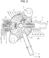
- FIG. 2 is a horizontal sectional view of the high pressure pump as viewed from above.
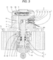
- FIG. 3 is a longitudinal sectional view of the high pressure pump as viewed from a different direction from that of FIG. 1 .
- FIG. 9 is a longitudinal sectional view of the high pressure pump in which the suction joint 51 is attached to a side surface of the pump body 1.
- suction joint 51 is provided on the side surface of the body in FIG. 2
- the present invention is not limited to this, and can be applied to a high pressure pump having the suction joint 51 provided on the upper surface of a damper cover 14.
- the high pressure pump of the present embodiment will be described with reference to FIGS. 1 , 2 , and 3 .
- the fuel flowing from the low pressure fuel suction port 10a of the suction joint 51 flows through the low pressure flow path formed inside the pump body 1 to a damper chamber formed in a damper upper portion 10b and a damper lower portion 10c.
- the damper chamber is formed by being covered by the damper cover 14 attached to the pump body 1.
- the fuel whose pressure pulsation is reduced by the pressure pulsation reduction mechanism 9 in the damper chamber reaches the suction port 31b of the electromagnetic suction valve 300 via the low pressure fuel passage 10d.
- the high pressure pump of the present embodiment is made to be in close contact with a flat surface of a cylinder head 90 of an internal combustion engine using a mounting flange 1e provided on the pump body 1 and is fixed by a plurality of bolts not shown.
- An O-ring 61 is fitted into the pump body 1 for sealing between the cylinder head 90 and the pump body 1 to prevent engine oil from leaking to the outside.
- a cylinder 6 is attached to the pump body 1 for guiding the reciprocating motion of the plunger 2. Furthermore, the electromagnetic suction valve 300 for supplying the fuel to the pressure chamber 11 via a pressure chamber inlet flow path 1a formed in the pump body 1, and a discharge valve mechanism 8 for discharging the fuel from the pressure chamber 11 to the discharge passage to prevent back flow are provided.
- the fuel that has passed through the discharge valve mechanism 8 is connected to an engine-side component by a discharge joint 12c.
- the cylinder 6 is fixed to the pump body 1 by press fitting and caulking on the outer circumferential side thereof. Sealing is performed with the surface of a cylindrical press-fit portion such that the pressurized fuel does not leak from the gap with the pump body 1 to the low pressure side.
- the cylinder is brought into axial contact with a plane, and functions also as a double sealing in addition to the sealing of cylindrical press-fit portion of and the pump body 1 and the cylinder 6.
- a tappet 92 for converting rotational motion of a cam 93 attached to the camshaft of the internal combustion engine into vertical motion and transmitting the motion to the plunger 2.
- the plunger 2 is pressed against the tappet 92 by a spring 4 through a retainer 15. As a result, the plunger 2 can be reciprocated vertically with the rotational motion of the cam 93.
- a plunger seal 13 held at the lower end portion of the inner circumference of a seal holder 7 is installed in a slidable contact with the outer circumference of the plunger 2 at the lower portion in the drawing of the cylinder 6.
- the plunger seal 13 seals the fuel in an auxiliary chamber 7a and prevents the fuel from flowing into the internal combustion engine.
- the plunger seal 13 prevents lubricating oil (including engine oil) lubricating a sliding portion in the internal combustion engine from flowing into the pump body 1.
- the suction joint 51 is attached to the pump body 1.
- the suction joint 51 is connected to a low pressure piping that supplies fuel from the fuel tank 20 of the vehicle, and the fuel is supplied from the connected position to the inside of the high pressure pump.
- the suction filter 52 pressed into the pump body 1 has a function of preventing foreign matter present between the fuel tank 20 and the low pressure fuel suction port 10a from being absorbed into the high pressure pump by the flow of fuel.
- the fuel that has passed through the low pressure fuel suction port 10a reaches the suction port 31b of the electromagnetic suction valve 300 via the pressure pulsation reduction mechanism 9 and the low pressure fuel passage 10d.
- the discharge valve mechanism 8 provided at the outlet of the pressure chamber 11 includes a discharge valve seat 8a, a discharge valve 8b contacting with and separating from the discharge valve seat 8a, a discharge valve spring 8c biasing the discharge valve 8b toward the discharge valve seat 8a, a discharge valve plug 8d, and a discharge valve stopper 8e for determining the stroke (moving distance) of the discharge valve 8b.
- the discharge valve plug 8d and the pump body 1 are joined by welding at a contact portion 8f to block the fuel from the outside.
- the discharge valve 8b When there is no fuel pressure difference between the pressure chamber 11 and the discharge valve chamber 12a, the discharge valve 8b is pressed against the discharge valve seat 8a by the biasing force of the discharge valve spring 8c, and is in a closed state.
- the discharge valve 8b opens against the discharge valve spring 8c only when the fuel pressure in the pressure chamber 11 becomes larger than the fuel pressure in the discharge valve chamber 12a.
- the high pressure fuel in the pressure chamber 11 is discharged to the common rail 23 via the discharge valve chamber 12a, the fuel discharge passage 12b, and the fuel discharge port 12.
- the discharge valve 8b When the discharge valve 8b is opened, the discharge valve 8b contacts the discharge valve stopper 8e and the stroke is limited. Therefore, the stroke of the discharge valve 8b is appropriately determined by the discharge valve stopper 8e.
- the stroke is too large, and it is possible to prevent the fuel discharged at high pressure to the discharge valve chamber 12a from flowing back again into the pressure chamber 11 due to the delay of closing the discharge valve 8b, so that the efficiency decrease of the high pressure pump can be prevented.
- the discharge valve 8b repeats valve opening and closing motions, the discharge valve 8b is guided in the outer circumferential surface of the discharge valve stopper 8e to move only in the stroke direction.
- the discharge valve mechanism 8 serves as a check valve that restricts the flow direction of the fuel.
- the pressure chamber 11 includes the pump body 1, the electromagnetic suction valve 300, the plunger 2, the cylinder 6, and the discharge valve mechanism 8.
- a rod biasing spring 40 is set to have a biasing force necessary and sufficient to open and maintain the valve body 30 in the non-energized state.
- the electromagnetic suction valve 300 refers to a mechanism that sucks the fuel by moving a magnetic core 39, a movable core 36, a rod 35, and the valve body 30 arranged following them by energizing the electromagnetic coil 43, and sends the fuel to the pressure chamber 11. These functions are described in detail below.
- the type is the normal open type.
- an engine control unit 27 hereinafter, referred to as an ECU
- a current flows in the electromagnetic coil 43 via a terminal 46.
- the flow of current causes the magnetic core 39 to generate a magnetic attraction force.
- the movable core 36 is attracted in the valve closing direction by the magnetic attraction force of the magnetic core 39 on a magnetic attraction surface S described also in FIG. 7 .
- a rod 35 provided with flanges 35a for locking the movable cores 36 is arranged.
- the rod biasing spring 40 is covered by a lid holding member 39 and a lid member 44. Since the rod 35 has the flange portions 35a, the movable core 36 can be locked, so that the rod 35 can move together with the movable core 36. Therefore, the rod 35 arranged in between the movable cores 36 can move in the valve closing direction when the magnetic attraction force acts. Further, the rod 35 is arranged between rod guide portions 37b provided with a valve closing biasing spring 41 and a fuel passage 37 at the lower part of the movable core.
- a recessed portion 35b that is recessed toward the inner circumferential side is formed in a position in contact with the movable core 36 in the inner circumferential portion of the flange portion 35a. Since a relief portion at the time of contact of the movable core 36 can be formed by this, damage by collision of the rod 35 or the movable core 36 can be prevented. Further, at the tip end portion of the rod 35 on the side of the valve body 30, an inclined portion 35c whose diameter decreases as it heads to the tip end is formed. As a result, when the movable core 36 is inserted into the rod 35, the movable core 36 can be easily incorporated even in a case of slight misalignment, and the production efficiency can be increased. Note that, since the rod 35 is formed by lathe processing, a recessed portion that is recessed on the opposite side to the valve body 30 is formed at the tip end portion of the valve body 30 side.
- the valve body 30, a suction valve biasing spring 33, and a stopper 32 are provided on the lower portion (the suction valve side) of the rod 35.
- the valve body 30 projects toward the pressure chamber, and a guide portion 30b that is guided by the suction valve biasing spring 33 is formed.
- the valve body 30 is moved by the gap of a valve body stroke 30e along with the movement of the rod 35, so that the fuel supplied from the supply passage 10d in the open state is supplied to the pressure chamber.
- the guide portion 30b is pressed into the housing of the suction valve mechanism, and stops moving by colliding with the fixed stopper 32.
- the rod 35 and the valve body 30 have separate and independent structures.
- the valve body 30 is configured to come into contact with the valve seat of a valve seat member 31 arranged on the suction side to close the flow path to the pressure chamber 11, and separate from the valve seat to open the flow path to the pressure chamber 11.
- the high pressure pump in recent years is required to further increase the pressure, for example, since the discharge fuel becomes 30 MPa or more. Accordingly, the pressure of the pressure chamber 11 becomes high so that the impact at the time of colliding of the valve body 30 with the valve seat member 31 or the impact at the time of colliding of the valve body 30 with the stopper 32 is very large, and it is necessary to increase the strength of the valve body 30.
- the valve body 30 is arranged in a flat plate shape, and includes a flat plate portion and the guide portion 30b projecting to the pressure chamber side as described above.
- the thickness of the flat plate portion As a factor affecting the strength, in the present embodiment, attention is paid to the thickness of the flat plate portion. That is, as shown in FIG. 7 , the strength is improved by thickening the thickness of the flat plate portion of the valve body 30 in the moving direction of the suction valve biasing spring 33.
- the thickness of the flat plate portion is formed to be thicker than the thickness of the guide portion 30b projecting from the flat plate portion.
- FIG. 7 shows a cross-sectional view of the position where the suction port 31b (flow path) formed in the valve seat member 31 is the largest.
- the thickness of the flat plate portion of the valve body 30 be thicker than the thickness in the moving direction of the valve seat portion that contacts with the flat plate portion of the valve seat member 31 at the downstream side with respect to the suction port 31b. With such a configuration, the valve body 30 has strength.
- the magnetic biasing force overcomes the biasing force of the rod biasing spring 40, and the rod 35 moves away from the suction valve 30. Therefore, the suction valve 30 is closed by the biasing force of the suction valve biasing spring 33 and the fluid force caused by the fuel flowing into the suction passage 10d. After the valve is closed, the fuel pressure of the pressure chamber 11 rises together with the ascending motion of the plunger 2, and when the pressure becomes equal to or higher than the pressure of the fuel discharge port 12, the high pressure fuel is discharged via the discharge valve mechanism 8, and the high pressure fuel is supplied to the common rail 23. This stroke is referred to as a discharge stroke.
- the compression stroke (the ascending stroke from the lower start point to the upper start point) of the plunger 2 consists of the return stroke and the discharge stroke.
- the amount of high pressure fuel to be discharged can be controlled. If the electromagnetic coil 43 is energized earlier, the ratio of the return stroke during the compression stroke is smaller and the ratio of the discharge stroke is greater. That is, the amount of fuel returned to the suction passage 10d is smaller, and the amount of fuel discharged at a high pressure is larger. On the other hand, if the energization timing is delayed, the ratio of the return stroke during the compression stroke is larger and the ratio of the discharge stroke is smaller. That is, the amount of fuel returned to the suction passage 10d is larger, and the amount of fuel discharged at a high pressure is smaller.
- the energization timing to the electromagnetic coil 43 is controlled by a command from the ECU 27.
- the relief valve mechanism 200 includes a relief valve cover 201, a ball valve 202, a relief valve presser 203, a spring 204, and a spring holder 205.
- the relief valve mechanism 200 is a valve configured to operate only when the common rail 23 or the member beyond the common rail 23 has some problem and abnormally high pressure occurs, and the relief valve mechanism 200 has a role of opening only when the pressure of the common rail 23 or the member beyond the common rail 23 becomes high and returning the fuel to the pressure chamber. Therefore, the relief valve mechanism 200 has a very strong spring 204.
- a low pressure fuel chamber 10 is provided with the pressure pulsation reduction mechanism 9 for reducing the pressure pulsation generated in the high pressure pump from spreading to a fuel piping 28. Further, the damper upper portion 10b and the damper lower portion 10c are provided at intervals above and below the pressure pulsation reduction mechanism 9, respectively.
- the fuel that has flown into the pressure chamber 11 once is returned again to the suction passage 10d through the suction valve body 30 that is in the open state for capacity control, the fuel returned to the suction passage 10d causes the pressure pulsation in the low pressure fuel chamber 10.
- the pressure pulsation reduction mechanism 9 provided in the low pressure fuel chamber 10 is formed of a metal diaphragm damper in which two disk-shaped metal plates of a corrugated form are laminated on the outer circumference thereof and an inert gas such as argon is injected into the inside, and the pressure pulsation is absorbed and reduced by this metal damper expanding or contracting.
- the reference numeral 9a denotes a mounting bracket for fixing the metal damper to the inner circumferential portion of the pump body 1, and is installed on the fuel passage, so that the supporting portion with the damper is not in a full circumference but in a part of the mounting bracket 9a, and the fluid is allowed to freely move back and front of the mounting bracket 9a.
- the plunger 2 has a large-diameter portion 2a and a small-diameter portion 2b, and the volume of the auxiliary chamber 7a is increased or decreased by the reciprocating motion of the plunger.
- the auxiliary chamber 7a communicates with the low pressure fuel chamber 10 through the fuel passage 10e. When the plunger 2 descends, a flow of fuel flows from the auxiliary chamber 7a to the low pressure fuel chamber 10, and when the plunger 2 ascends, a flow of fuel flows from the low pressure fuel chamber 10 to the auxiliary chamber 7a.
- the flow rate of fuel into and out of the pump in the suction stroke or return stroke of the pump can be reduced, and the pressure pulsation generated inside the high pressure pump can be reduced.
- the suction joint 51, the discharge joint 12c, the discharge valve mechanism 8 or the electromagnetic suction valve mechanism 300 which are functional components, be freely installed in the radial direction with respect to the high pressure pump. This is to increase the freedom of layout in the engine.
- the high pressure pump and functional components are joined by welding.
- the functional components described above projecting outward from the outer surface of the pump body 1 are joined, for example by laser welding, a beam for the laser welding needs to be arranged without interfering with each other's functional components or the flange 1e.
- the discharge joint 12c when the discharge joint 12c is welded, irradiation is performed with the laser beam 500 as shown in FIG. 1 , and the beam needs to be arranged without interfering with the flange 1e and other functional components.
- irradiation is performed with the laser beam 500 such that the laser beam 500 is closer to parallel to the axial direction of the functional components, interference can be prevented, and the freedom of arrangement of the functional components can be further enhanced.
- connection portion between each functional component and the body 1 needs to be sufficiently secured to prevent the fuel inside the pump from leaking to the outside. That is, sufficient strength of the connection portion needs to be secured.
- the high pressure pump of the present embodiment includes: the pump body 1; the discharge joint 12c that is a functional component attached to the pump body 1; a welded portion 407 that fixes the discharge joint 12c to the pump body 1; and an air gap 400 formed by the welded portion 407, the pump body 1 and the discharge joint 12c at the tip of the welding direction (the direction of the laser beam 500) of the welded portion 407.
- a straight line 501 connecting a middle 409 of an entrance surface in the welding direction of the welded portion 407 and a middle 410 of an exit surface forming an air gap 400 is formed so as to head toward the radially inside from the radially outside of the discharge joint 12c as heading in an attachment direction in an axial direction 502 (also referred to as a central axis direction) of the discharge joint 12c.
- the straight line 501 of the welded portion 407 is formed obliquely. Note that, in FIG. 5 , the discharge joint 12c is defined by the direction from the upper side to the lower side.
- the middle 409 of the entrance surface of the welded portion 407 in the cross-sectional view in the welding direction as shown in FIG. 5 , it is defined as the middle (midmost) of the straight line connecting from one end 409E1 that is the most radially outside facing the outer space to another end 409E2 that is the most radially outside.
- it may be defined as the middle (midmost) of the length of the curve formed by the welded portion 407 connecting from the one end 409E1 that is the most radially outside facing the outer space to another end 409E2 that is the most radially outside.
- the middle 410 of the exit surface of the welded portion 407 is defined as the middle (midmost) of the straight line connecting from one end 410E1 that is the most radially outside facing the air gap 400 to another end 410E2 that is the most radially outside.
- it may be defined as the middle (midmost) of the length of the curve formed by the welded portion 407 connecting from the one end 410E1 that is the most radially outside facing the air gap 400 to another end 410E2 that is the most radially outside.
- the functional component inserted in the hole formed in the pump body 1, for example, the outer circumferential portion of the discharge joint 12c shown in FIG. 4 is press fit to an inner circumferential portion of the hole formed in the pump body 1 by a press fit portion 405.
- a press-fit receiving surface 406 of the pump body 1 further restricts the movement in the attachment direction (the direction from the upper side to the lower side in FIG. 4 ) in the axial direction of the discharge joint 12c (the direction shown in 502).
- a boundary surface 403 between the discharge joint 12c and the pump body 1 configured to be inclined obliquely with respect to the axial direction (the direction shown by 502) of the discharge joint 12c is joined by the laser beam 500, and the air gap 400 is formed on the side opposite to the outer circumferential surface with respect to a laser irradiation surface 404.
- the air gap may be referred to as a space 400.
- the pump body 1 and the functional component do not necessarily have to be press-fitted before welding, and an insertion structure having a gap may be adopted.
- the welded portion 407 welds the outer circumference of the discharge joint 12c in a full circumference and seals the fuel inside.
- a notched shape having an acute angle or a small corner radius may be formed.
- a notched shape having an acute angle or a small corner radius with which stress is concentrated in the vicinity of the welded portion 407, in particular at an end portion 401 of the welded portion 407 is not generated. Therefore, even when a load is applied to the welded portion 407, the welded portion 407 can be shaped so as not to cause stress concentration.
- the air gap 400 is characterized by being formed by the pump body 1 and the functional component. At this time, it is desirable that the shape of the recess be not a square but a shape close to a circle. This is because when the shape is close to a square, stress is likely to be concentrated at the corner.
- the space 400 it is possible to prevent the spatter (minute metal powder) generated at the time of welding from entering the inside of the pump.
- FIG. 4 shows the component structure before welding.
- the functional component discharge joint 12c
- the flat portion 404 is irradiated with the laser 500 vertically. That is, the straight line forming the abutting portion (boundary surface 403) and the angle of the irradiation direction 501 of the laser 500 are the same, and the flat portion 404 of the functional component is formed perpendicular to these.
- the functional component is a component for satisfying the performance of the high pressure pump, and is, for example, a discharge valve plug 8d for sealing a space in which the discharge valve mechanism 8 is arranged, in addition to the discharge joint 12c described above.
- a discharge valve plug 8d for sealing a space in which the discharge valve mechanism 8 is arranged, in addition to the discharge joint 12c described above.
- this may be used as a functional component.
- a component other than the above-mentioned may be referred to as a functional component, and the present embodiment is applicable.
- FIG. 5 The component structure after welding is shown in FIG. 5 .
- a welded portion 407 having a substantially symmetrical cross-sectional shape is formed with respect to a straight line 501 connecting the middle 409 of the entrance surface and the middle 410 of the exit surface of the welded portion 407.
- the laser irradiation surface 404 is provided vertically at the incident angle of the laser beam 500 with respect to the rotation axis 502 at the time of welding, and the boundary surface 403 is made parallel, so that the absorptivity of the laser and the robustness of the welding position deviation can be improved. That is, as described in claim 2, the welded portion 407 has a substantially symmetrical shape, and a stable welding shape can be obtained even if the irradiation position of the laser 500 is slightly deviated with respect to the abutting portion (boundary surface 403), and the reliability of strength can be secured.
- the intersection angle between the axis line 502 of the functional component (discharge joint 12c) and the straight line 501 connecting the middle 409 of the entrance surface and the middle 410 of the exit surface of the welded portion 407 be within a range between 10 degrees to 50 degrees.
- the functional component is described by taking the discharge joint 12c as an example, but the same can be applied similarly to the other functional components described above.
- the axis line 502 is a line passing through the center in a cross section when the discharge joint 12c is viewed in the axial direction, and may be referred to as a central axis line 502.
- laser irradiation is set such that an angle of the laser irradiation 500 between the surface 404 and the boundary surface 403 is an arbitrary angle between 10 degrees and 50 degrees.
- an angle of the laser irradiation 500 between the surface 404 and the boundary surface 403 is an arbitrary angle between 10 degrees and 50 degrees.
- FIG. 6 shows a welding structure of the discharge plug 8d of the high pressure pump, and is a view corresponding to FIG. 4 for explaining a state before welding.
- the functional components themselves are different, basically the contents are the same as those in FIG. 4 , the same reference numerals have the same meaning, and thus detailed description will be omitted.
- the state after welding of discharge plug 8d as FIG. 6 is not shown in the drawing, since it is a shape similar to FIG. 4 basically, detailed description will be omitted.
- the present embodiment can be similarly applied also to a component for satisfying the performance of the high pressure pump, for example, the discharge valve plug 8d for sealing a space (discharge valve chamber 12a) in which the discharge valve mechanism 8 is arranged.
- the discharge valve plug 8d for sealing a space (discharge valve chamber 12a) in which the discharge valve mechanism 8 is arranged.
- the present embodiment can be applied to the relief valve plug.
- the suction joint 51 can be applied as a functional component, and, in addition to this, can be applied in the functional components other than the above.
- the high pressure pump of the present embodiment be configured such that the intersection angle between the central axis line of the discharge valve plug and the straight line connecting the center of the entrance surface of the welded portion of the discharge valve plug 8d and the center of the exit surface is small with respect to the intersection angle between the axis line 502 (also referred to as a central axis line) of the discharge joint 12c and the straight line 501 connecting the middle 409 of the entrance surface and the middle 410 of the exit surface of the welded portion 407.
- the discharge valve plug 8d is a functional component arranged such that all of the welded portions are located inside with respect to the hole entrance surface of the pump body 1 as shown in FIG. 3 .
- a wall surface portion 16 is formed along the horizontal direction (that is, the axial direction of the discharge valve plug 8d) immediately radially outside the welded portion of the discharge valve plug 8d, there is no space. Therefore, when the laser irradiation is inclined, there is a possibility of interference with the wall surface portion 16.
- the intersection angle between the axis line (center axis line) of the functional component (discharge valve plug 8d) and the straight line connecting the middle of the entrance surface and the middle of the exit surface of the welded portion be within a range between 10 degrees to 30 degrees.
- the wall surface portion 17 shown in FIG. 1 does not interfere even if the laser is inclined to some extent.
- the intersection angle between the axis line 502 (center axis line) of the functional component (discharge joint 12c) and the straight line 501 connecting the middle 409 of the entrance surface and the middle 410 of the exit surface of the welded portion 407 be in a range between 30 degrees to 50 degrees.
- the present invention can be widely modified and implemented without being limited to the embodiment described above.
- the present invention is applied to the high pressure pump
- the arrangement position and the arrangement method of the functional component in the high pressure pump that may be applied to a metal component that requires welding are not limited to the illustration of the embodiment described above.
Landscapes
- Engineering & Computer Science (AREA)
- Physics & Mathematics (AREA)
- Optics & Photonics (AREA)
- Mechanical Engineering (AREA)
- Plasma & Fusion (AREA)
- Chemical & Material Sciences (AREA)
- Combustion & Propulsion (AREA)
- General Engineering & Computer Science (AREA)
- Fuel-Injection Apparatus (AREA)
- Laser Beam Processing (AREA)
Applications Claiming Priority (2)
| Application Number | Priority Date | Filing Date | Title |
|---|---|---|---|
| JP2017014970 | 2017-01-31 | ||
| PCT/JP2018/001137 WO2018142930A1 (ja) | 2017-01-31 | 2018-01-17 | 高圧燃料供給ポンプ |
Publications (3)
| Publication Number | Publication Date |
|---|---|
| EP3578802A1 true EP3578802A1 (de) | 2019-12-11 |
| EP3578802A4 EP3578802A4 (de) | 2020-08-05 |
| EP3578802B1 EP3578802B1 (de) | 2021-08-04 |
Family
ID=63039599
Family Applications (1)
| Application Number | Title | Priority Date | Filing Date |
|---|---|---|---|
| EP18747466.3A Active EP3578802B1 (de) | 2017-01-31 | 2018-01-17 | Hochdruckbrennstoffförderpumpe |
Country Status (4)
| Country | Link |
|---|---|
| EP (1) | EP3578802B1 (de) |
| JP (1) | JP6734941B2 (de) |
| CN (1) | CN110199109B (de) |
| WO (1) | WO2018142930A1 (de) |
Cited By (1)
| Publication number | Priority date | Publication date | Assignee | Title |
|---|---|---|---|---|
| WO2022122353A1 (de) * | 2020-12-08 | 2022-06-16 | Robert Bosch Gmbh | Kraftstoff-hochdruckpumpe sowie verfahren zum herstellen einer kraftstoff-hochdruckpumpe |
Families Citing this family (4)
| Publication number | Priority date | Publication date | Assignee | Title |
|---|---|---|---|---|
| JP7249411B2 (ja) * | 2019-06-21 | 2023-03-30 | 日立Astemo株式会社 | 継手構造及びこれを用いた高圧燃料供給ポンプ |
| DE112020004456B4 (de) * | 2019-11-13 | 2024-03-14 | Hitachi Astemo, Ltd. | Kraftstoffzufuhrpumpe |
| CN115552109B (zh) * | 2020-05-18 | 2025-02-18 | 日立安斯泰莫株式会社 | 高压燃料供给泵 |
| JP7502476B2 (ja) * | 2021-01-20 | 2024-06-18 | 日立Astemo株式会社 | 2部品の接合物及びその製造方法 |
Family Cites Families (11)
| Publication number | Priority date | Publication date | Assignee | Title |
|---|---|---|---|---|
| JP2002004979A (ja) * | 2000-06-20 | 2002-01-09 | Kawasaki Heavy Ind Ltd | 作動機構とこれを用いた弁装置 |
| JP4650793B2 (ja) * | 2006-05-16 | 2011-03-16 | 株式会社デンソー | パルセーションダンパ |
| JP5039507B2 (ja) * | 2007-10-31 | 2012-10-03 | 日立オートモティブシステムズ株式会社 | 高圧燃料供給ポンプおよびその製造方法 |
| JP5382551B2 (ja) * | 2011-03-31 | 2014-01-08 | 株式会社デンソー | 高圧ポンプ |
| JP5628121B2 (ja) * | 2011-09-20 | 2014-11-19 | 日立オートモティブシステムズ株式会社 | 高圧燃料供給ポンプ |
| JP5771545B2 (ja) * | 2012-02-21 | 2015-09-02 | 日立オートモティブシステムズ株式会社 | レーザ溶接接合構造および方法、レーザ溶接接合構造を有する高圧燃料供給ポンプ |
| WO2015163242A1 (ja) * | 2014-04-25 | 2015-10-29 | 日立オートモティブシステムズ株式会社 | 電磁弁、この電磁弁を吸入弁機構として備えた高圧燃料供給ポンプ |
| JP6377424B2 (ja) * | 2014-06-18 | 2018-08-22 | Ntn株式会社 | 外側継手部材の製造方法および外側継手部材 |
| WO2016041973A1 (de) * | 2014-09-16 | 2016-03-24 | Continental Automotive Gmbh | Anordnung, insbesondere für ein kraftstofffördersystem, und verfahren zu deren herstellung |
| JP6463980B2 (ja) * | 2015-02-16 | 2019-02-06 | 日立オートモティブシステムズ株式会社 | 接合体および燃料供給ポンプ |
| ITBO20150236A1 (it) * | 2015-05-05 | 2016-11-05 | Magneti Marelli Spa | Iniettore elettromagnetico di carburante con gola anulare disposta in corrispondenza della saldatura di una prolunga |
-
2018
- 2018-01-17 WO PCT/JP2018/001137 patent/WO2018142930A1/ja not_active Ceased
- 2018-01-17 EP EP18747466.3A patent/EP3578802B1/de active Active
- 2018-01-17 JP JP2018566032A patent/JP6734941B2/ja active Active
- 2018-01-17 CN CN201880006827.XA patent/CN110199109B/zh active Active
Cited By (1)
| Publication number | Priority date | Publication date | Assignee | Title |
|---|---|---|---|---|
| WO2022122353A1 (de) * | 2020-12-08 | 2022-06-16 | Robert Bosch Gmbh | Kraftstoff-hochdruckpumpe sowie verfahren zum herstellen einer kraftstoff-hochdruckpumpe |
Also Published As
| Publication number | Publication date |
|---|---|
| JP6734941B2 (ja) | 2020-08-05 |
| JPWO2018142930A1 (ja) | 2019-11-07 |
| EP3578802B1 (de) | 2021-08-04 |
| CN110199109B (zh) | 2021-10-15 |
| EP3578802A4 (de) | 2020-08-05 |
| WO2018142930A1 (ja) | 2018-08-09 |
| CN110199109A (zh) | 2019-09-03 |
Similar Documents
| Publication | Publication Date | Title |
|---|---|---|
| EP3578802B1 (de) | Hochdruckbrennstoffförderpumpe | |
| US10731615B2 (en) | Flow rate control valve and high-pressure fuel supply pump | |
| US9920727B2 (en) | High pressure fuel supply pump with electromagnetic suction valve | |
| JP6430354B2 (ja) | 高圧燃料供給ポンプ | |
| US11542903B2 (en) | High-pressure fuel supply pump provided with electromagnetic intake valve | |
| JP2016094913A (ja) | 高圧燃料供給ポンプ | |
| US20210207567A1 (en) | Fuel supply pump | |
| EP3135969B1 (de) | Elektromagnetisches ventil | |
| JP6709282B2 (ja) | 高圧燃料供給ポンプ及びその組み立て方法 | |
| WO2018061471A1 (ja) | 高圧燃料供給ポンプ | |
| EP3653867B1 (de) | Hochdruckbrennstoffpumpe | |
| EP4155528B1 (de) | Hochdruckbrennstoffförderpumpe | |
| JP6754902B2 (ja) | 電磁吸入弁、及びこれを備えた高圧燃料ポンプ | |
| US20220316470A1 (en) | Fuel Pump | |
| JP7249411B2 (ja) | 継手構造及びこれを用いた高圧燃料供給ポンプ | |
| JP2023071061A (ja) | 燃料ポンプ | |
| JP2018178969A (ja) | 高圧燃料供給ポンプ | |
| JP6952191B2 (ja) | 燃料ポンプ | |
| JP2019108827A (ja) | 電磁吸入弁及びその電磁吸入弁を備えた燃料供給ポンプ | |
| JP6938101B2 (ja) | 高圧燃料供給ポンプ及び高圧燃料供給ポンプの製造方法 | |
| EP3786442B1 (de) | Kraftstoffförderpumpe und verfahren zur herstellung einer kraftstoffförderpumpe | |
| JP2023173797A (ja) | 溶接方法及び燃料ポンプの溶接方法 | |
| WO2023058287A1 (ja) | 電磁吸入弁機構及び燃料ポンプ | |
| WO2020049946A1 (ja) | 弁機構およびこれを備えた燃料供給ポンプ | |
| WO2019207906A1 (ja) | 高圧燃料供給ポンプ |
Legal Events
| Date | Code | Title | Description |
|---|---|---|---|
| STAA | Information on the status of an ep patent application or granted ep patent |
Free format text: STATUS: THE INTERNATIONAL PUBLICATION HAS BEEN MADE |
|
| PUAI | Public reference made under article 153(3) epc to a published international application that has entered the european phase |
Free format text: ORIGINAL CODE: 0009012 |
|
| STAA | Information on the status of an ep patent application or granted ep patent |
Free format text: STATUS: REQUEST FOR EXAMINATION WAS MADE |
|
| 17P | Request for examination filed |
Effective date: 20190613 |
|
| AK | Designated contracting states |
Kind code of ref document: A1 Designated state(s): AL AT BE BG CH CY CZ DE DK EE ES FI FR GB GR HR HU IE IS IT LI LT LU LV MC MK MT NL NO PL PT RO RS SE SI SK SM TR |
|
| A4 | Supplementary search report drawn up and despatched |
Effective date: 20200701 |
|
| RIC1 | Information provided on ipc code assigned before grant |
Ipc: B23K 26/21 20140101ALI20200626BHEP Ipc: F02M 59/46 20060101AFI20200626BHEP Ipc: F02M 59/48 20060101ALI20200626BHEP Ipc: B23K 26/28 20140101ALI20200626BHEP |
|
| GRAP | Despatch of communication of intention to grant a patent |
Free format text: ORIGINAL CODE: EPIDOSNIGR1 |
|
| STAA | Information on the status of an ep patent application or granted ep patent |
Free format text: STATUS: GRANT OF PATENT IS INTENDED |
|
| INTG | Intention to grant announced |
Effective date: 20210419 |
|
| GRAS | Grant fee paid |
Free format text: ORIGINAL CODE: EPIDOSNIGR3 |
|
| GRAA | (expected) grant |
Free format text: ORIGINAL CODE: 0009210 |
|
| STAA | Information on the status of an ep patent application or granted ep patent |
Free format text: STATUS: THE PATENT HAS BEEN GRANTED |
|
| AK | Designated contracting states |
Kind code of ref document: B1 Designated state(s): AL AT BE BG CH CY CZ DE DK EE ES FI FR GB GR HR HU IE IS IT LI LT LU LV MC MK MT NL NO PL PT RO RS SE SI SK SM TR |
|
| REG | Reference to a national code |
Ref country code: GB Ref legal event code: FG4D |
|
| REG | Reference to a national code |
Ref country code: AT Ref legal event code: REF Ref document number: 1417222 Country of ref document: AT Kind code of ref document: T Effective date: 20210815 |
|
| REG | Reference to a national code |
Ref country code: CH Ref legal event code: EP |
|
| REG | Reference to a national code |
Ref country code: DE Ref legal event code: R096 Ref document number: 602018021280 Country of ref document: DE |
|
| REG | Reference to a national code |
Ref country code: IE Ref legal event code: FG4D |
|
| RAP4 | Party data changed (patent owner data changed or rights of a patent transferred) |
Owner name: HITACHI ASTEMO, LTD. |
|
| REG | Reference to a national code |
Ref country code: DE Ref legal event code: R081 Ref document number: 602018021280 Country of ref document: DE Owner name: HITACHI ASTEMO, LTD., HITACHINAKA-SHI, JP Free format text: FORMER OWNER: HITACHI AUTOMOTIVE SYSTEMS, LTD., HITACHINAKA-SHI, IBARAKI, JP |
|
| REG | Reference to a national code |
Ref country code: LT Ref legal event code: MG9D |
|
| REG | Reference to a national code |
Ref country code: NL Ref legal event code: MP Effective date: 20210804 |
|
| REG | Reference to a national code |
Ref country code: AT Ref legal event code: MK05 Ref document number: 1417222 Country of ref document: AT Kind code of ref document: T Effective date: 20210804 |
|
| PG25 | Lapsed in a contracting state [announced via postgrant information from national office to epo] |
Ref country code: SE Free format text: LAPSE BECAUSE OF FAILURE TO SUBMIT A TRANSLATION OF THE DESCRIPTION OR TO PAY THE FEE WITHIN THE PRESCRIBED TIME-LIMIT Effective date: 20210804 Ref country code: RS Free format text: LAPSE BECAUSE OF FAILURE TO SUBMIT A TRANSLATION OF THE DESCRIPTION OR TO PAY THE FEE WITHIN THE PRESCRIBED TIME-LIMIT Effective date: 20210804 Ref country code: ES Free format text: LAPSE BECAUSE OF FAILURE TO SUBMIT A TRANSLATION OF THE DESCRIPTION OR TO PAY THE FEE WITHIN THE PRESCRIBED TIME-LIMIT Effective date: 20210804 Ref country code: FI Free format text: LAPSE BECAUSE OF FAILURE TO SUBMIT A TRANSLATION OF THE DESCRIPTION OR TO PAY THE FEE WITHIN THE PRESCRIBED TIME-LIMIT Effective date: 20210804 Ref country code: HR Free format text: LAPSE BECAUSE OF FAILURE TO SUBMIT A TRANSLATION OF THE DESCRIPTION OR TO PAY THE FEE WITHIN THE PRESCRIBED TIME-LIMIT Effective date: 20210804 Ref country code: NO Free format text: LAPSE BECAUSE OF FAILURE TO SUBMIT A TRANSLATION OF THE DESCRIPTION OR TO PAY THE FEE WITHIN THE PRESCRIBED TIME-LIMIT Effective date: 20211104 Ref country code: PT Free format text: LAPSE BECAUSE OF FAILURE TO SUBMIT A TRANSLATION OF THE DESCRIPTION OR TO PAY THE FEE WITHIN THE PRESCRIBED TIME-LIMIT Effective date: 20211206 Ref country code: AT Free format text: LAPSE BECAUSE OF FAILURE TO SUBMIT A TRANSLATION OF THE DESCRIPTION OR TO PAY THE FEE WITHIN THE PRESCRIBED TIME-LIMIT Effective date: 20210804 Ref country code: BG Free format text: LAPSE BECAUSE OF FAILURE TO SUBMIT A TRANSLATION OF THE DESCRIPTION OR TO PAY THE FEE WITHIN THE PRESCRIBED TIME-LIMIT Effective date: 20211104 Ref country code: LT Free format text: LAPSE BECAUSE OF FAILURE TO SUBMIT A TRANSLATION OF THE DESCRIPTION OR TO PAY THE FEE WITHIN THE PRESCRIBED TIME-LIMIT Effective date: 20210804 |
|
| PG25 | Lapsed in a contracting state [announced via postgrant information from national office to epo] |
Ref country code: PL Free format text: LAPSE BECAUSE OF FAILURE TO SUBMIT A TRANSLATION OF THE DESCRIPTION OR TO PAY THE FEE WITHIN THE PRESCRIBED TIME-LIMIT Effective date: 20210804 Ref country code: LV Free format text: LAPSE BECAUSE OF FAILURE TO SUBMIT A TRANSLATION OF THE DESCRIPTION OR TO PAY THE FEE WITHIN THE PRESCRIBED TIME-LIMIT Effective date: 20210804 Ref country code: GR Free format text: LAPSE BECAUSE OF FAILURE TO SUBMIT A TRANSLATION OF THE DESCRIPTION OR TO PAY THE FEE WITHIN THE PRESCRIBED TIME-LIMIT Effective date: 20211105 |
|
| PG25 | Lapsed in a contracting state [announced via postgrant information from national office to epo] |
Ref country code: NL Free format text: LAPSE BECAUSE OF FAILURE TO SUBMIT A TRANSLATION OF THE DESCRIPTION OR TO PAY THE FEE WITHIN THE PRESCRIBED TIME-LIMIT Effective date: 20210804 |
|
| PG25 | Lapsed in a contracting state [announced via postgrant information from national office to epo] |
Ref country code: DK Free format text: LAPSE BECAUSE OF FAILURE TO SUBMIT A TRANSLATION OF THE DESCRIPTION OR TO PAY THE FEE WITHIN THE PRESCRIBED TIME-LIMIT Effective date: 20210804 |
|
| REG | Reference to a national code |
Ref country code: DE Ref legal event code: R097 Ref document number: 602018021280 Country of ref document: DE |
|
| PG25 | Lapsed in a contracting state [announced via postgrant information from national office to epo] |
Ref country code: SM Free format text: LAPSE BECAUSE OF FAILURE TO SUBMIT A TRANSLATION OF THE DESCRIPTION OR TO PAY THE FEE WITHIN THE PRESCRIBED TIME-LIMIT Effective date: 20210804 Ref country code: SK Free format text: LAPSE BECAUSE OF FAILURE TO SUBMIT A TRANSLATION OF THE DESCRIPTION OR TO PAY THE FEE WITHIN THE PRESCRIBED TIME-LIMIT Effective date: 20210804 Ref country code: RO Free format text: LAPSE BECAUSE OF FAILURE TO SUBMIT A TRANSLATION OF THE DESCRIPTION OR TO PAY THE FEE WITHIN THE PRESCRIBED TIME-LIMIT Effective date: 20210804 Ref country code: EE Free format text: LAPSE BECAUSE OF FAILURE TO SUBMIT A TRANSLATION OF THE DESCRIPTION OR TO PAY THE FEE WITHIN THE PRESCRIBED TIME-LIMIT Effective date: 20210804 Ref country code: CZ Free format text: LAPSE BECAUSE OF FAILURE TO SUBMIT A TRANSLATION OF THE DESCRIPTION OR TO PAY THE FEE WITHIN THE PRESCRIBED TIME-LIMIT Effective date: 20210804 Ref country code: AL Free format text: LAPSE BECAUSE OF FAILURE TO SUBMIT A TRANSLATION OF THE DESCRIPTION OR TO PAY THE FEE WITHIN THE PRESCRIBED TIME-LIMIT Effective date: 20210804 |
|
| PLBE | No opposition filed within time limit |
Free format text: ORIGINAL CODE: 0009261 |
|
| STAA | Information on the status of an ep patent application or granted ep patent |
Free format text: STATUS: NO OPPOSITION FILED WITHIN TIME LIMIT |
|
| 26N | No opposition filed |
Effective date: 20220506 |
|
| PG25 | Lapsed in a contracting state [announced via postgrant information from national office to epo] |
Ref country code: IT Free format text: LAPSE BECAUSE OF FAILURE TO SUBMIT A TRANSLATION OF THE DESCRIPTION OR TO PAY THE FEE WITHIN THE PRESCRIBED TIME-LIMIT Effective date: 20210804 |
|
| PG25 | Lapsed in a contracting state [announced via postgrant information from national office to epo] |
Ref country code: SI Free format text: LAPSE BECAUSE OF FAILURE TO SUBMIT A TRANSLATION OF THE DESCRIPTION OR TO PAY THE FEE WITHIN THE PRESCRIBED TIME-LIMIT Effective date: 20210804 Ref country code: MC Free format text: LAPSE BECAUSE OF FAILURE TO SUBMIT A TRANSLATION OF THE DESCRIPTION OR TO PAY THE FEE WITHIN THE PRESCRIBED TIME-LIMIT Effective date: 20210804 |
|
| REG | Reference to a national code |
Ref country code: CH Ref legal event code: PL |
|
| GBPC | Gb: european patent ceased through non-payment of renewal fee |
Effective date: 20220117 |
|
| REG | Reference to a national code |
Ref country code: BE Ref legal event code: MM Effective date: 20220131 |
|
| PG25 | Lapsed in a contracting state [announced via postgrant information from national office to epo] |
Ref country code: LU Free format text: LAPSE BECAUSE OF NON-PAYMENT OF DUE FEES Effective date: 20220117 Ref country code: GB Free format text: LAPSE BECAUSE OF NON-PAYMENT OF DUE FEES Effective date: 20220117 |
|
| PG25 | Lapsed in a contracting state [announced via postgrant information from national office to epo] |
Ref country code: FR Free format text: LAPSE BECAUSE OF NON-PAYMENT OF DUE FEES Effective date: 20220131 Ref country code: BE Free format text: LAPSE BECAUSE OF NON-PAYMENT OF DUE FEES Effective date: 20220131 |
|
| PG25 | Lapsed in a contracting state [announced via postgrant information from national office to epo] |
Ref country code: LI Free format text: LAPSE BECAUSE OF NON-PAYMENT OF DUE FEES Effective date: 20220131 Ref country code: CH Free format text: LAPSE BECAUSE OF NON-PAYMENT OF DUE FEES Effective date: 20220131 |
|
| PG25 | Lapsed in a contracting state [announced via postgrant information from national office to epo] |
Ref country code: IE Free format text: LAPSE BECAUSE OF NON-PAYMENT OF DUE FEES Effective date: 20220117 |
|
| PG25 | Lapsed in a contracting state [announced via postgrant information from national office to epo] |
Ref country code: MK Free format text: LAPSE BECAUSE OF FAILURE TO SUBMIT A TRANSLATION OF THE DESCRIPTION OR TO PAY THE FEE WITHIN THE PRESCRIBED TIME-LIMIT Effective date: 20210804 Ref country code: CY Free format text: LAPSE BECAUSE OF FAILURE TO SUBMIT A TRANSLATION OF THE DESCRIPTION OR TO PAY THE FEE WITHIN THE PRESCRIBED TIME-LIMIT Effective date: 20210804 |
|
| PG25 | Lapsed in a contracting state [announced via postgrant information from national office to epo] |
Ref country code: HU Free format text: LAPSE BECAUSE OF FAILURE TO SUBMIT A TRANSLATION OF THE DESCRIPTION OR TO PAY THE FEE WITHIN THE PRESCRIBED TIME-LIMIT; INVALID AB INITIO Effective date: 20180117 |
|
| PG25 | Lapsed in a contracting state [announced via postgrant information from national office to epo] |
Ref country code: MT Free format text: LAPSE BECAUSE OF FAILURE TO SUBMIT A TRANSLATION OF THE DESCRIPTION OR TO PAY THE FEE WITHIN THE PRESCRIBED TIME-LIMIT Effective date: 20210804 |
|
| PG25 | Lapsed in a contracting state [announced via postgrant information from national office to epo] |
Ref country code: TR Free format text: LAPSE BECAUSE OF FAILURE TO SUBMIT A TRANSLATION OF THE DESCRIPTION OR TO PAY THE FEE WITHIN THE PRESCRIBED TIME-LIMIT Effective date: 20210804 |
|
| PGFP | Annual fee paid to national office [announced via postgrant information from national office to epo] |
Ref country code: DE Payment date: 20251203 Year of fee payment: 9 |