EP3578867B1 - Système de détecteurs pourvu de détecteurs de distance optoélectroniques - Google Patents
Système de détecteurs pourvu de détecteurs de distance optoélectroniques Download PDFInfo
- Publication number
- EP3578867B1 EP3578867B1 EP19173301.3A EP19173301A EP3578867B1 EP 3578867 B1 EP3578867 B1 EP 3578867B1 EP 19173301 A EP19173301 A EP 19173301A EP 3578867 B1 EP3578867 B1 EP 3578867B1
- Authority
- EP
- European Patent Office
- Prior art keywords
- distance sensors
- ring
- machine part
- sensors
- protective field
- Prior art date
- Legal status (The legal status is an assumption and is not a legal conclusion. Google has not performed a legal analysis and makes no representation as to the accuracy of the status listed.)
- Active
Links
Images




Classifications
-
- F—MECHANICAL ENGINEERING; LIGHTING; HEATING; WEAPONS; BLASTING
- F16—ENGINEERING ELEMENTS AND UNITS; GENERAL MEASURES FOR PRODUCING AND MAINTAINING EFFECTIVE FUNCTIONING OF MACHINES OR INSTALLATIONS; THERMAL INSULATION IN GENERAL
- F16P—SAFETY DEVICES IN GENERAL; SAFETY DEVICES FOR PRESSES
- F16P3/00—Safety devices acting in conjunction with the control or operation of a machine; Control arrangements requiring the simultaneous use of two or more parts of the body
- F16P3/12—Safety devices acting in conjunction with the control or operation of a machine; Control arrangements requiring the simultaneous use of two or more parts of the body with means, e.g. feelers, which in case of the presence of a body part of a person in or near the danger zone influence the control or operation of the machine
- F16P3/14—Safety devices acting in conjunction with the control or operation of a machine; Control arrangements requiring the simultaneous use of two or more parts of the body with means, e.g. feelers, which in case of the presence of a body part of a person in or near the danger zone influence the control or operation of the machine the means being photocells or other devices sensitive without mechanical contact
-
- G—PHYSICS
- G01—MEASURING; TESTING
- G01S—RADIO DIRECTION-FINDING; RADIO NAVIGATION; DETERMINING DISTANCE OR VELOCITY BY USE OF RADIO WAVES; LOCATING OR PRESENCE-DETECTING BY USE OF THE REFLECTION OR RERADIATION OF RADIO WAVES; ANALOGOUS ARRANGEMENTS USING OTHER WAVES
- G01S17/00—Systems using the reflection or reradiation of electromagnetic waves other than radio waves, e.g. lidar systems
- G01S17/02—Systems using the reflection of electromagnetic waves other than radio waves
- G01S17/06—Systems determining position data of a target
- G01S17/08—Systems determining position data of a target for measuring distance only
- G01S17/10—Systems determining position data of a target for measuring distance only using transmission of interrupted, pulse-modulated waves
-
- F—MECHANICAL ENGINEERING; LIGHTING; HEATING; WEAPONS; BLASTING
- F16—ENGINEERING ELEMENTS AND UNITS; GENERAL MEASURES FOR PRODUCING AND MAINTAINING EFFECTIVE FUNCTIONING OF MACHINES OR INSTALLATIONS; THERMAL INSULATION IN GENERAL
- F16P—SAFETY DEVICES IN GENERAL; SAFETY DEVICES FOR PRESSES
- F16P3/00—Safety devices acting in conjunction with the control or operation of a machine; Control arrangements requiring the simultaneous use of two or more parts of the body
- F16P3/12—Safety devices acting in conjunction with the control or operation of a machine; Control arrangements requiring the simultaneous use of two or more parts of the body with means, e.g. feelers, which in case of the presence of a body part of a person in or near the danger zone influence the control or operation of the machine
- F16P3/14—Safety devices acting in conjunction with the control or operation of a machine; Control arrangements requiring the simultaneous use of two or more parts of the body with means, e.g. feelers, which in case of the presence of a body part of a person in or near the danger zone influence the control or operation of the machine the means being photocells or other devices sensitive without mechanical contact
- F16P3/142—Safety devices acting in conjunction with the control or operation of a machine; Control arrangements requiring the simultaneous use of two or more parts of the body with means, e.g. feelers, which in case of the presence of a body part of a person in or near the danger zone influence the control or operation of the machine the means being photocells or other devices sensitive without mechanical contact using image capturing devices
-
- G—PHYSICS
- G01—MEASURING; TESTING
- G01S—RADIO DIRECTION-FINDING; RADIO NAVIGATION; DETERMINING DISTANCE OR VELOCITY BY USE OF RADIO WAVES; LOCATING OR PRESENCE-DETECTING BY USE OF THE REFLECTION OR RERADIATION OF RADIO WAVES; ANALOGOUS ARRANGEMENTS USING OTHER WAVES
- G01S7/00—Details of systems according to groups G01S13/00, G01S15/00, G01S17/00
- G01S7/48—Details of systems according to groups G01S13/00, G01S15/00, G01S17/00 of systems according to group G01S17/00
- G01S7/483—Details of pulse systems
- G01S7/486—Receivers
-
- G—PHYSICS
- G01—MEASURING; TESTING
- G01V—GEOPHYSICS; GRAVITATIONAL MEASUREMENTS; DETECTING MASSES OR OBJECTS; TAGS
- G01V8/00—Prospecting or detecting by optical means
- G01V8/10—Detecting, e.g. by using light barriers
- G01V8/20—Detecting, e.g. by using light barriers using multiple transmitters or receivers
-
- B—PERFORMING OPERATIONS; TRANSPORTING
- B25—HAND TOOLS; PORTABLE POWER-DRIVEN TOOLS; MANIPULATORS
- B25J—MANIPULATORS; CHAMBERS PROVIDED WITH MANIPULATION DEVICES
- B25J9/00—Program-controlled manipulators
- B25J9/16—Program controls
- B25J9/1674—Program controls characterised by safety, monitoring, diagnostic
Definitions
- the present invention relates to a sensor system with optoelectronic distance sensors.
- the DE 10 2015 112 656 A1 discloses a plurality of optoelectronic distance sensors on a movable machine part.
- a first step is e.g. B. Power and power limited robots. But even these cannot inevitably minimize the risk of an end effector mounted on the end-of-arm or a workpiece transported by the robot to an acceptable residual risk.
- the ones in the DE 10 2015 112 656 A1 The sensor arrangement disclosed has gaps between the protective fields of the individual sensors even when the protective fields are designed in a linear or flat manner. An object that is once stationary in one of these gaps is not detected even in the course of a usually straight approach to the hazardous point.
- the DE102017105999B3 relates to a sensor system for a multi-link robot, comprising a plurality of sensors arranged distributed on the robot, which communicatively are connected to a master unit, which is connected to a control device for forwarding measurement data collected by the sensors, wherein the master unit is positioned on a tool unit of the robot adapted to the shape of the robot and is connected to the control device via a cable.
- the US20170030708A1 discloses a safe optoelectronic distance sensor for monitoring a danger area on a movable machine part with a protection area, the safe distance sensor being arranged on the movable machine part, a tool being arranged on the movable machine part, a plurality of distance sensors being arranged in a modular manner and the protection area on the tool is adapted, the distance sensor being a time-of-flight sensor, a light receiver of the distance sensor having at least one array of single-photon avalanche diodes.
- One object of the invention is to provide an improved protective field on a robot arm.
- the object is achieved according to claim 1 by a sensor system with optoelectronic distance sensors for monitoring a danger area on a movable machine part with at least one protective field.
- the sensor system is used to safely monitor the danger area or a monitoring area of the movable machine part.
- safety is safety in the sense of machine safety.
- the EN / IEC 61496 standard regulates the requirements for a safe sensor or a safe electro-sensitive protective device (ESPE) to protect danger areas.
- Machine safety is regulated in the EN13849 standard.
- Safety is guaranteed, for example, by a two-channel or two-channel diverse structure of an evaluation unit for fault detection and functional testing.
- the distance-measuring sensor or distance sensor according to the present invention is designed, for example, to be intrinsically safe and detects internal errors. If an error is discovered, an error signal is generated, for example.
- the sensor or distance sensor also has an optional sensor test.
- the evaluation unit detects violations of the protective field and can output a safety-related switch-off signal to stop a dangerous movement of the part or to brake the part.
- This can e.g. B. via safe switching signals, e.g. OSSD signals (Output Safety Switching Device signals) or safe distance data, Distance data or secure location data of the intervention event can be realized.
- the evaluation unit is designed with two channels.
- the multiple distance sensors are connected to an evaluation unit for evaluating the distance sensors.
- the distance sensors are arranged along the ring at a distance from one another, the sensors forming a flat protective field which extends, for example, in the shape of a cylinder or a truncated cone or in the form of a rotational hyperboloid.
- the distance sensors are evenly spaced. Due to the even spacing of the sensors and an identical angular alignment of the detection beams, an almost uniform resolution within the protective field is achieved.
- the sensors are non-contact distance measuring distance sensors, the sensors having a detection beam for detecting objects in the monitoring area.
- the detection beams or the optical axes of the distance sensors are each arranged at an acute angle ⁇ tangential to the circular shape.
- the distance sensors can each have a linear or flat protective field.
- the flat protective field is fan-shaped with a certain opening angle of, for example, 2 ° to 20 °.
- the monitoring is carried out with a number of simple, one-dimensional scanning distance measuring sensors utilizing the movement of the machine part and an alignment of the sensors in which the scanning direction is at an angle to the direction of movement of the part.
- the inclination of the optical axes of the distance sensors leads to a dynamization of the protective field gaps or protective jacket gaps and thus enables the detection of objects that are located in these gaps when the machine part approaches an object.
- the sensor system ensures that a defined object is detected at the latest after the movable machine part has covered a certain distance.
- This route can be defined as a braking zone, for example.
- the probe beam shifts when the machine part approaches, relative to a static object in the monitoring area.
- the acute angle ⁇ is, for example, 30 ° to 85 °, preferably 60 to 80 °, particularly preferably 45 °.
- the angle depends on the distance between the optical axes of the detection beams or the distance between the distance sensors and the length of the monitored area.
- the distance between the sensors also depends on the size of the object to be detected.
- the angle of the sensors can be adjusted.
- the angle ⁇ can be changed dynamically, for example.
- the distance sensors are time-of-flight sensors.
- a time-of-flight sensor or a distance sensor or a light sensor based on the time-of-flight principle has at least one light transmitter that emits successive light pulses into a measuring area or monitoring area and at least one light receiver that picks up the light pulses reflected on an object in the measuring area and in the form of electrical reception signals to a control and evaluation unit which, taking into account the speed of light, determines a distance signal representative of the distance between the object and the light scanner from the time between transmission and reception of the light pulse.
- the number of sensors is adapted. For example, the number of sensors can be changed. The more distance sensors are arranged, the closer the optical axes of the distance sensors are next to each other, which means that the protective field has a higher resolution.
- the wavelength of the light emitted by the distance sensors is preferably a wavelength that is invisible to the human eye, for example infrared light. This makes targeted intervention in possible protection gaps more difficult, as these are not visible.
- the sensors are rotatably arranged on the ring.
- the rotation of the optical axes of the distance sensors leads to a dynamization of the protective field gaps or protective jacket gaps and thus enables the detection of objects that are located in these gaps during the rotational movement.
- the sensor system ensures that a defined object is detected after a certain time at the latest. This time then depends on the rotation path or the rotation speed.
- the optical axes of the distance sensors each have an identical acute angle to a central axis of the movable machine part. This creates a frustoconical protective field. The smaller the angle, the more acute the truncated cone is. This enables the protective field to be adapted even more precisely to a tool or workpiece. The smaller the distance between a workpiece / gripper and the background, the lower the approach speed should be, and thus also the protected volume.
- the optical axes of the distance sensors are aligned in a star shape and parallel to a plane of the ring. This creates a flat, ring-shaped protective field in order to detect and avoid collisions when moving in the direction of the plane of the ring.
- second optoelectronic distance sensors are arranged in a ring in a second ring on the movable machine part.
- a second protective field can be generated, which is arranged, for example, in front of the first protective field or also forms a more complex protective field together with the first optoelectronic distance sensors. For example, it is possible to create a double-frustoconical protective field.
- some of the optoelectronic distance sensors form a warning field.
- the other optoelectronic distance sensors form a protective field.
- a warning field can be generated, which is arranged, for example, in front of the first protective field.
- the sensors are rotatably arranged on the ring.
- the rotation of the optical axes of the distance sensors leads to a dynamization of the protective field gaps or protective jacket gaps and thus enables the detection of objects that are located in these gaps during the rotational movement.
- the sensor system ensures that a defined object is detected after a certain time at the latest. This time then depends on the rotation path or the rotation speed.
- the optical axes of the optical distance sensors of the second ring have an obtuse angle tangential to the ring shape.
- the directions of the individual optical axes for each circular arrangement are opposite or opposite to one another. In this way, for example, a more closely meshed or denser protective field can be formed.
- Figure 1 shows a sensor system 1 with optoelectronic distance sensors 2 for monitoring a hazard area 3 on a movable machine part 4 with at least one protective field 5, the optoelectronic distance sensors 2 being arranged in a ring in a first ring 6 on the movable machine part 4, with a Tool 7 is arranged, characterized in that the optical axes 9 of the detection beams 11 of the distance sensors 2 each have an acute angle ⁇ tangential to the ring shape.
- the multiple distance sensors 2 are connected to an evaluation unit for evaluating the distance sensors 2.
- the evaluation unit detects protective field violations and can output a safety-related switch-off signal in order to stop a dangerous movement of the machine part 4 or to brake the machine part.
- This can e.g. B. using safe switching signals such as OSSD signals (Output Safety Switching Device signals) or safe distance data, distance data or safe location data of the intervention event.
- the distance sensors 2 are arranged along the ring 6 at a distance from one another, the sensors 2 forming a flat protective field 5, which is for example according to FIG Figure 1 extends cylindrically.
- the distance sensors 2 are evenly spaced. Due to the uniform spacing of the sensors 2 and an identical angular alignment of the detection beams 11, an almost uniform resolution is achieved within the protective field 16.
- the sensors 2 are distance sensors 2 which act in a contactless manner, the sensors 2 having a detection beam 11 for detecting objects in the monitoring area or danger area 3.
- the detection beams 11 or the optical axes 9 of the distance sensors are each arranged at an acute angle ⁇ , each tangential to the ring shape.
- the monitoring takes place with a number of simple, one-dimensional scanning distance sensors 2 using the movement of the machine part and an alignment of the sensors 2 in which the scanning direction is at an angle to the direction of movement of the part.
- the acute angle ⁇ is, for example, 30 ° to 85 °, preferably 60 to 80 °, particularly preferably 45 °
- the angle depends on the distance between the optical axes 9 of the detection beams 11 or the distance between the distance sensors 2 and the length of the monitoring area.
- the distance between the sensors 2 is also dependent on the size of the object to be detected.
- the angle ⁇ of the sensors 2 can optionally be set.
- the angle ⁇ can be changed dynamically, for example.
- an adaptation of the number of sensors is provided.
- the number of sensors can be changed. The more distance sensors 2 are arranged, the closer the optical axes of the distance sensors 2 lie next to one another, as a result of which the protective field 5 has a higher resolution.
- the wavelength of the light emitted by the distance sensors 2 is preferably a wavelength that is invisible to the human eye, for example infrared light.
- Figure 6 shows schematically the protective field 5 according to Figure 1 .
- Figure 7 shows a cross section approximately transversely to the optical axes when approaching a flat object.
- a light spot of the detection beams 11 moves quasi dynamically in the ring and thus changes its local position.
- the inclination of the optical axes of the distance sensors leads according to Figure 7 to a dynamization of the protective field gaps or protective jacket gaps and thus enables a detection of objects that are located in these gaps when the machine part approaches an object.
- the sensor system ensures that a defined object is detected at the latest after the movable machine part has covered a certain distance is detected.
- the probe beam shifts when the machine part approaches a static object in the danger area or the monitoring area.
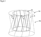
- second or further optoelectronic distance sensors are arranged in a ring in a second ring 14 on the movable machine part.
- a second protective field 5 can be generated, which is arranged, for example, in front of the first protective field 5 or also forms a more complex protective field 5 together with the first optoelectronic distance sensors.
- a part of the optoelectronic distance sensors forms a warning field 15.
- the other optoelectronic distance sensors form a protective field 5.
- a warning field 15 can be generated, which is arranged, for example, in front of the first protective field.
- optical axes 9 of the distance sensors are also aligned in a star shape and parallel to a plane of the ring. This forms a flat, ring-shaped protective field 5 in order to detect and avoid collisions when moving in the direction of the plane of the ring.
- second optoelectronic distance sensors are arranged in a ring in a second ring on the movable machine part.
- a second protective field 5 can be generated, which is arranged, for example, in front of the first protective field 5 or also forms a more complex protective field together with the first optoelectronic distance sensors. For example, it is possible to create a double-cylindrical protective field.
- the directions of the individual optical axis 9 for each circular arrangement are opposite or opposite to one another. In this way, for example, a closer-meshed or denser protective field 5 can be formed.
- the distance sensors 2 have according to Figure 5 each have a flat protective field 5.
- the flat protective field 5 is designed in a fan shape with a certain opening angle of, for example, 2 ° to 20 °.
- the optical axes 9 of the distance sensors additionally each have an identical acute angle ⁇ to a central axis 12 of the movable machine part.
- a frustoconical protective field 5 is thereby formed. The smaller the angle, the more acute the truncated cone is. The smaller the distance between a workpiece / gripper and the background, the lower the approach speed should be, and thus also the protected volume.
- Figure 8 shows schematically the protective field 5 according to Figure 5 .
- Figure 9 shows a cross section approximately transversely to the optical axes when approaching a flat object.
- the light spot moves dynamically in the ring and thus changes its local position.
- the inclination of the optical axes of the distance sensors leads according to Figure 9 to dynamize the protective field gaps or protective jacket gaps and thus enables the detection of objects that are temporarily located in these gaps when the machine part approaches an object.
- the sensor system ensures that a defined object is no later than after covering a certain distance of the movable Machine part is detected.
- the probe beam shifts when the machine part approaches, relative to a static object in the monitoring area.
- Second optoelectronic distance sensors are arranged in a ring in a second ring 14 on the movable machine part.
- a second protective field 5 can be generated, which is arranged, for example, in front of the first protective field or also forms a more complex protective field 5 together with the first optoelectronic distance sensors.
- Second optoelectronic distance sensors are arranged in a ring in a second ring 14 on the movable machine part.
- a second protective field 5 can be generated, which is arranged, for example, in front of the first protective field 5 or also forms a more complex protective field 5 together with the first optoelectronic distance sensors.
- the directions of the individual optical axis 9 for each annular arrangement are opposite or opposite to one another. In this way, for example, a closer-meshed or denser protective field 5 can be formed.
- the sensors are rotatably arranged on the ring.
- the rotation of the optical axes of the distance sensors leads to an additional dynamization of the protective field gaps or protective jacket gaps and thus enables the detection of objects that are located in these gaps during the rotational movement.
- the sensor system ensures that a defined object is detected after a certain time at the latest. This time then depends on the rotation path or the rotation speed.
Landscapes
- Engineering & Computer Science (AREA)
- Physics & Mathematics (AREA)
- General Physics & Mathematics (AREA)
- General Engineering & Computer Science (AREA)
- Electromagnetism (AREA)
- Computer Networks & Wireless Communication (AREA)
- Radar, Positioning & Navigation (AREA)
- Remote Sensing (AREA)
- Mechanical Engineering (AREA)
- Life Sciences & Earth Sciences (AREA)
- General Life Sciences & Earth Sciences (AREA)
- Geophysics (AREA)
- Length Measuring Devices By Optical Means (AREA)
Claims (8)
- Système de capteurs (1) comportant des capteurs de distance optoélectroniques (2) pour surveiller une zone de danger (3) sur une partie de machine mobile (4), présentant au moins un champ de protection (5), dans lequel les capteurs de distance optoélectroniques (2) sont disposés sous forme annulaire en un premier anneau (6) sur la partie de machine mobile (4), un outil (4) et/ou une pièce à œuvrer est disposé(e) sur la partie de machine mobile (4),
les axes optiques (9) des faisceaux de détection (11) des capteurs de distance (2) du premier anneau (6) forment chacun un angle aigu (α) tangentiellement à la forme annulaire,
caractérisé en ce que des seconds capteurs de distance optoélectroniques (2) sont disposés sou forme annulaire en un second anneau (14) sur la partie de machine mobile (4). - Système de capteurs (1) comportant des capteurs de distance optoélectroniques (2) pour surveiller une zone de danger (3) sur une partie de machine mobile (4), présentant au moins un champ de protection (5), dans lequel les capteurs de distance optoélectroniques (2) sont disposés sous forme annulaire en un premier anneau (6) sur la partie de machine mobile (4), un outil (4) et/ou une pièce à œuvrer est disposé(e) sur la partie de machine mobile (4),
caractérisé en ce que les capteurs de distance (2) sont disposés de manière rotative sur l'anneau (6). - Système de capteurs (1) comportant des capteurs de distance optoélectroniques (2) selon la revendication 1 ou 2, caractérisé en ce que les axes optiques (9) des capteurs de distance (2) présentent un angle aigu (β) par rapport à un axe central (12) de la partie de machine mobile (4), de manière à former un champ de protection (5) de forme tronconique.
- Système de capteurs (1) comportant des capteurs de distance optoélectroniques (2) selon la revendication 1 ou 2, caractérisé en ce que les axes optiques (9) des capteurs de distance (2) sont orientés en forme d'étoile, parallèlement à un plan de l'anneau (6).
- Système de capteurs (1) comportant des capteurs de distance optoélectroniques (2) selon la revendication 2, caractérisé en ce que des seconds capteurs de distance optoélectroniques (2) sont disposés sous forme annulaire en un second anneau (14) sur la partie de machine mobile (4).
- Système de capteurs (1) comportant des capteurs de distance optoélectroniques (2) selon l'une au moins des revendications précédentes, caractérisé en ce que les capteurs de distance optoélectroniques (2) forment un champ d'alerte (15) et/ou un champ de protection (5).
- Système de capteurs (1) comportant des capteurs de distance optoélectroniques (2) selon la revendication 1, caractérisé en ce que les capteurs de distance (2) sont disposés de manière rotative sur l'anneau (6).
- Système de capteurs (1) comportant des capteurs de distance optoélectroniques (2) selon l'une au moins des revendications précédentes, caractérisé en ce que les axes optiques (9) des capteurs de distance optiques (2) du second anneau (14) présentent un angle obtus (α2) tangentiellement à la forme annulaire.
Applications Claiming Priority (1)
| Application Number | Priority Date | Filing Date | Title |
|---|---|---|---|
| DE102018113359.6A DE102018113359B4 (de) | 2018-06-05 | 2018-06-05 | Sensorsystem mit optoelektronischen Distanzsensoren |
Publications (2)
| Publication Number | Publication Date |
|---|---|
| EP3578867A1 EP3578867A1 (fr) | 2019-12-11 |
| EP3578867B1 true EP3578867B1 (fr) | 2021-01-20 |
Family
ID=66448472
Family Applications (1)
| Application Number | Title | Priority Date | Filing Date |
|---|---|---|---|
| EP19173301.3A Active EP3578867B1 (fr) | 2018-06-05 | 2019-05-08 | Système de détecteurs pourvu de détecteurs de distance optoélectroniques |
Country Status (3)
| Country | Link |
|---|---|
| US (1) | US11879974B2 (fr) |
| EP (1) | EP3578867B1 (fr) |
| DE (1) | DE102018113359B4 (fr) |
Families Citing this family (2)
| Publication number | Priority date | Publication date | Assignee | Title |
|---|---|---|---|---|
| DE102020106161B3 (de) * | 2020-03-06 | 2020-11-26 | Sick Ag | System |
| DE102022100840A1 (de) * | 2022-01-14 | 2023-07-20 | Sick Ag | Augmented-reality-system zum unterrichten eines anwenders einer applikation |
Family Cites Families (11)
| Publication number | Priority date | Publication date | Assignee | Title |
|---|---|---|---|---|
| GB9805445D0 (en) * | 1998-03-16 | 1998-05-13 | Whitehouse John A | Product scanner |
| DE102004041821A1 (de) * | 2004-08-27 | 2006-03-16 | Abb Research Ltd. | Vorrichtung und Verfahren zur Sicherung eines maschinell gesteuerten Handhabungsgerätes |
| CA2889281A1 (fr) * | 2013-09-30 | 2015-04-02 | Vysoka Skola Banska - Technicka Univerzita Ostrava | Procede de mesure sans contact des dimensions exterieures de sections transversales d'un materiau en tige de metallurgie et cadre modulaire pour le mettre en uvre |
| DE102014012563B4 (de) | 2014-08-04 | 2018-10-25 | Abb Schweiz Ag | Näherungssensorik für einen Roboter |
| US10488192B2 (en) * | 2015-05-10 | 2019-11-26 | Magik Eye Inc. | Distance sensor projecting parallel patterns |
| US10634813B2 (en) * | 2015-05-18 | 2020-04-28 | Lasermotive, Inc. | Multi-layered safety system |
| DE102015112656A1 (de) | 2015-07-31 | 2017-02-02 | Sick Ag | Distanzsensor |
| DE102015113338B4 (de) * | 2015-08-13 | 2017-10-05 | Karl Leibinger Medizintechnik Gmbh & Co. Kg | Handgriffvorrichtung für eine Operationsleuchte mit Sprachsteuerung sowie Operationsleuchte |
| DE102016103028A1 (de) | 2016-02-22 | 2017-08-24 | Sick Ag | Vorrichtung zum Überwachen eines Überwachungsbereichs |
| DE202017100522U1 (de) * | 2017-01-31 | 2018-05-03 | Sick Ag | Überwachungseinrichtung |
| DE102017105999B3 (de) * | 2017-03-21 | 2018-03-01 | Sick Ag | Sensorsystem für einen mehrgliedrigen Roboter |
-
2018
- 2018-06-05 DE DE102018113359.6A patent/DE102018113359B4/de not_active Expired - Fee Related
-
2019
- 2019-05-08 EP EP19173301.3A patent/EP3578867B1/fr active Active
- 2019-06-04 US US16/431,150 patent/US11879974B2/en active Active
Non-Patent Citations (1)
| Title |
|---|
| None * |
Also Published As
| Publication number | Publication date |
|---|---|
| EP3578867A1 (fr) | 2019-12-11 |
| DE102018113359A1 (de) | 2019-12-05 |
| US11879974B2 (en) | 2024-01-23 |
| DE102018113359B4 (de) | 2020-07-30 |
| US20190369249A1 (en) | 2019-12-05 |
Similar Documents
| Publication | Publication Date | Title |
|---|---|---|
| EP3136127B1 (fr) | Capteur telemetrique et procede comprenant un capteur telemetrique | |
| EP1046925B1 (fr) | Dispositif optoélectronique | |
| EP2180348B1 (fr) | Barrière lumineuse de sécurité et procédé correspondant de surveillance d'une zone de protection | |
| EP2937715B1 (fr) | Capteur optoélectronique et procédé destiné à la détection d'informations de mesure dans une zone de surveillance | |
| EP4124789B1 (fr) | Fixation d'une pièce de machine mobile | |
| EP3418846B1 (fr) | Dispositif de commande de sécurité d'une machine | |
| EP3875228B1 (fr) | Système de surveillance d'une zone de danger sur une partie mobile de machine | |
| DE102018113359B4 (de) | Sensorsystem mit optoelektronischen Distanzsensoren | |
| EP2375264A1 (fr) | Scanner de sécurité avec surveillance d'encrassement | |
| EP3208511B1 (fr) | Dispositif de surveillance d'une zone de surveillance d'un véhicule sans conducteur | |
| EP3578324B1 (fr) | Système de détecteurs pourvu de détecteurs de distance optoélectroniques | |
| EP3597983B1 (fr) | Système de capteur et module de capteur de distance | |
| DE202017104603U1 (de) | System zum Absichern einer Maschine | |
| DE102018113362B4 (de) | Sensorsystem mit optoelektronischen Distanzsensormodulen | |
| EP3640522B1 (fr) | Dispositif de surveillance | |
| DE102017119283B4 (de) | Sensorsystem | |
| EP3671289B1 (fr) | Système de détection | |
| DE202008016946U1 (de) | Lichtgitter oder Lichtschranke | |
| EP3415951B1 (fr) | Capteur optique | |
| EP4306998A1 (fr) | Capteur optique | |
| DE202017103611U1 (de) | Vorrichtung zur Sicherheitssteuerung einer Maschine | |
| EP3540380B1 (fr) | Dispositif de surveillance pour une installation | |
| DE202020101253U1 (de) | System | |
| EP3955022A1 (fr) | Agencement de capteurs et son procédé de fonctionnement | |
| DE202019103672U1 (de) | Sensorsystem |
Legal Events
| Date | Code | Title | Description |
|---|---|---|---|
| PUAI | Public reference made under article 153(3) epc to a published international application that has entered the european phase |
Free format text: ORIGINAL CODE: 0009012 |
|
| STAA | Information on the status of an ep patent application or granted ep patent |
Free format text: STATUS: THE APPLICATION HAS BEEN PUBLISHED |
|
| AK | Designated contracting states |
Kind code of ref document: A1 Designated state(s): AL AT BE BG CH CY CZ DE DK EE ES FI FR GB GR HR HU IE IS IT LI LT LU LV MC MK MT NL NO PL PT RO RS SE SI SK SM TR |
|
| AX | Request for extension of the european patent |
Extension state: BA ME |
|
| STAA | Information on the status of an ep patent application or granted ep patent |
Free format text: STATUS: REQUEST FOR EXAMINATION WAS MADE |
|
| RAP1 | Party data changed (applicant data changed or rights of an application transferred) |
Owner name: SICK AG |
|
| 17P | Request for examination filed |
Effective date: 20200211 |
|
| RBV | Designated contracting states (corrected) |
Designated state(s): AL AT BE BG CH CY CZ DE DK EE ES FI FR GB GR HR HU IE IS IT LI LT LU LV MC MK MT NL NO PL PT RO RS SE SI SK SM TR |
|
| STAA | Information on the status of an ep patent application or granted ep patent |
Free format text: STATUS: EXAMINATION IS IN PROGRESS |
|
| 17Q | First examination report despatched |
Effective date: 20200619 |
|
| GRAP | Despatch of communication of intention to grant a patent |
Free format text: ORIGINAL CODE: EPIDOSNIGR1 |
|
| STAA | Information on the status of an ep patent application or granted ep patent |
Free format text: STATUS: GRANT OF PATENT IS INTENDED |
|
| INTG | Intention to grant announced |
Effective date: 20201105 |
|
| GRAS | Grant fee paid |
Free format text: ORIGINAL CODE: EPIDOSNIGR3 |
|
| GRAA | (expected) grant |
Free format text: ORIGINAL CODE: 0009210 |
|
| STAA | Information on the status of an ep patent application or granted ep patent |
Free format text: STATUS: THE PATENT HAS BEEN GRANTED |
|
| AK | Designated contracting states |
Kind code of ref document: B1 Designated state(s): AL AT BE BG CH CY CZ DE DK EE ES FI FR GB GR HR HU IE IS IT LI LT LU LV MC MK MT NL NO PL PT RO RS SE SI SK SM TR |
|
| REG | Reference to a national code |
Ref country code: GB Ref legal event code: FG4D Free format text: NOT ENGLISH |
|
| REG | Reference to a national code |
Ref country code: CH Ref legal event code: EP |
|
| REG | Reference to a national code |
Ref country code: AT Ref legal event code: REF Ref document number: 1356716 Country of ref document: AT Kind code of ref document: T Effective date: 20210215 |
|
| REG | Reference to a national code |
Ref country code: IE Ref legal event code: FG4D Free format text: LANGUAGE OF EP DOCUMENT: GERMAN |
|
| REG | Reference to a national code |
Ref country code: DE Ref legal event code: R096 Ref document number: 502019000718 Country of ref document: DE |
|
| REG | Reference to a national code |
Ref country code: NL Ref legal event code: MP Effective date: 20210120 |
|
| REG | Reference to a national code |
Ref country code: LT Ref legal event code: MG9D |
|
| PG25 | Lapsed in a contracting state [announced via postgrant information from national office to epo] |
Ref country code: PT Free format text: LAPSE BECAUSE OF FAILURE TO SUBMIT A TRANSLATION OF THE DESCRIPTION OR TO PAY THE FEE WITHIN THE PRESCRIBED TIME-LIMIT Effective date: 20210520 Ref country code: NO Free format text: LAPSE BECAUSE OF FAILURE TO SUBMIT A TRANSLATION OF THE DESCRIPTION OR TO PAY THE FEE WITHIN THE PRESCRIBED TIME-LIMIT Effective date: 20210420 Ref country code: LT Free format text: LAPSE BECAUSE OF FAILURE TO SUBMIT A TRANSLATION OF THE DESCRIPTION OR TO PAY THE FEE WITHIN THE PRESCRIBED TIME-LIMIT Effective date: 20210120 Ref country code: BG Free format text: LAPSE BECAUSE OF FAILURE TO SUBMIT A TRANSLATION OF THE DESCRIPTION OR TO PAY THE FEE WITHIN THE PRESCRIBED TIME-LIMIT Effective date: 20210420 Ref country code: HR Free format text: LAPSE BECAUSE OF FAILURE TO SUBMIT A TRANSLATION OF THE DESCRIPTION OR TO PAY THE FEE WITHIN THE PRESCRIBED TIME-LIMIT Effective date: 20210120 Ref country code: FI Free format text: LAPSE BECAUSE OF FAILURE TO SUBMIT A TRANSLATION OF THE DESCRIPTION OR TO PAY THE FEE WITHIN THE PRESCRIBED TIME-LIMIT Effective date: 20210120 Ref country code: GR Free format text: LAPSE BECAUSE OF FAILURE TO SUBMIT A TRANSLATION OF THE DESCRIPTION OR TO PAY THE FEE WITHIN THE PRESCRIBED TIME-LIMIT Effective date: 20210421 |
|
| PG25 | Lapsed in a contracting state [announced via postgrant information from national office to epo] |
Ref country code: SE Free format text: LAPSE BECAUSE OF FAILURE TO SUBMIT A TRANSLATION OF THE DESCRIPTION OR TO PAY THE FEE WITHIN THE PRESCRIBED TIME-LIMIT Effective date: 20210120 Ref country code: PL Free format text: LAPSE BECAUSE OF FAILURE TO SUBMIT A TRANSLATION OF THE DESCRIPTION OR TO PAY THE FEE WITHIN THE PRESCRIBED TIME-LIMIT Effective date: 20210120 Ref country code: RS Free format text: LAPSE BECAUSE OF FAILURE TO SUBMIT A TRANSLATION OF THE DESCRIPTION OR TO PAY THE FEE WITHIN THE PRESCRIBED TIME-LIMIT Effective date: 20210120 Ref country code: LV Free format text: LAPSE BECAUSE OF FAILURE TO SUBMIT A TRANSLATION OF THE DESCRIPTION OR TO PAY THE FEE WITHIN THE PRESCRIBED TIME-LIMIT Effective date: 20210120 |
|
| PG25 | Lapsed in a contracting state [announced via postgrant information from national office to epo] |
Ref country code: IS Free format text: LAPSE BECAUSE OF FAILURE TO SUBMIT A TRANSLATION OF THE DESCRIPTION OR TO PAY THE FEE WITHIN THE PRESCRIBED TIME-LIMIT Effective date: 20210520 |
|
| REG | Reference to a national code |
Ref country code: DE Ref legal event code: R097 Ref document number: 502019000718 Country of ref document: DE |
|
| PG25 | Lapsed in a contracting state [announced via postgrant information from national office to epo] |
Ref country code: CZ Free format text: LAPSE BECAUSE OF FAILURE TO SUBMIT A TRANSLATION OF THE DESCRIPTION OR TO PAY THE FEE WITHIN THE PRESCRIBED TIME-LIMIT Effective date: 20210120 Ref country code: EE Free format text: LAPSE BECAUSE OF FAILURE TO SUBMIT A TRANSLATION OF THE DESCRIPTION OR TO PAY THE FEE WITHIN THE PRESCRIBED TIME-LIMIT Effective date: 20210120 Ref country code: SM Free format text: LAPSE BECAUSE OF FAILURE TO SUBMIT A TRANSLATION OF THE DESCRIPTION OR TO PAY THE FEE WITHIN THE PRESCRIBED TIME-LIMIT Effective date: 20210120 |
|
| PLBE | No opposition filed within time limit |
Free format text: ORIGINAL CODE: 0009261 |
|
| STAA | Information on the status of an ep patent application or granted ep patent |
Free format text: STATUS: NO OPPOSITION FILED WITHIN TIME LIMIT |
|
| PG25 | Lapsed in a contracting state [announced via postgrant information from national office to epo] |
Ref country code: SK Free format text: LAPSE BECAUSE OF FAILURE TO SUBMIT A TRANSLATION OF THE DESCRIPTION OR TO PAY THE FEE WITHIN THE PRESCRIBED TIME-LIMIT Effective date: 20210120 Ref country code: RO Free format text: LAPSE BECAUSE OF FAILURE TO SUBMIT A TRANSLATION OF THE DESCRIPTION OR TO PAY THE FEE WITHIN THE PRESCRIBED TIME-LIMIT Effective date: 20210120 Ref country code: DK Free format text: LAPSE BECAUSE OF FAILURE TO SUBMIT A TRANSLATION OF THE DESCRIPTION OR TO PAY THE FEE WITHIN THE PRESCRIBED TIME-LIMIT Effective date: 20210120 |
|
| 26N | No opposition filed |
Effective date: 20211021 |
|
| PG25 | Lapsed in a contracting state [announced via postgrant information from national office to epo] |
Ref country code: MC Free format text: LAPSE BECAUSE OF FAILURE TO SUBMIT A TRANSLATION OF THE DESCRIPTION OR TO PAY THE FEE WITHIN THE PRESCRIBED TIME-LIMIT Effective date: 20210120 Ref country code: LU Free format text: LAPSE BECAUSE OF NON-PAYMENT OF DUE FEES Effective date: 20210508 Ref country code: AL Free format text: LAPSE BECAUSE OF FAILURE TO SUBMIT A TRANSLATION OF THE DESCRIPTION OR TO PAY THE FEE WITHIN THE PRESCRIBED TIME-LIMIT Effective date: 20210120 Ref country code: ES Free format text: LAPSE BECAUSE OF FAILURE TO SUBMIT A TRANSLATION OF THE DESCRIPTION OR TO PAY THE FEE WITHIN THE PRESCRIBED TIME-LIMIT Effective date: 20210120 |
|
| REG | Reference to a national code |
Ref country code: BE Ref legal event code: MM Effective date: 20210531 |
|
| PG25 | Lapsed in a contracting state [announced via postgrant information from national office to epo] |
Ref country code: SI Free format text: LAPSE BECAUSE OF FAILURE TO SUBMIT A TRANSLATION OF THE DESCRIPTION OR TO PAY THE FEE WITHIN THE PRESCRIBED TIME-LIMIT Effective date: 20210120 |
|
| PG25 | Lapsed in a contracting state [announced via postgrant information from national office to epo] |
Ref country code: IT Free format text: LAPSE BECAUSE OF FAILURE TO SUBMIT A TRANSLATION OF THE DESCRIPTION OR TO PAY THE FEE WITHIN THE PRESCRIBED TIME-LIMIT Effective date: 20210120 Ref country code: IE Free format text: LAPSE BECAUSE OF NON-PAYMENT OF DUE FEES Effective date: 20210508 |
|
| PG25 | Lapsed in a contracting state [announced via postgrant information from national office to epo] |
Ref country code: IS Free format text: LAPSE BECAUSE OF FAILURE TO SUBMIT A TRANSLATION OF THE DESCRIPTION OR TO PAY THE FEE WITHIN THE PRESCRIBED TIME-LIMIT Effective date: 20210520 |
|
| PG25 | Lapsed in a contracting state [announced via postgrant information from national office to epo] |
Ref country code: BE Free format text: LAPSE BECAUSE OF NON-PAYMENT OF DUE FEES Effective date: 20210531 |
|
| REG | Reference to a national code |
Ref country code: CH Ref legal event code: PL |
|
| PG25 | Lapsed in a contracting state [announced via postgrant information from national office to epo] |
Ref country code: LI Free format text: LAPSE BECAUSE OF NON-PAYMENT OF DUE FEES Effective date: 20220531 Ref country code: CH Free format text: LAPSE BECAUSE OF NON-PAYMENT OF DUE FEES Effective date: 20220531 |
|
| PG25 | Lapsed in a contracting state [announced via postgrant information from national office to epo] |
Ref country code: NL Free format text: LAPSE BECAUSE OF NON-PAYMENT OF DUE FEES Effective date: 20210120 Ref country code: CY Free format text: LAPSE BECAUSE OF FAILURE TO SUBMIT A TRANSLATION OF THE DESCRIPTION OR TO PAY THE FEE WITHIN THE PRESCRIBED TIME-LIMIT Effective date: 20210120 |
|
| PG25 | Lapsed in a contracting state [announced via postgrant information from national office to epo] |
Ref country code: HU Free format text: LAPSE BECAUSE OF FAILURE TO SUBMIT A TRANSLATION OF THE DESCRIPTION OR TO PAY THE FEE WITHIN THE PRESCRIBED TIME-LIMIT; INVALID AB INITIO Effective date: 20190508 |
|
| PG25 | Lapsed in a contracting state [announced via postgrant information from national office to epo] |
Ref country code: MK Free format text: LAPSE BECAUSE OF FAILURE TO SUBMIT A TRANSLATION OF THE DESCRIPTION OR TO PAY THE FEE WITHIN THE PRESCRIBED TIME-LIMIT Effective date: 20210120 |
|
| PG25 | Lapsed in a contracting state [announced via postgrant information from national office to epo] |
Ref country code: MT Free format text: LAPSE BECAUSE OF FAILURE TO SUBMIT A TRANSLATION OF THE DESCRIPTION OR TO PAY THE FEE WITHIN THE PRESCRIBED TIME-LIMIT Effective date: 20210120 |
|
| PGFP | Annual fee paid to national office [announced via postgrant information from national office to epo] |
Ref country code: DE Payment date: 20250519 Year of fee payment: 7 |
|
| REG | Reference to a national code |
Ref country code: AT Ref legal event code: MM01 Ref document number: 1356716 Country of ref document: AT Kind code of ref document: T Effective date: 20240508 |
|
| PGFP | Annual fee paid to national office [announced via postgrant information from national office to epo] |
Ref country code: FR Payment date: 20250523 Year of fee payment: 7 |
|
| PG25 | Lapsed in a contracting state [announced via postgrant information from national office to epo] |
Ref country code: AT Free format text: LAPSE BECAUSE OF NON-PAYMENT OF DUE FEES Effective date: 20240508 |
|
| PG25 | Lapsed in a contracting state [announced via postgrant information from national office to epo] |
Ref country code: TR Free format text: LAPSE BECAUSE OF FAILURE TO SUBMIT A TRANSLATION OF THE DESCRIPTION OR TO PAY THE FEE WITHIN THE PRESCRIBED TIME-LIMIT Effective date: 20210120 |
|
| PGFP | Annual fee paid to national office [announced via postgrant information from national office to epo] |
Ref country code: GB Payment date: 20260324 Year of fee payment: 8 |
|
| PGFP | Annual fee paid to national office [announced via postgrant information from national office to epo] |
Ref country code: AT Payment date: 20260410 Year of fee payment: 5 |