EP3579095B1 - Dispositif électronique portable, procédé de fonctionnement correspondant et support d'enregistrement lisible par ordinateur non transitoire - Google Patents
Dispositif électronique portable, procédé de fonctionnement correspondant et support d'enregistrement lisible par ordinateur non transitoire Download PDFInfo
- Publication number
- EP3579095B1 EP3579095B1 EP19187612.7A EP19187612A EP3579095B1 EP 3579095 B1 EP3579095 B1 EP 3579095B1 EP 19187612 A EP19187612 A EP 19187612A EP 3579095 B1 EP3579095 B1 EP 3579095B1
- Authority
- EP
- European Patent Office
- Prior art keywords
- squeezing
- threshold
- electronic device
- portable electronic
- action
- Prior art date
- Legal status (The legal status is an assumption and is not a legal conclusion. Google has not performed a legal analysis and makes no representation as to the accuracy of the status listed.)
- Active
Links
Images









Classifications
-
- G—PHYSICS
- G06—COMPUTING OR CALCULATING; COUNTING
- G06F—ELECTRIC DIGITAL DATA PROCESSING
- G06F3/00—Input arrangements for transferring data to be processed into a form capable of being handled by the computer; Output arrangements for transferring data from processing unit to output unit, e.g. interface arrangements
- G06F3/01—Input arrangements or combined input and output arrangements for interaction between user and computer
- G06F3/048—Interaction techniques based on graphical user interfaces [GUI]
- G06F3/0487—Interaction techniques based on graphical user interfaces [GUI] using specific features provided by the input device, e.g. functions controlled by the rotation of a mouse with dual sensing arrangements, or of the nature of the input device, e.g. tap gestures based on pressure sensed by a digitiser
- G06F3/0488—Interaction techniques based on graphical user interfaces [GUI] using specific features provided by the input device, e.g. functions controlled by the rotation of a mouse with dual sensing arrangements, or of the nature of the input device, e.g. tap gestures based on pressure sensed by a digitiser using a touch-screen or digitiser, e.g. input of commands through traced gestures
- G06F3/04883—Interaction techniques based on graphical user interfaces [GUI] using specific features provided by the input device, e.g. functions controlled by the rotation of a mouse with dual sensing arrangements, or of the nature of the input device, e.g. tap gestures based on pressure sensed by a digitiser using a touch-screen or digitiser, e.g. input of commands through traced gestures for inputting data by handwriting, e.g. gesture or text
-
- G—PHYSICS
- G06—COMPUTING OR CALCULATING; COUNTING
- G06F—ELECTRIC DIGITAL DATA PROCESSING
- G06F3/00—Input arrangements for transferring data to be processed into a form capable of being handled by the computer; Output arrangements for transferring data from processing unit to output unit, e.g. interface arrangements
- G06F3/01—Input arrangements or combined input and output arrangements for interaction between user and computer
- G06F3/048—Interaction techniques based on graphical user interfaces [GUI]
- G06F3/0481—Interaction techniques based on graphical user interfaces [GUI] based on specific properties of the displayed interaction object or a metaphor-based environment, e.g. interaction with desktop elements like windows or icons, or assisted by a cursor's changing behaviour or appearance
- G06F3/0482—Interaction with lists of selectable items, e.g. menus
-
- G—PHYSICS
- G06—COMPUTING OR CALCULATING; COUNTING
- G06F—ELECTRIC DIGITAL DATA PROCESSING
- G06F1/00—Details not covered by groups G06F3/00 - G06F13/00 and G06F21/00
- G06F1/16—Constructional details or arrangements
- G06F1/1613—Constructional details or arrangements for portable computers
- G06F1/1633—Constructional details or arrangements of portable computers not specific to the type of enclosures covered by groups G06F1/1615 - G06F1/1626
- G06F1/1684—Constructional details or arrangements related to integrated I/O peripherals not covered by groups G06F1/1635 - G06F1/1675
- G06F1/169—Constructional details or arrangements related to integrated I/O peripherals not covered by groups G06F1/1635 - G06F1/1675 the I/O peripheral being an integrated pointing device, e.g. trackball in the palm rest area, mini-joystick integrated between keyboard keys, touch pads or touch stripes
- G06F1/1692—Constructional details or arrangements related to integrated I/O peripherals not covered by groups G06F1/1635 - G06F1/1675 the I/O peripheral being an integrated pointing device, e.g. trackball in the palm rest area, mini-joystick integrated between keyboard keys, touch pads or touch stripes the I/O peripheral being a secondary touch screen used as control interface, e.g. virtual buttons or sliders
-
- G—PHYSICS
- G06—COMPUTING OR CALCULATING; COUNTING
- G06F—ELECTRIC DIGITAL DATA PROCESSING
- G06F1/00—Details not covered by groups G06F3/00 - G06F13/00 and G06F21/00
- G06F1/26—Power supply means, e.g. regulation thereof
- G06F1/32—Means for saving power
- G06F1/3203—Power management, i.e. event-based initiation of a power-saving mode
- G06F1/3206—Monitoring of events, devices or parameters that trigger a change in power modality
-
- G—PHYSICS
- G06—COMPUTING OR CALCULATING; COUNTING
- G06F—ELECTRIC DIGITAL DATA PROCESSING
- G06F1/00—Details not covered by groups G06F3/00 - G06F13/00 and G06F21/00
- G06F1/26—Power supply means, e.g. regulation thereof
- G06F1/32—Means for saving power
- G06F1/3203—Power management, i.e. event-based initiation of a power-saving mode
- G06F1/3206—Monitoring of events, devices or parameters that trigger a change in power modality
- G06F1/3215—Monitoring of peripheral devices
-
- G—PHYSICS
- G06—COMPUTING OR CALCULATING; COUNTING
- G06F—ELECTRIC DIGITAL DATA PROCESSING
- G06F1/00—Details not covered by groups G06F3/00 - G06F13/00 and G06F21/00
- G06F1/26—Power supply means, e.g. regulation thereof
- G06F1/32—Means for saving power
- G06F1/3203—Power management, i.e. event-based initiation of a power-saving mode
- G06F1/3234—Power saving characterised by the action undertaken
- G06F1/325—Power saving in peripheral device
-
- G—PHYSICS
- G06—COMPUTING OR CALCULATING; COUNTING
- G06F—ELECTRIC DIGITAL DATA PROCESSING
- G06F1/00—Details not covered by groups G06F3/00 - G06F13/00 and G06F21/00
- G06F1/26—Power supply means, e.g. regulation thereof
- G06F1/32—Means for saving power
- G06F1/3203—Power management, i.e. event-based initiation of a power-saving mode
- G06F1/3234—Power saving characterised by the action undertaken
- G06F1/325—Power saving in peripheral device
- G06F1/3262—Power saving in digitizer or tablet
-
- G—PHYSICS
- G06—COMPUTING OR CALCULATING; COUNTING
- G06F—ELECTRIC DIGITAL DATA PROCESSING
- G06F3/00—Input arrangements for transferring data to be processed into a form capable of being handled by the computer; Output arrangements for transferring data from processing unit to output unit, e.g. interface arrangements
- G06F3/01—Input arrangements or combined input and output arrangements for interaction between user and computer
- G06F3/03—Arrangements for converting the position or the displacement of a member into a coded form
- G06F3/033—Pointing devices displaced or positioned by the user, e.g. mice, trackballs, pens or joysticks; Accessories therefor
- G06F3/0354—Pointing devices displaced or positioned by the user, e.g. mice, trackballs, pens or joysticks; Accessories therefor with detection of two-dimensional [2D] relative movements between the device, or an operating part thereof, and a plane or surface, e.g. 2D mice, trackballs, pens or pucks
- G06F3/03547—Touch pads, in which fingers can move on a surface
-
- G—PHYSICS
- G06—COMPUTING OR CALCULATING; COUNTING
- G06F—ELECTRIC DIGITAL DATA PROCESSING
- G06F3/00—Input arrangements for transferring data to be processed into a form capable of being handled by the computer; Output arrangements for transferring data from processing unit to output unit, e.g. interface arrangements
- G06F3/01—Input arrangements or combined input and output arrangements for interaction between user and computer
- G06F3/048—Interaction techniques based on graphical user interfaces [GUI]
- G06F3/0487—Interaction techniques based on graphical user interfaces [GUI] using specific features provided by the input device, e.g. functions controlled by the rotation of a mouse with dual sensing arrangements, or of the nature of the input device, e.g. tap gestures based on pressure sensed by a digitiser
-
- G—PHYSICS
- G06—COMPUTING OR CALCULATING; COUNTING
- G06F—ELECTRIC DIGITAL DATA PROCESSING
- G06F3/00—Input arrangements for transferring data to be processed into a form capable of being handled by the computer; Output arrangements for transferring data from processing unit to output unit, e.g. interface arrangements
- G06F3/01—Input arrangements or combined input and output arrangements for interaction between user and computer
- G06F3/048—Interaction techniques based on graphical user interfaces [GUI]
- G06F3/0487—Interaction techniques based on graphical user interfaces [GUI] using specific features provided by the input device, e.g. functions controlled by the rotation of a mouse with dual sensing arrangements, or of the nature of the input device, e.g. tap gestures based on pressure sensed by a digitiser
- G06F3/0488—Interaction techniques based on graphical user interfaces [GUI] using specific features provided by the input device, e.g. functions controlled by the rotation of a mouse with dual sensing arrangements, or of the nature of the input device, e.g. tap gestures based on pressure sensed by a digitiser using a touch-screen or digitiser, e.g. input of commands through traced gestures
-
- G—PHYSICS
- G06—COMPUTING OR CALCULATING; COUNTING
- G06F—ELECTRIC DIGITAL DATA PROCESSING
- G06F2200/00—Indexing scheme relating to G06F1/04 - G06F1/32
- G06F2200/16—Indexing scheme relating to G06F1/16 - G06F1/18
- G06F2200/163—Indexing scheme relating to constructional details of the computer
- G06F2200/1636—Sensing arrangement for detection of a tap gesture on the housing
-
- G—PHYSICS
- G06—COMPUTING OR CALCULATING; COUNTING
- G06F—ELECTRIC DIGITAL DATA PROCESSING
- G06F2200/00—Indexing scheme relating to G06F1/04 - G06F1/32
- G06F2200/16—Indexing scheme relating to G06F1/16 - G06F1/18
- G06F2200/163—Indexing scheme relating to constructional details of the computer
- G06F2200/1637—Sensing arrangement for detection of housing movement or orientation, e.g. for controlling scrolling or cursor movement on the display of an handheld computer
-
- G—PHYSICS
- G06—COMPUTING OR CALCULATING; COUNTING
- G06F—ELECTRIC DIGITAL DATA PROCESSING
- G06F2203/00—Indexing scheme relating to G06F3/00 - G06F3/048
- G06F2203/038—Indexing scheme relating to G06F3/038
- G06F2203/0382—Plural input, i.e. interface arrangements in which a plurality of input device of the same type are in communication with a PC
-
- G—PHYSICS
- G06—COMPUTING OR CALCULATING; COUNTING
- G06F—ELECTRIC DIGITAL DATA PROCESSING
- G06F3/00—Input arrangements for transferring data to be processed into a form capable of being handled by the computer; Output arrangements for transferring data from processing unit to output unit, e.g. interface arrangements
- G06F3/01—Input arrangements or combined input and output arrangements for interaction between user and computer
- G06F3/011—Arrangements for interaction with the human body, e.g. for user immersion in virtual reality
-
- G—PHYSICS
- G06—COMPUTING OR CALCULATING; COUNTING
- G06T—IMAGE DATA PROCESSING OR GENERATION, IN GENERAL
- G06T3/00—Geometric image transformations in the plane of the image
- G06T3/60—Rotation of whole images or parts thereof
-
- H—ELECTRICITY
- H04—ELECTRIC COMMUNICATION TECHNIQUE
- H04M—TELEPHONIC COMMUNICATION
- H04M2250/00—Details of telephonic subscriber devices
- H04M2250/22—Details of telephonic subscriber devices including a touch pad, a touch sensor or a touch detector
Definitions
- the disclosure relates to a portable electronic device, an operating method for the same, and a non-transitory computer readable recording medium, and more particularly to a portable electronic device comprising an edge sensor, an operating method for the same, and a non-transitory computer readable recording medium.
- a conventional portable electronic device such as cell phone, etc.
- the portable electronic device can perform a functional operating according to the sensed touch action.
- US2014/0123003 discloses how a second squeeze can contract or enlarge characters on a screen.
- This object can be achieved by the features as defined by the independent claims. Further enhancements are characterised by the dependent claims.
- the term embodiment is used for describing unclaimed combinations of features, the term has to be understood as referring to examples useful for understanding the present invention.
- the present disclosure provides a portable electronic device an operating method for the portable electronic device, and a non-transitory computer readable recording medium.
- an operating method for a portable electronic device comprises a body, a touch display screen and an edge sensor.
- the touch display screen is disposed on the body.
- the edge sensor is disposed adjacent to an edge of the body.
- the operating method includes the following step. When an event is generated according to a first action sensed by the edge sensor, a touch function of a region of the touch display screen or the whole touch display screen is disabled.
- a non-transitory computer readable recording medium for storing one or more programs.
- the one or more programs causing a processor to perform the above operating method after the one or more programs are loaded on a computer and are executed.
- a portable electronic device comprises a body, a processor, a touch display screen and an edge sensor.
- the touch display screen is disposed on the body.
- the edge sensor is electrically coupled to the process.
- the edge sensor is disposed adjacent to an edge of the body.
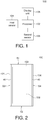
- FIG. 1 shows the block diagram of a portable electronic device 100 according to an embodiment of the invention.
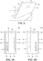
- FIG. 2 shows a schematic diagram of the portable electronic device 100.
- the portable electronic device 100 includes a body 103, processor 102, a first sensor 104, a second sensor 106, and a display unit 108.
- the processor 102 electrically coupled to the first sensor 104, the second sensor 106, and the display unit 108.
- the first sensor 104 or the second sensor 106 comprises an edge sensor 40 disposed adjacent to an edge of the body 103.
- each of the first sensor 104 and the second sensor 106 comprises the edge sensor 40 as shown in FIG. 1 .
- the display unit 108 comprises a touch display screen 109 disposed on the body 103.
- the portable electronic device 100 may be a smart phone or a tablet.
- the portable electronic device 100 includes a first side S1, a second side S2, a third side S3, and a fourth side S4.
- the first side S1 and the second side S2 are short sides of the portable electronic device 100
- the third side S3 and the fourth side S4 are long sides of the portable electronic device 100.
- the first sensor 104 and the second sensor 106 are, for example, pressure sensors, resistive sensors, optical sensors, or ultrasonic sensors.
- the edge sensor 40 may be implemented by at least one of pressure sensor and a touch sensor or other type sensors. Based on the actual needs of the present invention, the first sensor 104 or the second sensor 106 may be disposed on at least one short side of the electronic apparatus, it is not limited thereto.
- the processor 102 may include central processing units (CPUs) of the portable electronic device 100 and, thus, control the overall operation of portable electronic device 100. In certain embodiments, the processor 102 accomplishes this by executing software or firmware stored in the memory (not shown).
- the processor 102 may be, or may include, one or more programmable general-purpose or special-purpose microprocessors, digital signal processors (DSPs), programmable controllers, application specific integrated circuits (ASICs), programmable logic devices (PLDs), or the like, or a combination of such devices.
- the touch display screen 109 may include a liquid-crystal display (LCD), a plasma display, a vacuum fluorescent display, a light-emitting diode (LED) display, a field emission display, and/or other suitable types of display configured to display a user interface.
- LCD liquid-crystal display
- plasma display a plasma display
- vacuum fluorescent display a vacuum fluorescent display
- LED light-emitting diode
- field emission display a field emission display
- the first sensor 104 and the second sensor 106 are disposed on the third side S3 and fourth side S4 of the portable electronic device 100.
- the first sensor 104 and the second sensor 106 each includes a plurality of sensing components which are arranged in a line.
- the processor 102 determines the force applied to the sensing components according to the signals outputted from the sensing components of the first sensor 104 or/and the second sensor 106 when the user activates the first sensor 104 or/and the second sensor 106 of the portable electronic device 100.
- the processor 102 determines the activated positions on the long side of the portable electronic device 100 according to the positions of the sensing components which are activated by the user.
- the user actions on the portable electronic device 100 can be determined by the processor 102 according to the force applied and the positions activated on the first sensor 104 or/and the second sensor 106.
- the user actions may include squeezing the portable electronic device 100 (e.g., press the first sensor 104 and the second sensor 106 at the same time), sliding on the long side of the portable electronic device 100, pressing on the long side of the portable electronic device 100, and flipping the edge on the long side of the portable electronic device 100.
- the corresponding operations of the portable electronic device 100 are performed according to the user actions and the status of portable electronic device 100.
- the corresponding operations are performed when the user flips the edge (user action 1) in different statuses of the portable electronic device 100.
- the screen of the portable electronic device 100 is turned on/off (status B/A)
- a camera of the portable electronic device 100 is launched (status C)
- the user watches the video (status D)
- listens to the music (status E)
- plays the games (status F) on the portable electronic device 100
- the user is in a call (status G), an alarm/alert rings (status H)
- the user has an incoming call (status I)
- the user writes the Instant Message (IM)/message with input method editor (IME) (status J)
- the user writes the IM/message without IME (status K)
- the user browses the web/photo (status L)
- the user flips the edge to trigger the function of showing the edge sense panel on the touch display screen 109.
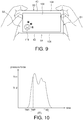
- FIG. 3 shows a schematic diagram of the portable electronic device 100 when the user flips the edge.
- the user action “flip the edge” represents that when the user holds the portable electronic device 100, the user uses a finger (for example, a thumb) to touch one of the long sides and moves the finger along a direction D1 from the rear cover 101 to the screen.
- the user action "flip the edge” may trigger at least one of the sensing components of the first sensor 104 or the second sensor 106 to output a corresponding sensing signal, and trigger the edge of the touch display screen 109 to output a corresponding touch signal.
- the processor 102 may receive the sensing signal and the touch signal, and accordingly determine the user action as "flip the edge" so as to perform a predefined function.
- FIG. 4A and FIG. 4B a schematic diagram of the edge sense panel is shown.
- the edge sense panel includes a first displaying area 110 and a second displaying area 112.
- the first displaying area 110 and the second displaying area 112 are displayed on the touch display screen 109 and near the long sides S3 and S4.
- the first displaying area 110 and the second displaying area 112 display the shortcut icon 114 and information 116, such that the user can touch the shortcut icon 114 and information 116 easily.
- the shortcut icon 114 corresponds to application, for example, "Instagram", “Facebook” or “Line”.
- the information 116 can include but not limit to images, weather or news.
- the touch display screen 109 displays the edge sense panel in which the shortcut icons 114 are displayed in the first displaying area 110 and the information 116 is displayed in the second displaying area 112 (as shown in FIG. 4A ).
- the touch display screen 109 displays the edge sense panel in which the information 116 is displayed in the first displaying area 110 and the shortcut icons 114 are displayed in the second displaying area 112 (as shown in FIG. 4B ).
- an indicator is displayed on one of the shortcut icons 114 or any information 116. The user can move the indicator by sliding and pressing on the long side of the portable electric device 100 so as to select and execute one of the shortcut icons 114 or display one information 116.
- the portable electric device 100 may detect which of the right hand and the left hand is holding the portable electric device 100 according to at least one finger position and a palm position sensed by the first sensor 104 and the second sensor 106. Specifically, when the sensor senses a dotted touch point (with a smaller area), the processor 102 determines that the dotted touch point is a finger touch, and the position of the dotted touch point is the finger position. When the sensor senses a sheeted touch point (with a larger area), the processor 102 determines that the sheeted touch point is a palm touch, and the position of the sheeted touch point is the palm position. Therefore, the processor 102 may determine the dotted touch point above the sheeted touch point as a thumb portion according to the palm position.
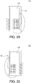
- the processor 102 may determine a display position of a keyboard image on the touch display screen 109 according to a gesture for holding the portable electric device 100 made by a user. In this way, it will be convenient for user to operate the device. For example, when the user uses the right hand to hold the portable electric device 100 (with the finger position on the third side S3 and the palm position on the fourth side S4), the touch display screen 109 displays the keyboard image in a region adjacent to the fourth side S4, as shown in FIG. 29 , to be closer to the right thumb of the user.
- the touch display screen 109 displays the keyboard image in a region adjacent to the third side S3, as shown in FIG. 30 , to be closer to the left thumb of the user. Therefore, the user could tap the keyboard with the thumb easily and precisely.
- the corresponding operations are performed when the user squeezes the portable electronic device 100 (user action 2) in different statuses of the portable electronic device 100.
- user squeezes the portable electronic device 100 For example, when a camera of the portable electronic device 100 is launched (status C), the user squeezes the portable electronic device 100 to take a photo or record a video.
- the user watches video (status D), listens to music (status E), or plays games on the portable electronic device 100 (status F)
- the user squeezes the portable electronic device 100 to pause/play the video, the music or the games.
- an alarm/alert rings (status H)
- FIG. 5 shows a schematic diagram of the portable electronic device 100 when the user squeezes the portable electronic device 100.
- the user action "squeeze” represents that when the user holds the portable electronic device 100, the user presses both opposing long sides of the portable electronic device 100 firmly with fingers or hands.
- the user action is determined by the processor 102 as “squeeze” when the signal level of the signals outputted from the sensing components of the first sensor 104 and the second sensor 106 simultaneously exceed a force threshold.
- the corresponding operations are performed when the user long squeezes the portable electronic device 100 (user action 3) in different statuses of the portable electronic device 100.
- a screen of the portable electronic device 100 is turned on/off (status B/A)
- a camera of the portable electronic device 100 is launched (status C)
- the user watches the video (status D)
- listens to the music (status E)
- plays the games on the portable electronic device 100 (status F)
- the user is in a call (incall) (status G)
- the user When an alarm/alert rings (status H), the user long squeezes the portable electronic device 100 to dismiss the alarm/alert.
- the user has an incoming call (status I)
- the user long squeezes the portable electronic device 100 to decline the incoming call.
- the user writes the IM/message with IME (status K)
- the user long squeezes the portable electronic device 100 to type with the voice (voice input).
- the user writes the IM/message without IME (status L)
- the user long squeezes the portable electronic device 100 to record and send the voice message.
- the user action "long squeeze” represents that the user continuously squeezes the first sensor 104 and the second sensor 106 of the portable electronic device 100 for a certain time longer than a time threshold. For example, the user action "long squeeze” is determined by the processor 102 when the time in which the user squeezes the portable electronic device 100 continuously is more than 3 seconds.
- the corresponding operations are performed when the user double squeezes the portable electronic device 100 (user action 4) in different statuses of the portable electronic device 100.
- the screen of the portable electronic device 100 is turned on/off (status B/A)
- the user watches the video (status D)
- the user is in a call (status G), an alarm/alert rings (status H)
- the user has an incoming call (status I)
- the user writes the IM/message with IME (status J)
- the user writes the IM/message without IME (status K)
- the user browses the web/photo (status L)
- the user action "double squeeze” represents that the user squeezes the first sensor 104 and the second sensor 106 of the portable electronic device 100 two times continuously within a certain time interval.
- the user action "double squeeze” is determined by the processor 102 when the user squeezes the portable electronic device 100 two times within two seconds.
- the corresponding operation for the user action "double squeeze” is customizable. That is, the user can reset the corresponding operation. For example, the corresponding operation "launch camera” is reset to "launch the favorite apps”.
- the corresponding operations are performed when a finger of the user slides on one of the two long sides of the portable electronic device 100 (user action 5) in different statuses of the portable electronic device 100.
- the sensing components in the first sensor 104 or the second sensor 106 continuously and sequentially output the sensing signals within a specific time period corresponding to the slide action made by the user, and the processor 102 determines the user action as "slide" according to the sensing signals so as to perform a predefined function. For example, when the screen of the portable electronic device 100 is turned on (status B), or the user browses the web/photo (status L), the user slides on the side of the portable electronic device 100 to scroll the page/content displayed on the touch display screen 109.
- the user finger slides on the up side (the third side S3) of the portable electronic device 100 in landscape mode to adjust the brightness or slides on the bottom side (the fourth side S4) of the portable electronic device 100 in landscape mode to zoom the content displayed on the touch display screen 109.
- the user watches the video (status D)
- the user finger slides on the up side (the third side S3) of the portable electronic device 100 in landscape mode to adjust the brightness or slides on the bottom side (the fourth side S4) of the portable electronic device 100 in landscape mode to adjust the progress bar.
- the user listens to the music (status E) the user finger slides on one of the third side S3 and the fourth side S4 to adjust the progress bar.
- FIG. 6 shows a schematic diagram of the portable electronic device 100 when the user finger slides on one of the two long sides of the portable electronic device 100.
- the user action "slide” represents that when the user holds the portable electronic device 100, the users uses a finger to touch one of the long sides and moves the finger along the touched long side.
- the corresponding operations are performed when the user finger slides on both long sides of the portable electronic device 100 (user action 6) in different statuses of the portable electronic device 100.
- the sensing components in the first sensor 104 and the second sensor 106 continuously and sequentially output the sensing signals within a specific time period corresponding to the slide action made by the user, and the processor 102 determines the user action according to the sensing signals.
- FIG. 7 shows a schematic diagram of the portable electronic device 100 when the user finger slides on both long sides of the portable electronic device 100.
- the user action "slide both sides” represents that when the user holds the portable electronic device 100, the user uses at least two fingers to touch both long sides and moves the at least two fingers along the both long sides simultaneously.
- the corresponding operations are performed when the user presses on a volume position (user action 7) in different statuses of the portable electronic device 100.
- the volume position is a specific position on the long sides. For example, when the screen of the portable electronic device 100 is turned on/off (status E), a camera of the portable electronic device 100 is launched (status C), the user watches the video (status D), listens to the music (status E), plays the games on the portable electronic device 100 (status F), the user is in a call (status G), an alarm/alert rings (status H), the user has an incoming call (status I), the user writes the IM/message with IME (status J), the user writes the IM/message without IME (status K), or the user browses the web/photo (status L), the user presses on the volume position on one of the two long sides of the portable electronic device 100 to adjust the volume.
- the user may press a first portion of the volume position (for example an upper portion of the one long side adjacent to the first side S1 of the portable electronic device 100) to increase the volume, or the user may press a second portion of the volume position opposite to the first portion (for example a lower portion of the one long side adjacent to the second side S2 of the portable electronic device 100) to decrease the volume.
- a first portion of the volume position for example an upper portion of the one long side adjacent to the first side S1 of the portable electronic device 100
- a second portion of the volume position opposite to the first portion for example a lower portion of the one long side adjacent to the second side S2 of the portable electronic device 100
- the corresponding operations are performed when the user holds the portable electronic device 100 with hands touching the third side S3 and the fourth side S4, and the user uses a finger to quickly slide on one of the two long sides (user action 8) in different statuses of the portable electronic device 100.
- the screen of the portable electronic device 100 is turned on/off (status B/A)
- the user watches the video (status D)
- the user is in a call (status G), an alarm/alert rings (status H)
- the user has an incoming call (status I)
- the user writes the IM/message with IME (status J)
- the user writes the IM/message without IME (status K)
- the user browses the web/photo (status L)
- the user holds the portable electronic device 100
- the user uses a finger to slide on one of the two long sides quickly to launch/dismiss the flashlight
- FIG. 8 shows a schematic diagram of the portable electronic device 100 when the user finger slides on one of the two long sides quickly of the portable electronic device 100.
- the user action "quick slide” represents that the user uses a finger to quickly slide on one of the two long sides for a distance larger than a distance threshold in a predefined period.
- the user action "quick slide” is determined by the processor 102 when the user slides on one of the two long sides over 5 centimeters.
- the corresponding operation for the user action "quick slide” is customizable. That is, the user can reset the corresponding operation.
- the corresponding operation “launch/dismiss the flashlight” is reset to "turn on a silent/ do not disturb (DND) mode” , “turn on an airplane mode", or “turn on Wi-Fi hotspot”.
- DND silent/ do not disturb
- the corresponding operations are performed when the user presses on the left and right parts on one of the long sides in the landscape mode (user action 9) in different statuses of the portable electronic device 100.
- the user plays the games in the landscape mode on the portable electronic device 100 (status F)
- the user presses the left and right parts on one of the long sides (for example, side S3) simultaneously in the landscape mode to launch the screen record widget.
- FIG. 9 shows a schematic diagram of the portable electronic device 100 when the user presses on the left and right parts on one of the long sides simultaneously in the landscape mode of the portable electronic device 100.
- the screen record widget 118 is a control interface for the game.
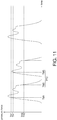
- a squeezing threshold TH1 is set for determining if a squeeze action begins, and a releasing threshold TH2 is set for determining if the squeeze action finishes.
- the releasing threshold TH2 is smaller than the squeezing threshold TH1.
- the squeezing threshold TH1 may be set through testing user's squeezing force during a squeezing setting procedure of the portable electronic device 100.
- the releasing threshold TH2 may be set according to the squeezing threshold TH1.
- the squeezing setting procedure may comprise asking the user to squeeze the portable electronic device 100, sensing test pressing forces F1 of user's squeezing the portable electronic device 100 with intention to trigger a functional operation of the portable electronic device 100 for several times by the sensing components, and determining a set pressing force F2 to be the squeezing threshold TH1 according to the test pressing forces F1 by the processor 102.
- the set pressing force F2 may be a percentile value of the test pressing forces F1.
- the test pressing forces F1 may be 100, 150, and 200 (pressure units)
- the set pressing force F2 (or the squeezing threshold TH1) is 175 (pressure units) being a percentile value of 75 th percentile calculated according to the minimum value of 100 (pressure units) and the maximum value of 200 (pressure units).
- the present disclosure is not limited thereto.
- the test pressing forces F1 may be 100, 150, and 200 (pressure units)
- the set pressing force F2 (or the squeezing threshold TH1) is 150 (pressure units), being an average value of the three test pressing forces F1.
- two or more the set pressing forces F2 can be set through the squeezing setting procedures.
- the set pressing forces F2 may be sorted in order (for example corresponding to 100, 150, 200 (pressure units) in sequence of size) as icons in a user interface, and one (for example 150 (pressure units)) of the two or more set pressing force F2 can be selected by the user as the squeezing threshold TH1. Then, if the user feels that the one set pressing force F2 (for example 150 (pressure units)) being the squeezing threshold TH1 does not fit for actual use, the user can set another one of the two or more set pressing force F2 as the squeezing threshold TH1.
- the user may reset 100 (pressure units) as the squeezing threshold TH1, which is lower than 150 (pressure units), as the user feels that 150 (pressure units) is too high; or reset 200 (pressure units) as the squeezing threshold TH1, which higher than 150 (pressure units), as the user feels that 150 (pressure units) is too low).
- the releasing threshold TH2 may be determined by the processor 102 according to the squeezing threshold TH1.
- the releasing threshold TH2 may be a specific ratio (smaller than 100%) of the squeezing threshold TH1.
- the value of the releasing threshold TH2 is 75% of the value of the squeezing threshold TH1.
- the squeezing threshold TH1 is 175 (pressure units)
- the releasing threshold TH2 is 131.25 (pressure units).
- the squeeze action is determined as being beginning by the processor 102.
- the pressing force of the pressing action beginning at the time point TM1 does not reach the squeezing threshold TH1
- no squeeze action is determined by the processor 102.
- the pressing action without reaching the squeezing threshold may comprise a normal holding action on the portable electronic device 100 by the user, and no functional operation of the portable electronic device 100 is triggered or determined by the processor 102.
- the processor 102 determines the squeeze action as an ineffective squeeze action, and thus no corresponding predefined function is performed. As long as the pressing force after reaching the squeezing threshold TH1 is lower than the releasing threshold TH2, it is determined by the processor 102 that the squeeze action of the user finishes. In other words, the processor 102 determines the squeeze action as an effective squeeze action, and thus the corresponding predefined function is performed.
- a time period PT1 between a time point TM2 and a time point TM3 corresponding to the squeezing threshold TH1 and the releasing threshold TH2 respectively is determined by the processor 102 as a time period of the squeeze action.
- the squeeze action can be determined by the processor 102 as a long squeeze action or a short squeeze action according to the time period PT1 between the time point TM2 and the time point TM3, comparing to a time threshold.
- the squeeze action is determined to be the short squeeze action.
- the squeeze action is determined to be the long squeeze action.
- a functional operational of the portable electronic device 100 may be determined by the processor 102 according to the squeeze action (the long squeeze action or the short squeeze action).
- a functional action corresponding to the sensed short/long squeeze action may be carried out by the portable electronic device 100.
- only the long squeeze action will trigger some particular functional action of the portable electronic device 100, while only the short squeeze action will be ignored by the portable electronic device 100.
- the values of the squeezing threshold TH1 and the releasing threshold TH2 may be adjusted dynamically by the processor 102 according to actual operating conditions of squeezing the portable electronic device 100 by the user. For example, if two or more squeeze actions are performed by the user with a short interval, for example for carrying out a picture capturing function rapidly and continuously, a subsequent squeeze action (or subsequent squeeze actions) after the first squeeze action may be determined according to the modified squeezing threshold TH1' and the modified releasing threshold TH2' obtained according to the squeezing threshold TH1 and the releasing threshold TH2, and smaller than the squeezing threshold TH1 and the releasing threshold TH2, respectively.
- the present disclosure is not limited thereto.
- the second squeeze action can be determined by the modified squeezing threshold TH1' and the modified releasing threshold TH2'.
- the third squeeze action can be determined by another modified thresholds TH1" and TH2" (not shown) obtained according to and smaller than the modified thresholds TH1' and TH2' respectively.
- TH1" 0.95*(TH1')
- TH2" 0.95*(TH2').
- the third squeeze action can be determined to be another first squeeze action that can be determined by the thresholds TH1 and TH2.
- the squeezing threshold can be adjusted dynamically.
- a squeezing threshold other than the squeezing threshold TH1 obtained by the setting procedure can be dynamically adjusted according to use's usual squeeze action not for the setting. For example, an average value of an area A ( FIG. 12 ) defined by the squeezing curve and the squeezing threshold TH1 is compared to a fixed specific value.
- the average value of an area A may be a pressure unit value calculated by dividing the area A by the time period of the area A.
- a squeezing threshold is adjusted dynamically to be lower than the original squeezing threshold TH1, and then a subsequent squeeze action is determined according to the adjusted squeezing threshold.
- a squeezing threshold is adjusted to be higher than the original squeezing threshold TH1, and then a subsequent squeeze action is determined according to the adjusted squeezing threshold.
- the squeezing threshold is not limited to the foregoing dynamic adjusting method, and may be decided according to other statistics schemes.
- a curve judged to be resulted from an un-normal squeeze action is not considered for dynamically adjusting the squeezing threshold. For example, it is judged according to a curvature value of a top point of the curve corresponding the area A, or a slope value of a portion near the top point of the curve. As the curvature value or the slope value is smaller than a fixed specific value, the squeeze action is determined as being an un-normal action, and therefore data obtained from which is not considered for dynamically adjusting the squeezing threshold.
- the pressing force during the pressing action can be shown as a visual image in the touch display screen 109 of the portable electronic device 100.
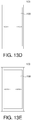
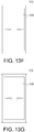
- the touch display screen 109 starts displaying an initial visual image ( FIG. 13A ) corresponding to a specific fixed pressure force TH3 as shown in FIG. 15 .
- the specific pressure force TH3 is lower than any one of the thresholds (such as TH1, TH1', TH1", etc., TH2, TH2', TH2", etc.) for determining whether the squeeze action is performed.
- the specific pressure force TH3 may be a fixed predetermined value without considering the setting procedure performed by the user.
- the visual image gradually changes to be images as shown in FIG. 13B to FIG. 13G in sequence, and further changes to be images as shown in FIG. 13H to FIG. 13I when the pressing force reaches to the threshold TH1 for indicating that the effective squeezing action is performed, and the predefined function is performed.
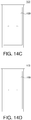
- the visual image gradually changes to be images as shown in FIG. 13B to FIG. 13G in sequence, and further changes to be gradually disappearing images as shown in FIG. 14A to FIG. 14D in sequence when the pressing force disappears at a time point shortly after the time point corresponding FIG. 13D , indicating that no effective squeezing action is performed, and thus no predefined function is performed.
- the touch function of a particular area of touch display screen 109 may be disabled according to a pressing action sensed by the edge sensor 40 of the portable electronic device 100.
- the touch function of a region 60 adjacent to the edge sensor 40 is disabled when the processor 102 via the first sensor 104 and/ or the second sensor 106 determines that the force of the pressing action (or squeeze action) is higher than a predefined value (e.g., threshold TH1), while a display function of the touch display screen 109 may be still active.
- the processor 102 restores the touch function of a region 60 adjacent to the edge sensor 40, when the force of the pressing action (or squeeze action) is smaller than a predefined value (e.g., threshold TH2).
- the touch function of the region 60 may be disabled during a time period between the time point corresponding to the threshold TH1 and the time point corresponding to the threshold TH2, and then be restored after the time point corresponding to the threshold TH2.
- the touch function of a region 60 is disabled in the time period PT1 shown in FIG. 10 .
- an area of the region 60 is gradually increased as being extended towards a center of the touch display screen 109 from the edge of the touch display screen 109.
- the width W of the region 60 may be increased as the pressing force increases sensed by the first sensor 104 and/ or the second sensor 104.
- the touch function of the whole touch display screen 109 is disabled as long as the processor 102 determines that the force of the pressing action (or the squeeze action) is higher than a predefined value (e.g., threshold TH1) without considering the change of the squeezing force.
- a predefined value e.g., threshold TH1
- a squeezing event sensed by the edge sensor is ignored.
- the squeezing event may be generated when the squeeze action sensed by the edge sensor occurs during a first time period.
- the plugging-in event or the plugging-out event occurs during the first time period.
- the squeeze action may begin within a second time period after the plugging-in event or the plugging-out event occurs.
- FIG. 17 shows the block diagram of the portable electronic device 200 according to another embodiment of the invention.
- the portable electronic device 200 further includes a detecting unit 233.
- the detecting unit 233 may be a detecting circuit for a port of USB, earphone, or other ports, for detecting a plugging-in event and a plugging-out event of a hardware element.
- the processor 102 electrically coupled to the first sensor 104, the second sensor 106, the display unit 108, and the detecting unit 233.
- a peripheral device 117 (as a client, for example a USB device) which is, for example, an earphone, a lighting device, an electric fan, or a flash drive etc., is detected by the detecting unit 233 to be plugged in or plugged out from the portable electronic device 200 (as a host) at a time point TM4 during the period time PT1, the squeezing event sensed by the edge sensor is ignored.
- the edge sensor 40 is disabled.
- the functional action corresponding to the sensed (short/long) squeezing event is canceled (not carried out) by the portable electronic device 200.
- the edge sensor 40 is disabled for a time period beginning at the timing point TM4, for example between the timing point TM4 and the timing port TM3, or between the timing point TM4 and a timing point later than the timing port TM3.
- the USB driver of the peripheral device 117 can inform a plugging in or plugging out event to a sensor hub as it happens, and no functional action correspond the state sensed by the edge sensor 40 is triggered to the portable electronic device 200. That is, the squeeze action around the time point TM4 which is between the time point TM2 and the time point TM3 is ignored. In an embodiment, the squeeze action after the time point TM4 with a specific time interval is ignored. For example, the squeeze action during a timing period between the timing point TM4 and the timing port TM3 may be ignored. The squeeze action during a timing period between the timing point TM4 and a timing point later than the timing port TM3 may be ignored. Alternatively, the squeeze action after the timing port TM3 may be ignored.
- FIG. 19 shows the block diagram of the portable electronic device 300 according to another embodiment of the invention.
- the portable electronic device 300 further includes a third sensor 210 and a G sensor 212.
- the processor 102 electrically coupled to the first sensor 104, the second sensor 106, the display unit 108, the third sensor 210 and the G sensor 212.
- the third sensor 210 is, for example, a resistive sensor or an ultrasonic sensor.
- the third sensor 210 is disposed under the rear cover of the portable electronic device 300.
- the third sensor 210 includes a number of sensing components which are arranged in two-dimension. When the user touches the rear cover of the portable electronic device 300, these sensing components of the third sensor 210 output the signals.
- the processor 102 determines whether the user touches the rear cover of portable electronic device 300 (for example palms or taps the rear cover as shown in FIG. 22 ) according to the signals outputted from the third sensor 210. Besides, the processor 102 determines whether the portable electronic device 300 is shook or flipped (as shown in FIG. 21 ) according to the signals outputted from the G sensor 212 and/or other suitable motion sensors such as an acceleration sensor, a vibration sensor, a shake sensor, etc.
- the corresponding operations are performed when the user double taps the rear cover (user action 10) in different statuses of portable electronic device 300.
- the screen of the portable electronic device 300 is turned on (status A)
- the camera of the portable electronic device 300 is launched (status C)
- the user watches the video (status D)
- plays the games on the portable electronic device 300 (status F)
- the corresponding operations are performed when the user double taps the rear cover, and the user uses a finger to slide on a long side of the portable electronic device 300 (user action 11) in different statuses of portable electronic device 300.
- the screen of the portable electronic device 300 is turned on (status B)
- the camera of the portable electronic device 300 is launched (status C)
- the user watches the video (status D)
- plays the games on the portable electronic device 300 (status F)
- the user browses the web/photo (status L)
- the user double taps on the rear cover and a finger slides on a long side of the portable electronic device 300 to zoom in/out the content displayed on the display unit 108.
- the corresponding operations are performed when the user holds the portable electronic device with hands touching the third side S3 and the fourth side S4 and shakes the portable electronic device 300 (user action 12) in different statuses of portable electronic device 300.
- a camera of the portable electronic device 300 is launched (status C)
- the user watches the video (status D)
- listens to the music (status E)
- plays the games on the portable electronic device 300 (status F)
- the user is in a call (status G)
- the user has an incoming call (status I)
- the user writes the IM/message with IME (status J)
- the user writes the IM/message without IME (status K)
- FIG. 20 shows a schematic diagram of the portable electronic device 300 when the user holds and shakes the portable electronic device 300.
- the corresponding operation is performed when the user squeezes the long sides of the portable electronic device 300 and flips the portable electronic device 300 from the back to the front (user action 13) or from the front to the back in a status of portable electronic device 300.
- the camera of the portable electronic device 300 is launched (status C)
- FIG. 21 shows a schematic diagram of the portable electronic device 300 when the user squeezes and flips the portable electronic device 300.
- the corresponding operations are performed when the user flips and palms the portable electronic device 300 (user action 14) in different statuses of portable electronic device 300.
- a camera of the portable electronic device 300 is launched (status C)
- the user watches the video (status D)
- listens to the music (status E)
- plays the games on the portable electronic device 300 (status F)
- the user is in a call (status G), an alarm/alert rings (status H)
- the user has an incoming call (status I)
- the user writes the IM/message with IME (status J)
- the user writes the IM/message without IME (status K)
- the user flips and palms the portable electronic device 300 respectively detected by the G sensor 212 and the third sensor 210 to turn on a silent mode without pressing any icon or hardware button of the portable electronic device 300.
- FIG. 22 shows a schematic diagram of the portable electronic device 300 when the user palms the portable electronic device 300.
- the user flips the portable electronic device 300 and places the portable electronic device 300 on a plane, for example a table, and palms on the rear cover 201 of the portable electronic device 300 to turn on the silent mode of the portable electronic device 300 when the user has a meeting.
- the edge sensor 40 of the portable electronic device 300 is disabled.
- the squeezing event occurring within a time period after the time point of starting being in the non-stationary state is ignored.
- the portable electronic device 300 is judged as being in a resting state by the processor 102 according to the coordinate of the portable electronic device 300, as the portable electronic device 300 is suddenly moved as being in a non-resting state, during a period time after the non-resting state occurs, the edge senor 40 is disabled or the squeeze action sensed by the edge sensor 40 is ignored by the processor 102, and no predefined function is performed, even it is sensed that the pressing force of the squeeze action reaches the squeezing threshold TH1.
- the moving action of the portable electronic device 300 occurring from the resting state may be generated due to a taking-away action of the portable electronic device 300 from the supporter by the user, etc.
- the G sensor in the portable electronic device 300 may be used to sense an amount of movement (changed quantity of G-value) of the portable electronic device 300. In an embodiment, if the changed quantity of G-value reaches a specific quantity GV during the instantaneous moving action, an interrupt mode is determined by the processor 102 to disable the edge sensor 40 or disable the touch function of the portable electronic device 300 corresponding to the squeeze action sensed.
- the processor 102 disables the edge sensor 40 or the touch function of the portable electronic device 300 corresponding to the squeeze action.
- the G sensor of the portable electronic device 300 may be used to sense an orientation angle of the portable electronic device 300. If the G sensor senses the coordinate of the portable electronic device 300 as being equals to (0, 0, -9.8), the processor 102 determines that the touch display screen 109 faces down to a ground. Accordingly, the processor 102 disables the edge sensor 40 or the touch function of the portable electronic device 300 corresponding to the squeeze action.
- FIG. 23 shows the block diagram of the portable electronic device 400 according to another embodiment of the invention.
- the portable electronic device 400 further includes a proximity sensor 477.
- the processor 102 electrically coupled to the first sensor 104, the second sensor 106, the display unit 108 and the proximity sensor 477.
- the proximity sensor 477 may detect objects by emitting an electrostatic or electromagnetic field and monitoring the behavior of the generated field over a period of time. Thus, an object near the device will change the generated field as the object approaches the proximity sensor 477.
- the proximity sensor 477 of the portable electronic device 400 may be used to detect an external object placed in proximity to the front face of the portable electronic device 400. If it is judged by the proximity sensor 477 that the portable electronic device 400 is in a near sate to the external object (for example, when the portable device is put in a pocket of the user) during a pressing action sensed by the edge sensor 40, then the edge sensor 40 or the touch function of the portable electronic device 400 corresponding to the squeeze action determined by the processor 102 is disabled during the near state of the portable electronic device 400.
- the edge sensor 40 or the touch function of the portable electronic device 400 corresponding to the squeeze action determined by the processor 102 is disabled and the touch display screen 109 is screened off even though the portable electronic device 400 receives an incoming call.
- a standby mode of the portable electronic device is delayed, such that the display unit 108 is not turned off when the user reads the contents.
- the screen of the portable electronic device is turned off, the user squeezes the portable electronic device on the first sensor 104 and the second sensor 106 to wake up the portable electronic device.
- the user when the user has an incoming call, the user holds the portable electronic device on the first sensor 104 or/and the second sensor 106 and puts the portable electronic device close to the ear detected by the proximity sensor 477 to answer the incoming call without tapping the answer icon.
- the left hand or the right hand is identified to match the most possible angel of fingerprint, to fasten the fingerprint recognition.
- the fingers fading the hold, it is determined that the user is falling asleep.
- the user squeezes the portable electronic device on the first sensor 104 and the second sensor 106 for 5 seconds for SOS.
- an operating method for a portable electronic device is provided. Referring to FIG. 24 , a flowchart of an operating method for a portable electronic device is shown.
- the portable electronic device includes a body and an edge sensor disposed adjacent to an edge of the body.
- the operating method is described with the following steps.
- step S2401 it is determined that whether a plugging-in event or a plugging-out event of a peripheral device is detected by the portable electronic device. If yes, step S2402 is performed.
- a squeezing event sensed by the edge sensor is ignored. The squeezing event is generated when a squeeze action sensed by the edge sensor occurs during a first time period.
- the plugging-in event or the plugging-out event occurs during the first time period or the squeeze action begins within a second time period after the plugging-in event or the plugging-out event occurs.
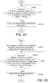
- an operating method for a portable electronic device is provided. Referring to FIG. 25 , a flowchart of an operating method for a portable electronic device is shown.
- the portable electronic device includes a body and an edge sensor disposed adjacent to an edge of the body.
- the operating method is described with the following steps.
- step S2501 a squeezing threshold and a releasing threshold are set.
- the squeezing threshold is higher than the releasing threshold.
- step S2502 whether a squeezing event is generated according to a sensed force of a squeeze action sensed by the edge sensor during a first time interval between a first time point and a second time point is determined. If yes, step S2503 is performed.
- step S2503 it is reported that the squeezing event is generated.
- the sensed force at the first time point reaches the squeezing threshold.
- the sensed force at the second time point reaches the releasing threshold.
- the second time point is later than the first time point, and the sensed force is higher than the releasing threshold during the first time period.
- an operating method for a portable electronic device is provided. Referring to FIG. 26 , a flowchart of an operating method for a portable electronic device is shown. The operating method is described with the following steps. In step S2601: it is determined that whether a portable electronic device is in a stationary state for a period of time. If yes, step S2602 is performed. In step S2602, an edge sensor of the portable electronic device is disabled.
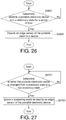
- an operating method for a portable electronic device is provided. Referring to FIG. 27 , a flowchart of an operating method for a portable electronic device is shown. The operating method is described with the following steps.
- step S2701 it is determined that whether a portable electronic device is changed from a stationary state to a non-stationary state. If yes, step S2702 is performed.
- step S2702 a squeezing event sensed by the edge sensor is ignored. The squeezing event occurs within a time period after the time point at which the non-stationary state of the portable electronic device starts.
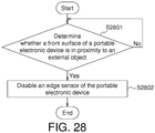
- an operating method for a portable electronic device is provided. Referring to FIG. 28 , a flowchart of an operating method for a portable electronic device is shown. The operating method is described with the following steps. In step S2801: it is determined that whether a front surface of a portable electronic device is in proximity to an external object. If yes, step S2802 is performed. In step S2802, an edge sensor of the portable electronic device is disabled.
- an operating method for a portable electronic device is provided. Referring to FIG. 31 , a flowchart of an operating method for a portable electronic device is shown.
- the portable electronic device comprises a body, a touch display screen and an edge sensor.
- the touch display screen is disposed on the body.
- the edge sensor is disposed adjacent to an edge of the body.
- the operating method is described with the following steps. In step S3101, it is determined that whether an event is detected by the edge sensor. If yes, step S3102 is performed. In step S3102, a touch function of the touch display screen is disabled. While the disclosure has been described by way of example and in terms of the exemplary embodiment(s), it is to be understood that the disclosure is not limited thereto. On the contrary, it is intended to cover various modifications and similar arrangements and procedures, and the scope of the appended claims therefore should be accorded the broadest interpretation so as to encompass all such modifications and similar arrangements and procedures.
Landscapes
- Engineering & Computer Science (AREA)
- Theoretical Computer Science (AREA)
- General Engineering & Computer Science (AREA)
- Physics & Mathematics (AREA)
- General Physics & Mathematics (AREA)
- Human Computer Interaction (AREA)
- Computer Hardware Design (AREA)
- User Interface Of Digital Computer (AREA)
- Telephone Function (AREA)
Claims (12)
- Un procédé de fonctionnement pour un dispositif électronique portable (100), le dispositif électronique portable comprenant un corps (103) et des capteurs de bord (40) disposés adjacents à des bords du corps du dispositif portable, sur un premier côté (S3) et un deuxième côté (S4) du corps, le premier côté (S3) étant opposé au deuxième côté (S4), le procédé de fonctionnement comprenant le fait :de déterminer si une première action de serrage captée par les capteurs de bord correspond à une action de serrage effective selon la force de la première action de serrage, un premier seuil de serrage (TH1), et un premier seuil de relâchement (TH2), où le premier seuil de relâchement (TH2) est plus petit que le premier seuil de serrage (TH1), le premier seuil de serrage (TH1) est configuré pour déterminer le début de l'action de serrage effective et le premier seuil de relâchement (TH2) est configuré pour déterminer la fin de l'action de serrage effective ; etde réaliser une fonction prédéfinie en réponse au fait de déterminer que la première action de serrage correspond à l'action de serrage effective ;où la force de la première action de serrage atteint le premier seuil de serrage (TH1) à un premier point dans le temps (TM2) et la force de la première action de serrage diminue jusqu'au premier seuil de relâchement (TH2) à un deuxième point dans le temps (TM3), où la fonction prédéfinie est réalisée selon une première période de temps (PT1) entre le premier point dans le temps (TM2) et le deuxième point dans le temps (TM3) et la première action de serrage correspond à l'action de serrage effective.
- Le procédé selon la revendication 1, où avant l'étape consistant à réaliser la fonction prédéfinie, le procédé comprend en sus le fait :de déterminer si la première période de temps (PT1) est plus grande qu'un premier seuil de temps ; etde déterminer que l'action de serrage effective correspond à une action de serrage longue en réponse au fait de déterminer que la première période est plus grande que le premier seuil de temps ;où la fonction prédéfinie réalisée est une première fonction prédéfinie en réponse au fait de déterminer que l'action de serrage effective correspond à l'action de serrage longue.
- Le procédé selon la revendication 2, où avant l'étape consistant à réaliser la fonction prédéfinie, le procédé comprend en sus le fait :de déterminer que l'action de serrage effective correspond à une action de serrage courte en réponse au fait de déterminer que la première période n'est pas plus grande que le premier seuil de temps ;où la fonction prédéfinie réalisée est une deuxième fonction prédéfinie en réponse au fait de déterminer que l'action de serrage effective correspond à l'action de serrage courte, et où la première fonction prédéfinie est différente de la deuxième fonction prédéfinie.
- Le procédé selon n'importe laquelle des revendications 1 à 3, comprenant en sus le fait :après avoir déterminé que la première action de serrage correspond à l'action effective, de déterminer si un intervalle de temps (PT2) entre la première action de serrage et une deuxième action de serrage captée par les capteurs de bord (40) est plus court qu'une valeur spécifique ; eten réponse au fait de déterminer que l'intervalle de temps est plus court qu'une valeur spécifique, de modifier le premier seuil de serrage (TH1) et le premier seuil de relâchement (TH2).
- Le procédé selon la revendication 4, où le premier seuil de serrage (TH1) est modifié en un deuxième seuil de serrage (TH1') et le premier seuil de relâchement (TH2) est modifié en un deuxième seuil de relâchement (TH2'), le deuxième seuil de serrage (TH1') est plus petit que le premier seuil de serrage (TH1) et le deuxième seuil de relâchement (TH2') est plus petit que le premier seuil de relâchement (TH2), le procédé comprend le fait :
de déterminer que la deuxième action de serrage correspond à une action de serrage effective selon la force de la deuxième action de serrage, le deuxième seuil de serrage (TH1'), et le deuxième seuil de relâchement (TH2'), où la force de la deuxième action de serrage atteint le deuxième seuil de serrage (TH1') à un troisième point dans le temps (TM5), et l'intervalle de temps est entre le deuxième point dans le temps et le troisième point dans le temps. - Le procédé selon n'importe laquelle des revendications 1 à 3, où après l'étape consistant à réaliser une fonction prédéfinie, le procédé comprend en sus le fait :de déterminer une valeur selon le premier seuil de serrage (TH1) et une courbe force-temps correspondant à la première action de serrage ; etde déterminer s'il convient de modifier le premier seuil de serrage (TH1) en comparant la valeur et une valeur prédéfinie.
- Le procédé selon la revendication 6, où la valeur est la valeur moyenne d'une aire définie par la courbe force-temps et le premier seuil de serrage (TH1), le procédé comprend en sus le fait :
de modifier le premier seuil de serrage (TH1) en un deuxième seuil de serrage (TH1') en réponse au fait de déterminer que la valeur est plus petite que la valeur prédéfinie, où le deuxième seuil de serrage (TH1') est plus petit que le premier seuil de serrage (TH1). - Le procédé selon la revendication 6, comprenant en sus le fait :
de modifier le premier seuil de serrage (TH1) en un troisième seuil de serrage (TH1") en réponse au fait de déterminer que la valeur est plus grande que la valeur prédéfinie, où le troisième seuil de serrage (TH1") est plus grand que le premier seuil de serrage (TH1). - Un support d'enregistrement lisible par ordinateur non transitoire pour stocker un ou plusieurs programmes, les un ou plusieurs programmes amenant un dispositif électronique portable selon la revendication 10 à réaliser le procédé selon n'importe laquelle des revendications 1 à 8 une fois les un ou plusieurs programmes chargés sur le dispositif électronique portable et exécutés.
- Un dispositif électronique portable (100), comprenant :un corps (103) ;un écran d'affichage tactile (109) disposé sur le corps ;des capteurs de bord (40) disposés adjacents à des bords du corps du dispositif électronique portable, sur un premier côté (S3) et sur un deuxième côté (S4) du corps, le premier côté (S3) étant opposé au deuxième côté (S4) ; etun processeur (102) couplé à l'écran d'affichage tactile et aux capteurs de bord,où le processeur est configuré pour :déterminer si une première action de serrage captée par les capteurs de bord correspond à une action de serrage effective selon la force de la première action de serrage, un premier seuil de serrage (TH1), et un premier seuil de relâchement (TH2), où le premier seuil de relâchement (TH2) est plus petit que le premier seuil de serrage (TH1), le premier seuil de serrage (TH1) est configuré pour déterminer le début de l'action de serrage effective et le premier seuil de relâchement (TH2) est configuré pour déterminer la fin de l'action de serrage effective ; etréaliser une fonction prédéfinie en réponse au fait de déterminer que la première action de serrage correspond à l'action de serrage effective ;où la force de la première action de serrage atteint le premier seuil de serrage (TH1) à un premier point dans le temps (TM2) et la force de la première action de serrage diminue jusqu'au premier seuil de relâchement (TH2) à un deuxième point dans le temps (TH3), où la fonction prédéfinie est réalisée selon une première période de temps (PT1) entre le premier point dans le temps (TM2) et le deuxième point dans le temps (TM3) et la première action de serrage correspond à l'action de serrage effective.
- Le dispositif électronique portable selon la revendication 10, où le processeur est en sus configuré pour :après avoir déterminé que la première action de serrage correspond à l'action effective, déterminer si un intervalle de temps (PT2) entre la première action de serrage et une deuxième action de serrage captée par les capteurs de bord est plus court qu'une valeur spécifique ; eten réponse au fait de déterminer que l'intervalle de temps est plus court qu'une valeur spécifique, modifier le premier seuil de serrage (TH1) et le premier seuil de relâchement (TH2).
- Le dispositif électronique portable selon la revendication 10, où le processeur est en sus configuré pour :déterminer une valeur selon le premier seuil de serrage (TH1) et une courbe force-temps correspondant à la première action de serrage ; etdéterminer s'il convient de modifier le premier seuil de serrage (TH1) en comparant la valeur et une valeur prédéfinie.
Priority Applications (1)
| Application Number | Priority Date | Filing Date | Title |
|---|---|---|---|
| EP20211093.8A EP3805910A1 (fr) | 2016-09-09 | 2017-09-08 | Dispositif électronique portable, procédé de fonctionnement correspondant et support d'enregistrement lisible par ordinateur non transitoire |
Applications Claiming Priority (4)
| Application Number | Priority Date | Filing Date | Title |
|---|---|---|---|
| US201662385924P | 2016-09-09 | 2016-09-09 | |
| US201762501784P | 2017-05-05 | 2017-05-05 | |
| US15/594,851 US10067668B2 (en) | 2016-09-09 | 2017-05-15 | Portable electronic device, operating method for the same, and non-transitory computer readable recording medium |
| EP17190150.7A EP3293622B1 (fr) | 2016-09-09 | 2017-09-08 | Dispositif électronique portable, procédé de fonctionnement correspondant et support d'enregistrement non transitoire lisible par ordinateur |
Related Parent Applications (2)
| Application Number | Title | Priority Date | Filing Date |
|---|---|---|---|
| EP17190150.7A Division EP3293622B1 (fr) | 2016-09-09 | 2017-09-08 | Dispositif électronique portable, procédé de fonctionnement correspondant et support d'enregistrement non transitoire lisible par ordinateur |
| EP17190150.7A Division-Into EP3293622B1 (fr) | 2016-09-09 | 2017-09-08 | Dispositif électronique portable, procédé de fonctionnement correspondant et support d'enregistrement non transitoire lisible par ordinateur |
Related Child Applications (2)
| Application Number | Title | Priority Date | Filing Date |
|---|---|---|---|
| EP20211093.8A Division-Into EP3805910A1 (fr) | 2016-09-09 | 2017-09-08 | Dispositif électronique portable, procédé de fonctionnement correspondant et support d'enregistrement lisible par ordinateur non transitoire |
| EP20211093.8A Division EP3805910A1 (fr) | 2016-09-09 | 2017-09-08 | Dispositif électronique portable, procédé de fonctionnement correspondant et support d'enregistrement lisible par ordinateur non transitoire |
Publications (2)
| Publication Number | Publication Date |
|---|---|
| EP3579095A1 EP3579095A1 (fr) | 2019-12-11 |
| EP3579095B1 true EP3579095B1 (fr) | 2021-05-26 |
Family
ID=59858551
Family Applications (4)
| Application Number | Title | Priority Date | Filing Date |
|---|---|---|---|
| EP20211093.8A Ceased EP3805910A1 (fr) | 2016-09-09 | 2017-09-08 | Dispositif électronique portable, procédé de fonctionnement correspondant et support d'enregistrement lisible par ordinateur non transitoire |
| EP17190150.7A Active EP3293622B1 (fr) | 2016-09-09 | 2017-09-08 | Dispositif électronique portable, procédé de fonctionnement correspondant et support d'enregistrement non transitoire lisible par ordinateur |
| EP19187612.7A Active EP3579095B1 (fr) | 2016-09-09 | 2017-09-08 | Dispositif électronique portable, procédé de fonctionnement correspondant et support d'enregistrement lisible par ordinateur non transitoire |
| EP18187190.6A Active EP3432130B1 (fr) | 2016-09-09 | 2017-09-08 | Dispositif électronique portable, procédé de fonctionnement correspondant et support d'enregistrement lisible par ordinateur non transitoire |
Family Applications Before (2)
| Application Number | Title | Priority Date | Filing Date |
|---|---|---|---|
| EP20211093.8A Ceased EP3805910A1 (fr) | 2016-09-09 | 2017-09-08 | Dispositif électronique portable, procédé de fonctionnement correspondant et support d'enregistrement lisible par ordinateur non transitoire |
| EP17190150.7A Active EP3293622B1 (fr) | 2016-09-09 | 2017-09-08 | Dispositif électronique portable, procédé de fonctionnement correspondant et support d'enregistrement non transitoire lisible par ordinateur |
Family Applications After (1)
| Application Number | Title | Priority Date | Filing Date |
|---|---|---|---|
| EP18187190.6A Active EP3432130B1 (fr) | 2016-09-09 | 2017-09-08 | Dispositif électronique portable, procédé de fonctionnement correspondant et support d'enregistrement lisible par ordinateur non transitoire |
Country Status (2)
| Country | Link |
|---|---|
| US (1) | US10067668B2 (fr) |
| EP (4) | EP3805910A1 (fr) |
Families Citing this family (6)
| Publication number | Priority date | Publication date | Assignee | Title |
|---|---|---|---|---|
| KR102561736B1 (ko) * | 2016-06-01 | 2023-08-02 | 삼성전자주식회사 | 터치 디스플레이를 가지는 전자 장치 및 이의 지문을 이용한 기능 실행 방법 |
| WO2019158618A1 (fr) * | 2018-02-16 | 2019-08-22 | Koninklijke Philips N.V. | Affichage et activation ergonomiques dans un dispositif d'imagerie médicale à ultrasons portatif |
| US10831290B2 (en) * | 2019-02-22 | 2020-11-10 | Qualcomm Incorporated | Stylus-tracking piezoelectric sensor |
| CN111443863A (zh) * | 2020-04-07 | 2020-07-24 | Oppo广东移动通信有限公司 | 页面操控方法、装置、存储介质及终端 |
| FI20225387A1 (en) * | 2022-05-04 | 2023-11-05 | Ai2Ai Oy | Interaction device |
| US12236954B1 (en) * | 2024-02-28 | 2025-02-25 | Justin Benjamin Weiss | Speech enabling system |
Family Cites Families (16)
| Publication number | Priority date | Publication date | Assignee | Title |
|---|---|---|---|---|
| US7800592B2 (en) * | 2005-03-04 | 2010-09-21 | Apple Inc. | Hand held electronic device with multiple touch sensing devices |
| KR100474724B1 (ko) * | 2001-08-04 | 2005-03-08 | 삼성전자주식회사 | 터치스크린을 가지는 장치 및 그 장치에 외부디스플레이기기를 연결하여 사용하는 방법 |
| US8780054B2 (en) * | 2008-09-26 | 2014-07-15 | Lg Electronics Inc. | Mobile terminal and control method thereof |
| US8432368B2 (en) * | 2010-01-06 | 2013-04-30 | Qualcomm Incorporated | User interface methods and systems for providing force-sensitive input |
| US8890823B2 (en) * | 2012-01-09 | 2014-11-18 | Motorola Mobility Llc | System and method for reducing occurrences of unintended operations in an electronic device |
| US20130300668A1 (en) | 2012-01-17 | 2013-11-14 | Microsoft Corporation | Grip-Based Device Adaptations |
| KR101995486B1 (ko) * | 2012-06-26 | 2019-07-02 | 엘지전자 주식회사 | 이동 단말기 및 그것의 제어 방법 |
| KR101885655B1 (ko) * | 2012-10-29 | 2018-09-10 | 엘지전자 주식회사 | 이동 단말기 |
| US10078365B2 (en) * | 2013-04-19 | 2018-09-18 | Lg Electronics Inc. | Device for controlling mobile terminal and method of controlling the mobile terminal |
| KR20140135400A (ko) * | 2013-05-16 | 2014-11-26 | 삼성전자주식회사 | 이동 단말기 및 그 제어 방법 |
| EP2816442B1 (fr) * | 2013-06-20 | 2019-07-31 | Samsung Electronics Co., Ltd | Dispositif électronique et procédé de commande de dispositif électronique au moyen de détection de saisie |
| US20150160849A1 (en) * | 2013-12-06 | 2015-06-11 | Microsoft Corporation | Bezel Gesture Techniques |
| EP2905679B1 (fr) * | 2014-01-07 | 2018-08-22 | Samsung Electronics Co., Ltd | Dispositif électronique et procédé de contrôle dudit dispositif |
| KR20160013760A (ko) * | 2014-07-28 | 2016-02-05 | 삼성전자주식회사 | 터치 신호를 이용한 디바이스에 대한 압력 측정 방법 및 압력을 측정하는 디바이스 |
| KR102298972B1 (ko) | 2014-10-21 | 2021-09-07 | 삼성전자 주식회사 | 전자 장치의 엣지에서 수행되는 제스처를 기반으로 하는 동작 수행 |
| KR102332015B1 (ko) * | 2015-02-26 | 2021-11-29 | 삼성전자주식회사 | 터치 처리 방법 및 이를 지원하는 전자 장치 |
-
2017
- 2017-05-15 US US15/594,851 patent/US10067668B2/en active Active
- 2017-09-08 EP EP20211093.8A patent/EP3805910A1/fr not_active Ceased
- 2017-09-08 EP EP17190150.7A patent/EP3293622B1/fr active Active
- 2017-09-08 EP EP19187612.7A patent/EP3579095B1/fr active Active
- 2017-09-08 EP EP18187190.6A patent/EP3432130B1/fr active Active
Also Published As
| Publication number | Publication date |
|---|---|
| EP3432130B1 (fr) | 2020-06-24 |
| EP3579095A1 (fr) | 2019-12-11 |
| EP3293622A1 (fr) | 2018-03-14 |
| EP3432130A1 (fr) | 2019-01-23 |
| US10067668B2 (en) | 2018-09-04 |
| EP3293622B1 (fr) | 2019-10-23 |
| US20180074692A1 (en) | 2018-03-15 |
| EP3805910A1 (fr) | 2021-04-14 |
Similar Documents
| Publication | Publication Date | Title |
|---|---|---|
| EP3579095B1 (fr) | Dispositif électronique portable, procédé de fonctionnement correspondant et support d'enregistrement lisible par ordinateur non transitoire | |
| US20250251799A1 (en) | Devices, Methods, and Graphical User Interfaces for Providing Haptic Feedback | |
| US10664092B2 (en) | Portable electronic device, operating method for the same, and non-transitory computer readable recording medium | |
| KR102664705B1 (ko) | 복수의 카메라들을 이용하여 이미지의 배율을 변경하기 위한 전자 장치 및 방법 | |
| US20200371630A1 (en) | Devices and Methods for Processing and Disambiguating Touch Inputs Using Intensity Thresholds Based on Prior Input Intensity | |
| US9104288B2 (en) | Method and apparatus for providing quick access to media functions from a locked screen | |
| CN107395969B (zh) | 一种拍摄方法及移动终端 | |
| CN107124508B (zh) | 悬浮控件的位置调整方法、装置及终端、可读存储介质 | |
| CN113821134B (zh) | 控制光标移动的方法、内容选择方法、控制页面滚动的方法及电子设备 | |
| US20150301595A1 (en) | Electronic apparatus and eye-gaze input method | |
| TWI692705B (zh) | 可攜式電子裝置、及其操作方法、與使用此方法之記錄媒體 | |
| CN108704308A (zh) | 射击游戏的控制方法、装置、存储介质和电子设备 | |
| WO2018107897A1 (fr) | Procédé et dispositif de commande d'écran tactile, terminal mobile et support de stockage | |
| CN104395851A (zh) | 用于通过检测显示器的覆盖区域来管理电子装置上的内容的显示的系统和方法 | |
| CN110351424A (zh) | 手势交互方法和终端 | |
| WO2012164170A1 (fr) | Procédé et appareil pour indiquer des notifications de manière spatiale | |
| WO2017161803A1 (fr) | Procédé et terminal de réglage de paramètres | |
| WO2018068328A1 (fr) | Terminal et procédé d'affichage d'interface | |
| CN110442263A (zh) | 触控显示屏处理方法、装置、存储介质及电子设备 | |
| CN108984092B (zh) | 设备控制方法、装置、存储介质及电子设备 | |
| US20150193051A1 (en) | Touch system and touch-detecting method thereof | |
| CN108704307A (zh) | 触控信息的处理方法、装置、存储介质及电子装置 | |
| US11556173B2 (en) | Electronic apparatus, method for controlling the same, and storage medium | |
| US20170277417A1 (en) | Method for Adjusting Setting and Terminal | |
| EP2897034A1 (fr) | Procédé, système, dispositif électronique et dispositif périphérique de communication |
Legal Events
| Date | Code | Title | Description |
|---|---|---|---|
| PUAI | Public reference made under article 153(3) epc to a published international application that has entered the european phase |
Free format text: ORIGINAL CODE: 0009012 |
|
| STAA | Information on the status of an ep patent application or granted ep patent |
Free format text: STATUS: REQUEST FOR EXAMINATION WAS MADE |
|
| 17P | Request for examination filed |
Effective date: 20190722 |
|
| AC | Divisional application: reference to earlier application |
Ref document number: 3293622 Country of ref document: EP Kind code of ref document: P |
|
| AK | Designated contracting states |
Kind code of ref document: A1 Designated state(s): AL AT BE BG CH CY CZ DE DK EE ES FI FR GB GR HR HU IE IS IT LI LT LU LV MC MK MT NL NO PL PT RO RS SE SI SK SM TR |
|
| RBV | Designated contracting states (corrected) |
Designated state(s): AL AT BE BG CH CY CZ DE DK EE ES FI FR GB GR HR HU IE IS IT LI LT LU LV MC MK MT NL NO PL PT RO RS SE SI SK SM TR |
|
| GRAP | Despatch of communication of intention to grant a patent |
Free format text: ORIGINAL CODE: EPIDOSNIGR1 |
|
| STAA | Information on the status of an ep patent application or granted ep patent |
Free format text: STATUS: GRANT OF PATENT IS INTENDED |
|
| INTG | Intention to grant announced |
Effective date: 20200921 |
|
| GRAJ | Information related to disapproval of communication of intention to grant by the applicant or resumption of examination proceedings by the epo deleted |
Free format text: ORIGINAL CODE: EPIDOSDIGR1 |
|
| STAA | Information on the status of an ep patent application or granted ep patent |
Free format text: STATUS: REQUEST FOR EXAMINATION WAS MADE |
|
| INTC | Intention to grant announced (deleted) | ||
| GRAP | Despatch of communication of intention to grant a patent |
Free format text: ORIGINAL CODE: EPIDOSNIGR1 |
|
| STAA | Information on the status of an ep patent application or granted ep patent |
Free format text: STATUS: GRANT OF PATENT IS INTENDED |
|
| INTG | Intention to grant announced |
Effective date: 20210114 |
|
| GRAS | Grant fee paid |
Free format text: ORIGINAL CODE: EPIDOSNIGR3 |
|
| GRAA | (expected) grant |
Free format text: ORIGINAL CODE: 0009210 |
|
| STAA | Information on the status of an ep patent application or granted ep patent |
Free format text: STATUS: THE PATENT HAS BEEN GRANTED |
|
| AC | Divisional application: reference to earlier application |
Ref document number: 3293622 Country of ref document: EP Kind code of ref document: P |
|
| AK | Designated contracting states |
Kind code of ref document: B1 Designated state(s): AL AT BE BG CH CY CZ DE DK EE ES FI FR GB GR HR HU IE IS IT LI LT LU LV MC MK MT NL NO PL PT RO RS SE SI SK SM TR |
|
| REG | Reference to a national code |
Ref country code: GB Ref legal event code: FG4D |
|
| REG | Reference to a national code |
Ref country code: CH Ref legal event code: EP |
|
| REG | Reference to a national code |
Ref country code: DE Ref legal event code: R096 Ref document number: 602017039513 Country of ref document: DE |
|
| REG | Reference to a national code |
Ref country code: AT Ref legal event code: REF Ref document number: 1396884 Country of ref document: AT Kind code of ref document: T Effective date: 20210615 |
|
| REG | Reference to a national code |
Ref country code: IE Ref legal event code: FG4D |
|
| REG | Reference to a national code |
Ref country code: NL Ref legal event code: FP |
|
| REG | Reference to a national code |
Ref country code: LT Ref legal event code: MG9D |
|
| REG | Reference to a national code |
Ref country code: AT Ref legal event code: MK05 Ref document number: 1396884 Country of ref document: AT Kind code of ref document: T Effective date: 20210526 |
|
| PG25 | Lapsed in a contracting state [announced via postgrant information from national office to epo] |
Ref country code: HR Free format text: LAPSE BECAUSE OF FAILURE TO SUBMIT A TRANSLATION OF THE DESCRIPTION OR TO PAY THE FEE WITHIN THE PRESCRIBED TIME-LIMIT Effective date: 20210526 Ref country code: LT Free format text: LAPSE BECAUSE OF FAILURE TO SUBMIT A TRANSLATION OF THE DESCRIPTION OR TO PAY THE FEE WITHIN THE PRESCRIBED TIME-LIMIT Effective date: 20210526 Ref country code: FI Free format text: LAPSE BECAUSE OF FAILURE TO SUBMIT A TRANSLATION OF THE DESCRIPTION OR TO PAY THE FEE WITHIN THE PRESCRIBED TIME-LIMIT Effective date: 20210526 Ref country code: BG Free format text: LAPSE BECAUSE OF FAILURE TO SUBMIT A TRANSLATION OF THE DESCRIPTION OR TO PAY THE FEE WITHIN THE PRESCRIBED TIME-LIMIT Effective date: 20210826 Ref country code: AT Free format text: LAPSE BECAUSE OF FAILURE TO SUBMIT A TRANSLATION OF THE DESCRIPTION OR TO PAY THE FEE WITHIN THE PRESCRIBED TIME-LIMIT Effective date: 20210526 |
|
| PG25 | Lapsed in a contracting state [announced via postgrant information from national office to epo] |
Ref country code: LV Free format text: LAPSE BECAUSE OF FAILURE TO SUBMIT A TRANSLATION OF THE DESCRIPTION OR TO PAY THE FEE WITHIN THE PRESCRIBED TIME-LIMIT Effective date: 20210526 Ref country code: NO Free format text: LAPSE BECAUSE OF FAILURE TO SUBMIT A TRANSLATION OF THE DESCRIPTION OR TO PAY THE FEE WITHIN THE PRESCRIBED TIME-LIMIT Effective date: 20210826 Ref country code: PL Free format text: LAPSE BECAUSE OF FAILURE TO SUBMIT A TRANSLATION OF THE DESCRIPTION OR TO PAY THE FEE WITHIN THE PRESCRIBED TIME-LIMIT Effective date: 20210526 Ref country code: RS Free format text: LAPSE BECAUSE OF FAILURE TO SUBMIT A TRANSLATION OF THE DESCRIPTION OR TO PAY THE FEE WITHIN THE PRESCRIBED TIME-LIMIT Effective date: 20210526 Ref country code: PT Free format text: LAPSE BECAUSE OF FAILURE TO SUBMIT A TRANSLATION OF THE DESCRIPTION OR TO PAY THE FEE WITHIN THE PRESCRIBED TIME-LIMIT Effective date: 20210927 Ref country code: SE Free format text: LAPSE BECAUSE OF FAILURE TO SUBMIT A TRANSLATION OF THE DESCRIPTION OR TO PAY THE FEE WITHIN THE PRESCRIBED TIME-LIMIT Effective date: 20210526 Ref country code: GR Free format text: LAPSE BECAUSE OF FAILURE TO SUBMIT A TRANSLATION OF THE DESCRIPTION OR TO PAY THE FEE WITHIN THE PRESCRIBED TIME-LIMIT Effective date: 20210827 Ref country code: IS Free format text: LAPSE BECAUSE OF FAILURE TO SUBMIT A TRANSLATION OF THE DESCRIPTION OR TO PAY THE FEE WITHIN THE PRESCRIBED TIME-LIMIT Effective date: 20210926 |
|
| PG25 | Lapsed in a contracting state [announced via postgrant information from national office to epo] |
Ref country code: EE Free format text: LAPSE BECAUSE OF FAILURE TO SUBMIT A TRANSLATION OF THE DESCRIPTION OR TO PAY THE FEE WITHIN THE PRESCRIBED TIME-LIMIT Effective date: 20210526 Ref country code: ES Free format text: LAPSE BECAUSE OF FAILURE TO SUBMIT A TRANSLATION OF THE DESCRIPTION OR TO PAY THE FEE WITHIN THE PRESCRIBED TIME-LIMIT Effective date: 20210526 Ref country code: SK Free format text: LAPSE BECAUSE OF FAILURE TO SUBMIT A TRANSLATION OF THE DESCRIPTION OR TO PAY THE FEE WITHIN THE PRESCRIBED TIME-LIMIT Effective date: 20210526 Ref country code: DK Free format text: LAPSE BECAUSE OF FAILURE TO SUBMIT A TRANSLATION OF THE DESCRIPTION OR TO PAY THE FEE WITHIN THE PRESCRIBED TIME-LIMIT Effective date: 20210526 Ref country code: CZ Free format text: LAPSE BECAUSE OF FAILURE TO SUBMIT A TRANSLATION OF THE DESCRIPTION OR TO PAY THE FEE WITHIN THE PRESCRIBED TIME-LIMIT Effective date: 20210526 Ref country code: RO Free format text: LAPSE BECAUSE OF FAILURE TO SUBMIT A TRANSLATION OF THE DESCRIPTION OR TO PAY THE FEE WITHIN THE PRESCRIBED TIME-LIMIT Effective date: 20210526 Ref country code: SM Free format text: LAPSE BECAUSE OF FAILURE TO SUBMIT A TRANSLATION OF THE DESCRIPTION OR TO PAY THE FEE WITHIN THE PRESCRIBED TIME-LIMIT Effective date: 20210526 |
|
| REG | Reference to a national code |
Ref country code: DE Ref legal event code: R097 Ref document number: 602017039513 Country of ref document: DE |
|
| PLBE | No opposition filed within time limit |
Free format text: ORIGINAL CODE: 0009261 |
|
| STAA | Information on the status of an ep patent application or granted ep patent |
Free format text: STATUS: NO OPPOSITION FILED WITHIN TIME LIMIT |
|
| REG | Reference to a national code |
Ref country code: CH Ref legal event code: PL |
|
| 26N | No opposition filed |
Effective date: 20220301 |
|
| REG | Reference to a national code |
Ref country code: BE Ref legal event code: MM Effective date: 20210930 |
|
| PG25 | Lapsed in a contracting state [announced via postgrant information from national office to epo] |
Ref country code: IS Free format text: LAPSE BECAUSE OF FAILURE TO SUBMIT A TRANSLATION OF THE DESCRIPTION OR TO PAY THE FEE WITHIN THE PRESCRIBED TIME-LIMIT Effective date: 20210926 Ref country code: MC Free format text: LAPSE BECAUSE OF FAILURE TO SUBMIT A TRANSLATION OF THE DESCRIPTION OR TO PAY THE FEE WITHIN THE PRESCRIBED TIME-LIMIT Effective date: 20210526 Ref country code: AL Free format text: LAPSE BECAUSE OF FAILURE TO SUBMIT A TRANSLATION OF THE DESCRIPTION OR TO PAY THE FEE WITHIN THE PRESCRIBED TIME-LIMIT Effective date: 20210526 |
|
| PG25 | Lapsed in a contracting state [announced via postgrant information from national office to epo] |
Ref country code: LU Free format text: LAPSE BECAUSE OF NON-PAYMENT OF DUE FEES Effective date: 20210908 Ref country code: IT Free format text: LAPSE BECAUSE OF FAILURE TO SUBMIT A TRANSLATION OF THE DESCRIPTION OR TO PAY THE FEE WITHIN THE PRESCRIBED TIME-LIMIT Effective date: 20210526 Ref country code: IE Free format text: LAPSE BECAUSE OF NON-PAYMENT OF DUE FEES Effective date: 20210908 Ref country code: BE Free format text: LAPSE BECAUSE OF NON-PAYMENT OF DUE FEES Effective date: 20210930 |
|
| PG25 | Lapsed in a contracting state [announced via postgrant information from national office to epo] |
Ref country code: LI Free format text: LAPSE BECAUSE OF NON-PAYMENT OF DUE FEES Effective date: 20210930 Ref country code: CH Free format text: LAPSE BECAUSE OF NON-PAYMENT OF DUE FEES Effective date: 20210930 |
|
| REG | Reference to a national code |
Ref country code: DE Ref legal event code: R082 Ref document number: 602017039513 Country of ref document: DE Representative=s name: WAGNER & GEYER PARTNERSCHAFT MBB PATENT- UND R, DE |
|
| PG25 | Lapsed in a contracting state [announced via postgrant information from national office to epo] |
Ref country code: CY Free format text: LAPSE BECAUSE OF FAILURE TO SUBMIT A TRANSLATION OF THE DESCRIPTION OR TO PAY THE FEE WITHIN THE PRESCRIBED TIME-LIMIT Effective date: 20210526 |
|
| P01 | Opt-out of the competence of the unified patent court (upc) registered |
Effective date: 20230602 |
|
| PG25 | Lapsed in a contracting state [announced via postgrant information from national office to epo] |
Ref country code: HU Free format text: LAPSE BECAUSE OF FAILURE TO SUBMIT A TRANSLATION OF THE DESCRIPTION OR TO PAY THE FEE WITHIN THE PRESCRIBED TIME-LIMIT; INVALID AB INITIO Effective date: 20170908 |
|
| PG25 | Lapsed in a contracting state [announced via postgrant information from national office to epo] |
Ref country code: MK Free format text: LAPSE BECAUSE OF FAILURE TO SUBMIT A TRANSLATION OF THE DESCRIPTION OR TO PAY THE FEE WITHIN THE PRESCRIBED TIME-LIMIT Effective date: 20210526 |
|
| PG25 | Lapsed in a contracting state [announced via postgrant information from national office to epo] |
Ref country code: TR Free format text: LAPSE BECAUSE OF FAILURE TO SUBMIT A TRANSLATION OF THE DESCRIPTION OR TO PAY THE FEE WITHIN THE PRESCRIBED TIME-LIMIT Effective date: 20210526 |
|
| PG25 | Lapsed in a contracting state [announced via postgrant information from national office to epo] |
Ref country code: MT Free format text: LAPSE BECAUSE OF FAILURE TO SUBMIT A TRANSLATION OF THE DESCRIPTION OR TO PAY THE FEE WITHIN THE PRESCRIBED TIME-LIMIT Effective date: 20210526 |
|
| PGFP | Annual fee paid to national office [announced via postgrant information from national office to epo] |
Ref country code: NL Payment date: 20250704 Year of fee payment: 9 |
|
| PGFP | Annual fee paid to national office [announced via postgrant information from national office to epo] |
Ref country code: DE Payment date: 20250702 Year of fee payment: 9 |
|
| PGFP | Annual fee paid to national office [announced via postgrant information from national office to epo] |
Ref country code: GB Payment date: 20250703 Year of fee payment: 9 |
|
| PGFP | Annual fee paid to national office [announced via postgrant information from national office to epo] |
Ref country code: FR Payment date: 20250703 Year of fee payment: 9 |