EP3579206A1 - Gehäuse einer alarmanlage und alarmperipherievorrichtung davon - Google Patents
Gehäuse einer alarmanlage und alarmperipherievorrichtung davon Download PDFInfo
- Publication number
- EP3579206A1 EP3579206A1 EP18175917.6A EP18175917A EP3579206A1 EP 3579206 A1 EP3579206 A1 EP 3579206A1 EP 18175917 A EP18175917 A EP 18175917A EP 3579206 A1 EP3579206 A1 EP 3579206A1
- Authority
- EP
- European Patent Office
- Prior art keywords
- enclosure
- actuator unit
- base plate
- enclosure according
- tamper
- Prior art date
- Legal status (The legal status is an assumption and is not a legal conclusion. Google has not performed a legal analysis and makes no representation as to the accuracy of the status listed.)
- Withdrawn
Links
Images



Classifications
-
- G—PHYSICS
- G08—SIGNALLING
- G08B—SIGNALLING SYSTEMS, e.g. PERSONAL CALLING SYSTEMS; ORDER TELEGRAPHS; ALARM SYSTEMS
- G08B13/00—Burglar, theft or intruder alarms
- G08B13/02—Mechanical actuation
- G08B13/08—Mechanical actuation by opening, e.g. of door, of window, of drawer, of shutter, of curtain, of blind
-
- G—PHYSICS
- G08—SIGNALLING
- G08B—SIGNALLING SYSTEMS, e.g. PERSONAL CALLING SYSTEMS; ORDER TELEGRAPHS; ALARM SYSTEMS
- G08B13/00—Burglar, theft or intruder alarms
- G08B13/02—Mechanical actuation
- G08B13/12—Mechanical actuation by the breaking or disturbance of stretched cords or wires
- G08B13/126—Mechanical actuation by the breaking or disturbance of stretched cords or wires for a housing, e.g. a box, a safe, or a room
-
- G—PHYSICS
- G08—SIGNALLING
- G08B—SIGNALLING SYSTEMS, e.g. PERSONAL CALLING SYSTEMS; ORDER TELEGRAPHS; ALARM SYSTEMS
- G08B13/00—Burglar, theft or intruder alarms
- G08B13/02—Mechanical actuation
- G08B13/14—Mechanical actuation by lifting or attempted removal of hand-portable articles
- G08B13/1445—Mechanical actuation by lifting or attempted removal of hand-portable articles with detection of interference with a cable tethering an article, e.g. alarm activated by detecting detachment of article, breaking or stretching of cable
- G08B13/1463—Physical arrangements, e.g. housings
-
- G—PHYSICS
- G08—SIGNALLING
- G08B—SIGNALLING SYSTEMS, e.g. PERSONAL CALLING SYSTEMS; ORDER TELEGRAPHS; ALARM SYSTEMS
- G08B29/00—Checking or monitoring of signalling or alarm systems; Prevention or correction of operating errors, e.g. preventing unauthorised operation
- G08B29/02—Monitoring continuously signalling or alarm systems
- G08B29/04—Monitoring of the detection circuits
- G08B29/046—Monitoring of the detection circuits prevention of tampering with detection circuits
-
- G—PHYSICS
- G08—SIGNALLING
- G08B—SIGNALLING SYSTEMS, e.g. PERSONAL CALLING SYSTEMS; ORDER TELEGRAPHS; ALARM SYSTEMS
- G08B29/00—Checking or monitoring of signalling or alarm systems; Prevention or correction of operating errors, e.g. preventing unauthorised operation
- G08B29/02—Monitoring continuously signalling or alarm systems
- G08B29/06—Monitoring of the line circuits, e.g. signalling of line faults
- G08B29/08—Signalling of tampering with the line circuit
Definitions
- the present invention relates to an enclosure of an alarm system, having an anti-tamper detection system, and to an alarm peripheral thereof.
- Alarm systems of different kinds are today widely known and used in private homes, working facilities and building complexes to prevent break-ins and to protect the owner's properties.
- a commonly used feature in an alarm system is some kind of tamper detector which can signal an attempt to tamper with e.g. a central unit and trigger an alarm.
- An example of an alarm system using a tamper detector is disclosed in WO 2007/021729 A2 .
- An object of the present invention is to provide improvements over prior art. This object is achieved by an invention defined in the appended independent claims; certain embodiments being set forth in the related dependent claims.
- an enclosure for an alarm peripheral including a base plate, arranged to be mounted to a mounting surface, and an actuator unit.
- the actuator unit is arranged to be independently mounted to the mounting surface.
- the enclosure further includes an anti-tamper detection system comprising a first element associated with the actuator unit and a second element associated with the base plate, such that when the enclosure is mounted to the mounting surface, the anti-tamper detection system is arranged to detect a relative movement between the first and second elements.
- an electronic device for an alarm system comprising a wall bracket having a base plate configured to be mounted to a surface, and a tamper unit.
- the tamper unit is mounted to the surface separated from the base plate of the wall bracket.
- the tamper unit comprises actuator means, arranged in connection with tamper detector means of the electronic device during a mounted state, where the tamper detector means is configured to detect movements of the electronic device in relation to the actuator means during the mounted state.
- an alarm peripheral including at least one enclosure as described above.
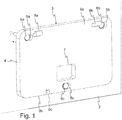
- an enclosure 1 of an electronic device 1 and some parts of the electronic device are illustrated.
- the enclosure 1 as illustrated and described is intended to be used in an alarm system, e.g. a home security system or the like.
- the enclosure 1, which could be for, for example, a central unit device, a key pad device, a display device or any other alarm peripheral, is often mounted to an inner surface 2 of a building, such as a wall surface or a door surface, in the illustrating drawings the surface is a wall surface 2.
- the enclosure 1 includes a wall bracket 3 to which a front cover 25, housing the rest of the components of the electronic device, is detachably mounted to.
- the wall bracket 3 is configured to mount the enclosure 1 to the chosen surface 2.
- the wall bracket 3 includes a base plate 4 which has at least a first, substantially flat, surface facing the wall surface 2 in its mounted state. It also has several mounting apertures 5a-c in which screws or other fastening means 6a-c can be received when mounting the wall bracket 3 to the wall surface 2.
- the wall bracket includes an opening 7 in its base plate 4 which is configured and designed to receive an actuator unit 10 of an anti-tamper detection system of the electronic device. The opening 7 is located away from the edges of the base plate 4.
- the shape and size of the opening 7 is, in the illustrated embodiment, as close to the shape and size of the actuator unit 10 as possible.
- the opening 7 can be used as a guide when mounting the actuator unit 10 to the wall surface 2 or the actuator unit 10 can be used as a guide when mounting the base plate 4 of the wall bracket 3 to the wall surface 2. This is advantageous and will secure the installation of the enclosure 1 to the surface 2 such that all the components of the electronic device are arranged at their intended location, thus securing the operation of the electronic device, and especially the operation of the anti-tampering function.
- the wall bracket 3 includes three attachment means 8a-c, for attaching a, later described, front cover 25 of the enclosure 1 to the wall bracket 3.
- the first two attachment means 8a-b arranged in an upper portion 9a of the wall bracket 3, are shaped such that they allow the front cover 25 to be hooked to the upper portion 9a of the wall bracket 3.
- the third attachment means 8c is arranged at a bottom rim portion 9b.
- the third attachment means is, in the illustrated embodiment an opening 8c for receiving fastening means, such as a screw, in order to secure the front cover 25 to the wall bracket 3 once the front cover 25 is hooked to the first two attachment means 8a-b.
- Alternative attachment means such as screws, glue or snap-in attachments to name a few, are of course possible when attaching the front cover to the wall bracket.
- the enclosure 1 further includes the above presented actuator unit 10, see Figs 3 and 4 , having a first element of the anti-tamper detection system, from now on called actuator means 12, arranged in connection with and configured to affect a second element of the anti-tamper detection system, from now on called tamper detector means 17, arranged in the enclosure 1.
- the actuator means 12 and the tamper detector means 17 are related such that, movements of the enclosure 1 in relation to the actuator means 12 of the independently mounted actuator unit 10 are being detected by the tamper detector means 17.
- the purpose of this anti-tamper detection system is to, when the enclosure is mounted to the mounting surface, in the illustrated embodiment the wall surface 2, the anti-tamper detection system is arranged to detect a relative movement between the first and second elements.
- Figs 9 and 10 Arranged in connection with could mean that the actuator means and the tamper detector means are either in contact with each other or, as is illustrated in the drawings, arranged at a distance from each other.
- the distance between the actuator means and the tamper detector means depends on features of the respective means, for example witch type of sensor or mechanical switch is used, or if a magnet has been chosen for the purpose.
- the actuator unit 10 further has a base portion 13 which is mounted flush with the base plate 4 of the wall bracket 3 on the wall surface 2 by means of mounting means 14, such as a screw or similar.
- the mounting means 14 is received in a mounting aperture 15 of the base portion 13 of the actuator unit 10.
- the location of the mounted actuator unit 10 is in the opening 7 of the wall bracket 3 but separated from the wall bracket 3, i.e. not attached to the wall bracket 3 as it is mounted with its own mounting means 14 or mounted to the wall independently of the wall bracket 3. A person trying to tamper with the enclosure 1 will not be able to reach the actuator unit 10 as it is located, in the opening 7 of the wall bracket, away from the edges of the wall bracket 3.
- a known example of an attached tamper detector is an alarm device having a break-off feature by means of a brittle conductive adhesive which is configured to break if someone is trying to tamper with the device.
- These attachments between the tamper detector and the device could be affected by a porous wall and not work as desired.
- the actuator unit since the actuator unit is not affected by the wall bracket and the tampering of the enclosure, a secure and reliable anti-tamper function is achieved. At the same time, the actuator unit is protected by the wall bracket and the enclosure, as explained above, making it very difficult to tamper with the actuator unit itself.
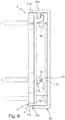
- the actuator means 12 is biased and in connection with the tamper detector means 17 of the enclosure 1 in the mounted state, see Fig. 8 , such that the tamper detector means 17 is able to detect movements of the enclosure 1, in relation to the actuator means 12, away from the wall surface 2 and the actuator means 12.
- the actuator means 12 is arranged with a spring 18 which in turn is at least partly arranged in a spring recess 19 of the base portion 13.
- the actuator means 12 has a bottom portion 20a and a top portion 20b, where the bottom portion 20a is arranged inside the coil of the spring 18 and the top portion 20b is arranged outside of the spring 18, facing the front cover 25 and the tamper detector means 17 when mounted.
- the top portion 20b may be provided with trigger means 21, such as a magnet, a shape/protrusion or a material of any suitable type.
- the trigger means 21 is configured to affect the tamper detector means 17, which in turn can be a magnet, a sensor or a mechanical switch of any suitable type.
- the tamper detector means 17 is configured to detect the movement of the enclosure 1, especially a movement of the enclosure away from the actuator unit 10, by triggering a change in the relationship between the trigger means 21 and the tamper detector means 17, for example a change in distance between the two, or a break in their magnetic connection.
- the trigger means is a metal plate 21 and the tamper detector means 17 comprises a metal detector configured to sense the presence of the metal plate 21 of the trigger means.
- the trigger means may be a flat surface and the tamper detector means may comprise a range sensor measuring the distance between the two.
- the trigger means and components of the tamper detector means may however be chosen from a group of any suitable means in order to achieve the detection function.
- the tamper detector means 17 is integrated in a PCB (Printed Circuit Board) 22 being a part of the anti-tamper detection system, configured to send a tampering signal to either the enclosure 1 or to any other suitable alarm peripheral for signaling that someone is trying to tamper with the enclosure 1.
- the actuator means 12 and the tamper detector means 17 are, when mounted, in a non-tampering state in connection with each other. Sometimes they can even be in contact with each other, which is the case if for example the trigger means and the tamper detector means comprise corresponding magnets (not shown).
- the first element 12, the actuator means, is associated with the actuator unit 10 and a second element 17, the tamper detector means, is associated with the base plate 4, as the base plate 4 and the front cover 25 are attached to each other, or if the base plate is an integrated part of the front cover, which is possible in an alternative embodiments.
- the anti-tamper detection system is arranged to detect a relative movement between the first and second elements.
- the enclosure 1 further comprises, which has been previously presented, a front cover 25, configured to house the remaining parts of the electronic device including the tamper detector means 17.
- the remaining parts could for example be the PCB (Printed Circuit Board) 22, transmitting/receiving means, or any other suitable means for an electronic device.
- attachment means 30a-b On an inner top surface 27 or a top rim portion 28a of the front cover 25 there is provided attachment means 30a-b corresponding to the attachment means 8a-b arranged in the top portion 9a of the wall bracket 3.
- the aperture in the bottom rim portion 28b corresponds to the third attachment means 8c of the wall bracket 3.
- the third attachment means 8c is configured to lock and secure the attachment of the front cover 25 to the wall bracket 3. Further attachment means for creating an even more secure and tight mounting between the front cover 25 and the wall bracket 3 is of course possible.
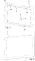
- Fig. 5 illustrates an inside of the front cover 25 while Fig. 6 illustrates an outside of the front cover 25 and what the enclosure 1 would look like in the mounted state.
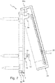
- Figs 7 and 8 illustrate how to mount the front cover 25 to the wall bracket 3 and how the actuator means 12 is placed to connect to the tamper detector means 17.
- the front cover 25 is by means of its attachment means 30a-b hooked to the attachment means 8a-b of the wall bracket 3. It is then folded towards the wall bracket 3 such that the front cover 25, in the mounted state, substantially encloses the wall bracket 3, thus protecting both the wall bracket 3 and the actuator unit 10.
- the front cover 25 is locked to the wall bracket 3 by means of the third attachment means 8c, 30c.
- Fig. 9 is a cross section view through the actuator unit 10 and the wall bracket 3, and Fig. 10 is a detailed cross section view of the actuator unit, rotated 90 degrees in relation to the cross section of Fig. 9 , see the markings in Fig. 2 .
- the actuator means 12 is mounted with a spring 18 such that it is able to move both in and out of the spring recess 19 of the base portion 13.
- the spring recess 19 otherwise houses and attaches the spring 18 to the base portion 13 of the actuator unit 10.
- the top portion 20b, with the optional trigger means 21, is arranged, which is more clearly illustrated in Fig. 10 , in close connection with the tamper detector means 17.
- the choice of how to mount the actuator means 12 in relation to the tamper detector means 17 may depend on the choice of trigger means 21 and the components of the tamper detector means 17
Landscapes
- Physics & Mathematics (AREA)
- General Physics & Mathematics (AREA)
- Engineering & Computer Science (AREA)
- Computer Security & Cryptography (AREA)
- Burglar Alarm Systems (AREA)
Priority Applications (4)
| Application Number | Priority Date | Filing Date | Title |
|---|---|---|---|
| EP18175917.6A EP3579206A1 (de) | 2018-06-05 | 2018-06-05 | Gehäuse einer alarmanlage und alarmperipherievorrichtung davon |
| EP19726432.8A EP3803816A1 (de) | 2018-06-05 | 2019-05-29 | Gehäuse einer alarmanlage und alarmperipherievorrichtung davon |
| PCT/EP2019/063941 WO2019233847A1 (en) | 2018-06-05 | 2019-05-29 | An enclosure of an alarm system and an alarm peripheral thereof |
| ARP190101522A AR115477A1 (es) | 2018-06-05 | 2019-06-04 | Una carcasa de un sistema de alarma y una periferia de alarma del mismo |
Applications Claiming Priority (1)
| Application Number | Priority Date | Filing Date | Title |
|---|---|---|---|
| EP18175917.6A EP3579206A1 (de) | 2018-06-05 | 2018-06-05 | Gehäuse einer alarmanlage und alarmperipherievorrichtung davon |
Publications (1)
| Publication Number | Publication Date |
|---|---|
| EP3579206A1 true EP3579206A1 (de) | 2019-12-11 |
Family
ID=62530156
Family Applications (2)
| Application Number | Title | Priority Date | Filing Date |
|---|---|---|---|
| EP18175917.6A Withdrawn EP3579206A1 (de) | 2018-06-05 | 2018-06-05 | Gehäuse einer alarmanlage und alarmperipherievorrichtung davon |
| EP19726432.8A Pending EP3803816A1 (de) | 2018-06-05 | 2019-05-29 | Gehäuse einer alarmanlage und alarmperipherievorrichtung davon |
Family Applications After (1)
| Application Number | Title | Priority Date | Filing Date |
|---|---|---|---|
| EP19726432.8A Pending EP3803816A1 (de) | 2018-06-05 | 2019-05-29 | Gehäuse einer alarmanlage und alarmperipherievorrichtung davon |
Country Status (3)
| Country | Link |
|---|---|
| EP (2) | EP3579206A1 (de) |
| AR (1) | AR115477A1 (de) |
| WO (1) | WO2019233847A1 (de) |
Cited By (1)
| Publication number | Priority date | Publication date | Assignee | Title |
|---|---|---|---|---|
| EP4339912A3 (de) * | 2020-01-10 | 2024-09-25 | Verisure Sàrl | Alarmanordnung |
Citations (5)
| Publication number | Priority date | Publication date | Assignee | Title |
|---|---|---|---|---|
| GB2359649A (en) * | 2000-02-25 | 2001-08-29 | Delaware Electronic Technology | Alarm unit |
| US20050219046A1 (en) * | 2004-03-25 | 2005-10-06 | Michinori Noguchi | Tamper switch structure and security sensor including the tamper switch structure |
| WO2007021729A2 (en) | 2005-08-16 | 2007-02-22 | Honeywell International, Inc. | Conductive tamper switch for security devices |
| US20070290845A1 (en) * | 2006-06-14 | 2007-12-20 | Faycal Benjelloun | Tamper detection mechanism for blind installation of circular sensors |
| EP2993609A1 (de) * | 2014-09-02 | 2016-03-09 | Assa Ab | Manipulationsgeschützte elektronische Steuereinheit |
-
2018
- 2018-06-05 EP EP18175917.6A patent/EP3579206A1/de not_active Withdrawn
-
2019
- 2019-05-29 EP EP19726432.8A patent/EP3803816A1/de active Pending
- 2019-05-29 WO PCT/EP2019/063941 patent/WO2019233847A1/en not_active Ceased
- 2019-06-04 AR ARP190101522A patent/AR115477A1/es active IP Right Grant
Patent Citations (5)
| Publication number | Priority date | Publication date | Assignee | Title |
|---|---|---|---|---|
| GB2359649A (en) * | 2000-02-25 | 2001-08-29 | Delaware Electronic Technology | Alarm unit |
| US20050219046A1 (en) * | 2004-03-25 | 2005-10-06 | Michinori Noguchi | Tamper switch structure and security sensor including the tamper switch structure |
| WO2007021729A2 (en) | 2005-08-16 | 2007-02-22 | Honeywell International, Inc. | Conductive tamper switch for security devices |
| US20070290845A1 (en) * | 2006-06-14 | 2007-12-20 | Faycal Benjelloun | Tamper detection mechanism for blind installation of circular sensors |
| EP2993609A1 (de) * | 2014-09-02 | 2016-03-09 | Assa Ab | Manipulationsgeschützte elektronische Steuereinheit |
Cited By (1)
| Publication number | Priority date | Publication date | Assignee | Title |
|---|---|---|---|---|
| EP4339912A3 (de) * | 2020-01-10 | 2024-09-25 | Verisure Sàrl | Alarmanordnung |
Also Published As
| Publication number | Publication date |
|---|---|
| AR115477A1 (es) | 2021-01-20 |
| WO2019233847A1 (en) | 2019-12-12 |
| EP3803816A1 (de) | 2021-04-14 |
Similar Documents
| Publication | Publication Date | Title |
|---|---|---|
| US7388484B2 (en) | Conductive tamper switch for security devices | |
| US7692542B2 (en) | Door position monitor | |
| CN201820343U (zh) | 报警设备的防拆检测装置 | |
| EP1569182B1 (de) | Detektion von unbefugten Manipulation für ein Sicherheitssystem | |
| US6297745B1 (en) | Housing for an alarm | |
| US7944334B2 (en) | Tamper-resistant alarm switch assembly | |
| HK1214394A1 (zh) | 位置监测装置 | |
| EP3499479B1 (de) | Alarmperipheriegerät mit einer manipulationsschutzanordnung sowie manipulationsschutzanordnung | |
| US7781687B2 (en) | Control unit with a monitoring apparatus | |
| EP1675082B1 (de) | Magnetkontaktschalter für Sicherheitszubehör | |
| EP3803816A1 (de) | Gehäuse einer alarmanlage und alarmperipherievorrichtung davon | |
| DK180077B1 (en) | Road Equipment Monitoring Device | |
| PL176384B1 (pl) | Urządzenie do umiejscawiania czujnika | |
| US11445624B2 (en) | Apparatus and method for detecting disassembly of apparatus | |
| WO2006110958A1 (en) | Electric lock system | |
| EP2993609B1 (de) | Manipulationsgeschützte elektronische Steuereinheit | |
| EP4550287A1 (de) | Sicherheitsperipheriegerät | |
| US20080316027A1 (en) | Security Alarm Blanket | |
| EP4506920A1 (de) | Alarmperipheriegerät | |
| EP4506916A1 (de) | Alarmperipheriegerät | |
| CN111411834B (zh) | 门锁状态检测装置、门锁组件及门体组件 | |
| GB2444968A (en) | Alarm housing with cover opening tamper switch and cover penetration conductive grid sensor | |
| JPH0116232Y2 (de) | ||
| GB2521057A (en) | Key operated actuators | |
| JP2005316695A (ja) | 機器の取り外し検出装置 |
Legal Events
| Date | Code | Title | Description |
|---|---|---|---|
| PUAI | Public reference made under article 153(3) epc to a published international application that has entered the european phase |
Free format text: ORIGINAL CODE: 0009012 |
|
| AK | Designated contracting states |
Kind code of ref document: A1 Designated state(s): AL AT BE BG CH CY CZ DE DK EE ES FI FR GB GR HR HU IE IS IT LI LT LU LV MC MK MT NL NO PL PT RO RS SE SI SK SM TR |
|
| AX | Request for extension of the european patent |
Extension state: BA ME |
|
| 111Z | Information provided on other rights and legal means of execution |
Free format text: AL AT BE BG CH CY CZ DE DK EE ES FI FR GB GR HR HU IE IS IT LT LU LV MC MK MT NL NO PL PT RO RS SE SI SK SM TR Effective date: 20200720 |
|
| STAA | Information on the status of an ep patent application or granted ep patent |
Free format text: STATUS: THE APPLICATION IS DEEMED TO BE WITHDRAWN |
|
| 18D | Application deemed to be withdrawn |
Effective date: 20200613 |