EP3579386A1 - Machine électrique tournante à entrefer axial - Google Patents
Machine électrique tournante à entrefer axial Download PDFInfo
- Publication number
- EP3579386A1 EP3579386A1 EP17895183.6A EP17895183A EP3579386A1 EP 3579386 A1 EP3579386 A1 EP 3579386A1 EP 17895183 A EP17895183 A EP 17895183A EP 3579386 A1 EP3579386 A1 EP 3579386A1
- Authority
- EP
- European Patent Office
- Prior art keywords
- stator
- housing
- lead
- wire
- connecting wire
- Prior art date
- Legal status (The legal status is an assumption and is not a legal conclusion. Google has not performed a legal analysis and makes no representation as to the accuracy of the status listed.)
- Withdrawn
Links
Images



Classifications
-
- H—ELECTRICITY
- H02—GENERATION; CONVERSION OR DISTRIBUTION OF ELECTRIC POWER
- H02K—DYNAMO-ELECTRIC MACHINES
- H02K3/00—Details of windings
- H02K3/46—Fastening of windings on the stator or rotor structure
- H02K3/52—Fastening salient pole windings or connections thereto
- H02K3/521—Fastening salient pole windings or connections thereto applicable to stators only
- H02K3/522—Fastening salient pole windings or connections thereto applicable to stators only for generally annular cores with salient poles
-
- H—ELECTRICITY
- H02—GENERATION; CONVERSION OR DISTRIBUTION OF ELECTRIC POWER
- H02K—DYNAMO-ELECTRIC MACHINES
- H02K21/00—Synchronous motors having permanent magnets; Synchronous generators having permanent magnets
- H02K21/02—Details
- H02K21/021—Means for mechanical adjustment of the excitation flux
- H02K21/022—Means for mechanical adjustment of the excitation flux by modifying the relative position between field and armature, e.g. between rotor and stator
- H02K21/025—Means for mechanical adjustment of the excitation flux by modifying the relative position between field and armature, e.g. between rotor and stator by varying the thickness of the air gap between field and armature
- H02K21/026—Axial air gap machines
-
- H—ELECTRICITY
- H02—GENERATION; CONVERSION OR DISTRIBUTION OF ELECTRIC POWER
- H02K—DYNAMO-ELECTRIC MACHINES
- H02K21/00—Synchronous motors having permanent magnets; Synchronous generators having permanent magnets
- H02K21/12—Synchronous motors having permanent magnets; Synchronous generators having permanent magnets with stationary armatures and rotating magnets
- H02K21/24—Synchronous motors having permanent magnets; Synchronous generators having permanent magnets with stationary armatures and rotating magnets with magnets axially facing the armatures, e.g. hub-type cycle dynamos
-
- H—ELECTRICITY
- H02—GENERATION; CONVERSION OR DISTRIBUTION OF ELECTRIC POWER
- H02K—DYNAMO-ELECTRIC MACHINES
- H02K5/00—Casings; Enclosures; Supports
- H02K5/04—Casings or enclosures characterised by the shape, form or construction thereof
- H02K5/08—Insulating casings
-
- H—ELECTRICITY
- H02—GENERATION; CONVERSION OR DISTRIBUTION OF ELECTRIC POWER
- H02K—DYNAMO-ELECTRIC MACHINES
- H02K2203/00—Specific aspects not provided for in the other groups of this subclass relating to the windings
- H02K2203/06—Machines characterised by the wiring leads, i.e. conducting wires for connecting the winding terminations
-
- H—ELECTRICITY
- H02—GENERATION; CONVERSION OR DISTRIBUTION OF ELECTRIC POWER
- H02K—DYNAMO-ELECTRIC MACHINES
- H02K2203/00—Specific aspects not provided for in the other groups of this subclass relating to the windings
- H02K2203/09—Machines characterised by wiring elements other than wires, e.g. bus rings, for connecting the winding terminations
Definitions
- the present invention relates to an axial gap rotary electric machine in which a rotor and a stator are made to face each other in an axial direction.
- the axial gap rotary electric machine has a structure in which the rotor and the stator are made to face each other in the axial direction, there are features in which an axial length can be shortened as compared with a radial gap type, and the rotary electric machine itself can be made thin.
- Patent Document 1 discloses an axial air gap type electric motor having a configuration in which a connecting wire processing part extending in the axial direction is provided on an outer peripheral side of an insulator end surface constituting a core member, a plurality of support grooves extending in a rotational direction and arranging the connecting wire are included on an outer diameter side of the connecting wire processing part, and the connecting wires of each core member are supported via adjacent connecting wire processing parts.
- Patent Document 1 JP 2008-118833 A
- Patent Document 1 since the connecting wires of each core member are supported via the adjacent connecting wire processing part, when molding integrally with resin, it is possible to prevent a winding from moving.
- a lead-out part provided in the housing for connecting the connecting wire to a power supply terminal via a terminal box and the like outside the housing is not considered, and the connecting wire processing part cannot be provided near the lead-out part.
- the wiring is pushed and moved in the outer peripheral direction by the sealing pressure of the resin flowing toward the lead-out part at the time of resin molding and comes into contact with the housing to cause deterioration.
- an axial gap rotary electric machine which has a stator having a connecting wire for fastening a coil rising wire from a plurality of core units formed by disposing the plurality of core units having coils in an annular shape around a rotation shaft for each layer; a rotor disposed to face the stator in the direction of the rotation shaft; a rotation shaft rotating with the rotor; and a housing for fixing the stator, in which the housing has a lead-out part which extracts the connecting wire out of the housing, and the stator is provided so that a fastening region with the connecting wire of the coil rising wire from the core unit is disposed to avoid a region facing the lead-out part, and is integrally molded.
- Fig. 4 is a perspective view illustrating a positional relation between a stator, a rotor, and a housing of an axial gap rotary electric machine of related art.
- a housing 40 has a cylindrical shape basically extending in a main shaft direction, but a cross-sectional view is illustrated for the sake of description.
- a stator 30 and a rotor 20 are disposed inside the cylinder of the housing 40.
- the stator 30 is disposed and fixed at an axially central portion of the housing 40, and the two rotors 20 are disposed to face the stator 30 and sandwich the stator 30 in a main shaft direction (not illustrated).
- Fig. 5 is a perspective view illustrating a structure of the stator 30 and the rotor 20 of the axial gap rotary electric machine of related art.
- the stator 30 is formed by annularly arranging a plurality of fan-like core units including an iron core 31, a bobbin 32, and a coil 33, and an insulation resin is filled to fill the space between them, thereby forming the integral stator 30.
- the stator 30 is held by the housing 40 with the adhesive strength of the insulation resin, the housing 40 is configured so as not come off in the axial direction of the stator 30 by providing a step on the inner side thereof, and the housing 40 is configured to prevent from rotating even in the rotational direction, by providing grooves or protrusions such as notches in a part in the rotational direction.
- the rotor 20 includes a rotor yoke 22 and a permanent magnet 21.
- Fig. 6 is a cross-sectional view illustrating the mold formation of the stator of the axial gap rotary electric machine of related art.
- Fig. 6 is a cross-sectional view in the main shaft direction of a core unit 34 including an iron core 31, a bobbin 32 and a coil 33 incorporated in the housing 40, a mold upper die 13 is disposed in the core unit 34 incorporated in the housing 40 installed in a mold die including a mold lower die 11 and a mold middle die 12, and the mold is injected from a mold injection port (not illustrated) to perform the mold formation.
- a connecting wire 55 is intended to connect the coil drawn out from each core unit for each layer, and a wiring piece 56 is intended to support the connecting wire.
- a lead-out part 45 is provided in the housing 40, and a lead-out wire 57 is connected to a power supply terminal via a terminal box or the like extracted out of the housing from the lead-out part 45.
- Fig. 7 is a cross-sectional view illustrating a state after the mold formation of the stator of the axial gap rotary electric machine of related art. As illustrated in Fig. 7 , the core unit 34 and the connecting wire 55 are integrally molded and fixed to the housing 40 by the molding pressure.
- Fig. 8 is a schematic view illustrating a positional relation between the stator, the rotor, and the housing of the axial gap rotary electric machine of related art and illustrating only a cross section on one side with respect to a main shaft 60.
- the stator 30 including an iron core 31 and a coil 33 is filled with an insulation resin, molded by a mold 39 and fixed to the housing 40.
- the two rotors 20 constituted by the rotor yoke 22 and the permanent magnets 21 are disposed to sandwich the stator 30 in the direction of the main shaft 60.
- the rotor 20 is held to be rotatable by a bearing 65 disposed on a bracket 48 coupled to the housing 40.
- the connecting wire 55 to which the coil rising wire drawn from the coil 33 of the stator 30 is fastened is also filled with the insulation resin and molded by the mold 39.
- the fastening region with the connecting wire of the coil rising wire from the core unit is disposed to avoid the region facing the lead-out part.
- the coil rising wire from the core unit is configured to be fastened to the connecting wire except in the region facing the lead-out part.
- Fig. 1 is a schematic view illustrating wiring of the stator and the connecting wire of the axial gap rotary electric machine in the present embodiment.
- Fig. 1 is a top view of the stator 30 provided in the housing 40 as viewed in the main shaft direction, and is a view in a case where the wiring piece 56 is omitted without the mold formation.
- twelve core units 34A to 34L are annularly disposed around the main shaft.
- the coil rising wire 35 rises from each of the core units 34A to 34L, and is fastened by the connecting wire 55 to be connected for each layer (each of the connecting wires of the respective UWV layers is defined as 55-U, 55-V, and 55-W) and a T-type terminal 53.
- the connecting wire 55 is connected to the power supply terminal via a terminal box or the like extracted out of the lead-out part 45 provided in the housing 40, as the lead-out wire 57 provided in the housing 40.
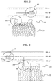
- Fig. 2 is an enlarged view of a coil rising part and a fastening part from a core unit not facing the lead-out part, of the axial gap rotary electric machine in the present embodiment. That is, Fig. 2 is an enlarged view of a core unit 34D as a core unit not facing the lead-out part in Fig. 1 , as viewed from the outer periphery, and the coil rising wire 35 raised by the coil rising part S1 is bent to the right side of the sheet, and fastened (T1) to the connecting wire 55-W with the T-type terminal 53.
- Fig. 1 is an enlarged view of a core unit 34D as a core unit not facing the lead-out part in Fig. 1 , as viewed from the outer periphery, and the coil rising wire 35 raised by the coil rising part S1 is bent to the right side of the sheet, and fastened (T1) to the connecting wire 55-W with the T-type terminal 53.
- Fig. 1 is an enlarged view of a coil rising part and
- FIG. 3 is an enlarged view of a coil rising part and a fastening part from the core unit facing the lead-out part, of the axial gap rotary electric machine in the present embodiment. That is, Fig. 3 is an enlarged view of the core unit 34A, which is a core unit facing the lead-out part in Fig. 1 , as viewed from the outer periphery, and the coil rising wire 35 raised by the coil rising part S0 is bent to the left side of the sheet, and is fastened (T0) to the connecting wire 55-W by the T-type terminal 53. That is, any fastening regions (T0, T1) are provided at positions facing the inner wall of the housing and not facing the lead-out part which is an opening of the housing.
- the coil rising wire 35 from the core units 34B to 34L not facing the lead-out part 45 is bent in the counterclockwise direction in the circumferential direction orthogonal to the rotation shaft and fastened to connecting wire 55.
- the coil rising wire 35 from the core unit 34A facing the lead-out part is bent in the clockwise direction and fastened to the connecting wire 55.
- the coil rising wire from the core unit not facing the lead-out part may be bent in the clockwise direction, and the coil rising wire from the core unit facing the lead-out part may be bent in the counterclockwise direction.
- the coil rising wire from the core unit can be configured to be fastened to the connecting wire except in the region facing the lead-out part. Therefore, the coil rising wire can be prevented from being pushed and moved in the outer peripheral direction by the sealing pressure of the resin flowing toward the lead-out part 45 at the time of resin molding, and it is possible to prevent the problem that the coil rising wire comes into contact with the housing 40 to cause a deterioration. That is, it is possible to provide an axial gap rotary electric machine capable of improving the reliability of the coil rising wire even if the stator is integrally molded.
- the present embodiment is configured so that the fastening region with the connecting wire of the coil rising wire from the core unit is disposed to avoid the region facing the lead-out part, in other words, the coil rising wire from the core unit is fastened to the connecting wire except in the region facing the lead-out part, it is possible to prevent the movement of the coil rising wire at the time of resin molding.
- the present invention is not limited to the above-described embodiments, and includes various modified examples.
- the above-described embodiment has been described by way of an example of an axial gap rotary electric machine of one stator and two rotors, it is apparent that the invention can be applied to one stator and one rotor or two stators and one rotor.
Landscapes
- Engineering & Computer Science (AREA)
- Power Engineering (AREA)
- Insulation, Fastening Of Motor, Generator Windings (AREA)
Applications Claiming Priority (1)
| Application Number | Priority Date | Filing Date | Title |
|---|---|---|---|
| PCT/JP2017/003294 WO2018142442A1 (fr) | 2017-01-31 | 2017-01-31 | Machine électrique tournante à entrefer axial |
Publications (2)
| Publication Number | Publication Date |
|---|---|
| EP3579386A1 true EP3579386A1 (fr) | 2019-12-11 |
| EP3579386A4 EP3579386A4 (fr) | 2020-10-21 |
Family
ID=63039451
Family Applications (1)
| Application Number | Title | Priority Date | Filing Date |
|---|---|---|---|
| EP17895183.6A Withdrawn EP3579386A4 (fr) | 2017-01-31 | 2017-01-31 | Machine électrique tournante à entrefer axial |
Country Status (5)
| Country | Link |
|---|---|
| US (1) | US11139714B2 (fr) |
| EP (1) | EP3579386A4 (fr) |
| JP (1) | JP6711927B2 (fr) |
| CN (1) | CN110089009B (fr) |
| WO (1) | WO2018142442A1 (fr) |
Cited By (1)
| Publication number | Priority date | Publication date | Assignee | Title |
|---|---|---|---|---|
| WO2023151753A1 (fr) * | 2022-02-14 | 2023-08-17 | Schaeffler Technologies AG & Co. KG | Machine à flux axial électrique |
Families Citing this family (2)
| Publication number | Priority date | Publication date | Assignee | Title |
|---|---|---|---|---|
| CN115943544A (zh) * | 2020-10-01 | 2023-04-07 | 株式会社村田制作所 | 无刷马达 |
| GB2619413B8 (en) * | 2023-05-18 | 2024-11-20 | High Tech Battery Inc | Axial flux machine and stator for axial flux machine |
Family Cites Families (18)
| Publication number | Priority date | Publication date | Assignee | Title |
|---|---|---|---|---|
| US6856055B2 (en) * | 2002-07-11 | 2005-02-15 | Emerson Electric Co. | Interconnecting ring and wire guide |
| JP4305649B2 (ja) * | 2003-02-26 | 2009-07-29 | 株式会社富士通ゼネラル | アキシャルギャップ型電動機 |
| CN1767319B (zh) * | 2004-10-29 | 2010-09-29 | 株式会社日立制作所 | 旋转电机及其制造方法 |
| JP2006166598A (ja) * | 2004-12-07 | 2006-06-22 | Asmo Co Ltd | ブラシレスモータおよびブラシレスファンモータ装置並びにブラシレスモータの製造方法 |
| CN2862282Y (zh) * | 2005-12-13 | 2007-01-24 | 中电电气集团有限公司 | 非包封干式变压器10kV级多绕组引线结构 |
| JP4868147B2 (ja) * | 2006-11-08 | 2012-02-01 | 株式会社富士通ゼネラル | アキシャルエアギャップ型電動機 |
| JP4737054B2 (ja) * | 2006-11-30 | 2011-07-27 | トヨタ自動車株式会社 | 絶縁部材およびステータ |
| JP4465395B2 (ja) * | 2008-04-15 | 2010-05-19 | 本田技研工業株式会社 | 回転電機の集配電リング |
| US8154163B2 (en) * | 2008-04-15 | 2012-04-10 | Honda Motor Co., Ltd. | Electric power collection/distribution ring of rotary electric machine |
| JP5740931B2 (ja) * | 2010-03-03 | 2015-07-01 | 日本電産株式会社 | 分割ステータ、及びモータ |
| DE112012004866B4 (de) * | 2011-11-22 | 2024-03-14 | Honda Motor Co., Ltd. | Elektrische Umlaufmaschine |
| CN202488320U (zh) * | 2011-12-26 | 2012-10-10 | 深圳市祺金泰电机科技有限公司 | 一种无刷直流电机装置 |
| JP5924082B2 (ja) * | 2012-03-31 | 2016-05-25 | 日本電産株式会社 | モールドモータステータ部とそれを用いるモールドモータ |
| JP6221034B2 (ja) * | 2013-03-29 | 2017-11-01 | 日本電産株式会社 | モータおよびモータの製造方法 |
| WO2015059776A1 (fr) * | 2013-10-22 | 2015-04-30 | 三菱電機株式会社 | Stator moule, moteur electrique moule et climatiseur |
| JP5738385B2 (ja) * | 2013-11-18 | 2015-06-24 | 三菱電機株式会社 | 固定子およびその固定子を備えた回転電機 |
| US11165312B2 (en) | 2014-04-14 | 2021-11-02 | Hitachi Industrial Equipment Systems Co., Ltd. | Axial-gap dynamo-electric machine |
| JP2017005855A (ja) * | 2015-06-10 | 2017-01-05 | 日立アプライアンス株式会社 | ポンプ装置の駆動用モータ |
-
2017
- 2017-01-31 CN CN201780078965.4A patent/CN110089009B/zh active Active
- 2017-01-31 WO PCT/JP2017/003294 patent/WO2018142442A1/fr not_active Ceased
- 2017-01-31 JP JP2018565088A patent/JP6711927B2/ja active Active
- 2017-01-31 US US16/475,736 patent/US11139714B2/en active Active
- 2017-01-31 EP EP17895183.6A patent/EP3579386A4/fr not_active Withdrawn
Cited By (1)
| Publication number | Priority date | Publication date | Assignee | Title |
|---|---|---|---|---|
| WO2023151753A1 (fr) * | 2022-02-14 | 2023-08-17 | Schaeffler Technologies AG & Co. KG | Machine à flux axial électrique |
Also Published As
| Publication number | Publication date |
|---|---|
| WO2018142442A1 (fr) | 2018-08-09 |
| EP3579386A4 (fr) | 2020-10-21 |
| US20210135530A1 (en) | 2021-05-06 |
| US11139714B2 (en) | 2021-10-05 |
| JP6711927B2 (ja) | 2020-06-17 |
| JPWO2018142442A1 (ja) | 2019-11-07 |
| CN110089009B (zh) | 2021-03-23 |
| CN110089009A (zh) | 2019-08-02 |
Similar Documents
| Publication | Publication Date | Title |
|---|---|---|
| CN102801242B (zh) | 旋转电机 | |
| EP3176912B1 (fr) | Stator et machine tournante | |
| US9685844B2 (en) | Motor and method of manufacturing motor | |
| TWI646758B (zh) | 軸向間隙型旋轉電機 | |
| US20190103781A1 (en) | Motor | |
| US11139714B2 (en) | Axial gap rotary electric machine | |
| KR20220069644A (ko) | 모터 | |
| TWI673936B (zh) | 軸向間隙型旋轉電機 | |
| US8823240B2 (en) | Stator and rotating electrical machine | |
| JP5233630B2 (ja) | ステータ、回転電機、ステータの製造方法および回転電機の製造方法 | |
| JP7691374B2 (ja) | バスバーユニット | |
| WO2011114758A1 (fr) | Stator et machine dynamo-électrique | |
| JP7109550B2 (ja) | 回転電機 | |
| WO2021079777A1 (fr) | Isolateur, moteur, ventilateur et climatiseur | |
| JP2014192997A (ja) | 電動モータ | |
| KR101939191B1 (ko) | 트랙션 모터 | |
| WO2019064747A1 (fr) | Rotor et moteur pourvu de ce dernier | |
| JP2018088790A (ja) | 回転電機 |
Legal Events
| Date | Code | Title | Description |
|---|---|---|---|
| STAA | Information on the status of an ep patent application or granted ep patent |
Free format text: STATUS: THE INTERNATIONAL PUBLICATION HAS BEEN MADE |
|
| PUAI | Public reference made under article 153(3) epc to a published international application that has entered the european phase |
Free format text: ORIGINAL CODE: 0009012 |
|
| STAA | Information on the status of an ep patent application or granted ep patent |
Free format text: STATUS: REQUEST FOR EXAMINATION WAS MADE |
|
| 17P | Request for examination filed |
Effective date: 20190902 |
|
| AK | Designated contracting states |
Kind code of ref document: A1 Designated state(s): AL AT BE BG CH CY CZ DE DK EE ES FI FR GB GR HR HU IE IS IT LI LT LU LV MC MK MT NL NO PL PT RO RS SE SI SK SM TR |
|
| AX | Request for extension of the european patent |
Extension state: BA ME |
|
| DAV | Request for validation of the european patent (deleted) | ||
| DAX | Request for extension of the european patent (deleted) | ||
| A4 | Supplementary search report drawn up and despatched |
Effective date: 20200918 |
|
| RIC1 | Information provided on ipc code assigned before grant |
Ipc: H02K 3/52 20060101ALI20200914BHEP Ipc: H02K 5/08 20060101ALI20200914BHEP Ipc: H02K 21/02 20060101ALI20200914BHEP Ipc: H02K 3/46 20060101AFI20200914BHEP |
|
| RIN1 | Information on inventor provided before grant (corrected) |
Inventor name: YONEOKA, YASUEI Inventor name: TAKAHASHI, SHUUICHI Inventor name: SUZUKI, TOSHIFUMI Inventor name: SAKAI, TORU Inventor name: YAMAZAKI, KATSUYUKI Inventor name: TAKAHASHI, DAISAKU Inventor name: KURAI, DAISUKE |
|
| STAA | Information on the status of an ep patent application or granted ep patent |
Free format text: STATUS: EXAMINATION IS IN PROGRESS |
|
| 17Q | First examination report despatched |
Effective date: 20220316 |
|
| GRAP | Despatch of communication of intention to grant a patent |
Free format text: ORIGINAL CODE: EPIDOSNIGR1 |
|
| STAA | Information on the status of an ep patent application or granted ep patent |
Free format text: STATUS: GRANT OF PATENT IS INTENDED |
|
| INTG | Intention to grant announced |
Effective date: 20240102 |
|
| STAA | Information on the status of an ep patent application or granted ep patent |
Free format text: STATUS: THE APPLICATION IS DEEMED TO BE WITHDRAWN |
|
| 18D | Application deemed to be withdrawn |
Effective date: 20240503 |