EP3579401B1 - Groupe électrogène à onduleur et son procédé de commande - Google Patents
Groupe électrogène à onduleur et son procédé de commande Download PDFInfo
- Publication number
- EP3579401B1 EP3579401B1 EP17895011.9A EP17895011A EP3579401B1 EP 3579401 B1 EP3579401 B1 EP 3579401B1 EP 17895011 A EP17895011 A EP 17895011A EP 3579401 B1 EP3579401 B1 EP 3579401B1
- Authority
- EP
- European Patent Office
- Prior art keywords
- power
- value
- rotation speed
- inverter
- target
- Prior art date
- Legal status (The legal status is an assumption and is not a legal conclusion. Google has not performed a legal analysis and makes no representation as to the accuracy of the status listed.)
- Active
Links
Images


Classifications
-
- H—ELECTRICITY
- H02—GENERATION; CONVERSION OR DISTRIBUTION OF ELECTRIC POWER
- H02M—APPARATUS FOR CONVERSION BETWEEN AC AND AC, BETWEEN AC AND DC, OR BETWEEN DC AND DC, AND FOR USE WITH MAINS OR SIMILAR POWER SUPPLY SYSTEMS; CONVERSION OF DC OR AC INPUT POWER INTO SURGE OUTPUT POWER; CONTROL OR REGULATION THEREOF
- H02M7/00—Conversion of AC power input into DC power output; Conversion of DC power input into AC power output
- H02M7/42—Conversion of DC power input into AC power output without possibility of reversal
- H02M7/44—Conversion of DC power input into AC power output without possibility of reversal by static converters
- H02M7/48—Conversion of DC power input into AC power output without possibility of reversal by static converters using discharge tubes with control electrode or semiconductor devices with control electrode
- H02M7/53—Conversion of DC power input into AC power output without possibility of reversal by static converters using discharge tubes with control electrode or semiconductor devices with control electrode using devices of a triode or transistor type requiring continuous application of a control signal
- H02M7/537—Conversion of DC power input into AC power output without possibility of reversal by static converters using discharge tubes with control electrode or semiconductor devices with control electrode using devices of a triode or transistor type requiring continuous application of a control signal using semiconductor devices only, e.g. single switched pulse inverters
-
- H—ELECTRICITY
- H02—GENERATION; CONVERSION OR DISTRIBUTION OF ELECTRIC POWER
- H02P—CONTROL OR REGULATION OF ELECTRIC MOTORS, ELECTRIC GENERATORS OR DYNAMO-ELECTRIC CONVERTERS; CONTROLLING TRANSFORMERS, REACTORS OR CHOKE COILS
- H02P9/00—Arrangements for controlling electric generators for the purpose of obtaining a desired output
- H02P9/04—Control effected upon non-electric prime mover and dependent upon electric output value of the generator
-
- H—ELECTRICITY
- H02—GENERATION; CONVERSION OR DISTRIBUTION OF ELECTRIC POWER
- H02P—CONTROL OR REGULATION OF ELECTRIC MOTORS, ELECTRIC GENERATORS OR DYNAMO-ELECTRIC CONVERTERS; CONTROLLING TRANSFORMERS, REACTORS OR CHOKE COILS
- H02P25/00—Arrangements or methods for the control of AC motors characterised by the kind of AC motor or by structural details
- H02P25/16—Arrangements or methods for the control of AC motors characterised by the kind of AC motor or by structural details characterised by the circuit arrangement or by the kind of wiring
- H02P25/22—Multiple windings; Windings for more than three phases
-
- H—ELECTRICITY
- H02—GENERATION; CONVERSION OR DISTRIBUTION OF ELECTRIC POWER
- H02P—CONTROL OR REGULATION OF ELECTRIC MOTORS, ELECTRIC GENERATORS OR DYNAMO-ELECTRIC CONVERTERS; CONTROLLING TRANSFORMERS, REACTORS OR CHOKE COILS
- H02P27/00—Arrangements or methods for the control of AC motors characterised by the kind of supply voltage
- H02P27/04—Arrangements or methods for the control of AC motors characterised by the kind of supply voltage using variable-frequency supply voltage, e.g. inverter or converter supply voltage
- H02P27/06—Arrangements or methods for the control of AC motors characterised by the kind of supply voltage using variable-frequency supply voltage, e.g. inverter or converter supply voltage using DC to AC converters or inverters
- H02P27/08—Arrangements or methods for the control of AC motors characterised by the kind of supply voltage using variable-frequency supply voltage, e.g. inverter or converter supply voltage using DC to AC converters or inverters with pulse width modulation
-
- H—ELECTRICITY
- H02—GENERATION; CONVERSION OR DISTRIBUTION OF ELECTRIC POWER
- H02P—CONTROL OR REGULATION OF ELECTRIC MOTORS, ELECTRIC GENERATORS OR DYNAMO-ELECTRIC CONVERTERS; CONTROLLING TRANSFORMERS, REACTORS OR CHOKE COILS
- H02P9/00—Arrangements for controlling electric generators for the purpose of obtaining a desired output
- H02P9/10—Control effected upon generator excitation circuit to reduce harmful effects of overloads or transients, e.g. sudden application of load, sudden removal of load, sudden change of load
Definitions
- the present invention relates to an inverter power generator and a method for controlling the inverter power generator.
- inverter power generators that convert alternating current (AC) power from a power generating unit driven by an engine into direct current (DC) power via a converter and convert the DC power from the converter into AC power via an inverter to output to a load have been known.
- AC alternating current
- DC direct current
- the target rotation speed of the engine is determined in accordance with the output power from the inverter.
- the target rotation speed of the engine may be determined in accordance with the output current of the inverter in some cases.
- Patent Literature 1 describes that the target rotation speed of the engine is determined in accordance with the effective power consumed by a load.
- JP H05 18285 A discloses an inverter type engine generator, in which the output current of a generator is detected by a current detector and the output voltage thereof by a voltage detector. Based on a load detecting current detected by the current detector, a reference target rotation speed of an engine is calculated. Only when a detecting voltage detected by the voltage detector is lower than a rated voltage, a correction rotation speed is calculated. The correction rotation speed is added to the reference target rotation speed to calculate a corrected target rotation speed.
- JP 2010 035262 A discloses an inverter power generator in which an alternating-current voltage and current outputted from an inverter are detected. A power factor is computed based on the detected voltage and current. An estimated load power is computed based on at least the detected current and the computed power factor. A target number of engine revolutions is determined based thereon and the operation of an actuator is controlled so that this target number of revolutions is obtained.
- Patent Literature 1 Japanese Patent Laid-open Publication No. 2012-244699
- the above-described conventional inverter power generator may suffer from a drop in the output voltage of the inverter when a load varies (mainly, in applying a load). In this case, as the drop in the output voltage of the inverter leads to a drop in the target rotation speed of the engine, the engine cannot be sufficiently accelerated, and the responsiveness in controlling the engine rotation speed may not possibly be sufficient.
- the present invention has been conceived in view of the above-described problem, and aims to provide an inverter power generator capable of improving responsiveness in controlling the rotation speed of an engine when a load varies, and a method for controlling the inverter power generator.
- an inverter power generator includes: an engine; an actuator for adjusting the position of a throttle valve of the engine; a power generating unit for generating AC power from a driving force of the engine; a converter for converting the AC power outputted from the power generating unit into DC power; an inverter for converting the DC power outputted from the converter into AC power; a current detection unit for detecting the current of the AC power outputted from the inverter; a voltage detection unit for detecting the voltage of the AC power outputted from the inverter; a target rotation speed determination unit for determining a target rotation speed of the engine, based on the detected current value detected by the current detection unit and a correction value in accordance with the difference between a target voltage value of the AC power outputted from the inverter and the detected voltage value detected by the voltage detection unit; and an actuator control unit for controlling the actuator, based on the target rotation speed determined.
- the target rotation speed determination unit is configured to determine the target rotation speed, based on a power value and the correction value, the power value being calculated, based on the detected current value and the detected voltage value.
- the target rotation speed determination unit is configured to determine the target rotation speed, based on a corrected power value calculated based on the power value and the correction value.
- the corrected power value is a value obtained by dividing the power value by a ratio of the detected voltage value to the target voltage value.
- a method for controlling an inverter power generator is a method for controlling an inverter power generator including an engine; an actuator for adjusting the position of a throttle valve of the engine; a power generating unit for generating AC power from a driving force of the engine; a converter for converting the AC power outputted from the power generating unit into DC power; an inverter for converting the DC power outputted from the converter into AC power; a current detection unit for detecting the current of the AC power outputted from the inverter; and a voltage detection unit for detecting the voltage of the AC power outputted from the inverter, the method including: determining a target rotation speed of the engine, based on the detected current value detected by the current detection unit and a correction value in accordance with the difference between a target voltage value of the AC power outputted from the inverter and the detected voltage value detected by the voltage detection unit; and controlling the actuator, based on the target rotation speed determined.
- the target rotation speed is determined based on a power value and the correction value, the power value being calculated, based on the detected current value and the detected voltage value.
- the target rotation speed is determined based on a corrected power value calculated based on the power value and the correction value.
- the corrected power value is a value obtained by dividing the power value by a ratio of the detected voltage value to the target voltage value.
- the target rotation speed of an engine is determined using a correction value in accordance with the difference between a target voltage value and a detected voltage value. This makes it possible to improve responsiveness in controlling the engine rotation speed even when the output voltage of an inverter drops due to variations in the load.
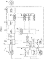
- FIG. 1 is a block diagram illustrating an example of an inverter power generator according to an embodiment.
- the inverter power generator 1 includes an engine 2.
- the engine 2 is an internal combustion engine that ignites fuel, such as gasoline, with sparks.
- the engine 2 has a throttle motor 27 for adjusting the position of a throttle valve 25 provided to an inlet pipe.
- the throttle motor 27 is one example of an actuator and includes, for example, a stepping motor.
- the engine 2 is connected to power generating units 21, 23.
- Each of the power generating units 21, 23 has a rotor having permanent magnets that rotates together with the output shaft of the engine 2, and a stator including a coil disposed so as to intersect with the magnetic flux from the permanent magnet.
- the main power generating unit 21 has coils for three phases (U, V, and W-phases).
- the main power generating unit 21 generates three-phase AC power from a driving force of the engine 2 and outputs to a control device 10.
- the sub-power generating unit 23 has single-phase coils.
- the sub-power generating unit 23 generates single-phase AC power from the driving force of the engine 2 and outputs to the control device 10.
- the single-phase AC power inputted from the sub-power generating unit 23 to the control device 10 is converted into DC power via a control power supply 7 to be supplied to the respective units in the control device 10.
- the control device 10 includes an SCR/DI bridge 31, a smoothing capacitor 33, an FET bridge 35, a choke coil 37, and a noise filter 39 connected in this sequence on a path for feeding the power from the main power generating unit 21 to an AC output unit 8.
- the SCR/DI bridge 31 is an example of a converter
- the FET bridge 35 is an example of an inverter.
- the SCR/DI bridge 31 converts the three-phase AC power outputted from the main power generating unit 21 into DC power.
- the SCR/DI bridge 31 is a three-phase bridge converter including three thyristors (SCR) and three diodes (DI), and converts three-phase AC power into DC power through full-wave rectification with the continuity of the thyristors being controlled.
- the smoothing capacitor 33 smooths the DC power outputted from the SCR/DI bridge 31.
- the FET bridge 35 converts the DC power outputted from the SCR/DI bridge 31 and smoothed by the smoothing capacitor 33, into AC power.
- the FET bridge 35 is a single-phase bridge inverter including four field effect transistors (FET), and converts DC power into AC power having a predetermined frequency (for example, 50 or 60 Hz) through control of the continuity of the FETs.
- the AC power outputted from the FET bridge 35 passes through the choke coil 37 for removing harmonic waves and a noise filter 39 for removing noises to be outputted from the AC output unit 8 to the outside.
- a plurality of inverter power generators 1A, 1B can be connected in parallel for use.
- the AC powers outputted from the respective inverter power generators 1A, 1B are combined by a combined AC output unit 80 and outputted to the outside.
- the control device 10 has a Central Processing Unit (CPU) 3.
- CPU Central Processing Unit
- the CPU 3 controls the throttle motor 27 via a motor driver 41, the SCR/DI bridge 31 via an SCR driver 43, and the FET bridge 35 via an FET driver 45.
- the CPU 3 applies pulse width modulation (PWM) control to the FET bridge 35.
- PWM pulse width modulation
- An NE detector 51 supplies a detected signal to the CPU 3 which indicates the rotation speed of the engine.
- the NE detector 51 generates a pulse signal from an output from the power generating unit 21. Counting the pulse signals, the CPU 3 calculates the engine rotation speed.
- a current detector 61 supplies a detected signal to the CPU 3, the detected signal indicating the output current of the AC power outputted from the FET bridge 35 and measured by a current sensor 55.
- the current sensor 55 is disposed, for example, between the choke coil 37 and the noise filter 39.
- An overcurrent detector 63 supplies a detected signal indicating generation of an overcurrent to the CPU 3 when the output current outputted from the FET bridge 35 exceeds a threshold.
- a voltage detector 65 supplies a detected signal to the CPU 3 which indicates the output voltage of the AC power outputted from the FET bridge 35.
- the voltage detector 65 is connected, for example, between the choke coil 37 and the noise filter 39.
- the CPU 3 executes a program stored in a memory, not illustrated, to function as a target rotation speed determination unit for determining a target engine rotation speed, and an actuator controller for controlling the throttle motor 27, based on the determined target engine rotation speed.
- a target rotation speed determination unit for determining a target engine rotation speed
- an actuator controller for controlling the throttle motor 27, based on the determined target engine rotation speed.
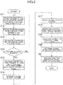
- FIG. 3 is a flowchart of an example of a method for controlling an inverter power generator according to an embodiment. Following a program stored in the memory, not illustrated, the CPU 3 repetitively executes the engine rotation speed control illustrated in FIG. 3 in a predetermined cycle.
- Pac_w Pac_total / total of PWM carrier cycle points for one AC cycle
- the effective power can be calculated by multiplying the AC power outputted from the FET bridge 35 by a power factor cos ⁇ that is based on the phase difference ⁇ between the output voltage and output current outputted from the FET bridge 35.
- the CPU 3 calculates a correction factor. Specifically, the CPU 3 determines a target output voltage for the AC power to be outputted from the FET bridge 35 (S16), detects the actual output voltage of the AC power outputted from the FET bridge 35, via the voltage detector 65 (S17), and divides the target output voltage by the actual output voltage to calculate a correction factor k (S18) .
- the actual output voltage is an effective value for one AC cycle. Specifically, the actual output voltage is a voltage value obtained by integrating the detected instantaneous output voltages Vac for one AC cycle and averaging the integrated value.
- the correction factor k is a value in accordance with the difference between the target output voltage and the actual output voltage, and, for example, increases when the difference between the target output voltage and the actual output voltage increases.
- the correction factor k is not limited to a quotient obtained by dividing the target output voltage by the actual output voltage, but may be the difference obtained by subtracting the actual output voltage from the target output voltage.
- the target output value is not a fixed value, though close to a rating voltage (for example, 100V), but varies in accordance with the effective power, as to be described later.
- the CPU 3 calculates a corrected effective power, based on the effective power calculated at S15 mentioned above and the correction factor calculated at 18 mentioned above. Specifically, the CPU 3 multiplies the effective power Pac_w by the correction factor k to calculate a corrected effective power Pac_hw. For example, the corrected effective power Pac_hw increases when the difference between the target output voltage and the actual output voltage increases.
- the corrected effective power Pac_hw which is a value obtained by multiplying the effective power Pac_w by the correction factor k, can be rephrased as a value obtained by dividing the effective power Pac_w by the ratio of the actual output voltage to the target output voltage (that is, the reciprocal of the correction factor k) (refer to Expression 1 below).
- the CPU 3 determines the target engine rotation speed, based on the corrected effective power calculated at S19 mentioned above. Specifically, the CPU 3 reads a target engine rotation speed corresponding to the corrected effective power Pac_hw from a look-up table stored in a memory, not illustrated.
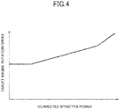
- FIG. 4 illustrates an example of a relationship between the corrected effective power and the target engine rotation speed.
- the target engine rotation speed is set such that a higher corrected effective power leads to a higher target engine rotation speed. That is, the target engine rotation speed, which is based on the corrected effective power, is higher, for example, when the difference between the target output voltage and the actual output voltage is larger.
- the CPU 3 controls the throttle motor 27, based on the target engine rotation speed determined at S20 mentioned above. Specifically, the CPU 3 applies feedback control to the throttle motor 27 such that the difference between the determined target engine rotation speed and the detected actual engine rotation speed is reduced.
- the target engine rotation speed is determined based on the corrected effective power, it is possible to improve the responsiveness in controlling the engine rotation speed. That is, the corrected effective power is corrected so as to increase when the difference between the target output voltage and the actual output voltage increases. Accordingly, the target engine rotation speed is determined so as to increase when the difference between the target output voltage and the actual output voltage increases. This makes it possible to promptly increase the engine rotation speed.
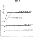
- FIG. 5 illustrates an example of change as time passes in the output voltage, the effective power, and the engine rotation speed.
- the solid lines in the drawing indicate an embodiment of change as time passes when the target engine rotation speed is determined based on the corrected effective power.
- the broken lines in the drawing indicate as a reference example of change time passes when the target engine rotation speed is determined based on the effective power that is not corrected.
- the engine 2 Before application of a load to the AC output unit 8, the engine 2 remains in an idle state, and the output voltage of the inverter power generator 1 is kept at the target output voltage.
- the output voltage of the inverter power generator 1 instantaneously drops from the target output voltage. Hence, the effective power does not rise instantly to a sufficient level.
- a relatively low target engine rotation speed is set in the reference example. Thus, it takes time for the engine rotation speed to increase.
- the target engine rotation speed is determined, based on the corrected effective power, which has been corrected so as to increase when the difference between the target output voltage and the actual output voltage increases. Consequently, a relatively high target engine rotation speed is set. This makes it possible for the engine rotation speed to increase promptly.
- FIG. 5 illustrates a time of application of a load as an example, this is not exclusive, and the responsiveness in controlling the engine rotation speed can be similarly improved at any other time when the load varies.
- This embodiment is not limited to an aspect in which the target engine rotation speed is determined based on the effective power, but is applicable to an aspect in which the target engine rotation speed is determined based on an output current and also to an aspect in which the target engine rotation speed is determined based on an apparent power. That is, the output current or the apparent power may be corrected so as to increase when the difference between the target output voltage and the actual output voltage increases before determination of the target engine rotation speed based on the corrected output current or apparent power.
- This embodiment produces a remarkable effect when an inductive load is connected in an aspect in which the target engine rotation speed is determined based on the effective power. That is, in the case that an inductive load is connected, the effective power (a power consumed in a load) is small, and accordingly a relatively low target engine rotation speed is set in an aspect with the effective power being used. This likely results in lower responsiveness in controlling the engine rotation speed, compared with an aspect in which an output current or an apparent power is used.
- the effective power is corrected so as to increase when the difference between the target output voltage and the actual output voltage increases, and the target engine rotation speed is determined based on the corrected effective power. This makes it possible to improve the responsiveness in controlling the engine rotation speed even in an aspect in which the effective power is used.
- a method for correcting the effective power, using a correction value is not particularly limited, provided that a higher target engine rotation speed is finally resulted when the difference between the target output voltage and the actual output voltage increases.
- the target engine rotation speed may be determined based on the effective power, and then corrected using a correction value.
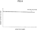
- FIG. 6 illustrates an example of a relationship between the effective power and the target output voltage.
- the target output voltage takes a value close to the rating voltage (for example, 100V), and varies in accordance with the effective power. Specifically, the target output voltage linearly varies so as to become gradually lower as the effective power becomes higher.
- Such variation is intended to reduce a charging current that flows from one to the other of the inverter power generators 1A, 1B connected in parallel as illustrated in FIG. 2 . That is, as illustrated in FIG. 7A and FIG. 7B , the characteristics of the inverter power generators 1A, 1B may differ from each other. Thus, the effective powers of the respective inverter power generators 1A, 1B connected in parallel to output the same output voltage may differ from each other. In this case, a charging current in accordance with the difference in the effective power flows from one to the other of the inverter power generators 1A, 1B.
- the charging current is higher when the inclination of a straight line indicating the relationship between the effective power and the output voltage is smaller, and lower when the inclination is larger.
- the straight line indicating the relationship between the effective power and the target output voltage is provided with an inclination as is illustrated in FIG. 6 .
- the effective power is calculated based on the detected output voltage and the detected output current, and the correction factor is calculated using the target output voltage, which varies in accordance with the effective power. This makes it possible to set an appropriate target engine rotation speed.
- calculation of a power or a correction factor based on an assumption that an output voltage is a fixed value when the output voltage actually varies may possibly hinder setting of an appropriate target engine rotation speed.
- the target engine rotation speed may be set below an appropriate level, and a sufficient power may not possibly be obtained.
- the correction factor may not be large enough, and it thus may possibly take time for the engine rotation speed to increase.
- the target engine rotation speed may be set in excess of an appropriate level, which may possibly adversely affect the fuel consumption and noise.
Landscapes
- Engineering & Computer Science (AREA)
- Power Engineering (AREA)
- Control Of Eletrric Generators (AREA)
Claims (7)
- Groupe électrogène à onduleur (1, 1A, 1B), comprenant:un moteur (2);un actionneur (27) destiné à ajuster une position d'une soupape d'étranglement (25) du moteur (2);une unité de génération d'énergie (21) destinée à générer du courant alternatif à partir d'une force d'entraînement du moteur (2);un convertisseur (31) destiné à convertir le courant alternatif sorti par l'unité de génération d'énergie (21) en courant continu;un onduleur (35) destiné à convertir le courant continu sorti par le convertisseur (31) en courant alternatif;une unité de détection de courant (61) destinée à détecter un courant du courant alternatif sorti par l'onduleur (35);une unité de détection de tension (65) destinée à détecter une tension du courant alternatif sorti par l'onduleur (35);une unité de détermination de vitesse de rotation cible (3) destinée à déterminer une vitesse de rotation cible du moteur (2) sur base d'une valeur de courant détectée par l'unité de détection de courant (61) et d'une valeur de correction (k) selon une différence entre une valeur de tension cible du courant alternatif sorti par l'onduleur (35) et une valeur de tension détectée par l'unité de détection de tension (65); etune unité de commande d'actionneur (3) destinée à commander l'actionneur (27) sur base de la vitesse de rotation cible déterminée,caractérisé par le fait que l'unité de détermination de vitesse de rotation cible (3) est configurée pour déterminer la vitesse de rotation cible sur base d'une valeur de puissance et de la valeur de correction (k), la valeur de puissance étant calculée sur base de la valeur de courant détectée et de la valeur de tension détectée,dans lequel l'unité de détermination de vitesse de rotation cible (3) est configurée pour déterminer la vitesse de rotation cible sur base d'une valeur de puissance corrigée calculée sur base de la valeur de puissance et de la valeur de correction (k), etdans lequel la valeur de puissance corrigée est une valeur obtenue en divisant la valeur de puissance par un rapport entre la valeur de tension détectée et la valeur de tension cible.
- Groupe électrogène à onduleur (1, 1A, 1B) selon la revendication 1, dans lequel la valeur de puissance est une valeur de puissance d'une puissance effective.
- Groupe électrogène à onduleur (1, 1A, 1B) selon la revendication 1, dans lequel la vitesse de rotation cible augmente lorsqu'une différence entre la valeur de tension cible et la valeur de tension détectée augmente.
- Groupe électrogène à onduleur (1, 1A, 1B) selon la revendication 1, dans lequel la valeur de puissance corrigée augmente lorsqu'une différence entre la valeur de tension cible et la valeur de tension détectée augmente.
- Groupe électrogène à onduleur (1, 1A, 1B) selon la revendication 1, dans lequel l'unité de détermination de la vitesse de rotation cible (3) est configurée pour lire la vitesse de rotation cible correspondant à la valeur de puissance corrigée dans un tableau de consultation.
- Groupe électrogène à onduleur (1, 1A, 1B) selon la revendication 2, dans lequel la valeur de tension cible varie de manière à devenir progressivement inférieure au fur et à mesure que la puissance effective devient supérieure.
- Procédé de commande d'un groupe électrogène à onduleur (1, 1A, 1B) comportant un moteur (2); un actionneur (27) destiné à ajuster une position d'une soupape d'étranglement (25) du moteur (2); une unité de génération d'énergie (21) destinée à générer du courant alternatif à partir d'une force d'entraînement du moteur (2); un convertisseur (31) destiné à convertir le courant alternatif sorti par l'unité de génération de courant (21) en courant continu; un onduleur (35) destiné à convertir le courant continu sorti par le convertisseur (31) en courant alternatif; une unité de détection de courant (61) destinée à détecter un courant du courant alternatif sorti par l'onduleur (35); et une unité de détection de tension (65) destinée à détecter une tension du courant alternatif sorti par l'onduleur (35), le procédé comprenant le fait de:déterminer (S20) une vitesse de rotation cible du moteur (2) sur base d'une valeur de courant détectée par l'unité de détection de courant (61) et d'une valeur de correction (k) selon une différence entre une valeur de tension cible du courant alternatif sorti par l'onduleur (35) et une valeur de tension détectée par l'unité de détection de tension (65); etcommander (S21) l'actionneur (27) sur base de la vitesse de rotation cible déterminée,caractérisé par le fait que la vitesse de rotation cible est déterminée sur base d'une valeur de puissance et de la valeur de correction (k), la valeur de puissance étant calculée sur base de la valeur de courant détectée et de la valeur de tension détectée,dans lequel la vitesse de rotation cible est déterminée sur base d'une valeur de puissance corrigée calculée sur base de la valeur de puissance et de la valeur de correction (k), etdans lequel la valeur de puissance corrigée est une valeur obtenue en divisant la valeur de puissance par un rapport entre la valeur de tension détectée et la valeur de tension cible.
Applications Claiming Priority (2)
| Application Number | Priority Date | Filing Date | Title |
|---|---|---|---|
| JP2017019304A JP6279777B1 (ja) | 2017-02-06 | 2017-02-06 | インバータ発電機及びその制御方法 |
| PCT/JP2017/036983 WO2018142676A1 (fr) | 2017-02-06 | 2017-10-12 | Groupe électrogène à onduleur et son procédé de commande |
Publications (3)
| Publication Number | Publication Date |
|---|---|
| EP3579401A1 EP3579401A1 (fr) | 2019-12-11 |
| EP3579401A4 EP3579401A4 (fr) | 2020-11-04 |
| EP3579401B1 true EP3579401B1 (fr) | 2022-05-04 |
Family
ID=61195686
Family Applications (1)
| Application Number | Title | Priority Date | Filing Date |
|---|---|---|---|
| EP17895011.9A Active EP3579401B1 (fr) | 2017-02-06 | 2017-10-12 | Groupe électrogène à onduleur et son procédé de commande |
Country Status (7)
| Country | Link |
|---|---|
| US (1) | US11011998B2 (fr) |
| EP (1) | EP3579401B1 (fr) |
| JP (1) | JP6279777B1 (fr) |
| CN (1) | CN110249521B (fr) |
| AU (1) | AU2017397532B2 (fr) |
| CA (1) | CA3052550A1 (fr) |
| WO (1) | WO2018142676A1 (fr) |
Families Citing this family (2)
| Publication number | Priority date | Publication date | Assignee | Title |
|---|---|---|---|---|
| WO2022180703A1 (fr) * | 2021-02-24 | 2022-09-01 | 本田技研工業株式会社 | Générateur, dispositif de commande et procédé de commande |
| KR102767752B1 (ko) * | 2024-06-05 | 2025-02-14 | 주식회사 대흥기전 | 순시전력 검출을 이용하는 비상발전기시스템의 연료공급량제어장치 |
Family Cites Families (15)
| Publication number | Priority date | Publication date | Assignee | Title |
|---|---|---|---|---|
| JPH0518285A (ja) * | 1991-07-05 | 1993-01-26 | Kubota Corp | インバータ式エンジン発電機 |
| JP2758782B2 (ja) * | 1992-05-22 | 1998-05-28 | 三菱電機株式会社 | 電源装置 |
| US6281664B1 (en) * | 1999-01-13 | 2001-08-28 | Honda Giken Kogyo Kabushiki Kaisha | Generator and generator apparatus |
| JP2004040876A (ja) * | 2002-07-01 | 2004-02-05 | Kokusan Denki Co Ltd | 電源装置搭載内燃機関駆動車両の制御装置 |
| JP2005057900A (ja) * | 2003-08-05 | 2005-03-03 | Kokusan Denki Co Ltd | エンジン駆動インバータ発電装置 |
| JP2005137149A (ja) * | 2003-10-31 | 2005-05-26 | Mitsubishi Heavy Ind Ltd | パワーコンディショナ及び発電システム |
| JPWO2008026269A1 (ja) * | 2006-08-31 | 2010-01-14 | 三菱電機株式会社 | 電力変換装置 |
| JP2009071898A (ja) * | 2007-09-10 | 2009-04-02 | Toyota Motor Corp | 蓄電機構の充電制御システムおよびその制御方法 |
| JP2010011687A (ja) * | 2008-06-30 | 2010-01-14 | Hitachi Ltd | 電動駆動制御装置、電動車両および過電圧防止方法 |
| JP2010031660A (ja) * | 2008-07-25 | 2010-02-12 | Honda Motor Co Ltd | インバータ発電機 |
| JP5130142B2 (ja) * | 2008-07-25 | 2013-01-30 | 本田技研工業株式会社 | インバータ発電機 |
| JP5130143B2 (ja) | 2008-07-25 | 2013-01-30 | 本田技研工業株式会社 | インバータ発電機 |
| JP5497316B2 (ja) * | 2009-03-27 | 2014-05-21 | ヤマハモーターパワープロダクツ株式会社 | インバータ式発電機 |
| JP5745931B2 (ja) * | 2011-05-17 | 2015-07-08 | 本田技研工業株式会社 | インバータ発電機の制御装置 |
| JP5911513B2 (ja) * | 2011-12-14 | 2016-04-27 | 三菱電機株式会社 | ハイブリッド車両の発電機制御装置 |
-
2017
- 2017-02-06 JP JP2017019304A patent/JP6279777B1/ja active Active
- 2017-10-12 WO PCT/JP2017/036983 patent/WO2018142676A1/fr not_active Ceased
- 2017-10-12 AU AU2017397532A patent/AU2017397532B2/en not_active Ceased
- 2017-10-12 EP EP17895011.9A patent/EP3579401B1/fr active Active
- 2017-10-12 CA CA3052550A patent/CA3052550A1/fr active Pending
- 2017-10-12 CN CN201780085727.6A patent/CN110249521B/zh active Active
- 2017-10-12 US US16/483,067 patent/US11011998B2/en active Active
Also Published As
| Publication number | Publication date |
|---|---|
| EP3579401A4 (fr) | 2020-11-04 |
| EP3579401A1 (fr) | 2019-12-11 |
| CN110249521B (zh) | 2023-01-03 |
| JP6279777B1 (ja) | 2018-02-14 |
| WO2018142676A1 (fr) | 2018-08-09 |
| JP2018129871A (ja) | 2018-08-16 |
| CA3052550A1 (fr) | 2018-08-09 |
| US20200014311A1 (en) | 2020-01-09 |
| US11011998B2 (en) | 2021-05-18 |
| AU2017397532B2 (en) | 2022-02-10 |
| CN110249521A (zh) | 2019-09-17 |
| AU2017397532A1 (en) | 2019-08-15 |
Similar Documents
| Publication | Publication Date | Title |
|---|---|---|
| US9762160B2 (en) | Method of controlling multiple parallel-connected generators | |
| RU2413353C1 (ru) | Инверторный генератор и способ управления таким генератором | |
| US9160262B2 (en) | Sensorless motor control | |
| US8400118B2 (en) | Output control apparatus of generator | |
| JP3784243B2 (ja) | エンジン駆動発電装置 | |
| CN100431257C (zh) | 永磁激励的同步电机的减少传感器的调节方法和装置 | |
| EP3579401B1 (fr) | Groupe électrogène à onduleur et son procédé de commande | |
| JP6345135B2 (ja) | モータ駆動装置 | |
| US10014813B2 (en) | Methods for switching on and for switching off an N-phase electric machine in a motor vehicle | |
| CN1333520C (zh) | 在高转速范围内减少功率波动的永磁激励的同步电机的调节方法和装置 | |
| JP7229127B2 (ja) | 風力発電装置 | |
| CN106797188B (zh) | 用于控制电机的运行的方法和装置 | |
| RU2477562C1 (ru) | Устройство для управления двигателем двойного питания | |
| JP2009278789A (ja) | モータ駆動用インバータ制御装置 | |
| CN109247057B (zh) | 用于关断机动车中的多相电机的方法 | |
| JP5851867B2 (ja) | 誘導電動機の駆動装置 | |
| JP4180983B2 (ja) | 車両用回転電機の制御装置 | |
| JP3489259B2 (ja) | 永久磁石形電動機制御方法及び制御装置 | |
| JP2022552104A (ja) | ガスタービン発電機における低速を検出するシステム及び方法 | |
| JP4392351B2 (ja) | 発動発電機用インバータ | |
| JP7301611B2 (ja) | 電力供給装置、及び、電力供給装置の制御方法 | |
| JP2018130030A (ja) | モータ駆動装置 | |
| JPH0799800A (ja) | インバータ駆動空気調和機 | |
| JP4802428B2 (ja) | 誘導電動機の制御方法 | |
| US11177747B2 (en) | Power conversion device and power conversion method |
Legal Events
| Date | Code | Title | Description |
|---|---|---|---|
| STAA | Information on the status of an ep patent application or granted ep patent |
Free format text: STATUS: THE INTERNATIONAL PUBLICATION HAS BEEN MADE |
|
| PUAI | Public reference made under article 153(3) epc to a published international application that has entered the european phase |
Free format text: ORIGINAL CODE: 0009012 |
|
| STAA | Information on the status of an ep patent application or granted ep patent |
Free format text: STATUS: REQUEST FOR EXAMINATION WAS MADE |
|
| 17P | Request for examination filed |
Effective date: 20190806 |
|
| AK | Designated contracting states |
Kind code of ref document: A1 Designated state(s): AL AT BE BG CH CY CZ DE DK EE ES FI FR GB GR HR HU IE IS IT LI LT LU LV MC MK MT NL NO PL PT RO RS SE SI SK SM TR |
|
| AX | Request for extension of the european patent |
Extension state: BA ME |
|
| DAV | Request for validation of the european patent (deleted) | ||
| DAX | Request for extension of the european patent (deleted) | ||
| A4 | Supplementary search report drawn up and despatched |
Effective date: 20201007 |
|
| RIC1 | Information provided on ipc code assigned before grant |
Ipc: H02P 9/04 20060101AFI20201001BHEP Ipc: H02P 9/10 20060101ALI20201001BHEP |
|
| RIN1 | Information on inventor provided before grant (corrected) |
Inventor name: KANEKO, MASATAKA Inventor name: SUGIURA, KEISUKE |
|
| GRAP | Despatch of communication of intention to grant a patent |
Free format text: ORIGINAL CODE: EPIDOSNIGR1 |
|
| STAA | Information on the status of an ep patent application or granted ep patent |
Free format text: STATUS: GRANT OF PATENT IS INTENDED |
|
| GRAS | Grant fee paid |
Free format text: ORIGINAL CODE: EPIDOSNIGR3 |
|
| INTG | Intention to grant announced |
Effective date: 20220301 |
|
| GRAA | (expected) grant |
Free format text: ORIGINAL CODE: 0009210 |
|
| STAA | Information on the status of an ep patent application or granted ep patent |
Free format text: STATUS: THE PATENT HAS BEEN GRANTED |
|
| AK | Designated contracting states |
Kind code of ref document: B1 Designated state(s): AL AT BE BG CH CY CZ DE DK EE ES FI FR GB GR HR HU IE IS IT LI LT LU LV MC MK MT NL NO PL PT RO RS SE SI SK SM TR |
|
| REG | Reference to a national code |
Ref country code: GB Ref legal event code: FG4D |
|
| REG | Reference to a national code |
Ref country code: CH Ref legal event code: EP |
|
| REG | Reference to a national code |
Ref country code: AT Ref legal event code: REF Ref document number: 1490202 Country of ref document: AT Kind code of ref document: T Effective date: 20220515 |
|
| REG | Reference to a national code |
Ref country code: IE Ref legal event code: FG4D Ref country code: DE Ref legal event code: R096 Ref document number: 602017057143 Country of ref document: DE |
|
| REG | Reference to a national code |
Ref country code: NL Ref legal event code: FP |
|
| REG | Reference to a national code |
Ref country code: LT Ref legal event code: MG9D |
|
| REG | Reference to a national code |
Ref country code: AT Ref legal event code: MK05 Ref document number: 1490202 Country of ref document: AT Kind code of ref document: T Effective date: 20220504 |
|
| PG25 | Lapsed in a contracting state [announced via postgrant information from national office to epo] |
Ref country code: SE Free format text: LAPSE BECAUSE OF FAILURE TO SUBMIT A TRANSLATION OF THE DESCRIPTION OR TO PAY THE FEE WITHIN THE PRESCRIBED TIME-LIMIT Effective date: 20220504 Ref country code: PT Free format text: LAPSE BECAUSE OF FAILURE TO SUBMIT A TRANSLATION OF THE DESCRIPTION OR TO PAY THE FEE WITHIN THE PRESCRIBED TIME-LIMIT Effective date: 20220905 Ref country code: NO Free format text: LAPSE BECAUSE OF FAILURE TO SUBMIT A TRANSLATION OF THE DESCRIPTION OR TO PAY THE FEE WITHIN THE PRESCRIBED TIME-LIMIT Effective date: 20220804 Ref country code: LT Free format text: LAPSE BECAUSE OF FAILURE TO SUBMIT A TRANSLATION OF THE DESCRIPTION OR TO PAY THE FEE WITHIN THE PRESCRIBED TIME-LIMIT Effective date: 20220504 Ref country code: HR Free format text: LAPSE BECAUSE OF FAILURE TO SUBMIT A TRANSLATION OF THE DESCRIPTION OR TO PAY THE FEE WITHIN THE PRESCRIBED TIME-LIMIT Effective date: 20220504 Ref country code: GR Free format text: LAPSE BECAUSE OF FAILURE TO SUBMIT A TRANSLATION OF THE DESCRIPTION OR TO PAY THE FEE WITHIN THE PRESCRIBED TIME-LIMIT Effective date: 20220805 Ref country code: FI Free format text: LAPSE BECAUSE OF FAILURE TO SUBMIT A TRANSLATION OF THE DESCRIPTION OR TO PAY THE FEE WITHIN THE PRESCRIBED TIME-LIMIT Effective date: 20220504 Ref country code: ES Free format text: LAPSE BECAUSE OF FAILURE TO SUBMIT A TRANSLATION OF THE DESCRIPTION OR TO PAY THE FEE WITHIN THE PRESCRIBED TIME-LIMIT Effective date: 20220504 Ref country code: BG Free format text: LAPSE BECAUSE OF FAILURE TO SUBMIT A TRANSLATION OF THE DESCRIPTION OR TO PAY THE FEE WITHIN THE PRESCRIBED TIME-LIMIT Effective date: 20220804 Ref country code: AT Free format text: LAPSE BECAUSE OF FAILURE TO SUBMIT A TRANSLATION OF THE DESCRIPTION OR TO PAY THE FEE WITHIN THE PRESCRIBED TIME-LIMIT Effective date: 20220504 |
|
| PG25 | Lapsed in a contracting state [announced via postgrant information from national office to epo] |
Ref country code: RS Free format text: LAPSE BECAUSE OF FAILURE TO SUBMIT A TRANSLATION OF THE DESCRIPTION OR TO PAY THE FEE WITHIN THE PRESCRIBED TIME-LIMIT Effective date: 20220504 Ref country code: PL Free format text: LAPSE BECAUSE OF FAILURE TO SUBMIT A TRANSLATION OF THE DESCRIPTION OR TO PAY THE FEE WITHIN THE PRESCRIBED TIME-LIMIT Effective date: 20220504 Ref country code: LV Free format text: LAPSE BECAUSE OF FAILURE TO SUBMIT A TRANSLATION OF THE DESCRIPTION OR TO PAY THE FEE WITHIN THE PRESCRIBED TIME-LIMIT Effective date: 20220504 Ref country code: IS Free format text: LAPSE BECAUSE OF FAILURE TO SUBMIT A TRANSLATION OF THE DESCRIPTION OR TO PAY THE FEE WITHIN THE PRESCRIBED TIME-LIMIT Effective date: 20220904 |
|
| PG25 | Lapsed in a contracting state [announced via postgrant information from national office to epo] |
Ref country code: SM Free format text: LAPSE BECAUSE OF FAILURE TO SUBMIT A TRANSLATION OF THE DESCRIPTION OR TO PAY THE FEE WITHIN THE PRESCRIBED TIME-LIMIT Effective date: 20220504 Ref country code: SK Free format text: LAPSE BECAUSE OF FAILURE TO SUBMIT A TRANSLATION OF THE DESCRIPTION OR TO PAY THE FEE WITHIN THE PRESCRIBED TIME-LIMIT Effective date: 20220504 Ref country code: RO Free format text: LAPSE BECAUSE OF FAILURE TO SUBMIT A TRANSLATION OF THE DESCRIPTION OR TO PAY THE FEE WITHIN THE PRESCRIBED TIME-LIMIT Effective date: 20220504 Ref country code: EE Free format text: LAPSE BECAUSE OF FAILURE TO SUBMIT A TRANSLATION OF THE DESCRIPTION OR TO PAY THE FEE WITHIN THE PRESCRIBED TIME-LIMIT Effective date: 20220504 Ref country code: DK Free format text: LAPSE BECAUSE OF FAILURE TO SUBMIT A TRANSLATION OF THE DESCRIPTION OR TO PAY THE FEE WITHIN THE PRESCRIBED TIME-LIMIT Effective date: 20220504 Ref country code: CZ Free format text: LAPSE BECAUSE OF FAILURE TO SUBMIT A TRANSLATION OF THE DESCRIPTION OR TO PAY THE FEE WITHIN THE PRESCRIBED TIME-LIMIT Effective date: 20220504 |
|
| REG | Reference to a national code |
Ref country code: DE Ref legal event code: R097 Ref document number: 602017057143 Country of ref document: DE |
|
| PLBE | No opposition filed within time limit |
Free format text: ORIGINAL CODE: 0009261 |
|
| STAA | Information on the status of an ep patent application or granted ep patent |
Free format text: STATUS: NO OPPOSITION FILED WITHIN TIME LIMIT |
|
| PG25 | Lapsed in a contracting state [announced via postgrant information from national office to epo] |
Ref country code: AL Free format text: LAPSE BECAUSE OF FAILURE TO SUBMIT A TRANSLATION OF THE DESCRIPTION OR TO PAY THE FEE WITHIN THE PRESCRIBED TIME-LIMIT Effective date: 20220504 |
|
| 26N | No opposition filed |
Effective date: 20230207 |
|
| PG25 | Lapsed in a contracting state [announced via postgrant information from national office to epo] |
Ref country code: SI Free format text: LAPSE BECAUSE OF FAILURE TO SUBMIT A TRANSLATION OF THE DESCRIPTION OR TO PAY THE FEE WITHIN THE PRESCRIBED TIME-LIMIT Effective date: 20220504 Ref country code: MC Free format text: LAPSE BECAUSE OF FAILURE TO SUBMIT A TRANSLATION OF THE DESCRIPTION OR TO PAY THE FEE WITHIN THE PRESCRIBED TIME-LIMIT Effective date: 20220504 |
|
| REG | Reference to a national code |
Ref country code: CH Ref legal event code: PL |
|
| REG | Reference to a national code |
Ref country code: BE Ref legal event code: MM Effective date: 20221031 |
|
| GBPC | Gb: european patent ceased through non-payment of renewal fee |
Effective date: 20221012 |
|
| PG25 | Lapsed in a contracting state [announced via postgrant information from national office to epo] |
Ref country code: LU Free format text: LAPSE BECAUSE OF NON-PAYMENT OF DUE FEES Effective date: 20221012 |
|
| PG25 | Lapsed in a contracting state [announced via postgrant information from national office to epo] |
Ref country code: LI Free format text: LAPSE BECAUSE OF NON-PAYMENT OF DUE FEES Effective date: 20221031 Ref country code: CH Free format text: LAPSE BECAUSE OF NON-PAYMENT OF DUE FEES Effective date: 20221031 |
|
| PG25 | Lapsed in a contracting state [announced via postgrant information from national office to epo] |
Ref country code: BE Free format text: LAPSE BECAUSE OF NON-PAYMENT OF DUE FEES Effective date: 20221031 |
|
| PG25 | Lapsed in a contracting state [announced via postgrant information from national office to epo] |
Ref country code: IE Free format text: LAPSE BECAUSE OF NON-PAYMENT OF DUE FEES Effective date: 20221012 Ref country code: GB Free format text: LAPSE BECAUSE OF NON-PAYMENT OF DUE FEES Effective date: 20221012 |
|
| PG25 | Lapsed in a contracting state [announced via postgrant information from national office to epo] |
Ref country code: HU Free format text: LAPSE BECAUSE OF FAILURE TO SUBMIT A TRANSLATION OF THE DESCRIPTION OR TO PAY THE FEE WITHIN THE PRESCRIBED TIME-LIMIT; INVALID AB INITIO Effective date: 20171012 |
|
| PG25 | Lapsed in a contracting state [announced via postgrant information from national office to epo] |
Ref country code: CY Free format text: LAPSE BECAUSE OF FAILURE TO SUBMIT A TRANSLATION OF THE DESCRIPTION OR TO PAY THE FEE WITHIN THE PRESCRIBED TIME-LIMIT Effective date: 20220504 |
|
| PG25 | Lapsed in a contracting state [announced via postgrant information from national office to epo] |
Ref country code: MK Free format text: LAPSE BECAUSE OF FAILURE TO SUBMIT A TRANSLATION OF THE DESCRIPTION OR TO PAY THE FEE WITHIN THE PRESCRIBED TIME-LIMIT Effective date: 20220504 |
|
| PG25 | Lapsed in a contracting state [announced via postgrant information from national office to epo] |
Ref country code: MT Free format text: LAPSE BECAUSE OF FAILURE TO SUBMIT A TRANSLATION OF THE DESCRIPTION OR TO PAY THE FEE WITHIN THE PRESCRIBED TIME-LIMIT Effective date: 20220504 |
|
| PGFP | Annual fee paid to national office [announced via postgrant information from national office to epo] |
Ref country code: NL Payment date: 20240917 Year of fee payment: 8 |
|
| PG25 | Lapsed in a contracting state [announced via postgrant information from national office to epo] |
Ref country code: BG Free format text: LAPSE BECAUSE OF FAILURE TO SUBMIT A TRANSLATION OF THE DESCRIPTION OR TO PAY THE FEE WITHIN THE PRESCRIBED TIME-LIMIT Effective date: 20220504 |
|
| PG25 | Lapsed in a contracting state [announced via postgrant information from national office to epo] |
Ref country code: BG Free format text: LAPSE BECAUSE OF FAILURE TO SUBMIT A TRANSLATION OF THE DESCRIPTION OR TO PAY THE FEE WITHIN THE PRESCRIBED TIME-LIMIT Effective date: 20220504 |
|
| REG | Reference to a national code |
Ref country code: DE Ref legal event code: R081 Ref document number: 602017057143 Country of ref document: DE Owner name: WILLBE CO., LTD., TSUSHIMA-SHI, JP Free format text: FORMER OWNER: YAMAHA MOTOR POWER PRODUCTS KABUSHIKI KAISHA, KAKEGAWA-SHI, SHIZUOKA, JP |
|
| PGFP | Annual fee paid to national office [announced via postgrant information from national office to epo] |
Ref country code: IT Payment date: 20250922 Year of fee payment: 9 |
|
| PGFP | Annual fee paid to national office [announced via postgrant information from national office to epo] |
Ref country code: FR Payment date: 20250908 Year of fee payment: 9 |
|
| PG25 | Lapsed in a contracting state [announced via postgrant information from national office to epo] |
Ref country code: TR Free format text: LAPSE BECAUSE OF FAILURE TO SUBMIT A TRANSLATION OF THE DESCRIPTION OR TO PAY THE FEE WITHIN THE PRESCRIBED TIME-LIMIT Effective date: 20220504 |
|
| PGFP | Annual fee paid to national office [announced via postgrant information from national office to epo] |
Ref country code: DE Payment date: 20250902 Year of fee payment: 9 |