EP3580028B1 - Ensemble à circulation d'eau et coupe d'aliments - Google Patents
Ensemble à circulation d'eau et coupe d'aliments Download PDFInfo
- Publication number
- EP3580028B1 EP3580028B1 EP18751551.5A EP18751551A EP3580028B1 EP 3580028 B1 EP3580028 B1 EP 3580028B1 EP 18751551 A EP18751551 A EP 18751551A EP 3580028 B1 EP3580028 B1 EP 3580028B1
- Authority
- EP
- European Patent Office
- Prior art keywords
- spindle body
- housing
- thrust disc
- food
- water
- Prior art date
- Legal status (The legal status is an assumption and is not a legal conclusion. Google has not performed a legal analysis and makes no representation as to the accuracy of the status listed.)
- Active
Links
Images


Classifications
-
- B—PERFORMING OPERATIONS; TRANSPORTING
- B26—HAND CUTTING TOOLS; CUTTING; SEVERING
- B26D—CUTTING; DETAILS COMMON TO MACHINES FOR PERFORATING, PUNCHING, CUTTING-OUT, STAMPING-OUT OR SEVERING
- B26D1/00—Cutting through work characterised by the nature or movement of the cutting member or particular materials not otherwise provided for; Apparatus or machines therefor; Cutting members therefor
- B26D1/01—Cutting through work characterised by the nature or movement of the cutting member or particular materials not otherwise provided for; Apparatus or machines therefor; Cutting members therefor involving a cutting member which does not travel with the work
- B26D1/12—Cutting through work characterised by the nature or movement of the cutting member or particular materials not otherwise provided for; Apparatus or machines therefor; Cutting members therefor involving a cutting member which does not travel with the work having a cutting member moving about an axis
- B26D1/25—Cutting through work characterised by the nature or movement of the cutting member or particular materials not otherwise provided for; Apparatus or machines therefor; Cutting members therefor involving a cutting member which does not travel with the work having a cutting member moving about an axis with a non-circular cutting member
- B26D1/34—Cutting through work characterised by the nature or movement of the cutting member or particular materials not otherwise provided for; Apparatus or machines therefor; Cutting members therefor involving a cutting member which does not travel with the work having a cutting member moving about an axis with a non-circular cutting member moving about an axis parallel to the line of cut
- B26D1/36—Cutting through work characterised by the nature or movement of the cutting member or particular materials not otherwise provided for; Apparatus or machines therefor; Cutting members therefor involving a cutting member which does not travel with the work having a cutting member moving about an axis with a non-circular cutting member moving about an axis parallel to the line of cut and rotating continuously in one direction during cutting, e.g. mounted on a rotary cylinder
-
- B—PERFORMING OPERATIONS; TRANSPORTING
- B26—HAND CUTTING TOOLS; CUTTING; SEVERING
- B26D—CUTTING; DETAILS COMMON TO MACHINES FOR PERFORATING, PUNCHING, CUTTING-OUT, STAMPING-OUT OR SEVERING
- B26D1/00—Cutting through work characterised by the nature or movement of the cutting member or particular materials not otherwise provided for; Apparatus or machines therefor; Cutting members therefor
- B26D1/01—Cutting through work characterised by the nature or movement of the cutting member or particular materials not otherwise provided for; Apparatus or machines therefor; Cutting members therefor involving a cutting member which does not travel with the work
- B26D1/12—Cutting through work characterised by the nature or movement of the cutting member or particular materials not otherwise provided for; Apparatus or machines therefor; Cutting members therefor involving a cutting member which does not travel with the work having a cutting member moving about an axis
- B26D1/25—Cutting through work characterised by the nature or movement of the cutting member or particular materials not otherwise provided for; Apparatus or machines therefor; Cutting members therefor involving a cutting member which does not travel with the work having a cutting member moving about an axis with a non-circular cutting member
- B26D1/26—Cutting through work characterised by the nature or movement of the cutting member or particular materials not otherwise provided for; Apparatus or machines therefor; Cutting members therefor involving a cutting member which does not travel with the work having a cutting member moving about an axis with a non-circular cutting member moving about an axis substantially perpendicular to the line of cut
- B26D1/28—Cutting through work characterised by the nature or movement of the cutting member or particular materials not otherwise provided for; Apparatus or machines therefor; Cutting members therefor involving a cutting member which does not travel with the work having a cutting member moving about an axis with a non-circular cutting member moving about an axis substantially perpendicular to the line of cut and rotating continuously in one direction during cutting
-
- B—PERFORMING OPERATIONS; TRANSPORTING
- B26—HAND CUTTING TOOLS; CUTTING; SEVERING
- B26D—CUTTING; DETAILS COMMON TO MACHINES FOR PERFORATING, PUNCHING, CUTTING-OUT, STAMPING-OUT OR SEVERING
- B26D3/00—Cutting work characterised by the nature of the cut made; Apparatus therefor
- B26D3/10—Making cuts of other than simple rectilinear form
- B26D3/11—Making cuts of other than simple rectilinear form to obtain pieces of spiral or helical form
-
- B—PERFORMING OPERATIONS; TRANSPORTING
- B26—HAND CUTTING TOOLS; CUTTING; SEVERING
- B26D—CUTTING; DETAILS COMMON TO MACHINES FOR PERFORATING, PUNCHING, CUTTING-OUT, STAMPING-OUT OR SEVERING
- B26D7/00—Details of apparatus for cutting, cutting-out, stamping-out, punching, perforating, or severing by means other than cutting
- B26D7/06—Arrangements for feeding or delivering work of other than sheet, web, or filamentary form
- B26D7/0658—Arrangements for feeding or delivering work of other than sheet, web, or filamentary form using fluid, e.g. hydraulic, acting directly on the work
-
- F—MECHANICAL ENGINEERING; LIGHTING; HEATING; WEAPONS; BLASTING
- F16—ENGINEERING ELEMENTS AND UNITS; GENERAL MEASURES FOR PRODUCING AND MAINTAINING EFFECTIVE FUNCTIONING OF MACHINES OR INSTALLATIONS; THERMAL INSULATION IN GENERAL
- F16C—SHAFTS; FLEXIBLE SHAFTS; ELEMENTS OR CRANKSHAFT MECHANISMS; ROTARY BODIES OTHER THAN GEARING ELEMENTS; BEARINGS
- F16C17/00—Sliding-contact bearings for exclusively rotary movement
- F16C17/02—Sliding-contact bearings for exclusively rotary movement for radial load only
-
- F—MECHANICAL ENGINEERING; LIGHTING; HEATING; WEAPONS; BLASTING
- F16—ENGINEERING ELEMENTS AND UNITS; GENERAL MEASURES FOR PRODUCING AND MAINTAINING EFFECTIVE FUNCTIONING OF MACHINES OR INSTALLATIONS; THERMAL INSULATION IN GENERAL
- F16C—SHAFTS; FLEXIBLE SHAFTS; ELEMENTS OR CRANKSHAFT MECHANISMS; ROTARY BODIES OTHER THAN GEARING ELEMENTS; BEARINGS
- F16C33/00—Parts of bearings; Special methods for making bearings or parts thereof
- F16C33/02—Parts of sliding-contact bearings
- F16C33/04—Brasses; Bushes; Linings
- F16C33/20—Sliding surface consisting mainly of plastics
-
- B—PERFORMING OPERATIONS; TRANSPORTING
- B26—HAND CUTTING TOOLS; CUTTING; SEVERING
- B26D—CUTTING; DETAILS COMMON TO MACHINES FOR PERFORATING, PUNCHING, CUTTING-OUT, STAMPING-OUT OR SEVERING
- B26D2210/00—Machines or methods used for cutting special materials
- B26D2210/02—Machines or methods used for cutting special materials for cutting food products, e.g. food slicers
-
- F—MECHANICAL ENGINEERING; LIGHTING; HEATING; WEAPONS; BLASTING
- F16—ENGINEERING ELEMENTS AND UNITS; GENERAL MEASURES FOR PRODUCING AND MAINTAINING EFFECTIVE FUNCTIONING OF MACHINES OR INSTALLATIONS; THERMAL INSULATION IN GENERAL
- F16C—SHAFTS; FLEXIBLE SHAFTS; ELEMENTS OR CRANKSHAFT MECHANISMS; ROTARY BODIES OTHER THAN GEARING ELEMENTS; BEARINGS
- F16C2202/00—Solid materials defined by their properties
- F16C2202/70—Anti-bacterial, anti-microbial
-
- F—MECHANICAL ENGINEERING; LIGHTING; HEATING; WEAPONS; BLASTING
- F16—ENGINEERING ELEMENTS AND UNITS; GENERAL MEASURES FOR PRODUCING AND MAINTAINING EFFECTIVE FUNCTIONING OF MACHINES OR INSTALLATIONS; THERMAL INSULATION IN GENERAL
- F16C—SHAFTS; FLEXIBLE SHAFTS; ELEMENTS OR CRANKSHAFT MECHANISMS; ROTARY BODIES OTHER THAN GEARING ELEMENTS; BEARINGS
- F16C2208/00—Plastics; Synthetic resins, e.g. rubbers
- F16C2208/20—Thermoplastic resins
- F16C2208/60—Polyamides [PA]
-
- F—MECHANICAL ENGINEERING; LIGHTING; HEATING; WEAPONS; BLASTING
- F16—ENGINEERING ELEMENTS AND UNITS; GENERAL MEASURES FOR PRODUCING AND MAINTAINING EFFECTIVE FUNCTIONING OF MACHINES OR INSTALLATIONS; THERMAL INSULATION IN GENERAL
- F16C—SHAFTS; FLEXIBLE SHAFTS; ELEMENTS OR CRANKSHAFT MECHANISMS; ROTARY BODIES OTHER THAN GEARING ELEMENTS; BEARINGS
- F16C2208/00—Plastics; Synthetic resins, e.g. rubbers
- F16C2208/20—Thermoplastic resins
- F16C2208/70—Polyesters, e.g. polyethylene-terephthlate [PET], polybutylene-terephthlate [PBT]
Definitions
- US 5,394,793 discloses a rotary cutting apparatus for cutting food products into pieces including a rotatable cutter head assembly having a thrust runner and sleeve through which sliced food pieces are discharged.
- the food cutter assembly can include a spindle body defining an interior passage for receiving a food product.
- the food cutter assembly can also include a thrust disc connected to the spindle body.
- the thrust disc can include opposing surfaces extending radially from the rotational axis of the spindle body and a surface between the opposing surfaces.
- a cutting tool can be connected to the spindle body for cutting the food product.
- the food cutter assembly can also include a housing for rotationally mounting the spindle body, where the housing includes a radial bearing to be positioned proximate to the thrust disc.
- the spindle body and the housing can define fluid passages extending from a port in the housing through the radial bearing to the spindle body and across the opposing surfaces and the circumferential surface to the spindle body.
- the method can include receiving a supply of water at a housing for rotationally mounting a spindle body having a rotational axis, where the housing includes a radial bearing proximate to a thrust disc of the spindle body.
- the thrust disc can include opposing surfaces extending radially from the rotational axis of the spindle body and a circumferential surface between the opposing surfaces.
- the water can be directed through fluid passages extending from a port in the housing through the radial bearing to the spindle body and across the opposing surfaces and the circumferential surface to the spindle body.
- the spindle body may be rotated while the water is directed through the fluid passages to create a water film between the housing and the spindle body that reduces friction between the housing and the spindle body.
- Equipment for processing foodstuff can include bearings.
- the bearings can be lubricated by an oil or gel.
- a portion of the oil or gel used to lubricate the bearings can seep into the food product flow stream, possibly contaminating the food product.
- the lubricant can heat up due to the relative motion of the components and can deteriorate over time. This can result in interruptions where the system needs to cool down or where the lubricant needs to be flushed from the system and changed.
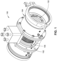
- FIGS. 1 through 4 illustrate a food cutter assembly 100 in accordance with embodiments of this disclosure.
- the features associated with the food cutter assembly 100 eliminate the risk of contaminating the assembly and reduces down time for the assembly.
- the food cutter assembly is shown to include a housing 104 for a spindle 102 having a cutting tool 132 coupled to an end of the spindle 102 for processing food product 128 supplied to the food cutter assembly 100 by a food product processing path (e.g., as shown in FIG. 4 ).
- a food product processing path e.g., as shown in FIG. 4
- the specification discusses potatoes as food product 128, other food products can be cut with cutting tool 132.
- food product 128 can include all types of potatoes, sweet potatoes yams, apples, pears, carrots and other types of fruits and vegetables with similar flesh density. In some situations, food product 128 and be a frozen and/or chilled food product to provide a proper hardness for cutting.
- the spindle 102 can be rotated by a sprocket 146 formed around the spindle 102 to be driven by a belt 148.
- FIG. 4 shows an embodiment of the food cutter assembly 100 implemented in a food product processing path with a motor 158 that drives the belt 148 to turn the sprocket 146.
- FIGS. 2 and 3 show cross-sectional isometric views of the food cutter assembly 100.
- the food cutter assembly 100 may include one or more radial bearings (e.g., a first radial bearing 134 and a second radial bearing 136) for rotationally mounting a spindle body 106 of the spindle 102.
- the spindle body 106 may be fixedly connected with one or more thrust discs (e.g. a first thrust disc 112 and a second thrust disc 120) that reduce or eliminate contact between the spindle body 106 and the housing 104.
- thrust discs e.g. a first thrust disc 112 and a second thrust disc 120
- the one or more thrust discs may be connected to the spindle body 106 by an interference fit, where the one or more discs are heated and the spindle is cooled while the components are fit together so that they tighten up as they return to their previous temperatures.
- the thrust discs may be formed of stainless steel.
- the first thrust disc 112 has first opposing surfaces 114 and 116 and a first circumferential surface 118
- the second thrust disc 120 has second opposing surfaces 122 and 124 and a second circumferential surface 126.
- the first thrust disc 112 can include first opposing surfaces 114 and 116 that extend radially from a rotational axis 110 of the spindle body 106, and the first circumferential surface 118 can be located between the first opposing surfaces 114 and 116.
- the second thrust disc 120 (and possibly other thrust discs) can be similarly structured.
- the first radial bearing 134 can be positioned proximate to the first thrust disc 112, and the second radial bearing 136 can be positioned proximate to the second thrust disc 120 when the spindle body 106 is rotationally mounted to the housing 104.
- the first radial bearing 134 and the second radial bearing 136 are formed of a food grade plastic (e.g., Nylon 6, high density polyethylene, polyethylen terephthyalate, or the like).
- the spindle body 106 and the housing 104 can define one or more fluid passages in between components of the food cutter assembly 100 that move relative to one another.
- the spindle body 106 and the housing 104 can define first fluid passages 138 extending from a first port 140 in the housing through the first radial bearing 134 to the spindle body 106 and across the first opposing surfaces 114 and 116 and the first circumferential surface 118 to the spindle body 106.
- the spindle body 106 and the housing 104 can also define second fluid passages 142 extending from a second port 144 in the housing 104 through the second radial bearing 136 to the spindle body 106 and across the second opposing surfaces 122 and 124 and the second circumferential surface 126 to the spindle body 106.
- first and second bearings and first and second thrust discs are shown in FIGS. 2 and 3 , in other embodiments, the food cutter assembly 100 may include a single bearing or thrust disc, or more than two bearings or thrust discs. In the illustrated embodiment, first and second bearings and thrust discs are arranged on either side of the sprocket 146. This configuration may provide improved balance and allow the spindle 102 smoothly when the sprocket is driven by the belt 148.
- a cutting tool 132 is connected to an end of the spindle body 106 for processing (e.g., cutting or slicing) food product 128 received at the food cutter assembly 100.
- the cutting tool 132 can include a plurality a helical knife having one or more helical or spiral shaped blades for shaping food product 128 into cut food product segments 130 (e.g. spiral cut shapes and other shapes).
- the cutting tool 132 may include a pulverizer or any other rotationally driven food processing element.
- the spindle body 106 may be rotated by the sprocket 146 that is fixedly connected to the spindle body 106 and driven by the belt 148 (e.g., as shown in FIG. 4 ), whereby the spindle's movement causes the cutting tool 132 to rotate about a rotational axis 110 that is aligned with a processing path of the food product 128.
- the spindle body 106 can also define an interior passage 108 extending along the rotational axis 110. The interior passage 108 can receive the cut food product segments 130 from the cutting tool 132.
- a tube 154 is located in the interior passage along the length of the spindle body 106 for receiving the cut food product segments 130 and transporting the cut food product segments 130 to another portion of the food product processing path.
- the tube 154 can transport the cut food product segments 130 to another food processing device or station, or to a storage container.
- the spindle body 106 can rotate around the tube 154, which can be stationary relative to the food product processing path.
- the tub 154 may be configured to fixedly connect to the housing 104 and extend into the spindle body 106 to receive the cut food product segments 130 from the cutting tool 132.
- the tube 154 may also serve to protect the cut food product segments 130 from being damaged or broken down further by the rotating spindle body 106.
- the spindle body 106 and/or the tube 154 can be formed of a food grade plastic material.
- Water (or another food safe fluid) can be pumped through the fluid passages 138 and 142 to create a water film between the housing 104 and the spindle body 106, where the water film serves to reduce friction between the housing 104 and the spindle body 106 while the spindle 102 is being rotated.
- arrows in FIG. 3 illustrate the water flow through fluid passages 138 and 142.
- fresh water can be supplied for the fluid passages 138 and 142 from a water source (e.g., a city water tap).
- Water for the fluid passages 138 and 142 may be suppled from the water source at a water pressure in the range of approximately 276 kPa to 552 kPa (40 psi to 80 psi) for example the water may be supplied at approximately 414 kPa (60 psi). In some cases, keeping the water pressure above approximately 276 kPa (40 psi) may avoid bacteria or mold build up.
- Using water as a lubricant for the food cutter assembly 100 can reduce the risk of contaminating or otherwise negatively impacting the food product 128 during its processing.
- food safe oils can be used to lubricate processing components; however, these can seep into the food product processing stream and end up the processed food product 128 (e.g., in the cut food product segments 130).
- the food cutter assembly 100 described herein can be lubricated with water that is pumped through the fluid passages 138 and 142, thus the seepage of lubricant (i.e., the water) into the food product processing stream has no negative impact on the food product 128, which is already being driven through the food product processing path by water.
- the food cutter assembly 100 can include respective seals (e.g., a first seal 150 and a second seal 152) for each of the first and second radial bearings 134 and 136 to keep the water from leaking out of the first and second radial bearings 134 and 136, and to maintain the water at a pressure sufficient to create a film that lubricates the spindle body 106 and thrust discs 112 and 120 as they rotate relative to the housing 104.
- the first seal 150 is adjacent to the first thrust disc 112 and the second seal 152 is adjacent to the second thrust disc 120 with the sprocket 146 disposed between the first seal 150 and the second seal 152.
- the first and second seals 150 and 152 may have seal ports (not shown) that allow the water to exit in a controlled fashion from the fluid passages 138 and 142 so that fresh water can be continuously supplied.
- the water can serve a variety of purposes. For example, in addition to reducing friction between the spindle body 106 and the housing 104, the water pumped through the fluid passages can cool the food cutter assembly 100 and prevent accumulation of debris (e.g., starch) from the food product 128 in spaces between the spindle body 106 and the tube 154.
- the spindle body 106 and the tube 154 define an opening at a first end (e.g., opposite the cutting tool 132) that allows water to enter between the spindle body 106 and the tube 154, thereby creating a film between the spindle body 106 and the tube 154 to reduce friction between the two components.
- the separation (or play) between the spindle body 106 and the tube 154 can be in the range of 0,127 mm to 0,762 mm (.005 to .030 inches), for example the spindle body 106 and the tube 154 can have a separation tolerance of approximately 0,254 mm to 0,381 mm (.010 to .015 in.).
- the separation (or play) at the opening at the first end, where water can enter the space between the spindle body 106 and the tube 154 may be in the range of 0,254 mm to 0,762 mm (.010 to .030 in.), for example the play between ends of the spindle body 106 and the tube 154 that form the opening may approximately 0,381 mm (.015 in.).
- the spindle body 106 and the tube 154 can also have an opening at a second end (e.g., proximate to the cutting tool 132) that allows water to exit from between the spindle body 106 and the tube 154 and enter the tube 154.
- the water can serve to reduce friction between the spindle body 106 and the tube 154, and the water can also serve to clean out the space between the spindle body 106 and the tube 154 and/or the inner surface of the tube 154.
- FIG. 4 shows an embodiment of the food cutter assembly 100 implemented in a food product processing path with a motor 158 that drives the belt 148 to turn the sprocket 146.
- the motion of the belt 148 causes the spindle 102 to rotate and spin the cutting tool 132 at the end of the spindle 102.
- the motor 158 is a 7,46 kW (10 hp), 3600 revolution per minute (rpm) motor; however, any motor with sufficient horsepower and torque can be utilized. The requisite horsepower and torque may depend on the food product 128, cutting tool 132, and so forth.
- the sprocket 146, belt 148, and motor 158 are configured to rotate the spindle 102 at a rate in the range of approximately 3000 to 6000 rpm, for example, the spindle 102 may be driven to rotate at a rate of approximately 4500 rpm.
- the food product 128 can be fed into the food cutter assembly 100 (e.g., through the cutting tool 132) via one or more supply tubes, where the food product is transported through the tubes by flowing water.
- the water flow rate through the one or more supply tubes is in the range of approximately 1514 to 2650 litres (400 to 700 gallons) per minute, or any flow rate sufficient for driving the food product 128 through the one or more supply tubes at a sufficient speed for the food cutter assembly 100 to process the food product 128.
- the one or more supply tubes can include a perforated tube 156 that directs the food product 128 into the food cutter assembly 100.
- the perforated tube 156 may include a tapered portion that aligns the food product 128 with the cutting tool 132 of the food cutter assembly 100.
- a portion of the water used to transport the food product 128 may be shed through openings in the perforated tube 156 through a bypass tube 160 and drained out of the system, while some of the water may enter the interior passage of the spindle body 106 (e.g., into tube 154) through the cutting tool 132.
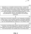
- FIG. 5 is a flow chart illustrating a method 200 for supplying a food safe fluid, such as water, to lubricate one or more radial bearings of a food cutter assembly, such as the food cutter assembly 100 described herein.
- the method 200 can include the following blocks.
- the method 200 can also include one or more operations or blocks relating to aspects or features of the food cutter assembly 100 described herein.
- the method 200 can include receiving a supply of water at the housing 104 for rotationally mounting the spindle body 106 having rotational axis 110, where the housing 104 includes one or more radial bearings (e.g., first radial bearing 134 and/or second radial bearing 136) proximate to one or more thrust discs (e.g., first thrust disc 112 and/or second thrust disc 120) of the spindle body 106.
- radial bearings e.g., first radial bearing 134 and/or second radial bearing 1366
- thrust discs e.g., first thrust disc 112 and/or second thrust disc 120
- the water can be directed through fluid passages (e.g., first fluid passages 138 and/or second fluid passages 142) extending from one or more respective ports (e.g., first port 140 and/or second port 144) in the housing 104 through the one or more radial bearings to the spindle body 106 and across the opposing surfaces (e.g., first opposing surfaces 114 and 116 and/or second opposing surfaces 122 and 124) and the circumferential surface (e.g., first circumferential surface 118 and/or second circumferential surface 126) of each of the one or more radial bearings to the spindle body 106.
- fluid passages e.g., first fluid passages 138 and/or second fluid passages 142
- first port 140 and/or second port 144 extending from one or more respective ports (e.g., first port 140 and/or second port 144) in the housing 104 through the one or more radial bearings to the spindle body 106 and across the opposing surfaces (e.
- the spindle body 106 may be rotated while the water is directed through the fluid passages to create a water film between the housing 104 and the spindle body 106 that reduces friction between the housing 104 and the spindle body 106.
- the water directed through the fluid passages may also cool the housing 104 and the spindle body 106 and/or other portions of the food cutter assembly 100.
Landscapes
- Engineering & Computer Science (AREA)
- Mechanical Engineering (AREA)
- Life Sciences & Earth Sciences (AREA)
- Forests & Forestry (AREA)
- General Engineering & Computer Science (AREA)
- Food-Manufacturing Devices (AREA)
- Nonmetal Cutting Devices (AREA)
- Preparation Of Fruits And Vegetables (AREA)
Claims (16)
- Ensemble de coupe-aliments (100) comprenant:un corps de broche (106) définissant un passage inférieur (108) destiné à recevoir un produit alimentaire, le passage intérieur s'étendant le long d'un axe de rotation (110) du corps de broche;un premier disque de poussée (112) connecté fixement au corps de broche, le premier disque de poussée incluant des premières surfaces opposées (114, 116) s'étendant de manière radiale depuis l'axe de rotation du corps de broche et une première surface circonférentielle (118) entre les premières surfaces opposées;un outil coupant (132) connecté à une extrémité du corps de broche destiné à couper le produit alimentaire, le passage intérieur configuré pour recevoir le produit alimentaire; etun boîtier (104) destiné au montage en rotation du corps de broche, le boîtier incluant un premier roulement radial (134) devant être positionné à proximité du premier disque de poussée quand le corps de broche est monté en rotation sur le boîtier, dans lequel le corps de broche et le boîtier définissent des premiers passages de fluide (138) s'étendant depuis un premier orifice (140) dans le boîtier à travers le premier palier radial jusqu'au corps de broche,caractérisé en ce queles premiers passages de fluide s'étendent en travers des premières surfaces opposées et de la première surface circonférentielle jusqu'au corps de broche.
- Ensemble de coupe d'aliments selon la revendication 1 comprenant en outre:un deuxième disque de poussée (120) connecté fixement au corps de broche, le deuxième disque de poussée incluant des deuxièmes surfaces opposées (122, 124) s'étendant de manière radiale depuis l'axe de rotation du corps de broche et une deuxième surface circonférentielle (126) entre les deuxièmes surfaces opposées;le boîtier incluant un deuxième roulement radial (136) devant être positionné à proximité du deuxième disque de poussée quand le corps de broche est monté en rotation sur le boîtier, dans lequel le corps de broche et le boîtier définissent des deuxièmes passages de fluide (142) s'étendant depuis un deuxième orifice (144) dans le boîtier à travers le deuxième palier radial jusqu'au corps de broche et en travers des deuxièmes surfaces opposées et de la deuxième surface circonférentielle jusqu'au corps de broche.
- Ensemble de coupe d'aliments tel que décrit dans la revendication 1 ou 2, comprenant en outre un pignon (146) connecté fixement au corps de broche et configuré pour être entraîné par une courroie (148) pour faire tourner le corps de broche.
- Ensemble de coupe d'aliments tel que décrit dans la revendication 1 ou 2, dans lequel le boîtier comprend un premier joint étanche (150) adjacent au premier disque de poussée et si un deuxième disque de poussée est présent, un deuxième joint étanche (152) adjacent au deuxième disque de poussée, le pignon disposé entre le premier joint étanche et le deuxième joint étanche.
- Ensemble de coupe d'aliments tel que décrit dans la revendication 1 ou 2, dans lequel le premier disque de poussée et/ou le deuxième disque de poussée s'il est présent se connectent au corps de broche par un ajustement avec serrage.
- Ensemble de coupe d'aliments tel que décrit dans la revendication 1 ou 2, comprenant en outre un tube (154) configuré pour se connecter fixement au boîtier et s'étendre jusque dans le corps de broche pour recevoir le produit alimentaire coupé de l'outil coupant.
- Ensemble de coupe d'aliments tel que décrit dans la revendication 1 ou 2, dans lequel l'outil coupant comprend un couteau hélicoïdal.
- Ensemble de coupe d'aliments tel que décrit dans la revendication 1 ou 2, comprenant en outre un tube perforé (156) configuré pour fournir le produit alimentaire à l'outil coupant avec une alimentation en eau.
- Procédé comprenant:la réception, au niveau d'un boîtier (104) destiné au montage en rotation d'un corps de broche (106) ayant un axe de rotation (110), d'une alimentation en eau, le boîtier incluant un premier roulement radial (134) à proximité d'un premier disque de poussée (112) du corps de broche, le premier disque de poussée incluant des premières surfaces opposées (114, 116) s'étendant de manière radiale depuis l'axe de rotation du corps de broche et une première surface circonférentielle (118) entre les premières surfaces opposées;la direction de l'eau à travers des premiers passages de fluide (138) s'étendant depuis un premier orifice (140) dans le boîtier à travers le premier palier radial jusqu'au corps de broche et en travers des premières surfaces opposées et de la première surface circonférentielle jusqu'au corps de broche; etla rotation du corps de broche pendant que l'eau est dirigée à travers les premier passages de fluide pour créer un film d'eau entre le boîtier et le corps de broche qui réduit le frottement entre le boîtier et le corps de broche.
- Procédé tel que décrit dans la revendication 9 comprenant en outre:la réception, au niveau d'un boîtier destiné au montage en rotation d'un corps de broche ayant un axe de rotation, d'une alimentation en eau, le boîtier incluant un deuxième roulement radial (136) à proximité d'un deuxième disque de poussée (120) du corps de broche, le deuxième disque de poussée incluant des deuxièmes surfaces opposées (122, 124) s'étendant de manière radiale depuis l'axe de rotation du corps de broche et une deuxième surface circonférentielle (126) entre les deuxièmes surfaces opposées;la direction de l'eau à travers des deuxièmes passages de fluide (142) s'étendant depuis un deuxième orifice (144) dans le boîtier à travers le deuxième palier radial jusqu'au corps de broche et en travers des deuxièmes surfaces opposées et de la deuxième surface circonférentielle jusqu'au corps de broche; etla rotation du corps de broche pendant que l'eau est dirigée à travers les deuxièmes passages de fluide pour créer un film d'eau entre le boîtier et le corps de broche qui réduit le frottement entre le boîtier et le corps de broche.
- Procédé tel que décrit dans la revendication 9 ou 10, comprenant en outre le refroidissement du boîtier et du corps de broche avec l'eau.
- Procédé tel que décrit dans la revendication 9 ou 10 dans lequel le corps de broche définit un passage intérieur (108) destiné à recevoir un produit alimentaire, le passage intérieur s'étendant le long de l'axe de rotation du corps de broche.
- Procédé tel que décrit dans la revendication 9 ou 10, dans lequel le corps de broche est formé d'une matière plastique de qualité alimentaire.
- Procédé tel que décrit dans la revendication 9 ou 10, dans lequel le premier disque de poussée et/ou le deuxième disque de poussée s'il est présent sont connectés fixement au corps de broche.
- Procédé tel que décrit dans la revendication 9 ou 10, dans lequel un outil coupant est connecté à une extrémité du corps de broche destiné à couper le produit alimentaire, et le passage intérieur est configuré pour recevoir le produit alimentaire.
- Procédé tel que décrit dans la revendication 9 ou 10, dans lequel le corps de broche comprend un pignon (146), et la rotation du corps de broche comprend l'entraînement du pignon avec une courroie (148).
Applications Claiming Priority (3)
| Application Number | Priority Date | Filing Date | Title |
|---|---|---|---|
| US15/426,492 US10384364B2 (en) | 2017-02-07 | 2017-02-07 | Water bearing and food cutting assembly |
| US15/426,520 US10363679B2 (en) | 2017-02-07 | 2017-02-07 | Water bearing and food cutting assembly |
| PCT/US2018/016572 WO2018148112A1 (fr) | 2017-02-07 | 2018-02-02 | Ensemble à circulation d'eau et coupe d'aliments |
Publications (3)
| Publication Number | Publication Date |
|---|---|
| EP3580028A1 EP3580028A1 (fr) | 2019-12-18 |
| EP3580028A4 EP3580028A4 (fr) | 2020-11-11 |
| EP3580028B1 true EP3580028B1 (fr) | 2024-07-24 |
Family
ID=63107857
Family Applications (1)
| Application Number | Title | Priority Date | Filing Date |
|---|---|---|---|
| EP18751551.5A Active EP3580028B1 (fr) | 2017-02-07 | 2018-02-02 | Ensemble à circulation d'eau et coupe d'aliments |
Country Status (5)
| Country | Link |
|---|---|
| EP (1) | EP3580028B1 (fr) |
| CN (1) | CN110267781B (fr) |
| AU (1) | AU2018219148B2 (fr) |
| CA (1) | CA3051464A1 (fr) |
| WO (1) | WO2018148112A1 (fr) |
Families Citing this family (3)
| Publication number | Priority date | Publication date | Assignee | Title |
|---|---|---|---|---|
| US20180132850A1 (en) * | 2014-03-26 | 2018-05-17 | Ethicon Llc | Surgical instrument comprising a sensor system |
| US12064890B2 (en) | 2020-02-12 | 2024-08-20 | Lamb Weston, Inc. | Water bearing and food cutting assembly with magnetically rotated cutting head |
| CA3275745A1 (en) * | 2024-05-31 | 2026-01-19 | Vanmark Equipment, Llc | Helical Cutter |
Citations (1)
| Publication number | Priority date | Publication date | Assignee | Title |
|---|---|---|---|---|
| US5394793A (en) * | 1993-06-02 | 1995-03-07 | Lamb-Weston, Inc. | Food processing system with rotating knife |
Family Cites Families (10)
| Publication number | Priority date | Publication date | Assignee | Title |
|---|---|---|---|---|
| US4082024A (en) * | 1976-11-29 | 1978-04-04 | Ore-Ida Foods, Inc. | Potato strip cutter |
| US4644838A (en) * | 1983-09-20 | 1987-02-24 | Rogers Walla-Walla, Inc. | Apparatus for helical cutting of potatoes |
| US4884899A (en) * | 1987-04-03 | 1989-12-05 | Schwartzman Everett H | Resiliently mounted fluid bearing assembly |
| US5179881A (en) * | 1991-04-23 | 1993-01-19 | Mccain Foods Limited | System for producing helical vegetable strips and turbine therefor |
| US5168784A (en) * | 1991-09-19 | 1992-12-08 | Universal Frozen Foods, Inc. | Hydro-cutter |
| US7137325B2 (en) * | 2003-11-05 | 2006-11-21 | Frito-Lay North America, Inc. | System for conveying and slicing |
| MX339388B (es) * | 2011-03-14 | 2016-05-24 | Kellog Co | Aparato para producto alimenticio extruido y enroscado. |
| CN102630899B (zh) * | 2012-05-09 | 2013-05-08 | 四川省农业科学院农产品加工研究所 | 薯类全营养粉的加工方法 |
| CA2876575A1 (fr) * | 2012-07-05 | 2014-01-09 | Minesto Ab | Dispositif pour coussinet autolubrifiant |
| US9970451B2 (en) * | 2013-05-30 | 2018-05-15 | Ingersoll-Rand Company | Centrifugal compressor having lubricant distribution system |
-
2018
- 2018-02-02 AU AU2018219148A patent/AU2018219148B2/en active Active
- 2018-02-02 EP EP18751551.5A patent/EP3580028B1/fr active Active
- 2018-02-02 CN CN201880010716.6A patent/CN110267781B/zh active Active
- 2018-02-02 CA CA3051464A patent/CA3051464A1/fr active Pending
- 2018-02-02 WO PCT/US2018/016572 patent/WO2018148112A1/fr not_active Ceased
Patent Citations (1)
| Publication number | Priority date | Publication date | Assignee | Title |
|---|---|---|---|---|
| US5394793A (en) * | 1993-06-02 | 1995-03-07 | Lamb-Weston, Inc. | Food processing system with rotating knife |
Also Published As
| Publication number | Publication date |
|---|---|
| NZ755576A (en) | 2025-08-29 |
| AU2018219148A1 (en) | 2019-08-01 |
| CN110267781A (zh) | 2019-09-20 |
| EP3580028A4 (fr) | 2020-11-11 |
| CN110267781B (zh) | 2022-06-03 |
| EP3580028A1 (fr) | 2019-12-18 |
| AU2018219148B2 (en) | 2024-12-12 |
| CA3051464A1 (fr) | 2018-08-16 |
| WO2018148112A8 (fr) | 2019-02-14 |
| WO2018148112A1 (fr) | 2018-08-16 |
Similar Documents
| Publication | Publication Date | Title |
|---|---|---|
| US10384364B2 (en) | Water bearing and food cutting assembly | |
| AU2018219148B2 (en) | Water bearing and food cutting assembly | |
| US10363679B2 (en) | Water bearing and food cutting assembly | |
| US6460444B2 (en) | Rotary apparatus for cutting a food product | |
| AU655251B2 (en) | System for producing helical vegetable strips | |
| MXPA05001749A (es) | Metodo y aparato para congelacion superficiel externa de productos alimenticios. | |
| US4462221A (en) | Apparatus for cooling bulk products | |
| US12064890B2 (en) | Water bearing and food cutting assembly with magnetically rotated cutting head | |
| US2712734A (en) | Ice making machine | |
| US4949612A (en) | Apparatus for slicing vegetables | |
| US5528967A (en) | Fluid jet fruit slicer | |
| US20070199421A1 (en) | Cutting head of an eccentric cutting machine | |
| CN206596639U (zh) | 一种魔芋切片分拣流水线设备 | |
| NZ755576B2 (en) | Water bearing and food cutting assembly | |
| EP4656338A2 (fr) | Dispositif de coupe hélicoïdal et joint à labyrinthe | |
| US5448894A (en) | Disk flake ice machine | |
| US9821485B2 (en) | Rotating cutting blade assembly | |
| CA3146021A1 (fr) | Dispositif de coupe hydromecanique | |
| US20240260594A1 (en) | Contact drum freezer system for automated and/or mech-anized food process lines, and products produced thereby | |
| AU740132B2 (en) | Ice slurry machine | |
| US11207793B2 (en) | Hydro-mechanical cutter | |
| CN109397367A (zh) | 新鲜肉类切丁机 | |
| CN114080308A (zh) | 液压机械切割器 | |
| RU2025106942A (ru) | Устройство для отделения мяса от туши или ее частей, а также устройство и способ автоматизированной обработки продуктов пищевой промышленности |
Legal Events
| Date | Code | Title | Description |
|---|---|---|---|
| STAA | Information on the status of an ep patent application or granted ep patent |
Free format text: STATUS: THE INTERNATIONAL PUBLICATION HAS BEEN MADE |
|
| PUAI | Public reference made under article 153(3) epc to a published international application that has entered the european phase |
Free format text: ORIGINAL CODE: 0009012 |
|
| STAA | Information on the status of an ep patent application or granted ep patent |
Free format text: STATUS: REQUEST FOR EXAMINATION WAS MADE |
|
| 17P | Request for examination filed |
Effective date: 20190807 |
|
| AK | Designated contracting states |
Kind code of ref document: A1 Designated state(s): AL AT BE BG CH CY CZ DE DK EE ES FI FR GB GR HR HU IE IS IT LI LT LU LV MC MK MT NL NO PL PT RO RS SE SI SK SM TR |
|
| AX | Request for extension of the european patent |
Extension state: BA ME |
|
| DAV | Request for validation of the european patent (deleted) | ||
| DAX | Request for extension of the european patent (deleted) | ||
| A4 | Supplementary search report drawn up and despatched |
Effective date: 20201009 |
|
| RIC1 | Information provided on ipc code assigned before grant |
Ipc: F16C 17/10 20060101ALI20201005BHEP Ipc: F16C 17/14 20060101ALI20201005BHEP Ipc: B26D 1/00 20060101ALI20201005BHEP Ipc: B26D 3/11 20060101ALI20201005BHEP Ipc: F16C 33/10 20060101ALI20201005BHEP Ipc: B26D 3/26 20060101AFI20201005BHEP Ipc: B26D 7/00 20060101ALI20201005BHEP Ipc: B26D 1/36 20060101ALI20201005BHEP Ipc: B26D 1/28 20060101ALI20201005BHEP Ipc: B26D 7/06 20060101ALI20201005BHEP Ipc: B26D 1/03 20060101ALI20201005BHEP |
|
| P01 | Opt-out of the competence of the unified patent court (upc) registered |
Effective date: 20230521 |
|
| GRAP | Despatch of communication of intention to grant a patent |
Free format text: ORIGINAL CODE: EPIDOSNIGR1 |
|
| STAA | Information on the status of an ep patent application or granted ep patent |
Free format text: STATUS: GRANT OF PATENT IS INTENDED |
|
| RIC1 | Information provided on ipc code assigned before grant |
Ipc: B26D 1/00 20060101ALI20240131BHEP Ipc: B26D 7/00 20060101ALI20240131BHEP Ipc: B26D 1/03 20060101ALI20240131BHEP Ipc: B26D 1/36 20060101ALI20240131BHEP Ipc: B26D 1/28 20060101ALI20240131BHEP Ipc: F16C 17/14 20060101ALI20240131BHEP Ipc: F16C 33/20 20060101ALI20240131BHEP Ipc: F16C 33/10 20060101ALI20240131BHEP Ipc: F16C 17/10 20060101ALI20240131BHEP Ipc: F16C 17/02 20060101ALI20240131BHEP Ipc: B26D 3/11 20060101ALI20240131BHEP Ipc: B26D 7/06 20060101ALI20240131BHEP Ipc: B26D 3/26 20060101AFI20240131BHEP |
|
| INTG | Intention to grant announced |
Effective date: 20240213 |
|
| GRAS | Grant fee paid |
Free format text: ORIGINAL CODE: EPIDOSNIGR3 |
|
| GRAA | (expected) grant |
Free format text: ORIGINAL CODE: 0009210 |
|
| STAA | Information on the status of an ep patent application or granted ep patent |
Free format text: STATUS: THE PATENT HAS BEEN GRANTED |
|
| AK | Designated contracting states |
Kind code of ref document: B1 Designated state(s): AL AT BE BG CH CY CZ DE DK EE ES FI FR GB GR HR HU IE IS IT LI LT LU LV MC MK MT NL NO PL PT RO RS SE SI SK SM TR |
|
| REG | Reference to a national code |
Ref country code: GB Ref legal event code: FG4D |
|
| REG | Reference to a national code |
Ref country code: CH Ref legal event code: EP |
|
| REG | Reference to a national code |
Ref country code: IE Ref legal event code: FG4D Ref country code: DE Ref legal event code: R096 Ref document number: 602018072183 Country of ref document: DE |
|
| REG | Reference to a national code |
Ref country code: NL Ref legal event code: FP |
|
| REG | Reference to a national code |
Ref country code: LT Ref legal event code: MG9D |
|
| PG25 | Lapsed in a contracting state [announced via postgrant information from national office to epo] |
Ref country code: PT Free format text: LAPSE BECAUSE OF FAILURE TO SUBMIT A TRANSLATION OF THE DESCRIPTION OR TO PAY THE FEE WITHIN THE PRESCRIBED TIME-LIMIT Effective date: 20241125 |
|
| REG | Reference to a national code |
Ref country code: AT Ref legal event code: MK05 Ref document number: 1705912 Country of ref document: AT Kind code of ref document: T Effective date: 20240724 |
|
| PG25 | Lapsed in a contracting state [announced via postgrant information from national office to epo] |
Ref country code: PT Free format text: LAPSE BECAUSE OF FAILURE TO SUBMIT A TRANSLATION OF THE DESCRIPTION OR TO PAY THE FEE WITHIN THE PRESCRIBED TIME-LIMIT Effective date: 20241125 |
|
| PG25 | Lapsed in a contracting state [announced via postgrant information from national office to epo] |
Ref country code: NO Free format text: LAPSE BECAUSE OF FAILURE TO SUBMIT A TRANSLATION OF THE DESCRIPTION OR TO PAY THE FEE WITHIN THE PRESCRIBED TIME-LIMIT Effective date: 20241024 |
|
| PG25 | Lapsed in a contracting state [announced via postgrant information from national office to epo] |
Ref country code: FI Free format text: LAPSE BECAUSE OF FAILURE TO SUBMIT A TRANSLATION OF THE DESCRIPTION OR TO PAY THE FEE WITHIN THE PRESCRIBED TIME-LIMIT Effective date: 20240724 Ref country code: PL Free format text: LAPSE BECAUSE OF FAILURE TO SUBMIT A TRANSLATION OF THE DESCRIPTION OR TO PAY THE FEE WITHIN THE PRESCRIBED TIME-LIMIT Effective date: 20240724 Ref country code: GR Free format text: LAPSE BECAUSE OF FAILURE TO SUBMIT A TRANSLATION OF THE DESCRIPTION OR TO PAY THE FEE WITHIN THE PRESCRIBED TIME-LIMIT Effective date: 20241025 |
|
| PG25 | Lapsed in a contracting state [announced via postgrant information from national office to epo] |
Ref country code: BG Free format text: LAPSE BECAUSE OF FAILURE TO SUBMIT A TRANSLATION OF THE DESCRIPTION OR TO PAY THE FEE WITHIN THE PRESCRIBED TIME-LIMIT Effective date: 20240724 |
|
| PG25 | Lapsed in a contracting state [announced via postgrant information from national office to epo] |
Ref country code: LV Free format text: LAPSE BECAUSE OF FAILURE TO SUBMIT A TRANSLATION OF THE DESCRIPTION OR TO PAY THE FEE WITHIN THE PRESCRIBED TIME-LIMIT Effective date: 20240724 |
|
| PG25 | Lapsed in a contracting state [announced via postgrant information from national office to epo] |
Ref country code: IS Free format text: LAPSE BECAUSE OF FAILURE TO SUBMIT A TRANSLATION OF THE DESCRIPTION OR TO PAY THE FEE WITHIN THE PRESCRIBED TIME-LIMIT Effective date: 20241124 Ref country code: AT Free format text: LAPSE BECAUSE OF FAILURE TO SUBMIT A TRANSLATION OF THE DESCRIPTION OR TO PAY THE FEE WITHIN THE PRESCRIBED TIME-LIMIT Effective date: 20240724 |
|
| PG25 | Lapsed in a contracting state [announced via postgrant information from national office to epo] |
Ref country code: HR Free format text: LAPSE BECAUSE OF FAILURE TO SUBMIT A TRANSLATION OF THE DESCRIPTION OR TO PAY THE FEE WITHIN THE PRESCRIBED TIME-LIMIT Effective date: 20240724 |
|
| PG25 | Lapsed in a contracting state [announced via postgrant information from national office to epo] |
Ref country code: RS Free format text: LAPSE BECAUSE OF FAILURE TO SUBMIT A TRANSLATION OF THE DESCRIPTION OR TO PAY THE FEE WITHIN THE PRESCRIBED TIME-LIMIT Effective date: 20241024 Ref country code: ES Free format text: LAPSE BECAUSE OF FAILURE TO SUBMIT A TRANSLATION OF THE DESCRIPTION OR TO PAY THE FEE WITHIN THE PRESCRIBED TIME-LIMIT Effective date: 20240724 |
|
| PG25 | Lapsed in a contracting state [announced via postgrant information from national office to epo] |
Ref country code: RS Free format text: LAPSE BECAUSE OF FAILURE TO SUBMIT A TRANSLATION OF THE DESCRIPTION OR TO PAY THE FEE WITHIN THE PRESCRIBED TIME-LIMIT Effective date: 20241024 Ref country code: PL Free format text: LAPSE BECAUSE OF FAILURE TO SUBMIT A TRANSLATION OF THE DESCRIPTION OR TO PAY THE FEE WITHIN THE PRESCRIBED TIME-LIMIT Effective date: 20240724 Ref country code: NO Free format text: LAPSE BECAUSE OF FAILURE TO SUBMIT A TRANSLATION OF THE DESCRIPTION OR TO PAY THE FEE WITHIN THE PRESCRIBED TIME-LIMIT Effective date: 20241024 Ref country code: LV Free format text: LAPSE BECAUSE OF FAILURE TO SUBMIT A TRANSLATION OF THE DESCRIPTION OR TO PAY THE FEE WITHIN THE PRESCRIBED TIME-LIMIT Effective date: 20240724 Ref country code: IS Free format text: LAPSE BECAUSE OF FAILURE TO SUBMIT A TRANSLATION OF THE DESCRIPTION OR TO PAY THE FEE WITHIN THE PRESCRIBED TIME-LIMIT Effective date: 20241124 Ref country code: HR Free format text: LAPSE BECAUSE OF FAILURE TO SUBMIT A TRANSLATION OF THE DESCRIPTION OR TO PAY THE FEE WITHIN THE PRESCRIBED TIME-LIMIT Effective date: 20240724 Ref country code: GR Free format text: LAPSE BECAUSE OF FAILURE TO SUBMIT A TRANSLATION OF THE DESCRIPTION OR TO PAY THE FEE WITHIN THE PRESCRIBED TIME-LIMIT Effective date: 20241025 Ref country code: FI Free format text: LAPSE BECAUSE OF FAILURE TO SUBMIT A TRANSLATION OF THE DESCRIPTION OR TO PAY THE FEE WITHIN THE PRESCRIBED TIME-LIMIT Effective date: 20240724 Ref country code: ES Free format text: LAPSE BECAUSE OF FAILURE TO SUBMIT A TRANSLATION OF THE DESCRIPTION OR TO PAY THE FEE WITHIN THE PRESCRIBED TIME-LIMIT Effective date: 20240724 Ref country code: BG Free format text: LAPSE BECAUSE OF FAILURE TO SUBMIT A TRANSLATION OF THE DESCRIPTION OR TO PAY THE FEE WITHIN THE PRESCRIBED TIME-LIMIT Effective date: 20240724 Ref country code: AT Free format text: LAPSE BECAUSE OF FAILURE TO SUBMIT A TRANSLATION OF THE DESCRIPTION OR TO PAY THE FEE WITHIN THE PRESCRIBED TIME-LIMIT Effective date: 20240724 |
|
| PG25 | Lapsed in a contracting state [announced via postgrant information from national office to epo] |
Ref country code: DK Free format text: LAPSE BECAUSE OF FAILURE TO SUBMIT A TRANSLATION OF THE DESCRIPTION OR TO PAY THE FEE WITHIN THE PRESCRIBED TIME-LIMIT Effective date: 20240724 Ref country code: RO Free format text: LAPSE BECAUSE OF FAILURE TO SUBMIT A TRANSLATION OF THE DESCRIPTION OR TO PAY THE FEE WITHIN THE PRESCRIBED TIME-LIMIT Effective date: 20240724 Ref country code: SM Free format text: LAPSE BECAUSE OF FAILURE TO SUBMIT A TRANSLATION OF THE DESCRIPTION OR TO PAY THE FEE WITHIN THE PRESCRIBED TIME-LIMIT Effective date: 20240724 |
|
| PG25 | Lapsed in a contracting state [announced via postgrant information from national office to epo] |
Ref country code: EE Free format text: LAPSE BECAUSE OF FAILURE TO SUBMIT A TRANSLATION OF THE DESCRIPTION OR TO PAY THE FEE WITHIN THE PRESCRIBED TIME-LIMIT Effective date: 20240724 |
|
| PG25 | Lapsed in a contracting state [announced via postgrant information from national office to epo] |
Ref country code: CZ Free format text: LAPSE BECAUSE OF FAILURE TO SUBMIT A TRANSLATION OF THE DESCRIPTION OR TO PAY THE FEE WITHIN THE PRESCRIBED TIME-LIMIT Effective date: 20240724 |
|
| REG | Reference to a national code |
Ref country code: DE Ref legal event code: R097 Ref document number: 602018072183 Country of ref document: DE |
|
| PG25 | Lapsed in a contracting state [announced via postgrant information from national office to epo] |
Ref country code: SK Free format text: LAPSE BECAUSE OF FAILURE TO SUBMIT A TRANSLATION OF THE DESCRIPTION OR TO PAY THE FEE WITHIN THE PRESCRIBED TIME-LIMIT Effective date: 20240724 Ref country code: IT Free format text: LAPSE BECAUSE OF FAILURE TO SUBMIT A TRANSLATION OF THE DESCRIPTION OR TO PAY THE FEE WITHIN THE PRESCRIBED TIME-LIMIT Effective date: 20240724 |
|
| PLBE | No opposition filed within time limit |
Free format text: ORIGINAL CODE: 0009261 |
|
| STAA | Information on the status of an ep patent application or granted ep patent |
Free format text: STATUS: NO OPPOSITION FILED WITHIN TIME LIMIT |
|
| 26N | No opposition filed |
Effective date: 20250425 |
|
| PG25 | Lapsed in a contracting state [announced via postgrant information from national office to epo] |
Ref country code: SE Free format text: LAPSE BECAUSE OF FAILURE TO SUBMIT A TRANSLATION OF THE DESCRIPTION OR TO PAY THE FEE WITHIN THE PRESCRIBED TIME-LIMIT Effective date: 20240724 |
|
| PG25 | Lapsed in a contracting state [announced via postgrant information from national office to epo] |
Ref country code: MC Free format text: LAPSE BECAUSE OF FAILURE TO SUBMIT A TRANSLATION OF THE DESCRIPTION OR TO PAY THE FEE WITHIN THE PRESCRIBED TIME-LIMIT Effective date: 20240724 |
|
| REG | Reference to a national code |
Ref country code: CH Ref legal event code: PL |
|
| PG25 | Lapsed in a contracting state [announced via postgrant information from national office to epo] |
Ref country code: LU Free format text: LAPSE BECAUSE OF NON-PAYMENT OF DUE FEES Effective date: 20250202 |
|
| PG25 | Lapsed in a contracting state [announced via postgrant information from national office to epo] |
Ref country code: CH Free format text: LAPSE BECAUSE OF NON-PAYMENT OF DUE FEES Effective date: 20250228 |
|
| PG25 | Lapsed in a contracting state [announced via postgrant information from national office to epo] |
Ref country code: FR Free format text: LAPSE BECAUSE OF NON-PAYMENT OF DUE FEES Effective date: 20250228 |
|
| PG25 | Lapsed in a contracting state [announced via postgrant information from national office to epo] |
Ref country code: IE Free format text: LAPSE BECAUSE OF NON-PAYMENT OF DUE FEES Effective date: 20250202 |
|
| PGFP | Annual fee paid to national office [announced via postgrant information from national office to epo] |
Ref country code: NL Payment date: 20260226 Year of fee payment: 9 |
|
| PGFP | Annual fee paid to national office [announced via postgrant information from national office to epo] |
Ref country code: GB Payment date: 20260227 Year of fee payment: 9 |
|
| PGFP | Annual fee paid to national office [announced via postgrant information from national office to epo] |
Ref country code: DE Payment date: 20260227 Year of fee payment: 9 |
|
| PGFP | Annual fee paid to national office [announced via postgrant information from national office to epo] |
Ref country code: BE Payment date: 20260227 Year of fee payment: 9 |